1
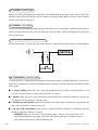
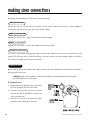
Model 200
Installation Guide
®
© 2001 Directed Electronics, Inc. Vista, CA N122 3-01
Rev. B 1.0
table of contents
What Is Included . . . . . . . . . . . . . . . . . . . . . 3
Plug-In LED and Valet/Program Switch . . . . . . 15
Installation Points to Remember . . . . . . . . . . 4
On-Board Doubleguard Shock Sensor . . . . . . . 15
Deciding on Component Locations
Siren . . . . . . . . . . . . . . . . . .
Control Module. . . . . . . . . . . .
Valet/Program Switch . . . . . . .
Status LED . . . . . . . . . . . . . .
.
.
.
.
.
.
.
.
.
.
.
.
.
.
.
.
.
.
.
.
.
.
.
.
.
.
.
.
.
.
.
.
.
.
.
.
.
.
.
.
.
.
.
.
.
5
5
5
5
5
Transmitter/Receiver Learn Routine. . . . . . . . 16
Finding the Wires You Need . .
Obtaining Constant 12V . . .
12V Switched Ignition Wire
Starter Wire. . . . . . . . . . .
(+) Parking Light Wire . . . .
.
.
.
.
.
.
.
.
.
.
.
.
.
.
.
.
.
.
.
.
.
.
.
.
.
.
.
.
.
.
.
.
.
.
.
.
.
.
.
.
.
.
.
.
.
6
6
6
7
7
.
.
.
.
.
.
.
.
.
.
.
.
.
.
.
System Features Learn Routine . . . . . . . . . . . 17
Features Menu . . . . . . . . . . . . . . . . . . . . . . 18
Feature Descriptions . . . . . . . . . . . . . . . . . . 18
Multi-Level Security Arming . . . . . . . . . . . . . 19
Nuisance Prevention Circuitry . . . . . . . . . . . . 20
Making Your Wiring Connections. . . . . . . . . . . 8
Diagnostics . . . . . . . . . . . . . . . . . . . . . . . . 20
Arming Diagnostics . . . . . . . . . . . . . . . . . 20
Disarming Diagnostics . . . . . . . . . . . . . . . 20
Primary Harness (H1), 14-Pin Connector . . . . . 9
Table of Zones . . . . . . . . . . . . . . . . . . . . . . 21
Primary Harness Wire Connection Guide. . . . . 10
Troubleshooting . . . . . . . . . . . . . . . . . . . . . 21
Making Siren Connections . . . . . . . . . . . . . . 14
Enabling the Back-Up Battery Siren . . . . . . 14
Wiring Quick Reference Guide . . . . . . . . . . . 24
Bitwriter™, Code Hopping™, DEI®, Doubleguard®, ESP™, FailSafe®, Ghost Switch™, Learn
Routine™, Nite-Lite®, Nuisance Prevention Circuitry®, NPC®, Revenger®, Silent Mode™, Soft Chirp®,
Stinger®, Valet®, Vehicle Recovery System®, VRS®, and Warn Away® are all Trademarks or Registered
Trademarks of Directed Electronics, Inc.
2
© 2001 Directed Electronics, Inc. Vista, CA
what is included
■
■
■
■
■
■
■
■
■
The control module (see diagram)
Two 470T Series remote transmitters
Primary harness
A plug-in status LED
A plug-in Valet® switch
An on-board shock sensor
A back-up battery siren
Two back-up battery siren keys
A mercury tilt switch (for motorcycle installations)
Shock Sensor
Sensitivity
Adjustment
Antenna
White
LED Port
(2-Pin Connector)
H1 Primary
Harness Port
(14-Pin Connector)
© 2001 Directed Electronics, Inc. Vista, CA
Blue Valet
Switch Port
(2-Pin Connector)
3
installation points to remember
This system has many unique features, some of which require unique testing procedures! Carefully review both
this installation guide and the owner’s guide before beginning the installation or this system, particularly the
wiring diagrams.
■ The control module’s PC board is protected with a conformal coating which will combat condensation buildup, however the system is NOT WATERPROOF. This system and all of its components MUST be installed in a
location where they cannot become wet or be submerged in water.
■ We recommend insulating all your soldered or crimped connections with heat shrink or electrical tape. We
also recommend spraying a silicone sealant on all your connections and plugs AFTER they are connected and
plugged in. Spraying beforehand prevents good electrical connections.
■ This unit is equipped with Nuisance Prevention Circuitry, which can bypass zones that are repeatedly triggered, causing them to appear not to work. For a detailed description of this feature, refer to the Nuisance
Prevention Circuitry section of the Owner's Guide.
■ If possible, consult with the customer to determine the location of the Status LED.
■ Never mount components where they can be easily disconnected, or where they might interfere with normal
operation or obstruct service technicians.
After the installation is complete:
■ Before mounting the control module, in conditions where moisture or condensation may build up around the
control module's Molex plugs, we recommend applying white lithium grease or an electrical conductive-type
grease around the control module’s Molex plug contacts to prevent the terminals from oxidizing.
■ Make sure to test all functions. The “Using Your System” section of the owner’s guide is very helpful when
testing the system.
4
© 2001 Directed Electronics, Inc. Vista, CA
deciding on component locations
locations for the siren
Some things to remember when mounting the siren:
■ Mount the siren with screws, taking care that the screws do not come in contact with any wire harnesses or
fluid lines.
■ Keep it away from heat sources. Radiators, exhaust manifolds, turbochargers, and heat shields are all locations to avoid.
■ Mount it where a thief cannot easily disconnect it. Both the siren and its wires should be difficult to find.
This usually involves disguising the wire to look like a factory harness.
■ Point the siren down so water does not collect in it.
■ When installing this system in watercraft, the siren must be mounted in a compartment that does not take
in water.
locations for the control module
Some things to remember when mounting the control module:
■ Mount the control module with the screws or with zip ties.
■ When locating the control module, keep it away from any heat sources or obvious leaks. Also keep the components and harnesses as far from the exhaust system as possible.
■ The higher the control module is mounted, the better the transmitter range will be.
■ When installing this system in watercraft, the control module must be mounted in a compartment that does
not take in water.
locations for the valet/program switch
The switch should be well hidden. It should be placed so passengers or stored items (such as near a luggage
carrier or saddlebags) cannot accidentally hit it. The switch fits in a 9/32-inch hole.
IMPORTANT! When the vehicle is delivered, please show the user where the switch is located and
how to disarm the system with it.
locations for the status LED
Things to remember when positioning the Status LED:
■ It should be visible from both sides and the rear of the vehicle, if possible.
■ It needs at least 1/2-inch clearance to the rear.
■ The LED fits in a 9/32-inch hole.
© 2001 Directed Electronics, Inc. Vista, CA
5
finding the wires you need
Now that you have decided where each component will be located, you’re going to find the wires in the vehicle
that the security system will be connected to.
IMPORTANT! Do not use a 12V test light to find these wires! Use a digital multimeter for all testing.
obtaining constant 12V
We recommend two possible sources for 12V constant: the (+) terminal of the battery, or the constant supply to
the ignition switch. Always install a fuse within 12 inches of this connection. If the fuse also will be powering
other circuits, fuse accordingly.
IMPORTANT! Do not remove the fuse holder on the red wire. It ensures that the control module has
its own fuse, of the proper value, regardless of how many accessories are added to the main power
feed.
finding the 12V switched ignition wire
The ignition wire is powered when the key is in the run and start positions. This is because the ignition wire
powers the ignition system (spark plugs, coil) as well as the fuel delivery system (fuel pump, fuel injection computer). Accessory wires lose power when the key is in the start position to make more current available to the starter
motor.
How to find (+)12V ignition with your multimeter:
1. Set to DCV or DC voltage (12V or 20V is fine).
2. Attach the (-) probe of the meter to battery ground.
3. Probe the wire you suspect of being the ignition wire. The ignition switch harness is an excellent place to
find this wire.
6
© 2001 Directed Electronics, Inc. Vista, CA
4. Turn the ignition key switch to the run position. If your meter reads (+)12V, go to the next step. If it doesn’t,
probe another wire.
5. Now turn the key to the start position. The meter display should stay steady, not dropping by more than a
few tenths of a volt. If it drops close to or all the way to zero, go back to Step 3. If it stays steady at (+)12V,
you have located an ignition wire.
finding the starter wire
The starter wire provides 12V directly to the starter motor or to a relay controlling the starter motor.
How to find the starter wire with your multimeter:
1. Set to DCV or DC voltage (12V or 20V is fine).
2. Attach the (-) probe of the meter to battery ground.
3. Probe the wire you suspect of being the starter wire. The starter relay/starter wire is an excellent place to
find this wire. Remember you do not need to interrupt the starter at the same point you test it. Hiding your
starter kill relay and connections is always recommended.
4. Turn the ignition key switch to the start position. Make sure the vehicle is not in gear! If your meter reads
(+)12V, go to the next step. If it doesn’t, probe another wire.
5. Cut the wire you suspect of being the starter wire.
6. Attempt to start the vehicle. If the starter engages, reconnect it and go back to Step 3. If the starter does
not turn over, you have the right wire.
finding a (+) parking light wire
The (+) parking light wire is often found near the parking light switch or side marker light.
NOTE: Many motorcycles and recreational vehicles do not have front running lights. On this type of
vehicle, you may want to use the separate left and right turn signal circuits for light flash purposes.
How to find a (+) parking light flash wire with your multimeter:
1. Set to DCV or DC voltage (12V or 20V is fine).
2. Attach the (-) probe of the meter to battery ground.
3. Probe the wire you suspect of being the parking light wire.
4. Turn on the parking lights. If your meter shows (+)12V, turn off the parking lights and make sure it goes back
to zero.
5. If it does return to zero, turn the parking lights back on and, using the dash light dimmer control, turn the
brightness of the gauge lights up and down. If the meter changes more than a volt when using the dimmer,
look for another wire. If it stays relatively close to (+)12V, you have found your parking light wire.
© 2001 Directed Electronics, Inc. Vista, CA
7
making your wiring connections
Before making your connections, plan how your wires will be routed. For instance, the red 12V constant input
and the orange ground-when-armed output (for the starter kill relay) will often be routed together to the ignition switch harness. In order to keep the wiring neat and make it harder for a thief to find, you may wish to
wrap these wires together in electrical tape or conceal them in tubing similar to what the manufacturer used.
Wire ties can be used to keep your harnesses neat and out of the way of any moving parts.
There are two acceptable ways of making a wire connection - solder connections and crimp connectors. When
properly performed, either type of connection is reliable and trouble-free. Regardless of whether you solder your
connections or you use mechanical-type crimp-on connections, ensure that all connections are mechanically
sound and that they are insulated.
Cheap electrical tape, especially when poorly applied, is not a reliable insulator. It often falls off in hot weather.
Use good-quality electrical tape or heat shrink.
■ Never twist-and-tape the wires together without soldering.
■ Never use “fuse taps”, as they can damage fuse box terminals.
■ For watercraft, we recommend using solder connections and insulating them with heat shrink to avoid corrosion.
If you use tapping connectors such as 3M T-Taps (not to be confused with Scotch-Locks), avoid using them in
higher-current applications (constant 12V, ground, etc.). Some tapping connectors are inferior in quality and
should be avoided.
8
© 2001 Directed Electronics, Inc. Vista, CA
primary harness (H1), 14-pin connector
H1/1
H1/2
H1/3
H1/4
H1/5
H1/6
H1/7
H1/8
H1/9
H1/10
H1/11
H1/12
______
______
______
______
______
______
______
______
______
______
______
______
GREEN
(-) CLOSED LOOP
BLACK
(-) BATTERY GROUND
LIGHT GREEN/BLACK
ORANGE
BLUE
(-) OPTIONAL MULTIPLEXED SENSOR INPUT
(-) GROUND-WHEN-ARMED 500 mA OUTPUT
(-) INSTANT TRIGGER/MERCURY TILT SWITCH INPUT
WHITE
RED
(+) LIGHT FLASH OUTPUT #1
(+) 12V CONSTANT POWER
YELLOW
(+) IGNITION INPUT
BROWN
(-) SIREN OUTPUT
BLACK/WHITE*
STARTER KILL INPUT
WHITE/BLUE
(-) CHANNEL 3 OUTPUT
RED/WHITE
(-) CHANNEL 2 OUTPUT
H1/13 ______
BLACK/WHITE*
H1/14 ______
WHITE
STARTER KILL OUTPUT
(+) LIGHT FLASH OUTPUT #2
*NOTE: These wires are interchangeable.
© 2001 Directed Electronics, Inc. Vista, CA
9
primary harness wire connection guide
H1/1 GREEN (-) closed loop
This wire can be used to protect a part of the vehicle where a trigger is desired when the wires of the connection are not in contact, rather than in contact. This closed loop connection is useful for protecting things such
as saddlebags, luggage carriers, etc. that could be easily removed from a motorcycle or other recreational vehicle.
Connect this wire through the object being protected and then to the battery ground loop. Then, if the contact
is broken on this wire when the alarm system is armed, the alarm will sound.
NOTE: When armed, the system checks to ensure that ground is present on this wire. If ground is
not present on this wire, the system will ignore the zone (see Table of Zones section of this guide)
and will not respond to the zone again until the system has been disarmed and rearmed.
H1/2 BLACK (-) battery ground
Connect this wire to the vehicle’s negative battery terminal using a ring connector. We recommend grounding all
your components to the same point.
H1/3 LIGHT GREEN/BLACK (-) optional multiplexed sensor input
Inputs shorter than 0.8 seconds will trigger the Warn Away response, while inputs longer than 0.8 seconds will
trigger the full alarm sequence and report Zone 4. If installing an optional DEI® dual stage sensor, connect both
the blue and the green wires of the optional sensor to this input.
H1/4 ORANGE (-) ground-when-armed 500 mA output
This wire supplies (-) ground as long as the system is armed. This output ceases as soon as the system is disarmed. This wire can be used to turn on an optional sensor or to ready an optional accessory, such as a pager
module.
10
© 2001 Directed Electronics, Inc. Vista, CA
H1/5 BLUE (-) instant trigger/mercury tilt switch input (for motorcycle installations)
Connect this wire to one of the mercury tilt switches’ wires. Connect the other tilt switch wire to battery ground.
(These wires are interchangeable.) The mercury should only bridge the contacts if the motorcycle is tilted off its
stand. A negative (-) input to this wire will cause an instant trigger, which will report on Zone 1.
H1/6 and H1/14 WHITE (+) light flash outputs
Only one of these wires will need to be used (they are interchangeable) if the motorcycle (or recreational vehicle)
has a front running light. The wire should be connected to the (+) parking light wire, as described in the Finding
the Wires You Need section of this manual. These outputs are protected with 7.5 amp fuses. Never increase the
value of the light flash fuse. If more current is required, use an external relay.
NOTE: Many motorcycles and recreational vehicles do not have front running lights. If the vehicle
does not have a front running light, you may want to use the separate left and right turn signal
circuits for flash purposes. Note that the on-board light flash relay has two isolated outputs (H1/6
WHITE and H1/14 WHITE) which are provided for this reason. (See the following diagram.)
H1/7 RED (+) 12V constant power
IMPORTANT! This should be the LAST connection of your installation.
We recommend connecting this wire to the positive (+) battery terminal for power, as described in the Finding
the Wires You Need section of this manual. This is a vital connection for the system, so it must be solid and well
insulated. The harness must be unplugged from the control module. Use the supplied fuseholder, and don't forget
to put the 15A fuse in after everything else is connected! Before connecting this wire, remove the supplied fuse.
© 2001 Directed Electronics, Inc. Vista, CA
11
H1/8 YELLOW (+) ignition input
Connect this wire to an ignition wire as described in the Finding the Wires You Need section of this manual. This
wire must show (+)12V with the key in the run position and during cranking. Make sure that this wire cannot be
shorted to the chassis at any point.
H1/9 BROWN (-) siren output
The siren should be mounted away from excessive heat sources, such as the exhaust manifold. Connect the H1/9
wire to the brown wire of the siren. For the remaining siren connections, refer to the Making Siren Connections
section of this guide.
H1/10 and H1/13 BLACK/WHITE starter kill wires
Use one of these wires as a starter kill input and the other as a starter kill output (these wires are interchangeable).
H1/11 WHITE/BLUE (-) channel 3 output
This wire provides a (-) 200 mA output whenever the transmitter button(s) controlling Channel 3 is pressed. This
output can be programmed to provide the following types of outputs (see System Features Learn Routine section
of this guide):
■ An instant validity output will send a signal immediately when the buttons controlling Channel 3 are
pressed. The signal will last as long as the transmission is received.
■ A latched output will send a signal continuously when the Channel 3 transmitter button(s) is pressed and
will continue until the button(s) is pressed again.
■ A latched/reset with ignition output works similar to the latched output, but will also reset (output will
stop) when the ignition is turned on then off.
■ A 30-, 60- or 90-second timed output will send a signal for 30, 60, or 90 seconds, respectively, when the
Channel 3 transmitter button(s) is pressed.
IMPORTANT! Never use this wire to drive anything except a relay or a low-current input! This
transistorized output can only supply (-)200 mA, and connecting directly to a solenoid, motor, or
other high-current device will cause the module to fail.
12
© 2001 Directed Electronics, Inc. Vista, CA
H1/12 RED/WHITE channel 2, 200mA (-) output
When the system receives the code controlling Channel 2 for longer than 1.5 seconds, the red/white wire will
supply an output as long as the transmission continues. This can be used to operate an optional relay-driven
function.
IMPORTANT! Never use this wire to drive anything but a relay or a low-current input! The transistorized output can only supply 200 mA of current. Connecting directly to a solenoid, motor, or other
high-current device will cause it to fail.
This output can be programmed to provide the following types of outputs (see System Features Learn Routine
section of this guide):
■ When the transmitter button(s) controlling Channel 2 is pressed for longer that 1.5 seconds, a delayed validity output will send a signal as long as the transmission is received.
■ A latched output will send a signal continuously when the Channel 2 transmitter button(s) is pressed and
will continue until the button(s) is pressed again.
■ A latched/reset with ignition output works similar to the latched output, but will also reset (output will
stop) when the ignition is turned on then off.
■ A 30-, 60- or 90-second timed output will send a signal for 30, 60, or 90 seconds, respectively, when the
Channel 2 transmitter button(s) is pressed.
H1/13 BLACK/WHITE starter kill wire
Refer to H1/10 BLACK/WHITE starter kill wire description.
H1/14 WHITE (+) light flash output
Refer to H1/6 WHITE (+) light flash output wire description.
© 2001 Directed Electronics, Inc. Vista, CA
13
making siren connections
Instructions for connecting the siren wires are described below.
RED (+)12V constant
Connect this wire to a fused source of constant 12V. Be sure to connect this wire to a source capable of
handling the required current draw, such as the vehicle battery.
BLACK (-) chassis ground
Connect this wire to the (-) ground terminal of the vehicle battery.
BROWN (-) siren input
Connect this wire to the (-) brown siren output of the security system.
YELLOW (+) ignition input
This input is required for recharging the back-up battery siren. Connect this wire to the ignition wire of the
vehicle. This wire must show (+)12V with the key in the run position and during cranking. Make sure that this
wire cannot be shorted to the chassis at any point.
enabling the siren
Before enabling the back-up battery siren, make sure that all siren connections have been made and power is
being supplied to the siren.
WARNING! If the siren lock switch is turned to the enable position without power being connected,
the back-up battery siren will sound.
To enable the siren:
1. Remove the water protective cap on the back of
the siren to expose the siren lock switch.
2. Insert the siren key into the siren lock switch
and turn the key to the RIGHT to enable the
back-up battery siren.
3. Remove the siren key and replace the water
protective cap on the back of the siren.
14
© 2001 Directed Electronics, Inc. Vista, CA
plug-in LED and valet/program switch
These plug into the module. The Status LED plugs into the white two-pin socket, while the Valet®/Program switch
should be plugged into the blue two-pin socket. The Status LED and the Valet/Program switch each fit into a
/32-inch hole.
9
Status LED
Valet®/Program Switch
on-board doubleguard shock sensor
There is a Doubleguard® shock sensor inside the control unit. Adjustments are made via the rotary control as indicated above. Since the shock sensor does not work well when mounted firmly to metal, we recommend against
screwing down the control module. The full trigger of the on-board shock sensor reports zone 2. (See Table of
Zones section of this guide.)
NOTE: When adjusting the sensor, it must be in the same mounting location that it will be after
the installation is completed. Adjusting the sensor and then relocating the module requires readjustment.
NOTE: For watercraft, we recommend turning off the shock sensor whenever the craft is in the water
to avoid false triggers. For instructions on how to bypass the shock sensor, refer the Multi-Level
Security Arming section of this guide.
© 2001 Directed Electronics, Inc. Vista, CA
15
transmitter/receiver learn routine
The system comes with two transmitters that must be “taught” to the receiver. Use the following learn routine
to program the transmitters, add transmitters to the system or to change button assignments if desired.
IMPORTANT! All remotes that will be used with the system must be programmed at the same time.
Each time the learn routine is accessed and a remote is successfully learned by the system, any
other remotes that had previously been programmed will be erased.
1. Make sure that the system is disarmed.
2. Turn the ignition ON-OFF-ON-OFF-ON. The siren will chirp to indicate that the transmitter is ready to be programmed.
3. Press the transmitter button(s) that corresponds to one of the Auto-Learn Configurations (1, 2 or 3) in the
table below. Auto-Learn Configuration 1 (separate arm and disarm buttons) is the default setting that the
transmitters come programmed with from the factory.
FOR
AUTO-LEARN
CONFIGURATION
PRESS
TRANSMITTER
BUTTON(S)
1
I and II
2
3
BUTTON I
FUNCTION
BUTTON II
FUNCTION
BUTTONS I AND II
FUNCTION
Arm only, Panic
Disarm, Channel 2
Channel 3
I
Arm, Disarm, Panic
Channel 2
Channel 3
II
Channel 2
Arm, Disarm, Panic
Channel 3
4. The siren will chirp to confirm that the desired Auto-Learn Configuration has been programmed.
5. Repeat Steps 1-4 until all transmitters have have been taught to the receiver.
The learn routine will be exited when the ignition is turned off or if 10 seconds elapse between programming
steps. The siren will emit a short chirp and then a long chirp to indicate that the learn routine has been exited.
16
© 2001 Directed Electronics, Inc. Vista, CA
system features learn routine
The System Features Learn Routine™ dictates how the unit operates. It is possible to access and change any of
the feature settings using the Valet®/Program switch.
1.
Ignition: Turn the ignition on, then back off. (The H1/9 YELLOW wire must be connected.)
2.
Select a feature: Press and release the Valet®/Program button the number of times corresponding to the feature you wish to change. For example, to access the third feature, press
and release the Valet/Program button three times. Then press the button once more and
HOLD it. The siren will chirp the number of times corresponding to the feature you have
accessed.
3.
Program the feature: While holding the Valet®/Program button, you can toggle between
the feature settings using the remote transmitter. If using a transmitter that has been programmed with either Autolearn Configuration 1 or 2, pressing
(default setting) and pressing
will select the one-chirp
will select the two-chirp setting. If using a transmitter
that has been programmed with Autolearn Configuration 3, these buttons have opposite
functions, so that pressing
will select the one-chirp (default setting) and pressing
will select the two-chirp setting.
NOTE: Features 5, 6 and 7 each have multiple settings. Pressing
will toggle through all
the possible settings.
4.
Release the Valet®/Program button.
Once a feature is programmed:
■ Other features can be programmed.
■ The learn routine can be exited if programming is complete.
To access another feature:
1. After programming a feature (Step 3 above), press and release the Valet®/Program switch the number of times
necessary to advance from the feature you just programmed to the next one you want to program.
2. Then press the Valet®/Program switch once more and hold it.
Example: In Step 3 above, if you just programmed the third feature in the menu and you would like to program
the seventh feature in the menu, you would press and release the Valet®/Program switch four times and then
press it once more and hold it. The siren would chirp seven times to confirm access to the seventh feature.
© 2001 Directed Electronics, Inc. Vista, CA
17
To exit the System Features Learn Routine, do one of the following:
■ Turn the ignition on.
■ No activity for longer than 15 seconds.
■ Press the Valet/Program switch too many times.
features menu
FEATURE
NUMBER
FEATURE
ONE-CHIRP
SETTING (DEFAULT)
TWO-CHIRP
SETTING
1
Arming
Active
Passive
2
Chirps
On
Off
3
Siren Duration
30 seconds
60 seconds
4
Siren Output
Constant
Pulsed
5
Channel 2
Delayed
Latched/latched, reset with ignition/30/60/90
6
Channel 3
Instant
Latched/latched, reset with ignition/30/60/90
7
Disarm Pulse Count
1
2/3/4/5
feature descriptions
1 ACTIVE/PASSIVE ARMING: When active arming is selected, the system will only arm when the transmitter is
used. When set to passive arming, the system will arm automatically 30 seconds after the ignition is turned off.
At 30 seconds, the siren will chirp to indicate that the system is armed.
2 CHIRPS ON/OFF: This feature controls the chirps that confirm the arming and disarming of the system.
3 SIREN DURATION 30/60 SECONDS: It is possible to program the unit to sound for 30 or 60 seconds during
the triggered sequence.
4 SIREN OUTPUT: The system can be programmed to output pulses instead of a continuous output when triggered.
5 CHANNEL 2 DELAYED/LATCHED/LATCHED RESET WITH IGNITION/30-SECOND TIMED/60-SECOND TIMED/90SECOND TIMED: Channel 2 can be programmed for these output configurations. The unit is set to the default
delayed output. To change the configuration, use
18
to toggle to the different settings.
© 2001 Directed Electronics, Inc. Vista, CA
6 CHANNEL 3 INSTANT/LATCHED/LATCHED RESET WITH IGNITION/30-SECOND TIMED/60-SECOND TIMED/90SECOND TIMED: Channel 3 can be programmed for these output configurations. The unit is set to the default
instant output. To change the configuration, use
to toggle to the different settings.
7 DISARM PULSE COUNT 1 to 5 PULSES: This feature allows you to program the number of pulses used to manually disarm the system using the Valet button. The factory default setting is one pulse. The unit can be set for
2 to 5 pulses using the two-chirp setting to select the pulse count.
multi-level security arming
Multi-Level Security Arming is a feature that allows you to select which of the system's inputs or sensors will be
active and which will be bypassed at the time that the system is armed. (See Table of Zones section in this guide.)
This feature is available only when using a remote that has been programmed with separate arm and disarm
buttons. Pressing the arm button again within five seconds of arming the system will activate the Multi-Level
Security Arming feature. Each time the arm button is pressed again, a different security level is selected. The
different security levels can be selected as follows:
■ Pressing
one time: The siren chirps once. The system is armed.
■ Pressing
a second time within five seconds: The siren chirps twice followed by a long chirp. Zone Two
is now bypassed.
■ Pressing
a third time within five seconds: The siren chirps three times followed by a long chirp. Zone
Four is now bypassed.
■ Pressing
a fourth time within five seconds: The siren chirps four times followed by a long chirp. Zones
Two and Four are now bypassed.
■ Pressing
a fifth time within five seconds: The siren chirps five times followed by a long chirp. All input
zones, except the ignition, are now bypassed.
NOTE: For watercraft, we recommend turning off the shock sensor (Zone Two) whenever the craft
is in the water to avoid false triggers.
NOTE: Multi-Level Security Arming only applies to a single arming cycle. Once the system is disarmed and then re-armed, all the zones will be active again.
© 2001 Directed Electronics, Inc. Vista, CA
19
nuisance prevention circuitry
Nuisance Prevention® Circuitry (NPC®) is designed to prevent repeating triggers, such as those from an
out-of-adjustment sensor or temporary environmental conditions. If NPC detects the same zone triggering three
times, and these three triggers are within an hour of each other, that zone will be bypassed for sixty minutes.
Remember this when testing: NPC's memory is reset with ignition, not by arming and disarming!
diagnostics
The system constantly monitors all of its inputs, or zones. When you arm the system, the siren will inform you
by chirping the siren and flashing the status LED in patterns, if any there are any status irregularities. When you
disarm the system, the siren will also indicate with extra chirps if the vehicle has been tampered with while you
were away.
arming diagnostics
If the siren chirps once when the system is initially armed and then chirps again a few seconds later, this indicates that the system sensed an input that normally would have triggered it. This is called Bypass Notification.
The system will also ignore, or bypass, that zone until the trigger stops.
disarming diagnostics
If four chirps are heard when disarming (Tamper Alert), the system was triggered in your absence. If five chirps
are heard, a zone was triggered so many times that Nuisance Prevention Circuitry has bypassed that zone. In
either case, the status LED will indicate which zone was triggered (see the Table of Zones section of this guide).
The system retains this information in its memory, and chirps four times each time the system is disarmed, until
the next time the ignition is turned on.
20
© 2001 Directed Electronics, Inc. Vista, CA
table of zones
When using the Diagnostic functions, use the Table of Zones to see which input has triggered the system. The
status LED will. It is also helpful in deciding which input to use when connecting optional sensors and switches.
ZONE NO.
TRIGGER TYPE
INPUT DESCRIPTION
1
Instant
BLUE H1/5 mercury tilt switch input
2
On-Board Shock Sensor
Heavy impact detected by the on-board shock sensor
3
Instant
GREEN H1/1 closed loop
4
Multiplexed Input
LIGHT GREEN/BLACK H1/3 optional sensor input
5
Instant
YELLOW H1/8 ignition input
NOTE: The Warn Away response does not report on the LED.
troubleshooting
The system does not respond to transmitters:
■ Check the power and ground wires for voltage.
■ Are all of the system's transmitters programmed?
■ Check to see if the ignition wire is properly connected.
When the system arms I hear a second chirp:
■ Check all sensors, including the shock sensor, the tilt sensor, and the open loop trigger. If a sensor is triggering when you arm your alarm, you will hear a second chirp, which indicates Bypass Notification. (Refer
to the Diagnostics section of the owner's guide.)
When the system is triggered, the siren pulses instead of sounding constantly:
■ The system's optional programming allows you to select for the siren to either pulse or sound constantly when
triggered. (Refer to the Features Menu section of this guide.)
The siren does not generate any sound:
■ Check to make sure that good connections have been made on all the siren wires.
■ Make sure that the back-up battery siren has been enabled. (See Making Siren Connections section of this
guide.)
© 2001 Directed Electronics, Inc. Vista, CA
21
The siren sounds weak or garbled:
■ Check all the grounding points, including the siren ground and alarm ground.
■ Check the alarm for 12V output on the H1/9 BROWN wire.
■ For all motorcycle and recreational vehicle installations, a direct battery ground is recommended.
The starter kill does not work:
■ Does the H1/8 YELLOW wire test 12 volts during the crank or start cycle? If not, you may not have the true
ignition wire.
■ Is the correct starter wire being interrupted?
A sensor is not working:
■ NPC® may have been activated and the sensor may be bypassed. Insert the key and turn on the ignition to
reset the alarm.
■ Is the sensor initiating a trigger? Use a digital multimeter to determine whether or not the sensor is working.
■ Is the LED lit solid? The system may be in Valet Mode. (Refer to the Valet Mode section of the owner's guide.)
You cannot enter the programming mode with the Valet switch:
■ Is the Valet switch in the correct port? (Refer to the Plug-In LED and Valet/Program Switch section of this guide.)
■ Does the Valet switch have continuity when pressed?
■ Does the alarm test 12 volts upon ignition?
The lights do not flash:
■ Check the fuses on the H1/6 and H1/14 WHITE wires. Also check for 12-volt output on the H1/6 and H1/14
WHITE wires.
■ Make sure that the system is connected to a parking light lead, rather than an illumination lead.
22
© 2001 Directed Electronics, Inc. Vista, CA
notes
© 2001 Directed Electronics, Inc. Vista, CA
23
24
© 2001 Directed Electronics, Inc. Vista, CA