1
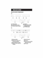
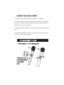
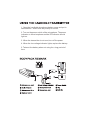
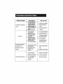
PDWM2800
User Manual
This wireless microphone system uses the UHF band.
It’s perfect for use on performance stages, assembly
halls, and karaoke bars.
You can use this product with lapel mics or handheld
microphones.
Please read this manual carefully for proper operation.
Read this before operating your unit:
1. Please read this manual carefully before
using. Keep it in a safe place for future
reference.
2. Do not expose the unit to rain or an
environment where it may be splashed with
water. This could result in fire or electric shock.
3. Do not force on switches, knobs, or cords.
When moving, first turn off the power.
4. Do not attempt to clean the unit with chemical
solvents; this might damage the surface. Use a
clean, dry cloth.
5. To prevent receiver damage, please turn off
power during electrical storms.
6. The voltage must be the same that is specified
on the unit.
RECEIVER
RECEIVER REMARK
A:
CD
Power Switch
@ Audio Volume Control
(3) RF&Audio Signal Display
®
Antenna
® Mixed Audio Outlet&
Separate Outlet
<ID DC Power Input
B:
Q) Power Switch
@ Switchorer of R F and
Antenna indicator
@AudioSignallndicator
® Digita Tube Frequency
Display
®Audio Volume
<IDAntenna
(j) Mixed Audio Outlet&
Separate Outlet
® DC input
1. Draw out the antennas and form them in a V shape.
2. Connect one end of the audio cable with the DC input jack of
the receiver and the other to the microphone input port of an
audio mixer or power amplifier.
3. Connect the AC adaptor to the DC port and then plug into the
wall.
4. Press the switch of the receiver to turn on the receiver, and
then turn on the power supply.
¢
¢
¢
¢
¢
¢
¢
1. Open the handheld microphone battery cover and put in
two batteries – make sure the polarity is correct.
2. Turn on the power switch of the microphone. The power
indicator on the microphone and the RF indicator should
light on.
3. When the transmitter is not used, turn off the power.
4. When the low voltage indicator lights, replace the battery.
5. Take out the battery when not using for a long period of
time.
STANDARD PARTS
TROUBLESHOOTING
BREAKDOWN
REASONS
SOLUTION
1. The transmitter does
The power indicator is
naton
2.
not load the battery,
and the battery no
power or the battery
polarity is wrong.
The power jack of rece-
1. Load in a new battery
2. Connect receiver's
iver is not attached
3. Tum on the power of
power
power.
3•. oower switch is off
1. the transmitter is
2.
iver has not been
connected.
No voice
The distance between
2. Joint the receiver and
ioudspeaker together.
3. Tum up the volume
receiver or the loudspeaker is too low.
4. the transmitter is
far from the receiver.
4. Do not make the
1.
2.
enough
The voice is distortion
1. Tum on the transmitter
3. the volume of the
the receiver and
transmitter is not far
noitumed on.
the AF cord of rece-
receiver.
Do not draw out the
antenna fully.
The power of the
battery is not
enough.
bBnsmittar far fNlSy
from the receiver.
1. Draw out the antenna
fully.
2.
Replace a new battery.
Replace a new battery.
1.
The power of the
1.
battery is not enough.
2. Put the loudspeaker
2.
The loud speaker is
too near to the
receiver.
far from the receiver.
PARAMETER
RECEIVER
Frequency Range:
Sensitivity:
Dynamic Range:
Signal-to-Noise:
Image Rejection:
Audio Frequency Response:
System Distortion:
Audio Output Level:
Power supply:
Current Consumption:
480-S60Mhz
<2UV (12dB SINAD)
>80dB
>80dB
>60dB
80-12S00HZ
<1%
700mV(600D)
DC12V-17V/600MA
< 400mA
TRANSMITTER
Maximum Deviation Range:
Frequency Stability:
RF Output Power:
RF Rejection:
Current Consumption:
Operate Range:
Battery:
PYLE MISCELLANEOUS PARTS
SO KHz (Max)
±O.OOS%
<40mW
>40dB
<100mA
60-80M
1.SVX2 AA
MISC ACCESSORIES