1
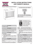
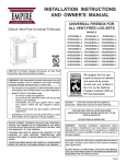
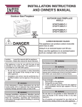
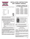
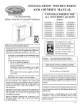
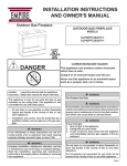
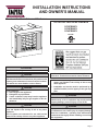
INSTALLATION INSTRUCTIONS
AND OWNER'S MANUAL
EMPIRE
Comfort Systems
Premium Ventless Universal Fireboxes
OUTDOOR VENTLESS FIREBOX
OP32FB2MF-1
OP36FB2MF-1
OP42FB2MF-1
GAS-FIRED
WARNING
For Outdoor Use Only.
WARNING
If not installed, operated and maintained in accordance
with the manufacturer's instructions, this product could
expose you to substances in fuel or from fuel combustion which can cause death or serious illness.
WARNING
If you smell gas:
1. Shut off gas to the appliance.
2. Extinguish any open flame.
3. If odor continues, keep away from the appliance
and immediately call your gas supplier or fire department.
WARNING
Do not store or use gasoline or other flammable vapors and liquids in the vicinity of this or any other
appliance.
An LP-cylinder not connected for use shall not be
stored in the vicinity of this or any other appliance.
Installer: Leave this manual with the appliance.
Consumer: Retain this manual for future reference.
— Do not store or use gasoline or other flammable
vapors and liquids in the vicinity of this or any
other appliance.
— Installation and service must be performed by a
qualified installer, service agency or the gas supplier.
WARNING
If the information in these instructions are not followed exactly, a fire or explosion may result causing
property damage, personal injury or loss of life.
WARNING
Improper installation, adjustment, alteration, service
or maintenance can cause injury or property damage.
Read the installation, operating and maintenance
instructions thoroughly before installing or servicing
this equipment.
Page 1
TABLE OF CONTENTS
SECTIONPAGE
Important Safety Information.....................................................................................3
Introduction............................................................................................................4-5
Clearances................................................................................................................6
Combustible Materials...............................................................................................6
Outer Firebox Dimensions........................................................................................7
Inner Firebox Dimensions.........................................................................................7
Planning Installation..................................................................................................8
Firebox Framing and Installation...............................................................................9
Gas Line Connection...............................................................................................10
Master Parts Distributor List.................................................................................... 11
How To Order Repair Parts..................................................................................... 11
Parts List.................................................................................................................12
Parts View...............................................................................................................13
Warranty Terms.......................................................................................................14
Appliance Service History.......................................................................................15
Page 2
29083-1-0612
IMPORTANT SAFETY INFORMATION
•
Installer: Please leave these instructions with the owner for
future reference
•
This unit complies with ANSI Z21.97/CSA 2.41 and CSA 4.96
U.S. for Outdoor Gas Fireboxs.
•
Children and adults should be alerted to the hazard of high
surface temperature and should stay away to avoid burns
or clothing ignition.
•
Young children should be carefully supervised when they
are in the same area with the appliance.
•
Clothing or other flammable materials should not be hung
from the appliance, or placed on or near the appliance.
•
Installation and repair should be done by a QUALIFIED
SERVICE PERSON. This appliance should be inspected
before use and at least annually by a professional service
person. More frequent cleaning may be required due to
insects, pollen build up, dust, etc. It is imperative that
the control compartments, burners, and circulating air
passageways of the appliance be kept clean.
•
Do not place trash, logs, or other articles on the log set
during operation.
•
During manufacturing, fabricating and shipping, various
components of this appliance are treated with certain oils,
films or bonding agents. These agents are not harmful, but
may produce annoying smoke and smells as they are burned
off during initial operation of the appliance. This is a normal
temporary occurrence.
•
WARNING: Keep appliance area clear and free from
combustible materials, gasoline and other flammable vapors
and liquids.
•
WARNING: Any modification to this gas log set or to controls
can be dangerous. Improper installation or use of the gas
log set can cause serious injury or death from fire, burns,
explosion or carbon monoxide poisoning.
•
Follow all local codes regarding installation, combustion
and ventilation air or in the absence of local codes follow
the National Fuel Gas Code ANSI Z223.1 (US installation), or
CAN/CGA-B149, installation Code (Canada installation).
•
Do not operate this log set with glass doors in the closed
position. A firebox screen must be in place when the log
set is burning.
•
Inspect the hose before each use of the appliance.
•
•
The hose assembly must be replaced prior to the appliance being into operation if there is evidence of excessive abrasion or wear, or if the hose is damaged.
Inspect the burner at least once a year.
Do Not Operate THIS APPLIANCE With Glass Doors Closed.
DANGER: Indicates a hazardous situation which, if not
avoided, will result in death or serious injury.
WARNING: Indicates a hazardous situation which, if
not avoided, could result in death or serious injury.
CAUTION: Indicates a hazardous situation which, if not
avoided, could result in minor or moderate injury.
NOTICE: Addresses practices not related to personal injury.
•
•
•
•
•
•
Children and adults should be alerted to the hazards of
high surface temperatures and should stay away to avoid
burns or clothing ignition.
Young children should be carefully supervised when they
are in the same area as the appliance.
Clothing or other flammable material should not be placed
on or near the appliance.
Do not place trash or other articles on the log set during
operation.
During manufacturing, fabricating and shipping, various
components of this appliance are treated with certain oils,
films or bonding agents. These bonding agents are not
harmful but may produce annoying smoke and smells as
they are burned off during initial operation of the appliance.
This is a normal temporary occurrence.
Keep burner and control compartment clean.
29083-1-0612
•
•
•
•
•
Installation and repair should be done by a qualified
service person. The appliance should be inspected
before use and at least annually by a qualified service
person. More frequent cleaning may be required due to
excessive lint from carpeting, bedding materials, etc. It
is imperative that control compartments, burners and
circulating air passageways of the appliance be kept
clean.
Do keep the appliance area clear and free from combustible
material, gasoline and other flammable vapors and
liquids.
A yearly examination and cleaning of the venting system
of the solid-fuel burning firebox must be performed by a
qualified agency.
Do make a periodic visual check of pilot and burners.
Clean and replace damaged parts.
Do not use this appliance if any part has been under
water. Immediately call a qualified service technician
to inspect the appliance and to replace any part of the
control system and any gas control which has been under
water.
Page 3
INTRODUCTION
Instructions to Installer
1. Installer must leave instruction manual with owner after
installation.
2. Installer must have owner fill out and mail registration card
supplied with this firebox.
Always consult your local Building Department regarding regulations,
codes or ordinances which apply to the installation of an ventless
room heater.
*Aftermarket: Completion of sale, not for purpose of resale, from
the manufacturer.
This appliance is only for use with the type of gas indicated on the
rating plate.
WARNING
Any change to this appliance or its controls can
be dangerous.
Improper installation or use of the appliance can cause serious injury or death from fire, burns, explosion or carbon
monoxide poisoning.
This series is design certified in accordance with American National
Standard Z21.97 as an Outdoor Ventless Firebox and should be
installed according to these instructions.
Note: This firebox has been tested and approved up to 50,000 BTU’s.
DO NOT USE WITH LOG SETS OVER 50,000 BTU’s.
Any alteration of the original design, installed other than as
shown in these instructions is the responsibility of the person
and company making the change.
Important
All correspondence should refer to complete Model Number, and
Serial Number.
Moisture Resistance
This outdoor firebox will shed moderate amounts of water, but is
not waterproof. Water and condensing water vapor may enter the
chase under certain conditions.
The firebox will not perform as an exterior wall. Moisture penetration
must be considered for construction that places the firebox in structure
walls or on moisture sensitive surfaces.
When installed on exterior walls: Empire Comfort Systems
recommends the firebox chase be constructed outside the structure's
weather envelope. Where the platform meets the wall, use a flashing
detail similar to that required for attached decks. Chase platforms,
including hearths should slope away from the structure at 1/4 in per
foot. The firebox can be shimmed level.
When installed on surfaces where water may collect or cause
damage: Empire Comfort Systems recommends a slope of 1/8 in
to 1/4 in per foot towards the drain port suggested. The firebox can
be shimmed level.
Hearths should slope away from the front of the firebox and chase
at 1/8 in to 1/4 in per foot. Metal safety strips must be on top of
any combustible hearth materials used for moisture management.
Page 4
Screened Porch Installation
The firebox may be installed safely and is design certified by CSA
to be installed in a screen porch with the following guidelines.
Minimum Porch Area
96 sq. feet (9 sq m)
Minimum Ceiling Height
92" (234 cm)
Minimum of two (2) walls must be screened
Minimum top of screen height, side walls
6'6" (198 cm)
Minimum screen area
64 sq. feet (6 sq m)
Installation on Rugs and Tile
If this appliance is installed directly on carpeting, tile or other
combustible material other than wood flooring the appliance shall
be installed on a metal or wood panel extending the full width and
depth of the appliance.
The base referred to above does not mean the fire-proof base as
used on wood stoves. The protection is for rugs that are extremely
thick and light colored tile.
Solid-fuels shall not be burned in a masonry or UL 127 factory-built
firebox in which a ventless room heater is installed.
Qualified Installing Agency
Installation and replacement of gas piping, gas utilization equipment
or accessories and repair and servicing of equipment shall be
performed only by a qualified agency. The term "qualified agency"
means any individual, firm, corporation or company which either in
person or through a representative is engaged in and is responsible for
(a) the installation or replacement of gas piping or (b) the connection,
installation, repair or servicing of equipment, who is experienced in
such work, familiar with all precautions required and has complied
with all the requirements of the authority having jurisdiction.
State of Massachusetts: The installation must be made by
a licensed plumber or gas fitter in the Commonwealth of
Massachusetts.
The installation must conform with local codes or, in the absence of
local codes, with the National Fuel Gas Code, ANSI Z223.1.*
*Available from the American National Standards Institute, Inc. 1430
Broadway, New York, N.Y. 10018.
29083-1-0612
INTRODUCTION
•
When the appliance is connected to a fixed piping system,
the installation must conform with local codes, or in the absence of local codes with the National Fuel Gas Code, ANSI
Z223.1/NFPA 54, or International Fuel Gas Code.
•
When installed, the appliance must be electrically grounded
in accordance with local codes, or in the absence of local
codes with the National Electrical Code, ANSI/NFPA 70, if
applicable.
•
Solid fuels shall not be burned in this appliance.
•
The maximum gas inlet supply pressure is 13" for LP and
10.5" for NAT.
•
For appliances for fixed fuel piping system and equipped
with an appliance gas pressure regulator, the required manifold pressure in inches water column: 10" for LP and 3.5"
NAT.
•
For appliances for fixed fuel piping system and equipped
with an appliance gas pressure regulator, the appliance and
its individual shutoff valve must be disconnected from the
gas supply piping system during any pressure testing of that
system at test pressures in excess of 1/2 psi (3.5 kPa).
The appliance must be isolated from the gas supply piping
system by closing its individual manual shutoff valve during
any pressure testing of the gas supply piping system at test
pressures equal to or less than 1/2 psi (3.5 kPa).
For an appliance designed for use with a non-disposable selfcontained LP-gas supply system:
•
Propane cylinders may be acceptable for use with the appliance provided they are compatible with the appliance
retention means.
•
LP-gas supply cylinder must be constructed and marked
in accordance with the U.S. Department of Transportation
(D.O.T.) Specifications for LP-Gas Cylinders, or the Standard for Cylinders, Spheres and Tubes for Transportation
of Dangerous Goods and Commission, CAN/CSA-B339 as
applicable.
•
LP-gas supply cylinders between 4 and 40 pounds must
have an overfill prevention device.
•
LP-gas supply cylinder must have a connection device compatible with the connection of the appliance.
•
If the appliance is equipped with a CGA No. 600 Cylinder
Connection Device, the cylinder must be disconnected when
the appliance is not in use.
•
If appliance is to be permanently connected to a gas piping
system from a remote supply tank, installation must be in accordance with local codes or, in the absence of local codes,
with the National Fuel Gas Codes ANSI Z223.1/NFPA 54.
Enclosures for LP-gas supply cylinders shall be ventilated by
openings at the level of the cylinder valve and at floor level. The
effectiveness of the opening(s) for purposes of ventilation shall
be determined with the LP-gas supply cylinder(s) in place. This
shall be accomplished by one of the following.
a. One side of the enclosure shall be completely open; or
b. For an enclosure having four sides, a top and a bottom:
1. At least two ventilation openings at cylinder valve
level shall be provided in the side wall, equally
sized, spaced at 180 degrees (3.14rad), and unobstructed. Each opening shall have a total free area
of not less than 1/2 square inch per pound (2.3 sq.
cm/kg) of stored fuel capacity and not less than a
total free area of 10 square inches (64.5 sq. cm).
2. Ventilation opening(s) shall be provided at floor
level and shall have a total free area of not less
than 1/2 square inch per pound (3.2 sq. cm/kg) of
stored fuel capacity and not less than a total free
area of 10 square inches (64.5 sq. cm). If ventilation openings at floor level are in a side all, there
shall be at least two openings. The bottom of the
openings shall be at floor level and the upper edge
no more than 5 inches (127 mm) above the floor.
The openings shall be equally sized, spaced at 180
degrees (3.14 rad) and unobstructed.
3. Every opening shall have minimum dimensions so
as to permit the entrance of a 1/8 inch (3.2 mm)
diameter rod.
•
Cylinder valves shall be readily accessible for hand operation. A door on the enclosure to gain access to the cylinder
valves is acceptable, provided it is non-locking and can be
opened without the use of tools.
•
There shall be a minimum clearance of 2 inches (51 mm)
between the lower surface of the floor of the LP-gas supply
cylinder enclosure and the ground.
•
The design of the appliance shall be such that (1) the LP-gas
supply cylinder(s) can be connected, disconnected and the
connections inspected and tested outside the cylinder enclosure; and (2) those connections which could be disturbed
when installing the cylinder(s) in the enclosure can be leak
tested inside the enclosure;
Cleaning Instructions
This appliance is built using mostly high-grade stainless steel to
resist rust-through. In outdoor applications, all stainless steel will
develop a dull patina and, depending on the local environment
and on the materials used in the installation, may develop some
surface oxidation (rust). This does not affect the performance
of the firebox, and does not require any action to correct. If you
prefer keeping your firebox front looking factory-fresh, clean it as
required with stainless steel cleaner.
When installation application includes highly acidic applications
such as mortar or stone etching, do not remove the protective
PVC film from the stainless steel until after this application is
complete. Once the film has been removed we recommend that
the appliance be cleaned with a stainless steel cleaner immediately.
Please note that areas where the film has been formed (corners,
hems, etc.) may require extra cleaning due to the properties of
the film. Ensure that all protective film has been removed from
the firebox prior to burning the appliance.
29083-1-0612
Page 5
CLEARANCES
Minimum Wall and Ceiling Clearances (Figure 1)
Mantel Clearances
12”
10”
Sidewall and Back Clearances: The clearance from the
inside of the firebox to any combustible wall should not be
less than 2".
MANTEL
Ceiling Clearances: The ceiling height should not be less
than 36" from the top of the hood.
Mantel Clearances: Ventless firebox models must use the
hood supplied with the firebox. If a combustible mantel is
installed, it must meet the clearance requirements detailed
above.
COMBUSTIBLES
ALLOWED
8”
6”
27 3/4”
4”
27”
2”
24 1/4”
21 1/2”
18 3/4”
16”
HOOD
Figure 1
COMBUSTIBLE MATERIALS
Do not attach combustible material to the mantel of your firebox.
This is a fire hazard.
No greeting cards, stockings or ornamentation of any type should
be placed on or attached to the firebox. This is a heating appliance.
The flow of heat can ignite combustibles.
Figure 2
Figure 3
Page 6
29083-1-0612
OUTER FIREBOX DIMENSIONS
E
G
DELUXE
FLUSH
A
I
J
H
K
F
B
C
D
L
INDEX
LETTER
OP32FB2MF
OP36FB2MF
OP42FBMF
A
35 5/8”
37 5/8"
37 5/8"
B
34 1/2”
39 1/2"
43 1/2"
C
17 7/16”
19 13/16"
19 13/16"
D
29”
33"
37"
E
33”
35"
35"
F
31”
36"
40"
G
22 3/8”
24 3/8"
24 3/8"
H
1 1/4”
6 1/8"
6 1/8"
I
31 1/2”
30 9/16"
30 9/16"
J
8 3/8”
8 3/8"
8 3/8"
K
5 3/4”
5 3/4"
5 3/4"
L
31 13/16”
36 3/16"
38 3/16"
M
63 3/8”
72 3/8"
76 3/8"
M
INNER FIREBOX DIMENSIONS
B
E
TOP VIEW
A
29083-1-0612
SIDE VIEW
D
INDEX
LETTER
OP32FB2MF
OP36FB2MF
OP42FBMF
A
29 1/8”
34 1/8”
38 1/8”
B
23 5/8”
27 5/8”
31 5/8”
C
12 7/8”
15 5/16”
15 5/16”
D
17 5/16”
18 3/4”
18 3/4”
E
20 9/16”
22 9/16”
22 9/16”
C
Page 7
PLANNING INSTALLATION
In planning the installation for the firebox, it is necessary to determine
where the unit is to be installed and whether optional accessories
are desired. Gas supply piping should also be planned at this time.
The firebox can be mounted on any of these surfaces:
1. A flat non-combustible surface.
2. A raised platform non-combustible material.
3. Four (4) corners of the firebox so contact is made on all four
perimeter edges on the bottom of the unit.
(Example: Four (4) concrete masonry blocks.)
If the firebox is installed directly on carpeting, tile or other combustible
material other than wood flooring, it should be installed on a metal
or wood panel extending the full width and depth of the unit.
Installing the Hood
A stainless steel hood is furnished with each outdoor firebox. The
hood MUST be installed before the firebox is used. Failure to do
so may create a possible fire hazard.
Finishing
Hearth extensions are recommended, not a requirement for these
gas fireboxs.
At this point, you should have decided what components to include
in your installation, and where the firebox is to be located. If this
has not been done, stop and consult your dealer for assistance
with this planning.
This firebox is intended for installation on an outdoor patio or
in your yard. This firebox shall be used only outdoors in a well
ventilated space and shall NOT be used in a building, garage, or
other enclosed area.
It is recommended that this firebox be installed in a “sheltered” area.
Direct wind will cause an erratic flame and possible pilot or main
burner outage. This erratic flame could also lead to excessive black
soot. These issues are nuisance issues rather than a safety issues.
Typical installation may include covered patio, screened porch,
gazebo or an outside wall of a house.
•
•
Minimum porch area – 96 square feet
Minimum ceiling height – 82 inches
Minimum of two walls to be open or screened to the following
guidelines.
• Minimum screen area – 64 square feet
• Minimum top of screen height (side walls) – 70 inches
Page 8
Figure 4
Cleaning Instructions
This appliance is built using mostly high-grade stainless steel to
resist rust-through. In outdoor applications, all stainless steel will
develop a dull patina and, depending on the local environment
and on the materials used in the installation, may develop some
surface oxidation (rust). This does not affect the performance of
the firebox, and does not require any action to correct. If you prefer keeping your firebox front looking factory-fresh, clean it as required with stainless steel cleaner.
When installation application includes highly acidic applications
such as mortar or stone etching, do not remove the protective PVC
film from the stainless steel until after this application is complete.
Once the film has been removed we recommend that the appliance be cleaned with a stainless steel cleaner immediately.
29083-1-0612
FIREBOX FRAMING AND INSTALLATION
Firebox framing can be built before or after the firebox is set in place.
Framing should be positioned to accommodate wall covering and
firebox facing material.
Note: Finish must be concrete board or noncombustible material.
1. Place firebox in framing opening.
2. Using the four (4) nailing flanges provided with the firebox,
attach two (2) flanges on each side. Attach flanges through
pre-punched holes. Additional hole locations will be used for
different finishing material with thicknesses of 1/2”, 5/8” and
3/4”. Attach these flanges with screws provided, two (2) per
nailing flange.
3. Nailing flanges should fit directly against non-combustible
framing material. Use at least one (1) nail per tab to secure in
place.
STEEL STUD OR STEEL
FRAMING REQUIRED.
COMBUSTIBLE MATERIAL
NOT ALLOWED ADJACENT
TO FIREBOX.
NOTE: FINISH MUST BE
CONCRETE BOARD OR
NON-COMBUSTIBLE MATERIAL.
SCREW OR OTHER SUITABLE FASTENER
Figure 5
2X4
NON-COMBUSTIBLE
HEADER
OP32FB
OP36FB
OP42FB
"A"
36 1/8”
38 1/2"
38 1/2"
"B"
35”
40"
44"
"C"
17”
19 3/8"
19 3/8"
Attention: Add 1" to "A" Dimensions when using drain tray.
Figure 7
NON-COMBUSTIBLE
FINISHED WALL
OR MANTEL
12”
MIN.
Figure 6
29083-1-0612
Page 9
GAS LINE CONNECTION
The firebox is designed to accept a 3/8-inch gas line for an approved
ventless gas logset. Have the line installed by a qualified service
person in accordance with all building codes. Consult local building
codes to properly size the gas supply line leading to the 3/8-inch
hook-up at the unit. The state of Massachusetts requires that a
flexible appliance connector cannot exceed three feet in length.
Gas access holes are provided on both sides of the firebox. See
Figure 8. Carefully remove the knockout in the refractory brick
panel using a large standard screwdriver and hammer. First, place
screwdriver in groove next to plug and pry sideways to pop out
main plug. Then remove the remaining concrete in hole with gentle
tapping with ball peen hammer and/or screwdriver. A masonry drill
and bit may also be used to create a clean hole for the gas line to
pass through. See Figure 9.
GAS ACCESS HOLES
After the brick panel knockout is removed, the firebox wrap may
have a round metal knockout that must be removed also. Use a
screwdriver to punch out the metal knockout.
Check gas type. Use only the gas type indicated on the gas log
set rating plate. If the gas listed on the plate is not your type of gas
supply, DO NOT INSTALL. Contact your dealer for proper model.
Always use an external regulator for all LP fireboxes to reduce the
supply tank pressure to a maximum of 14" w.c. This is in addition
to the regulator fitted to the log set.
Figure 8
WARNING: CONNECTION DIRECTLY TO AN UNREGULATED
L.P. TANK CAN CAUSE EXPLOSION.
Install only a ANSI Z21.97.1/CSA 2.41 ventless log set into this
firebox.
Figure 9
Page 10
29083-1-0612
MASTER PARTS DISTRIBUTOR LIST
To Order Parts Under Warranty, please contact your local Empire dealer. See the dealer locator at www.empirecomfort.
com. To provide warranty service, your dealer will need your name and address, purchase date and serial number, and the
nature of the problem with the unit.
To Order Parts After the Warranty Period, please contact your dealer or one of the Master Parts Distributors listed below.
This list changes from time to time. For the current list, please click on the Master Parts button at www.empirecomfort.com.
Please note: Master Parts Distributors are independent businesses that stock the most commonly ordered Original
Equipment repair parts for Heaters, Grills, and Fireboxs manufactured by Empire Comfort Systems Inc.
Dey Distributing
1401 Willow Lake Boulevard
Vadnais Heights, MN 55101
Phone: 651-490-9191
Toll Free: 800-397-1339
Website: www.deydistributing.com
Parts: Heater, Hearth and Grills
East Coast Energy Products
10 East Route 36
West Long Branch, NJ 07764
Victor Division of F. W. Webb Company
200 Locust Street
Hartford, CT 06114
Phone: 732-870-8809
Toll Free: 800-755-8809
Fax: 732-870-8811
Website: www.eastcoastenergy.com
Parts: Heater, Hearth and Grills
Phone: 860-722-2433
Toll Free: 800-243-9360
Fax: 860-293-0479
Toll Free Fax: 800-274-2004
Websites: www.fwwebb.com & www.victormfg.com
Parts: Heater, Hearth and Grills
HOW TO ORDER REPAIR PARTS
Parts Not Under Warranty
Parts can be ordered through your Service Person, Dealer, or a Master Parts Distributor. See this page for the Master Parts Distributors list. For best results, the service person or dealer should order parts through the distributor. Parts can be shipped directly to the
service person/dealer.
Warranty Parts
Warranty parts will need a proof of purchase and can be ordered by your Service Person or Dealer. Proof of purchase is required for
warranty parts.
All parts listed in the Parts List have a Part Number. When ordering parts, first obtain the Model Number and Serial Number from the
name plate on your equipment. Then determine the Part Number (not the Index Number) and the Description of each part from the following illustration and part list. Be sure to give all this information . . .
Appliance Model Number
Appliance Serial Number
Part Description
Part Number
Type of Gas (Propane or Natural)
Do not order bolts, screws, washers or nuts. They are standard hardware items and can be purchased at any local hardware store.
Shipments contingent upon strikes, fires and all causes beyond our control.
29083-1-0612
Page 11
PARTS LIST
Use Only Manufacturer’s Replacement Parts. Use of Any Other Parts Could Cause Injury Or Death.
Page 12
PART No.
Index
No.
OP32FB2MF
OP36FB2MF
OP42FB2MF
1
17149
17247
17247
Description
Top Standoff
2
28987
27781
27782
Firebox Front
3
10554
10554
10554
Nailing Flange
4
R10387
R10391
R10391
Liner, Side - Left
5
R10388
R10392
R10392
Liner, Side - Right
6
R10386
R10390
R10393
Liner, Rear
7
27792
27792
27792
Liner Bracket - Bottom
8
20447
20447
20447
Liner Bracket - Top
9
29068
20234
20237
Hood
10
R11107
R11036
R11037
Curtain, Rod
11
R11108
R10765
R10765
Curtain, Screen
12
R11104
R11105
R11106
Liner, Bottom
29083-1-0612
PARTS VIEW
10
1
3
6
5
11
8
8
2
3
7
4
9
12
29083-1-0612
Page 13
WARRANTY TERMS
Empire Comfort Systems Inc. warrants this hearth product to be free from defects at the time of manufacture and for the
periods specified below. Hearth products must be installed by a qualified technician and must be maintained and operated
safely, in accordance with the instructions in the owner’s manual. This warranty applies to the original purchaser only and
is not transferable. All warranty repairs must be accomplished by a qualified gas appliance technician.
Limited Five-Year Parts & Labor Warranty - All Components (Except Remote Controls and Thermostats)
Should any part fail because of defective workmanship or material within five years from the date of purchase, Empire
will repair or, at Empire’s option, replace the defective part.
Within five years from the date of purchase, Empire will pay reasonable labor to have that defect repaired or replaced at
Empire’s option.
Limited One-Year Parts Warranty - Remote Controls and Thermostats
Should any remote control or thermostat part fail because of defective workmanship within one year from the date of
purchase, Empire will repair or replace at Empire’s option.
Duties Of The Owner
The appliance must be installed by a qualified installer and operated in accordance with the written instructions furnished
with the appliance.
Ready access to the appliance for service is the responsibility of the owner.
Travel, diagnostic costs and freight charges on warranted parts to and from the factory is the responsibility of the owner.
A bill of sale, cancelled check, or payment record should be kept to verify purchase date and establish warranty period.
What Is Not Covered
This warranty does not cover damages that might result from the use, misuse, or improper installation of this appliance.
This warranty does not cover claims that do not involve defective workmanship or materials.
This warranty does not cover unauthorized service or parts replacements will not be covered.
How To Get Service
To make a claim under this warranty, please have your receipt available and contact your installing dealer. Provide the
dealer with the model number, serial number, type of gas and purchase verification. The installing dealer is responsible for
providing service and will contact the factory to initiate any warranted parts replacements. Empire will make replacement
parts available at the factory. Shipping expenses are not covered.
If, after contacting your Empire dealer, service received has not been satisfactory, contact: Consumer Relations Department, Empire Comfort Systems Inc., P.O. Box 529, Belleville, Illinois 62222, or send an e-mail to [email protected]
with “Consumer Relations” in the subject line.
Your Rights Under State Law
This warranty gives you specific legal rights, and you may also have other rights, which vary from state to state.
Page 14
29083-1-0612
APPLIANCE SERVICE HISTORY
Date
Dealer Name
29083-1-0612
Service Technician Name
Service Performed/Notes
Page 15
EMPIRE
Comfort Systems
Empire Comfort Systems Inc.
918 Freeburg Ave. Belleville, IL 62220
If you have a general question about our products, please e-mail us at
[email protected].
If you have a service or repair question, please contact your dealer.
www.empirecomfort.com
Page 16
29083-1-0612