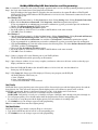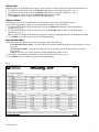
1
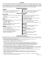
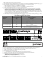
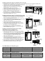
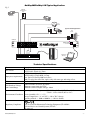
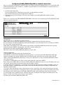
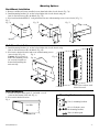
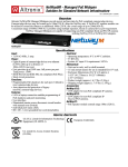
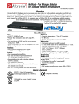
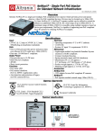
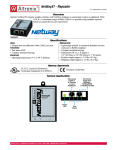
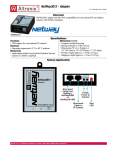
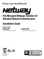
Power over the Ethernet
PoE Managed Midspan Solution for
Standard Network Infrastructure
Installation Guide
Models Include:
NetWay8MNetWay16M
- Eight (8) Port PoE Midspan Injector
DOC#: NETM
Rev. 052110
- Sixteen (16) Port PoE Midspan Injector
More than just power.™
Overview:
Altronix NetWay8M/NetWay16M Managed Midspans provide power and pass data for PoE compliant cameras/edge devices. Cameras/edge devices may be located up to 100m from the NetWay unit. A NetWayXT/NetWayXTX repeater module can be utilized to extend the distance an additional 100m for a total range of up to 200m. A maximum range of 600m
is possible using multiple repeaters, based on camera/device port requirement. NetWay Managed Midspans are capable of
supporting non-PoE compliant fixed and PTZ IP cameras utilizing NetWay1512 or NetWay3012 adapters.
NetWay8M:
NetWayM Specifications:
NetWay16M:
Agency Listings:
Common Specifications:
Features:
• Eight (8) ports of cameras/edge devices over ethernet (CAT5) cable up to a distance of 100m per port.
• 115VAC 60Hz, 3 amp (NetWay8M).
• UL/CUL Listed for Information Technology Equipment (UL 60950-1).
• UL Listed for Access Control Systems (UL294).
• CE approved.
Power:
• Unit supplies PoE output voltage (55V), and up to 30W max. full power per port.
Total power: NetWay8M - 150W,
NetWay16M - 300W.
• IEEE 802.3af and IEEE 802.3at compliant (PoE Plus).
• All output circuits are power-limited.
• Short circuit protection.
Functions:
• Programmble PoE shutdown for each port. Utilized to
reset cameras/edge devices
(see Technical Specifications pg. 5).
• PoE manual shutdown (For UL 60950-1 applications
only) (see Technical Specifications pg. 5).
• Auto detection and protection of legacy
non-PoE cameras/edge devices.
• Sixteen (16) ports of cameras/edge devices over ethernet (CAT5) cable up to a distance of 100m per port.
• 115VAC 60Hz, 4.9 amp (NetWay16M).
• LAN or laptop connection enables programming of
PoE shutdown and port monitoring.
• User interface (Fig. 6, pg. 7).
• Illuminated master power disconnect circuit breaker
with manual reset (switch).
• Individual port status LEDs.
• IEC 320 - 3-wire grounded line cord (detachable).
• Unit can be rack or shelf mounted.
• 1U rack mount chassis for use in standard EIA 19” rack.
Accessories:
NetWay1512:
• 15W adapter for non-PoE compliant IP cameras.
(For UL 60950-1 applications only).
NetWay3012:
• 25W adapter for non-PoE compliant IP
fixed or PTZ cameras.
(For UL 60950-1 applications only).
NetWayXT:
• PoE repeater module extends range 100m
(For UL 60950-1 applications only).
NetWayXTX:
• PoE+ repeater module extends range 100m.
Installation Instructions:
Wiring methods shall be in accordance with the National Electrical Code (ANSI/NFPA70), local codes, and the authorities
having jurisdiction. NetWayM is not intended to be connected to outside plant leads. These products are for indoor use only
and must be installed within the protected premises.
1. Attach mounting brackets to NetWayM unit for rack or wall mount installation (Figs. 7 or 8, pg. 10).
Affix rubber pads to NetWayM for shelf installation (Fig. 9, pg. 10).
2. Secure the unit in a rack or place unit on a shelf as desired.
Note: The following factors should be taken into consideration when installing these rack mount units:
a. The unit is to be installed in a space where the maximum ambient temperature does not exceed 104ºF (40ºC).
b. Take care to ensure there is sufficient air flow around the unit and that obstructions do not impede it.
c. When mounting units in rack, take care to avoid uneven loading which can cause a hazardous condition.
3. Set illuminated master power disconnect circuit breaker to the (OFF) position (Fig. 1g, pg. 3).
4. Plug the grounded AC line cord (included) into the IEC 320 connector of the NetWayM unit (Fig. 1h, pg. 3). Plug unit into a reliable earth grounded socket. When using multiple units the sum of the individual name plate ratings should not exceed the supply circuit rating. Do not connect to a receptacle controlled by a switch.
5. Connect structured cables from port marked [IN] on NetWayM to the corresponding inputs of an ethernet switch or
video server (Fig. 1b, pg. 3, Fig. 5, pg. 5).
Note: All cabling and wire must be UL Listed and/or Recognized wire suitable for their application.
6. Connect structured cables from port marked [OUT] on NetWayM to PoE compliant camera/edge devices
(Fig. 1a, pg. 3, Fig. 5, pg. 5).
Note: For UL294 applications the products are to be tested as part of a complete Access Control System and in
accordance with UL Listed Access Control Devices.
- 2 -
NetWay8M/NetWay16M
Note: All interconnected devices must be UL Listed.
7. Upon completion of wiring set illuminated master power disconnect circuit breaker to the RESET (ON) position (Fig. 1g, pg. 3).
8. Port status LEDs on the NetWayM will initialize when PoE devices are connected as follows:
- LED will illuminate when devices are IEEE 802.3af compliant.
- LED will blink once and illuminate when devices are IEEE802.3at compliant (PoE Plus).
9. To utilize the PoE shutdown feature it is necessary to do the following:
a. Connect a device that will provide a low voltage trigger input (see Technical Specifications pg. 5) to terminals
marked [+ --- , PoE Shutdown] on the NetWayM (Fig. 1e, pg. 2). When voltage is applied, the PoE shutdown
enabled PoE port(s) will drop to zero volts. Removing the low voltage trigger input at the [+ --- , PoE shutdown]
terminals will allow the PoE port(s) to operate normally and supply power to PoE compliant devices. Power will
reset in approximately 4 seconds. Although there is no output voltage to power PoE devices during shutdown, data
signals may still be present on the data pair lines of the structured cable.
b. Individual ports must be programmed utilizing the user interface (see User Interface and Programming, pgs. 6 & 7).
Port Status and LED Flash Codes:
Port Status
All Ports Off
Port Off
Port On
Class 4 detection Port
Non-compliant Device
Port Overload Fault
Flash Codes
Sequential LED Port Scan
OFF
ON
Blinks 2 times
2Hz
5Hz
4 Port Overload Grouped
5Hz
8 Port Overload Grouped
5Hz
Description
No devices connected
LED OFF
LED ON
Enables power to PoE devices.
Will prevent port from turning on.
Will prevent port from turning on.
4 LEDs
Will prevent ports from turning on.
LEDs 1-8 Power Supply Overload for ports 1-8.
LEDs 9-16 Power Supply Overload for ports 9-16.
Fig. 1
+ PoE -SHUTDOWN
NetWay8M - Front Panel
1a
1b
1c
1d 1e
1f
+ PoE -SHUTDOWN
NetWay16M - Front Panel
1g
1h
AC POWER
NetWay8M & NetWay16M - Rear Panel
1a
1b
1c
1d
1e
1f
1g
1h
OUT 1-8 (NetWay8M), OUT 1-16 (NetWay16M): Structured cable to PoE compliant cameras/edge devices.
IN 1-8 (NetWay8M), IN 1-16 (NetWay16M): Structured cable to ethernet switch or video server.
LED(s) 1-8 (NetWay8M), 1-16 (NetWay16M): Port status LEDs.
Reset: Restores unit to factory settings.
+ --- , PoE Shutdown: Low voltage trigger input (see Technical Specifications pg. 5).
Ethernet: LAN or laptop connection enables NetWayM programming and status monitoring.
Illuminated master power disconnect circuit breaker (switch):
• OFF position Circuit breaker tripped Switch not illuminated.
• RESET (ON) position Switch illuminated.
IEC 320 Connector: 115VAC 60Hz (grounded line cord included).
NetWay8M/NetWay16M
-3-
Installing a NetWay1512 adapter for 12VDC IP cameras up to 13W:
1. Mount NetWay1512 in proximity to IP camera (Fig. 2, pg. 4). Affix one side of velcro (supplied) to NetWay1512
and the place the second side of the velcro in the desired location.
2. Connect structured cable from port marked [IN] on Fig. 2 - NetWay1512
NetWay1512 to any ports marked [OUT] of NetWay8M/
NetWay16M (Fig. 2, pg. 4, Fig. 1a, pg. 3).
3. Connect structured cable from port marked [OUT] on
NetWay1512 to the IP camera (Fig. 2, pg. 4).
Netway1512
4. Connect 12VDC output from NetWay1512 terminals
www.altronix.com
Structured
marked [--- 12VDC +] to the power input of the
12VDC
OUT
IN
Cable from
--- Output +
-- +
IP camera (Fig. 2, pg. 4). Polarity must be observed.
NetWay
12VDC
Output
5. Power LED indicator will illuminate on NetWay1512
Structured Cable
under normal conditions (Fig. 2, pg. 4).
from IP Camera/Device
Adapter
Power
LED
Installing a NetWay3012 adapter for 12VDC IP PTZ up to 25W:
1. Mount NetWay3012 in proximity to IP camera utilizing mounting
hole (Fig. 3, pg. 5). Use a proper fastener and/or wall anchor
when securing NetWay3012 to the wall.
2. Connect structured cable from port marked [IN] on NetWay3012
to ports marked [OUT] of NetWay8M/NetWay16M
(Fig. 3, pg. 4, Fig. 1a, pg. 3).
3. Connect structured cable from port marked [OUT] on
NetWay3012 to the IP fixed or PTZ camera (Fig. 3, pg. 4).
4. Connect 12VDC output from NetWay3012 terminals marked
[+ 12VDC ---] to the power input of the
IP camera (Fig. 3, pg. 4). Polarity must be observed.
5. Power LED indicator will illuminate on NetWay3012 under
normal conditions (Fig. 3, pg. 4).
Fig. 3 - NetWay3012
I.T.E. 43KC
Netway3012
Adapter
www.altronix.com
IN
12VDC
+ Output ---
OUT
Structured Cable
from NetWay8,
NetWay8M, NetWay16
or NetWay16M
Power LED
-- 12VDC
+ Power to
Camera
Structured Cable
from IP Camera
Installing a NetWayXT/NetWayXTX repeater module:
NetWayXT will work only with PoE devices.Fig. 4 - NetWayXT/NetWayXTX
NetWayXTX will work with PoE/PoE+ devices.
NetWayXT
1. Mount NetWayXT/NetWayXTX in desired location utilizing
the mounting hole (Fig. 4, pg. 4). Use a proper fastener and/or
wall anchor when securing NetWayXT/NetWayXTX to the wall.
NetwayXT
2. Connect structured cable from port marked [OUT] on NetWay
Structured
Repeater
Power
Cable from
LED
to port marked [IN] on the NetWayXT/NetWayXTX
NetWay8/16
(Fig. 4, pg. 4, Fig. 1a, pg. 3).
Structured Cable
to IP Camera/
3. Connect structured cable from port marked [OUT] on
Edge Device
or next
NetWayXT/NetWayXTX to the PoE/PoE+ camera/edge device
NetWayXT
or next NetWayXT/NetWayXTX repeater (Fig. 4, pg. 4).
NetWayXTX
www.altronix.com
Structured
4. Port status LEDs will illuminate on NetWayXT/NetWayXTX
Cable from
NetWay8/16
indicating the port is operational (refer to LED Definitions).
5. Power LED will illuminate indicating 12VDC output.
Power
OUT
IN
PoE/PoE+
Output
LED
Port LED definitions for NetWayXT repeater:
Status
Green LED
OFF
Indicates it is connected as 10Base-T or no link.
ON
Indicates it is connected as 100Base-TX.
Blinking
--------------------------Port LED definitions for NetWayXTX repeater:
Status
PoE/PoE+ Output LED
OFF
No PoE/PoE+ Output
ON
Normal PoE/PoE+ Output
Blinking
------- 4 -
PoE/PoE+ Input LED
No PoE/PoE+ Input
PoE/PoE+ Input
-------
Port Status
Structured
LEDs
Cable to
PoE/PoE+
Camera/Device or
next NetWayXTX
PoE/PoE+
Input
LED
Yellow LED
Indicates no link.
Indicates a link.
Indicates activity.
Yellow LED
Indicates no link.
Indicates a link.
Indicates activity.
NetWay8M/NetWay16M
NetWay8M/NetWay16M Typical Application:
Fig. 5
NetWayXT
Extends Ethernet
100m
I.T.E. 43KC
NetwayXT
Repeater
PoE Camera
www.altronix.com
Power
OUT
IN
PoE Camera
PoE +
Camera
NetWay1512
Netway1512
Typical UL294 Application:
Card
Reader
I.T.E.
43KC
Adapter
www.altronix.com
IN
OUT
12VDC
+ Output ---
12VDC
IP camera
Strike
HID Solo
NetWay8M
+ PoE -SHUTDOWN
Programming
and Status
Ethernet Switch
NVR/Network Server
Technical Specifications:
Parameter
No. of Ports
Description
NetWay8M - Eight (8) Ports.
NetWay16M - Sixteen (16) Ports.
NetWay8M: 115VAC 60Hz, 3 amp.
NetWay16M: 115VAC 60Hz, 4.9 amp.
Input power requirements
Fuse: 4A/125V (NetWay16M has 2 fuses).
Note: To reduce the risk of fire, replace only with same type and rating of fuse.
Indicators
PoE Shutdown Voltage
and Current Range
Port Status LED
5VDC to 24VDC or 12VAC to 24VAC
Minimum current: 2mA for 5VDC
Minimum current for higher voltages: 10mA
Operating Ambient Temperature: UL60950-1 - 32ºF to 104ºF (0ºC to 40ºC).
UL294 - 32ºF to 120.2ºF (0ºC to 49ºC).
Environmental Conditions Relative humidity: 85%, +/ --- 5%
Storage Temperature: --- 4º to 158ºF (--- 20º to 70ºC) Storage
Operating Altitude: --- 1000 to 10,000 ft. (--- 304.8 to 3048m).
Regulatory Compliance
NetWay8M/NetWay16M
UL/CUL Listed for Information Technology Equipment (UL 60950-1).
UL Listed for Access Control Systems (UL 294).
CE approved
-5-
NetWay8M/NetWay16M User Interface and Programming:
Note: A constant PC connection is not required for proper operations and is used as a local programming/monitoring tool only.
Step 1.Set Local Area Connection of your laptop to Static IP mode.
Static IP address of the laptop must be assigned to the same network as the current IP address of NetWay8M/
NetWay16M. The default IP address of NetWayM units is 192.168.168.168. This manual assumes that it has not been changed by user.
For Windows XP:
a.Open Network Connections by clicking Start button, then clicking Settings, then clicking Network Connections.
b.Right click the Local Area Connection. Click Properties. Administrator permission required
If you are prompted for an administrator password or confirmation, type the password or provide confirmation.
c.Double click Internet Protocol (TCP/IP) menu item.
d.Choose the Use the following IP address option.
e.Set the IP address to 192.168.168.15 (or another valid IP address on the same network).
f.Click OK. Close all windows.
For Windows 7:
a.Open Network Connections by clicking the Start button, clicking Control Panel, clicking Network and Internet,
clicking Network and Sharing Center, and then clicking Change Adapter Settings.
b.Right click the Local Area Connection icon, and then click Properties. Administrator permission required.
If you are prompted for an administrator password or confirmation, type the password or provide confirmation.
c.Click the Networking tab. Under this connection uses the following items, click either Internet Protocol Version 4
(TCP/IPv4) and then click Properties.
d.Choose the Use the following IP address option.
e.Set the IP address to 192.168.168.15 (or another valid IP address on the same network).
f.Click OK. Close all windows.
Step 2.Connect a laptop or PC to the Ethernet port of your NetWayM unit.
The NetWayM unit should be powered up at this moment.
Step 3.Open a browser window (it is necessary to update your browser software to the latest version so that the pages display and function correctly).
Step 4.Enter the NetWayM IP address (the default IP address is 192.168.168.168) into the address bar.
Status page will be displayed.
Step 5.Click Setup link. Setup page will be displayed. You may now program your NetWayM.
All NetWayM units come factory set:
a.Ports - Enabled.
b.Ports - PoE shutdown Disabled.
c.Power Allocation Mode - Class restricted.
Port Priority:
NetWayM allows you to prioritize ports so that power will be allocated to the port with the highest priority first and the
lowest priority last. This will ensure that ports with the higher priority will continue to operate in the event the
NetWayM is overloaded. Priority is designated 1 through 8, with 1 as the highest and 8 as the lowest.
NetWay8M - Port priority is factory set at 1 through 8 for ports 1 through 8.
NetWay16M - Port priority is factory set at 1 through 8 for ports 1 through 8 and 1 through 8 for ports 9 through 16.
1. To reassign port priority select desired number from the drop down box for that corresponding port.
It is necessary to assign the port with the highest priority first and continue in ascending order.
2.Click Submit to save the changes or proceed with programming.
Note: Access Control Ports must have highest priority.
Port Identification:
NetWayM allows you to identify each port (ID up to 8 characters).
1. Type the desired ID into the text box for each corresponding port.
2.Click Submit to save the changes or proceed with programming.
- 6 -
NetWay8M/NetWay16M
PoE port setup:
Individual ports may be disabled if those ports are not used or to avoid the connection of unauthorized PoE devices.
1. To disable one or more ports click on the Disable radio button(s) in the PoE column (Fig. 6, pg. 7).
2. To enable one or more ports click on the Enable radio button(s) in the PoE column (Fig. 6, pg. 7).
Note: To enable all ports click on the Enable All link below PoE column.
3.Click Submit to save the changes or proceed with programming.
PoE port shutdown:
Individual ports may be set for PoE shutdown. PoE shutdown affects only enabled ports and only
occurs when a trigger input is applied to the PoE shutdown terminals on the NetWayM.
1. To enable PoE shutdown for one or more ports click on the Enable radio button(s) in the PoE shutdown
column (Fig. 6, pg. 7).
2. To disable PoE shutdown for one or more ports click on the Disable radio button(s) in the PoE shutdown
column (Fig. 6, pg. 7).
Note: To enable or disable PoE shutdown for all ports click on corresponding link below PoE shutdown column.
3.Click Submit to save the changes or proceed with programming.
Power Allocation Mode:
NetWayM features the ability to select how total power is allocated to the ports.
-Class Restricted Power Mode - each port will be allocated the maximum rated power that the PoE device will
broadcast.
-Dynamic Power Mode - each port will supply the specific amount of power that the PoE device requires
for operation.
Note: Be sure not to exceed the total power NetWay8M/NetWay16M is rated at.
1. Click on the corresponding radio button to set the Power Mode desired (Fig. 6, pg. 7).
2.Click Submit to save the changes or proceed with programming.
Fig. 6
NetWay8M/NetWay16M
-7-
Configuring NetWay8M/NetWay16M for network connection:
Since every Network Configuration is different, please check with your Network Administrator to see if your NetWay8M/
NetWay16M should use static IP addresses, or DHCP assigned IP addresses and/an Inbound Port assignment prior to setting up network connection.
1. Click Network Settings link.
If you are prompted for an administrative password, type and submit the password.
Note: Default settings have password requirements turned off .
2. Network Setup page will be displayed. You may now configure your NetWay8M/NetWay16M for network
connection.
Figure 6 is a screenshot of the NETWORK SETTING MENU. This menu is for configuring the NetWay8M/NetWay16M
units for a network connection.
Network Type:
Static IP: User can set a fixed IP for network connection.
DHCP: DHCP server in LAN will automatically an assign IP configuration for the network connection
IP: This field shows the NetWay8M/NetWay16M current IP Address. A static IP address must be set manually. If DHCP
this value will be assigned automatically.
Subnet Mask: This field shows the subnet mask for your network so the NetWay8M/NetWay16M will be recognized
within the network. If DHCP is selected, this value will be assigned automatically.
Inbound Port: Port number for HTTP/WEB communication.
Host Name: Name of the NetWay8M/NetWay16M device on the LAN
Additional information:
1. If using DHCP, all settings will be detected automatically.
While DHCP is a useful tool for determining the network settings, if you set up your NetWay8M/NetWay16M in this
manner its IP address may change at different times for different reasons, particularly after a power failure. If the IP
address of the NetWay8M/NetWay16M changes, you may have difficulties accessing your NetWay8M/NetWay16M locally and/or remotely.
It is strongly recommended that you connect via host name when units configured as DHCP.
Please do not set the DHCP address issued to the NetWay8M/NetWay16M by the router as its static IP address unless you
take specific steps that program your router to prevent such address conflicts.
2. If using a Static IP (recommended), you will need to input the information manually. In order for DDNS to work, you
must enter valid data, compatible with your network, for all of the network setting fields: IP address, Subnet Mask, Inbound Port and Host Name.
3. If you are connecting through a router, make sure that you have ‘opened up’ all the required network ports in the port
forwarding section of your router’s setup options. That is, you have directed the router to send any incoming traffic using
those IP ports to the LAN IP address of the NetWay8M/NetWay16M. Useful information about router port forwarding can be found at www.portforward.com . Different routers may use different terms for port forwarding function. For
instance, D-Link calls it virtual server, Netopia calls it pinholes.
The default port for NetWay8M/NetWay16M is: 80
- 8 -
NetWay8M/NetWay16M
Note: Port 80 is the default port used for web browsing. Because of this, in order to prevent the average user from hosting a web server, most ISPs BLOCK traffic using port 80 from reaching the average site. If you only plan to monitor your
NetWay8/NetWay16M on a LAN, you can use port 80, and don’t have to concern yourself with routers. However, if you
desire remote access to your NetWay8M/NetWay16M, you MUST select functional ports and set up the port forwarding
in your router. Other ports, such as 8080 and 8000 are sometimes blocked by ISPs as well. What port(s) should be used?
There are 65,535 valid IP ports to choose from. These are broken down into three groups:
• Well Known Ports 0 through 1023
• Registered Ports 1024 through 49151
• Dynamic and/or Private Ports 49152 through 65535
So, rather than encounter a port conflict by choosing a port commonly used for another purpose (like port 25 for SMTP
mail or port 448 for secure sockets), choose an ‘unusual’ port number. For example, add 50,000 to your house number:
50,123 is less likely to lead to a port conflict. For a list of the known and registered ports,
see http://www.iana.org/assignments/port-numbers.
Reset Password:
Reset Features:
1. Set illuminated master power disconnect circuit breaker to the (OFF) position (Fig. 1g, pg. 3).
2. Set illuminated master power disconnect circuit breaker to the RESET (ON) position (Fig. 1g, pg. 3)
while depressing the [RESET button] on the front of the NetWayM (Fig. 1d, pg. 3).
3. NetWayM status LEDs will display a flashing pattern which indicates reset was successful (Fig. 1c, pg. 3).
Reset IP to Factory Settings:
1. During normal operation depress the [RESET button] on the front of the NetWayM for approximately
1 second (Fig. 1d, pg. 3).
2. NetWayM status LEDs will display a flashing pattern which indicates reset was successful (Fig. 1c, pg. 3).
3. Factory settings are: DHCP server and the IP address is [192.168.168.168].
NetWay8M/NetWay16M
-9-
NetWay8M/NetWay16M Rack Mount Chassis Mechanical Drawing & Dimensions:
+ PoE -SHUTDOWN
+ PoE -SHUTDOWN
19.125"
485.8mm
0.75"
19.05mm
17.625"
447.7mm
8.5"
215.9mm
1.625"
41.3mm
AC POWER
(ON)
The lightning flash with arrow head symbol within an equilateral triangle is intended to alert the user to the
presence of an insulated DANGEROUS VOLTAGE within the product’s enclosure that may be of sufficient
magnitude to constitute an electric shock.
The exclamation point within an equilateral triangle is intended to alert the user to the presence of important
operating and maintenance (servicing) instructions in the literature accompanying the appliance.
CAUTION: To reduce the risk of electric shock do not open enclosure. There
are no user serviceable parts inside. Refer servicing to qualified service personnel.
- 10 -NetWay8M/NetWay16M
Mounting Options:
Rack Mount Installation
1- Remove and discard factory installed screws from both sides of rack chassis (Fig. 7a).
2- Install mounting brackets (A) on the left and right side of rack chassis using the
four (4) flat head screws (B) (included) (Fig. 7b).
3- Place unit into desired EIA 19” rack position and secure with mounting screws (not included) (Fig. 7c).
Fig. 7
Fig. 7a
Fig. 7b
Fig. 7c
Top
Top
Top
Front
Left
Front
Left
Front Left
B
Remove
A
Wall Mount Installation
1- Install mounting brackets (A) on the left and right side of rack chassis using
four (4) flat head screws (B) (included) (Fig. 8a).
2- Place unit at desired location and secure with mounting screws
(not included) (Fig. 8b).
Fig. 8
Caution: It is necessary to
Fig. 8b
make sure mounting screws Fig. 8a
are securely fastened to a
beam when installing the
unit vertically.
B
A
Dotted lines indicate studs
behind sheetrock.
Shelf Installation
1- Position and affix rubber pads (C) (included) at each
corner on the bottom of the unit (Fig. 9).
2- Place unit in desired location.
Fig. 9
Mounting Hardware (Included):
A Two (2) mounting brackets
Left Side
B
C
NetWay8M/NetWay16M
Rubber Pad
Six (6) flat head screws
for mounting brackets.
C Four (4) rubber pads.
- 11 -
Notes:
Altronix is not responsible for any typographical errors. Product specifications are subject to change without notice.
140 58th Street, Brooklyn, New York 11220 USA, 718-567-8181, fax: 718-567-9056
website: www.altronix.com, e-mail: [email protected], Made in U.S.A.
IINetWay8M/NetWay16M
H06N
MEMBER
- 12 -NetWay8M/NetWay16M