1
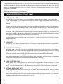
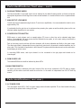
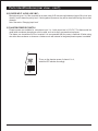
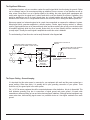
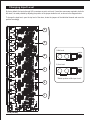
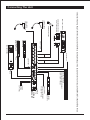
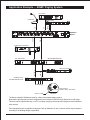
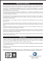
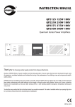
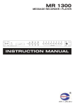
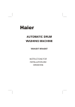
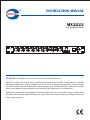
INSTRUCTION MANUAL
MX2222
Pre Amplifier Mixer
CH1
CH2
CH3
CH4
CH5
CH6
SOURCE
EXT INPUT
TONE CTRL
OFF
MASTER
MX 2222
SELECT
TUNER
OFF
MIN
MIN
SIG IN
MAX
MIN
SIG IN
MAX
MIN
SIG IN
MAX
MIN
SIG IN
MAX
MIN
SIG IN
MAX
MIN
SIG IN
MAX
MIN
SIG IN
MAX
MAX
CHIME
MIN
MAX
MIXER
TREBLE
BASS
MIN
POWER
I
CASS
CD
AUX
O
amperes
MAX
SIG IN
MUSIC SOURCE
Thank you for selecting and trusting another product from Amperes Electronics.
MX2222 is a product born out from years of experience and untiring research in BGM / Paging applications. MX2222
may appear indifferent from other pre-amplifier mixer, but do not be mistaken with its appearance. Its small compact
size offers unbeatable features for application in general paging system or BGM broadcasting, conference room audio
mixing, lecture theater sound reinforcement system and many other applications to your imaginations.
MX2222 offers a great product with reliability, accuracy and quality which every unit is tested to stringent testing method
with state of the art testing tool. Make MX2222 a part of your delicate system and experience what Amperes has to offer
from its range of products.
VER 2 / 14
Important Safely Instructions
The lightning flash symbol with arrowhead within an equilateral
triangle is intended to alert the user to the presence of uninsulated
"dangerous voltage" within the product's enclosure, that may be
sufficient magnitude to be a risk of electric shock to person.
WARNING !
RISK OF ELECTRICAL SHOCK
DO NOT OPEN
THIS UNIT MUST BE EARTHED
The exclamation mark within an equilateral triangle is intended to alert
the user to the presence of important operating and maintenance (servicing) instructions in the literature
accompanying the appliance.
WARNING - When using electric products, basic precautions should always be followed including the followings :
1. Read all the SAFE INSTRUCTIONS before using the product.
2. This product must be earthed. If it should malfunction or breakdown, grounding provides a path of least resistance
for electric current to reduce risk of electric shock.
This product is equipped with a cord having an equipment grounding conductor and a grounding plug.
The plug must be plugged into an appropriate outlet that is properly installed and earthed in accordance with all local
codes and ordinance.
DANGER - Improper connection of the equipment-grounding connector can result in a risk of electric shock. Check
with a qualified electrician or servicemen if you are in doubt as to whether the product is properly grounded. Do not
modify the plug provided with the product, It it will not fit the outlet, have a proper outlet installed by a qualified
electrician.
3. To reduce the risk of injury , close supervision is necessary when the product is used near children.
4. Do not use this product near water, for example, near a bathtub, washbowl, kitchen sink, in a wet basement or
near a swimming pool or the like.
5. This product should be located so that its location or position does not interfere with its proper ventillation.
6. This product should be located away from heat sources such as radiators, heat registers or other products that
produce heat.
7. This product should be connected to a power supply only of the type described on the operating instructions or as
marked on the product.
8. This product may be equipped with a polarized line plug (one blade wider than the other). This is a safety feature.
If you are unable to insert the plug into the outlet, contact an electrician to replace your obsolete outlet. Do not defeat
the safety purpose of the plug.
9. The power supply cord of the product should be unplugged from the outlet when left unused for a long period of
time. When unplugging the power supply cord, do not pull on the cord, but grasp it by the plug.
10. Care should be taken so that object do not fall and liquid are not spilled into the enclosure through openings.
11. The product should be serviced by a qualified service personnel when :
a. The power supply cord or the plug has been damaged, or
b. Objects has fallen, or liquid has been spilled into the product, or
c. The product has been exposed to rain, or
d. The product does not appear to operate normally or exhibits a marked change in performance, or
e. The product has been dropped or the enclosure damaged.
12. Do not attempt to service the product beyond that described in the user-maintenance instructions. All other
serving should be referred to qualified service personnel.
13. WARNING - do not place objects on the products' power cord or place it in a position where alone could trip over,
walk on or roll anything over it. Do not allow the product to rest on or to be i nstalled over power cords of any type.
Improper installations of this type create the possibility of fire hazard and / or personal injury.
AMPERES MX2222 PRE-AMPLIFIER MIXER
PAGE 2
Although MX2222 may sound familiar to you like other mixer, we recommend a brief read out of this manual to avoid
any error in installation. A few minutes of reading is all that it takes to capture the full features this mixer has to offer. We
believe the instructions laid shall enable you to install it correctly, professionally and commission them to the full
satisfaction of your clients.
Kindly keep this manual for any future reference.
Parts Identifications (front view)
1. INPUT VOLUME KNOBS
The rotary knobs for mic / line inputs 1 to 6 are for adjustment of input signal levels before the main mixed output.
In setup, adjust this gain to the optimum level according the required output level. Different channel may have
different input source (ie. condenser mic or dynamic mic, etc ), thereby the level of different channels may be set
differently.
Adjustment of high gain may distort the original signal but too low may cause insufficient signal to the mixer output.
Thereby trim each channel individually by fixing the main output to a certain level ( 75% ) while turning off other
channels. Repeat this step and mark the level at each knob to avoid constant sound setup.
Mic channel 1 and 2 ( and external mixer and chime inputs ) would have priority over other mic input channels. This
muting can be disabled by adjusting the mute level control at the back of the unit. By disabling this function, the mixer
can be applied to wider usage such as hall of prayer, lecture theaters, etc.
By factory default, the input level had been set for mic input. To convert it into line level. Please refer to section
‘Changing Input Level’
2. SIGNAL LED
The presence of input signal is indicated at this LED. The strength of input signal shall determine the brightness of
the LED output.
3. BGM SOURCE LEVEL KNOB
This knob is used to adjust the level of music source signal which has been selected from the source selector.
Although different type of music players may have different output level, the selected source shall have a constant
output thanks to its inputs balancing circuitry. Therefore a one time BGM source setup shall be enough whenever
BGM source switching is made. Adjusting the volume shall also affect the level of BGM output terminal.
Setup for the required output level of BGM source shall be similar to setup for microphone inputs and we always
recommend a marking at the knob scale whenever the optimum level is reached.
4. CHIME INPUT LEVEL KNOB
External chime / tone or siren generator may be connected to the mixer which would have priority over other
channels. Thereby the presence of chime signal shall override or mute other inputs except external mixer, mic input
1 and 2. The level of the chime signal can be adjusted via this knob but the priority feature cannot be bypassed.
5. EXTERNAL MIXER LEVEL KNOB
External mixers are used when more input channels are required, when linking separate PA systems in different
buildings. Adjust the appropriate level using this knob by following above mentioned method of setup.
External mixer input together with Mic 1 and 2, and chime inputs have priority over other channels. This function can
be disabled by adjusting priority mute level knob. See item 19.
AMPERES MX2222 PRE-AMPLIFIER MIXER
PAGE 3
MIN
MAX
MAX
1
MIN
MAX
AMPERES MX2222 PRE-AMPLIFIER MIXER
MIN
SIG IN
MAX
MIN
SIG IN
MAX
MIN
SIG IN
MAX
SIG IN
MIN
SOURCE
3
SIG IN
CH6
MAX
MAX
CHIME
MIN
MAX
MIXER
MIN
EXT INPUT
4
MIN
CH5
TREBLE
BASS
TONE CTRL
6
SIG IN
CH4
SIG IN
MIN
MASTER
MAX
7
SIG IN
CH3
OFF
CASS
TUNER
MUSIC SOURCE
CD
SELECT
OFF
8
CH2
AUX
O
I
POWER
10
2
AC 230V 50/60HZ
MX 2222
CH1
amperes
Parts Identifications
FRONT VIEW
21
5
..
REAR VIEW
9
20
19
18
17
16
15
14
13
12
11
PAGE 4
Parts Identifications ( front view.... con’t)
6. BASS AND TREBLE KNOBS
The bass and treble of mix signal output can be adjusted to the desired hearing comfort via these level knobs.
Appropriate adjustment of these signal can reduce sound feedback to a certain level but not the complete elimination.
7. MAIN OUTPUT LEVEL KNOB
Overall output level is adjusted using this knob. To avoid over amplification, it is recommended this level be set to
approximately 75%.
It is advisable that the gain be set to minimum when powering the system as well as shutting down as this can
eliminate sudden signal burst to your system.
8. SOURCE SELECTION BUTTON
BGM source or music players such as cassette player, CD, tuner or other Aux can be selected using these
buttons. Once selected, the input source shall be directed into two paths, ie to the main mixing circuit and the
other as direct BGM source output.
Path to the mixing circuit would mix with other channels, with its level adjustable and finally to the mixer output.
The direct output path is independent from any input level control and is connected to external amplifiers, etc via
phone jack. This is suitable for application in dual channel PA systems which broadcast music source and uninterrupted paging to various zones.
In connecting BGM source, each input channel is to be connected to the right player and should not be
interchanged.
9. BGM SOURCE LED
The selected BGM source shall be indicated by these LEDs.
10. MAIN POWER SWITCH
AC input to the mixer is switched at this part. However if the unit is also connected to 24V DC back up supply,
switching off this switch would still render the unit active. ie. the switch is independent from 24V DC back up
source.
Parts Identifications ( rear view )
11. AC POWER CORD
The unit operate under 230V / 240V ac mains supply unless otherwise specified. The ac fuse located at the plug
top shall only be replaced with a rating of 5A max.
AMPERES MX2222 PRE-AMPLIFIER MIXER
PAGE 5
Parts Identifications ( rear view )
12. DC INPUT SUPPLY
MX2222 can also operate using 24V DC supply. When both AC and DC source is connected to the mixer, it shall
operate using the ac main whereas the DC supply shall only be consumed whenever the former failed.
We recommend that only a regulated 24V DC supply is used when the ac mains is disconnected. This back up
terminal power source can be obtained either from back up battery or UPS unit.
13. MIXER MAIN OUTPUT
This XLR connector delivers the mixed signal output from all the input sources, ie. BGM source, external links as
well as microphone inputs. The output signal is electronically balanced with 600 Ohm impedance and 1.25V max.
LEARN more about BALANCE / UNBALANCE SIGNAL in the following cha. pter
14. REC OUT ( PHONE JACK )
This unbalanced line signal is to be connected to recording media such as cassette tape recorder, message
recoder, etc.
15. BGM OUT ( PHONE JACK )
Selected BGM source from the front panel source selector button shall has a direct output via this jack. This can be
utilized for dual channel BGM / Paging broadcast system. Also refer to Paragraph 8.
16. CHIME INPUT JACK
External chime / tone generator is connected to this jack and shall automatically mute signals from other channels
except External Mixer and Microphone Ch 1 and 2, which share the same priority level.
17. MIXER INPUT JACK
External mixer shall be connected to this input and in the presence of the signal, it shall mute other sources.
Priority level is the highest for this channel.
18. BGM SOURCE INPUTS
BGM source such as Cassette Player, CD, Tuner and Aux are connected via RCA jack Please do not interchange
the assigned inputs as different players shall have different output levels. Wrong assignment shall cause undesired
output due to signal leakage.
19. PRIORITY MUTE LEVEL SETTING
The muting circuitry activates in the presence of signals that are presence in Ext Chime or Ext Mixer Input or Mic 1
and Mic 2. This knob adjustment determines the mixing level of mic or line input signals with the signals of priority
channels. Adjusting it to minimum shall cut off all other inputs when signal is presence in priority channels, whereas
setting it to max shall allow free mix of all signals including priority inputs.
Some application shall not require this feature, such as in the hall of prayer , thereby to bypass the circuitry, adjust
the level to the maximum.
AMPERES MX2222 PRE-AMPLIFIER MIXER
PAGE 6
Parts Identifications (rear view... con’t)
20. SOURCE INPUT JACKS (LINE / MIC)
Microphones inputs 1 to 6 are connected to the mixer using XLR connectors with balanced signal. Mic or line input
channel 1 and 2 shares the priority level. If both signals are presence, they will be mixed while muting other normal
channels.
Note: See section ‘Changing Input Level’
21. PHANTOM POWER DIP SWITCH
Phantom power are available for microphone input 1 to 4 with output level of 12V DC. This feature shall be
useful when condenser microphones are to be used, such as tie clip or gooseneck microphones.
The feature can be switched off if not required. It is recommended that the power is switched off when using
mics other than condensor or whenever a condensor mic with external or integrated phantom power is available.
To turn on the phantom power of channel 1 to 4,
switch the DIP switches accordingly.
AMPERES MX2222 PRE-AMPLIFIER MIXER
PAGE 7
Balanced and Unbalanced... the difference and effects
Some installations produce audio output which is far undesired from others, mainly due to the wrong method of cabling
or terminations. This is apparently true for installations which have cables carrying signal of sources distance apart from
the main rack or interconnecting separate racks or perhaps due to improper understanding of grounding. To understand
why noise appears in the system, we have to understand the basic theory of signal transmission, ie. Balanced and
Unbalanced signal operation.
Unbalanced Signal
Unbalanced system in found in most of home AV system which uses two conductors to carry the signal, one being
the 'hot' and the other for 'ground'.
Balanced Signal
Two twisted cable and a ground shielding conductors are used to carry signal in a balanced system. The two signal
conductors transmit the identical input signals but are out of phase with each other and the ground shielding
conductor carries no signal be would pick up noise along the way to the system. However due to the amplification
circuitry , useful signal shall be amplified twice while the noise shall be eliminated.
FEMALE
MALE
MIC/BALANCED INPUT XLR
1
2
MIXER BALANCED OUTPUT XLR
1 - GROUND / SCREEN
2 - HOT ( +VE )
3 - COLD ( - )
1
2
3
FOR UNBALANCED, CONNECT
PIN 1 AND 3 TOGETHER
3
FOR UNBALANCED, SPARE PIN 3
TIP : +VE / HOT SIGNAL
PHONE JACK
RING : -VE / COLD
SLEEVE : GROUND / SCREEN
AMPERES MX2222 PRE-AMPLIFIER MIXER
PAGE 8
The Significant Difference
In unbalanced system, only one conductor carries the useful signal while the other being the ground. Cables
run in a distance may act as an antenna picking up radiations from ac sources, or from dimmers as well as
other noises. Since there is no out of phase signals in the cabling, the noise signals shall superimpose with
useful audio signal. As the signal level is rather small which could not diminish the effects of radiations, they
would be amplified as one lot of signal, thereby hum, etc is heard together with audio signal. This could be
disastrous if the cable is run in a longer distance which criss cross with other cabling like dimmer system, etc.
Noise may appear in a balanced system but at a much lower magnitude as compared to unbalanced system.
Microphones which generates amplitude in milivolts requires a better signal carrying method, ie. balance
system. Signal produced are out of phase with each other and when reaching the op-amp, one conductor shall
be amplified positively while the other inverted. Noise which do not have polarity shall be canceled at the
op-amp output. Thereby the useful signal is amplified twice while the noise is subdued.
The understanding of how this works can be easily illustrated in the diagram bel
ow.
SUMMATION OF +VE AND -VE
SIGNALS
BALAN CED SIGNALS ARE IDENTICAL AND
OUT OF PHASE BETWEEN +VE AND -VE LINE
NOISE
BOT H NOISE AND
AUDIO SIGNALS'S
PHASE UNCHANGED
+VE
+
-
-VE
SCREEN
NOISE
AUDIO SIGNAL AMPLITUDE DOUBLED
WHEREAS NOISE IS CANCELED
OUT
OP-AMP
AUDIO AND NOISE
SIGNALS ARE
INVER TED
AT -VE INPUT
SCREEN SIGNAL IS EAR THED RESULTING
ZERO SIGNAL
The Proper Cabling - Ground Looping
It is important that the mains power is connected to your equipment with earth and the power system has a
proper earthing. When hum exists, it is possibly due to poor grounding connection of your system. There
should be only one ground point in the entire system.
Pin 1 of XLR at source equipment should be connected whereas at the destination, this pin is dismantled. This
shall eliminate grounding loop due to connections of signal ground and power ground. A looped cable
resembles an antenna picking up hum and other electromagnetic radiations. Although earthed equipment may
cause mains hum, disconnecting signal screen is a preferred choice as it has higher resistance than earth
ground.
AMPERES MX2222 PRE-AMPLIFIER MIXER
PAGE 9
Changing Input Level
By factory default, the inputs through XLR connectors are set to mic level. If more line sources are required to be fed to
the mixer, it is made possible by adjusting the position of the jumper inside the unit, as shown in the diagram below.
To change the input level, open the top level of the mixer, locate the jumpers of the individual channel and move the
position accordingly
6
5
1) Mic Level
marker
4
2) Line Level
3
marker
* Default position as Mic Input Level
2
1
PCB (REAR)
AMPERES MX2222 PRE-AMPLIFIER MIXER
PAGE 10
AMPERES MX2222 PRE-AMPLIFIER MIXER
AC 230V 50/60HZ
MIN
SIG IN
MAX
MIN
SIG IN
MAX
MIN
SIG IN
CH3
MAX
MIN
SIG IN
CH4
MAX
SIREN
POWER
BALANCE OUTPUT
MIN
SIG IN
CH5
MAX
MIN
SIG IN
CH6
MAX
SIG IN
MIN
SOURCE
MAX
MAX
CHIME
MIN
MAX
MIXER
MIN
EXT INPUT
TREBLE
BASS
TONE CTRL
SIG IN
MIN
MASTER
MAX
OFF
CD
CASS
SELECT
MUSIC SOURCE
TUNER
OFF
AUX
O
I
POWER
amperes
EXTERNAL MIXER LINK FOR
CHANNEL NUMBER EXPANSION OR
FROM REMOTE SYSTEM
CHIME
RECORD LINE OUT
PA 2480
REC
OUT
SIGNAL -40 dB
SIGNAL -10 dB
CLIP
PROTECT
POWER
MP 1020
OFF/ON
/ V-
FM
/ V+
MODE
AUX LINE INPUT
UNBALANCED
PUBLIC ADDRESS POWER AMPLIFIER
STATUS
CH 1
MAX
MIN
MAX
OFF/ON
/ V-
/ V+
FM
MODE
MEDIA PLAYER
CH 2
set DIP sw 2 to ON
MIN
DUAL CHANNEL DIGITAL MEDIA PLAYER
EXIT
BACK
MESSAGE RECORDER
amperes
CD / DVD / VCD PLAYER
WIRELESS TIE CLIP OR
WIRELESS HANDHELD MIC
HANDHELD WIRED MIC
GOOSENECK MIC
(PHANTOM PWR)
DESKTOP PAGING
MICROPHONE
Above diagram shows typical equipments that can be connected to the mixer. Channel allocation for equipments shall not necessary follow the above illustration.
MX 2222
CH2
CM 1400
..
CH1
CHIME / SIREN
GENERATOR
TO PA AMPLIFIER FOR
UNINTERRUPTED PAGING
SYSTEM SETUP
TO AC M
230/240V ac
AMPERES
MX2222
FROM 24v DC
BACK UP
BATTERY
MONO
POWER AMPLIFIER
Connecting The Unit
PAGE 11
Application Example .... BGM / Paging System
CD PLAYER
PAGING MIC
MEDIA PLAYER
CH2
CH3
CH4
CH5
CH6
SOURCE
/ V-
/ V+
CH 1
MODE
EXT INPUT
TONE CTRL
OFF
MASTER
MX 2222
MAX
MIN
MAX
MIN
SIG IN
MAX
MIN
MAX
SIG IN
MIN
MAX
SIG IN
MIN
MAX
SIG IN
MIN
MAX
FM
OFF/ON
MAX
/ V-
/ V+
MODE
POWER
I
CASS
TREBLE
BASS
MIN
AMPERES
MX2222
amperes
O
AUX
CD
MAX
MIXER
SIG IN
L I NE OUT
SIG IN
MIN
MIN
MAX
MUSIC SOURCE
SIG IN
BGM OUT
MIN
SIG IN
MAX
CHIME
MAX
SELECT
TUNER
OFF
MIN
CH 2
MIN
CASS
TUNER
CD
C H1
OFF/ON
CH1
DUAL CHANNEL DIGITAL MEDIA PLAYER
FM
MP 1020
EM ERGENCY PAGING MIC
FIRE
AM P FOR PAGING
AMP FOR BGM BROADCAST
POWER
PA 2480
amperes
PROTECT
POWER
PA 2480
amperes
PROTECT
CLIP
CLIP
SIGNAL -10 dB
SIGNAL -10 dB
SIGNAL -40 dB
SIGNAL -40 dB
PUBLIC ADDRESS POWER AMPLIFIER
PUBLIC ADDRESS POWER AMPLIFIER
2
5
4
4
MAX
6
MONITOR VOLUME
1
7
8
3
2
3
4
5
7
6
8
9
AMPLIFIER OUTPUT SIGNAL
10
amperes
9
2
AMPLIFIER MONITOR
10
1
12
11
AMPLIFIER SELECT
-10
-5
0
3
6
AMPLIFIER OUTPUT LEVEL METER ( dB )
BGM I N
PAGI NG I N
AMPLIFIER MONITOR
3
1
OFF
AM 4120
AMPERES ZS5602
SPEAKER ZONE SELECTOR
TO SPEAKERS
MIN
CD
MAX
CH.1 / 2 / EXT.IN
PRIORITY MUTE
ZOOM VIEW OF
PRIORITY MUTE LEVEL KNOB
ADJUST TO MIN
The above schematic illustrates a setup for a basic uninterrupted paging system.
Note that the priority mute level knob is adjusted to the maximum to allow the mute feature to be fully active.
This level can be adjusted mid way or so if it is to allow a paging to be made with background music audible at
lower volume.
Other equipments such as amplifier changeover, back up batteries, etc are not shown, which may be required
according to the building design requirements.
AMPERES MX2222 PRE-AMPLIFIER MIXER
PAGE 12
Application Example... Lecture Hall / Conference Room
MESSAGE RECODER
BACK
EXIT
STATUS
MEDIA PLAYER
WIRELESS CLIP
MICROPHONE
DUAL CHANNEL DIGITAL MEDIA PLAYER
CH 1
FM
MP 1020
OFF/ON
/ V-
/ V+
CH 2
MODE
MIN
MAX
MIN
FM
OFF/ON
MAX
/ V-
/ V+
MODE
CD PLAYER
HANDHE LD MIC
CH1
CH2
CH3
CH4
CH5
CH6
SOURCE
AUX
CD
CASS
REC OUT
CH2
CH1
COMPUTER AUDIO INPUT
EXT INPUT
TONE CTRL
OFF
MASTER
MX 2222
SELECT
TUNER
OFF
MIN
MIN
MAX
MIN
SIG IN
MAX
MIN
SIG IN
MAX
MIN
SIG IN
MAX
MIN
SIG IN
MAX
MIN
SIG IN
MAX
MIN
MAX
CHIME
MIN
POWER
I
CASS
CD
O
AUX
MAX
MIXER
SIG IN
TREBLE
BASS
MIN
SIG IN
amperes
MAX
AMPERES
MX2222
MUSIC SOURCE
LINE OUT
SIG IN
MAX
POWER
PA 2480
amperes
PROTECT
CLIP
SIGNAL -10 dB
POWER AM P
SIGNAL -40 dB
PUBLIC ADDRESS POWER AMPLIFIER
FULL RANGE
SPEAKER S
MIN
CD
MAX
CH.1 / 2 / EXT.IN
PRIORITY MUTE
ZOOM VIEW OF
PRIORITY MUTE LEVEL KNOB
ADJUST TO MIN
The above schematic shows a simple setup for sound reinforcement in lecture theater or for sound
reinforcement in lecture theater or conference room or hall of prayer.
Note that the priority mute level is set to minimum, thus allow free mix of signal from all channels.
AMPERES MX2222 PRE-AMPLIFIER MIXER
PAGE 13
Technical Specifications
Operating voltage
230 / 240V ac or 24V DC
Power consumption
2.4W on 240V ac / 100 mA on 24V DC
Input channels
6 x mic ; 4 x BGM ; ext chime in ; mixer link
Input impedance
Mic : 600 Ohm
BGM : 47 K Ohm unbalanced
Chime input : 10 K Ohm unbalanced
Mixer link : 600 Ohm balanced
Differential Input Resistance
Sensitivity(1.2 mVrms output)
175 Ohm for all Mic / Line input
Line : 530 mVrms
Mic : 2.5 mVrms
Output level
1.2V XLR balanced (mixed output)
1.0V phone jack balanced (BGM output)
Output impedance
600 Ohm balanced
Controls
Mic channel ; chime ; mixer input
Master mixed ; BGM ;
Bass and treble controls
Phantom power
12V DC switchable at mic 1 to 4
Frequency response
175 - 15 KHz (+/- 3 dB at 1 KHz) with low cut
S/N ratio
> 60 dB at 1 KHz
Dimensions (WxHxD)
Weight
482 x 44 x 180 mm
2.5 kg
The above specifications may change without prior notice subject to our product
improvement policy
AMPERES MX2222 PRE-AMPLIFIER MIXER
PAGE 14
CE Declaration of Conformity
Declaration Of Conformity
for CE Mark
Amperes Electronics Sdn Bhd
Manufacturer’s Name:
Manufacturer’s Address:
Amperes Electronics Sdn Bhd
No 70, Jln Industri PBP3, Taman Perindustrian Pusat Bandar Puchong,
47100 Puchong, Selangor, Malaysia.
Product Name:
Model Number:
Pre - Amplifier Mixer
MX2222
Conforms to the following standards:
EN 55013: 2001+A1:2003+A2:2006
EN 61000-3-2: 2006+A1:2009+A2:2009, EN 61000-3-3: 2008
EN 55020: 2007+A11:2011
EN 61000-4-2: 2009, EN 61000-4-3: 2006+A1:2008+A2:2010
EN 61000-4-4: 2012, EN 61000-4-5: 2006
EN 61000-4-6: 2009, EN 61000-4-8: 2010, EN 61000-4-11:2004
EN 60065: 2002+A1:2006+A11: 2008+A2:2010+A12:2011
We hereby declare, that the above product conforms to LVD directive 2006/95/EC for safety of Electrical apparatus
and EMC directive 2004/108/CE for Electromagnetic Compability and bears the CE marking accordingly.
Oct 18, 2013
Kuala Lumpur, Malaysia
Name / Signature
Managing Director
AMPERES MX2222 PRE-AMPLIFIER MIXER
PAGE 15
Warranty Conditions
Only Amperes Electronics Service Centres are allowed to make warranty repairs : a list of Amperes Electronics
Service Centres may be asked for by the purchaser or send directly to Amperes Electronics Sdn Bhd at 70 Jalan
Industri PBP 3, Tmn Perindustrian Pusat Bandar Puchong, 47100, Puchong, Selangor, Malaysia or its authorized
master distributor, TNT Links Sdn Bhd / MyPA Systems Sdn Bhd. This warranty is not valid if repairs are performed
by unauthorized personnel or service centres.
This warranty covers only repairs and replacement of defective parts ; cost and risks of transportation as well as
removal and installation of the product from the main system are for the account of the purchaser. This warranty shall
not extend to the replacement of the unit.
This warranty does not cover damages caused by misuse, neglect, accident of the product as well as using the
product with power supply voltage other than shown on the product, or any other power supply source / adaptor not
recommended by the manufacturer.
This warranty does not cover damages caused by fire, earthquakes, floods, lightning and every cause not directly
related to the unit.
This warranty does not include any indemnity in favor of the purchaser or the dealer for the period out of use of the
unit; moreover the warranty does not cover any damages which may be caused to people and things when using the
product.
This warranty certificate is valid only for the described product, and is not valid if modifications are made on this
certificate or on the identification label applied on the product.
This warranty covers all the material and manufacturing defects and is valid for a period of 12 months from the date of
purchase or for a longer period in countries where this is stated by a national law. In this case, the extension is valid
only in the country where the product is purchased.
Amperes Electronics Sdn Bhd is not obliged to modify previously manufactured products under warranty if the design
changes or improvements are made.
Disclaimer
Information contained in this manual is subject to change without prior notice and does not represent a commitment
on the part of the vendor. AMPERES ELECTRONICS SDN BHD shall not be liable for any loss or damages
whatsoever arising from the use of information or any error contained in this manual.
It is recommended that all services and repairs on this product be carried out by AMPERES ELECTRONICS SDN BHD
or its authorized service agents.
AMPERES series must only be used for the purpose they were intended by the manufacturer and in conjunction with
this operating manual.
AMPERES ELECTRONICS SDN BHD cannot accept any liability whatsoever for any loss or damages caused by
service, maintenance or repair by unauthorized personnel, or by use other than that intended by the manufacturer.
ISO 9001: 2008
Design & Manufacture of Public Address Equipment and Systems
Certificate No. 16895 / A / 0001 / UK / En
AMPERES ELECTRONICS SDN BHD
MADE IN MALAYSIA
Published : March 2014