1
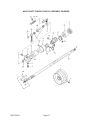
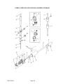
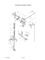
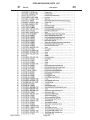
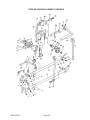
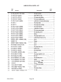
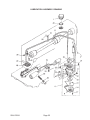
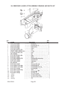
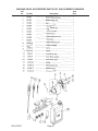
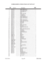
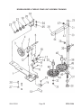
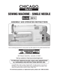
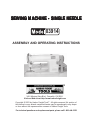
SEWING MACHINE - SINGLE NEEDLE
03914
ASSEMBLY AND OPERATING INSTRUCTIONS
3491 Mission Oaks Blvd., Camarillo, CA 93011
Visit our Web site at http://www.harborfreight.com
Copyright © 2003 by Harbor Freight Tools®. All rights reserved. No portion of
this manual or any artwork contained herein may be reproduced in any shape
or form without the express written consent of Harbor Freight Tools.
For technical questions and replacement parts, please call 1-800-444-3353
Specifications
ITEM
DESCRIPTION
Machine Type
Heavy duty, industrial sewing machine; high
speed, single needle-lock stitch
Drive
V-belt driven
Action
Foot pedal operation, along with a knee and
manual lifting arm for presser foot. Presser
tension adjustment
Sewing Thickness
5/16 inch maximum
Feed Type
Link style needle feed reduces slippage
Sewing Directions
Forward and reverse feed
Stitching Speed
5500 Stitches per minute
Motor Type
Clutch motor; 3450 RPM, 5.8 amps, 110/220V,
110 VAC at
60 Hz; single phase
Overall weight
61.6 lbs
Machine Dimensions
20-3/4 (L) x 10 (H) inches
Accessories
-
Table Stand Kit
Table Stand Kit (Model 03929) not included
Screwdrivers
3 Bobbins
Small lubricating bottle with tip
10 pack of needles
Power Switch
Caution: Make certain that the voltage switch on the motor is set correctly
for your use. See page 6.
This Machine requires oil to be added before use -see page 6 for details.
Save This Manual
You will need the manual for the safety warnings and precautions, assembly instructions,
operating and maintenance procedures, parts list and diagram. Keep your invoice with this
manual. Write the invoice number on the inside of the front cover. Keep the manual and
invoice in a safe and dry place for future reference.
Safety Warnings and Precautions
WARNING: When using tool, basic safety precautions should always be followed to reduce the risk of personal injury and damage to equipment.
Read all instructions before using this tool!
1.
Keep work area clean. Cluttered areas invite injuries.
2.
Observe work area conditions. Do not use machines or power tools in damp or wet
locations. Don’t expose to rain. Keep work area well lighted. Do not use electrically
powered tools in the presence of flammable gases or liquids.
3.
Keep children away. Children must never be allowed in the work area. Do not let
them handle machines, tools, or extension cords.
4.
Store idle equipment. When not in use, tools must be stored in a dry location to
inhibit rust. Always lock up tools and keep out of reach of children.
SKU 03914
Page 2
Rev 04/03
REV 05/03
REV 03/04
5.
Use the right product for the job. Do not attempt to force a small product or
attachment to do the work of a larger industrial tool. There are certain applications for
which this product was designed. It will do the job better and more safely at the rate
for which it was intended. Do not modify this product and do not use this product for a
purpose for which it was not intended.
6.
Dress properly. Do not wear loose clothing or jewelry as they can be caught in
moving parts. Protective, electrically non-conductive clothes and non-skid footwear
are recommended when working. Wear restrictive hair covering to contain long hair.
7.
Do not overreach. Keep proper footing and balance at all times. Do not reach over
or across running machines.
8.
Maintain tools with care. Keep tools sharp and clean for better and safer
performance. Follow instructions for lubricating and changing accessories. Inspect
tool cords periodically and, if damaged, have them repaired by an authorized
technician. The handles must be kept clean, dry, and free from oil and grease at all
times.
9.
Disconnect power. Unplug product when not in use.
10.
Remove adjusting keys and wrenches. Check that keys and adjusting wrenches
are removed from the machine work surface before plugging it in.
11.
Avoid unintentional starting. Be sure the switch is in the Off position when not in
use and before plugging in.
12.
Stay alert. Watch what you are doing, use common sense. Do not operate when you
are tired.
13.
Check for damaged parts. Before using any product, any part that appears
damaged should be carefully checked to determine that it will operate properly and
perform its intended function. Check for alignment and binding of moving parts; any
broken parts or mounting fixtures; and any other condition that may affect proper
operation. Any part that is damaged should be properly repaired or replaced by a
qualified technician. Do not use if any switch does not turn On and Off properly.
14.
Guard against electric shock. Prevent body contact with grounded surfaces such
as pipes, radiators, ranges, and refrigerator enclosures.
15.
Replacement parts and accessories. When servicing, use only identical
replacement parts. Use of any other parts will void the warranty. Only use accessories
intended for use with this tool. Approved accessories are available from Harbor
Freight Tools.
16.
Do not operate tool if under the influence of alcohol or drugs. Read warning
labels if taking prescription medicine to determine if your judgment or reflexes are
impaired while taking drugs. If there is any doubt, do not operate the tool.
SKU 03914
Page 3
17.
Use proper size and type extension cord. If an extension cord is required, it must be
of the proper size and type to supply the correct current to the tool without heating up.
Otherwise, the extension cord could melt and catch fire, or cause electrical damage to
the tool. This tool requires use of an extension cord with up to 10 amps capability (up
to 50 feet), with wire size rated at 18 AWG. Longer extension cords require larger size
wire. If you are using the tool outdoors, use an extension cord rated for outdoor use.
(signified by “WA” on the jacket).
20.
Maintenance. For your safety, service and maintenance should be performed
regularly by a qualified technician.
21.
Pacemaker safety warning. People with pacemakers should consult with their
physician(s) before using this product; operation of equipment in close proximity to a
heart pacemaker could cause interference or failure of the pacemaker.
Note: Performance of this tool may vary depending on variations in local line voltage. Extension cord usage may also affect tool performance.
Warning: The warnings, cautions, and instructions discussed in this instruction manual
cannot cover all possible conditions and situations that may occur. It must be understood by the operator that common sense and caution are factors which cannot be
built into this product, but must be supplied by the operator.
Sewing Safety Precautions
1.
Keep hands away from the needle when you turn the power switch on, or while the
machine is operating.
2.
Do not place your fingers into the thread take-up cover while the machine is
operating.
3.
Always turn the machine off and unplug the power cord to the electrical outlet before
tilting the machine head or removing the V-belt.
4.
Never leave the machine running and unattended.
5.
During operation, never place your head, hair, or hands in the proximity of the hand
wheel, V-belt, bobbin winder, or motor.
6.
Do not operate the machine with any safety guards removed.
Unpacking
When unpacking, check to make sure that the parts shown in the photo on the following
page are included. Note that the machine table shown is not included, and must be ordered
separately. If any parts are missing or broken, please call Harbor Freight Tools at the number on the cover of this manual as soon as possible.
SKU 03914
Page 4
Sewing Machine
Table Stand and
Top (not provided)
Power Switch
Motor
Knee Lifting Arm
for Presser Foot
Assembly
The assembly instructions describe mounting the Single-Needle Sewing Machine (Model
03914) to the Table Stand (Model 03929), not included. In order to complete this procedure,
you must first purchase and assemble the Table Stand Kit (Model 03929).
1.
Locate four corner rests in the rectangular hole of the Table Stand where the machine
will sit.
2.
Place two rubber seats (A) on the operator-side, corner rests and secure with
supplied hardware (C). See figure 1.
3.
Place two cushion seats (B) on the hinge-side, corner rests and secure with supplied
hardware (C).
4.
Seat the Oil Pan (D) on the corner seats (A) and (B). See figure 2.
5.
Insert Hinges (E) into the opening in the machine bed. See figure 3.
SKU 03914
Page 5
6.
Fit the machine head to the table rubber hinges (F) before placing the machine head
on the corner seats. See figure 4.
7.
Tilt the machine back to expose the Oil Pan (D). See figure 5.
8.
Fill the Oil Pan with sewing machine lubrication oil (#7 white oil) to the “high” mark “A”.
Add more oil when the level is to the “low” mark “B”. After lubrication, and during
operation, oil splashing can be seen through the Oil Sight Window (H).
9.
Lower the machine head to the table top.
10.
Mount the Motor to the underside of the table top as shown below. Use the supplied
hardware.
Note: Top switch is for
rotation. Switch left for
counterclockwise;
switch right for clockwise
rotation.
Note: Motor is 110/220V
Single Phase. Flip switch
to desired voltage (no
re-wiring needed). Switch
left for 110V, switch right
for 220V.
(K)
Note: Receptacle for 6 volt work
light (not included).
11.
Place the V-belt around the Sewing Machine Pulley, through the slot in the table top,
and around the Motor pulley. Attach the Pulley Safety Cover.
12.
Tighten the V-belt tension by adjusting the long bolt and nut at location (K). The
proper tension is reached when the V-belt can only be pushed in 1/2 inch.
SKU 03914
Page 6
REV 04/03
REV 05/03
13.
Mount the Power Switch under the table top, on the operator’s side. Use the supplied
hardware.
Power Switch
Mounting the Thread Stand
Note: The Thread Stand is designed to be mounted on the Table Stand Kit
(Model 03929-not included). Unless indicated otherwise, all parts referred
to in this set of instructions are listed in the Bobbin Winder & Thread Stand
Unit Parts List found on page 28. During assembly, it will be helpful to
refer to that list and the diagram that follows it on page 29.
14.
Locate the large hole in the far right corner (from the location that the operator will be
seated) of the Table (not included). Place the Rubber Washer (45) and Washer (37) onto
the Lower Spool Rest Rod (36) and insert the Rod into the hole mentioned above. Place
another Washer (37) over the end of the Rod, and thread on and tighten a Nut (38).
15.
Place the Spool Support (46) over the Lower Spool Rest Rod (36) about halfway down.
Insert a Screw (31) and Nut (47) through the Support.
Note: The Support has tabs that hold onto the corners of the Nut to make tightening
easier. When assembling, place the Nut on the side with these tabs.
Tighten the Screw.
16.
Insert the threaded end of the Spool Pin (40) through one of the holes in the top of the
arm of the Spool Support (46). Place a Washer (32) and Nut (35) over the end of the Pin
and tighten. Place the Spool Rest (41), Spool Mat (42), and the Spool Vibration Stopper
(39) over the end of the Spool Pin. Repeat this step for both of the Spool Pins (40).
17.
Place the Column Pipe Connector (33) over the top of the Lower Spool Rest Rod (36)
until the Rod is about halfway through the Connector. Place a Screw (34) and Nut (35)
through the bottom hole in the Connector and finger-tighten.
18.
Place the Upper Spool Rest Rod (30) into the top of the Column Pipe Connector (33).
Place a Screw (34) and Nut (35) through the top hole in the Connector. Tighten all of the
Screws and Nuts in the Connector.
19.
Place the Thread Hanger (28) about halfway over the top of the Upper Spool Rest Rod
(30). Insert a Screw (31) and Nut (47) through the Hanger as explained in the note in
step 14, above. Tighten the Screw and place the Column Cap (29) over the end of the
Upper Spool Rest Rod (30).
SKU 03914
Page 7
REV 03/04
Mounting the Bobbin Winder
Note: Unless indicated otherwise, all par ts
referred to in this set of instructions are listed
in the Bobbin Winder & Thread Stand Unit
Parts List found on page 28. During
assembly, it will be helpful to refer to that list
and the diagram that follows it on page 29.
20.
Remove the Belt Cover (part 4, on page 27). Swing the
sewing machine so the base is in the operating position,
resting on the table. Set the Bobbin Winder to the ‘ON’
Position-see ON Position, below.
21.
Make sure the Bobbin Winder is in the ‘ON’ position.
Position the Base (Bobbin Winder Base Assembly) (1) so
that the Thread Winder Assembly (3) lines up with and just
touches the belt. Mark pilot hole locations on the table at
the far end of each of the two channels in the Base as
indicated in Figure A.
Figure A
Mark
Pilot
Holes
Here.
Figure B
22.
Set the Base (1) aside and swing the sewing machine out
of the way. Carefully drill straight pilot holes for each of the
two locations marked above. Place the base in location
and secure using two Wood Screws (26) and Washers (27).
Leave the Screws just loose enough to allow the Base to slide.
23.
Swing the Sewing Machine back into it’s operating position. Put the Bobbin Winder in
the ‘OFF’ position-see OFF Position, below.. Slide the Bobbin Winder Assembly close
to the belt until it just barely doesn’t touch it (1/8” gap or less)-see Figure B, above. Tighten
the Wood Screws (26) from step 22, above.
24.
Put the Belt Cover back on the Sewing Machine before use.
Operation
Caution: To properly break-in your new sewing machine, and
avoid possible damage to the machine, sew at moderate to slow
speeds for the first 15 minutes of use.
6
Bobbin Winder Operation
The Bobbin Winder not only assists in winding thread onto the
Bobbin, but it also makes the belt tight, operating the rest of the
machine. The Bobbin Winder has two positions, ‘ON’ and ‘OFF’:
OFF Position The Bobbin Winder won’t contact the belt, causing
the machine to ‘idle’.
WARNING: While the machine is ‘idling’ the needle or
other parts can possibly still move at any time. Shut the
machine off completely before working around the needle
or other moving parts.
SKU 03914
Page 8
ON
Position
6
OFF
Position
REV 03/04
ON Position
This position is with the Connecting Rod
(6) pressed, as shown in Figure C. The Bobbin
Winder will put pressure on the belt and cause the
machine to operate. The Shaft on the Bobbin Winder
will also spin; winding thread onto the Bobbin, if the
Winder is set up to do so.
Figure C
6
Winding Thread Onto the Bobbin
1.
Place a Bobbin onto the Bobbin Winder Shaft (5) as
shown at point d in Figure C, right.
2.
Route the Thread from the Spool (not shown) up through
the Thread Guide Tube (43, point a), the hole in the
Thread Tension Bracket Assembly (18, b), over and
under the far side of the Tension Disc (21, c), and connect
it to the Bobbin (d).-See Figure D, right.
3.
While the Connecting Rod (6) is pressed (as shown in
both Figures C and D) the Bobbin Winder will be in the
‘ON’ position and the Bobbin will fill with thread. When
finished, release the Connecting Rod and the Bobbin
Winder will reset to the ‘OFF’ position.
d
b
a
Figure D
6
d
b
c
Attaching the Needle
1.
Unplug the Power Cord from the electrical outlet.
2.
Select a proper needle size according to the
thread count and type of material being sewn.
3.
Turn the Hand Wheel until the needle bar
reaches the highest point of its stroke.
4.
Loosen Screw (2) and hold needle (1) with its
indented part “A” facing exactly to the right in
direction “B”.
5.
Insert the needle and push it up until it will go no further.
6.
While holding in place, securely tighten Screw (2).
Setting the Bobbin into the Bobbin Case
1.
Hold the Bobbin so that the thread exit is to the left,
and push the Bobbin into its case.
2.
Feed the thread through slit “A” and pull the thread in
direction “B”. By doing so, the thread will pass under
the tension spring and exit at notch “B”.
3.
Verify that the Bobbin rotates in the direction of the
arrow when thread “C” is pulled.
SKU 03914
Page 9
REV 03/04
Threading the Machine Head
Set the thread spool on its holder and guide the thread through the machine as illustrated
below. The numbers in the illustration indicate the threading sequence.
Adjusting the Stitch Length
1.
To increase the stitch length, turn the Stitch Length
Dial (1) to the desired number (in millimeters) as
indicated under the scale dot (A) on the machine.
2.
To decrease the stitch length, turn the Stitch Length
Dial (1), while pressing the Feed Lever (2).
Adjusting the Needle Thread Tension
1.
Turn Tension Adjustment Knob (1) clockwise (A) to
increase thread tension.
2.
Turn Tension Adjustment Knob (1)
counterclockwise (B) to decrease thread tension.
Adjusting the Bobbin Thread Tension
1.
Turn the Tension Adjustment Screw (2) clockwise
(A) to increase bobbin tension.
2.
Turn the Tension Adjustment screw (2)
counterclockwise (B) to decrease bobbin tension.
SKU 03914
Page 10
Changing the Thread Take-up Spring Stroke and Pressure
1.
Loosen Set Screw (2).
2.
To increase the stroke, turn the Tension
Knob Screw (3) clockwise (A).
3.
To decrease the stroke, turn the Tension
Knob Screw (3) counterclockwise (B).
4.
Loosen Set Screw (2) and pull out the
Tension Arm (5).
5.
Loosen Set Screw (4) and remove the
Tension Knob Screw (3).
6.
Turn the Tension Knob Screw (3) clockwise (A) to increase pressure; or turn
counterclockwise (B) to decrease pressure.
7.
Replace Tension Knob Screw (3), tighten Set Screw (4), and replace the assembly.
Setting the Hand Lifter
1.
To stop the machine with its Presser Foot up,
turn the Hand Lifter (1) up (A).
The Presser Foot will go up about 1/4 inch and
stop.
2.
To set the Presser Foot to its original position,
turn the Hand Lifter (1) down (B).
Using the Knee Lifter, you can get the standard Presser Foot lift of about 1/2 inch.
Setting the Presser Foot Pressure
1.
Loosen Nut (2), and turn the Presser Spring
Regulator (1) clockwise (A) to increase Presser
Foot pressure.
2.
To decrease Presser Foot pressure, turn the
Presser Spring Regulator (1) counterclockwise.
3.
After adjustment, tighten Nut (2).
Adjusting the Feed Timing
1.
Loosen Set Screws (2) and (3) on the Feed
Eccentric Cam (1) and properly position the
Eccentric Cam. Retighten the Set Screws.
2.
To advance the feed timing in order to prevent
uneven material feed, move the Feed Eccentric
Cam up (clockwise).
SKU 03914
Page 11
3.
To delay the feed timing in order to increase stitch tightness, move the Feed Eccentric
Cam down (counterclockwise).
Adjusting the Height of the Feed Dog
The Feed Dog is factory adjusted so that it juts
out from the Throat Plate surface 0.8 mm to 0.9
mm. If the Feed Dog juts out too much, puckering may result when sewing lightweight materials. To adjust the height of the Feed Dog:
1.
Loosen Screw (2) of Crank (1).
2.
Move the Feed Bar up or down to make
the adjustment.
3.
Tighten Screw (2), being careful not to
overtighten.
Adjusting Needle-to-hook Timing
1.
Turn the Hand Wheel to bring the needle
bar down to the lowest point of its stroke.
2.
Loosen Set Screw (1).
3.
When using a DBX1 needle, align to
marker line “A” on the needle bar (2) with
the bottom end of the needle bar lower
bushing (3), then tighten Set Screw (1).
When using a DAX1 needle, align to
marker line “B” on the needle bar (2) with
the bottom end of the needle bar lower
bushing (3), then tighten Set Screw (1).
4.
When using a DBX1 needle, loosen three
Hook Set Screws, turn the Hand Wheel,
and align the marker line “B” on the needle
bar (2) with the bottom end of the needle
bar lower bushing (3).
When using a DAX1 needle, align the marker line “D” on the needle bar (2) with the
bottom end of the needle bar lower bushing (3).
5.
After making the adjustments in steps 3 and 4, align the Hook Blade point (5) with the
center of the needle (4).
Provide a clearance of .001” to .004” (0.04 to 0.1 mm) between the needle and the
hook. This clearance is less than 1/64” (almost touching). Securely tighten the three
Set Screws. If the clearance is too small, the tip of the hook will be abraded. If it is too
large, it will lead to skip over.
SKU 03914
Page 12
Adjusting the Presser Bar Height
1.
Loosen Set Screw (1) and manually adjust the Presser Bar
height, and the angle of the Presser Foot.
2.
After adjusting, securely tighten the Set Screw (1).
Adjusting the Thread Take-up Stroke
1.
When sewing heavy weight materials,
move the Thread Guide (1) to the left (A) to
increase the length of thread pulled out by
the Thread Take-up.
2.
When sewing lightweight materials, move
the Thread Guide (1) to the right (B) to
decrease the length of thread pulled out by
the Thread Take-up.
3.
The normal setting is when the marker line
“C” on the Thread Guide (1) is aligned with
the center of the screw.
Adjusting the Height of the Knee Lifter
The standard height of the Presser Foot lifted using the Knee Lifter is 0.39 inch (10 mm).
1.
To adjust the Presser Foot lift up to 0.5 inch (13 mm), adjust the Screw (1).
2.
When the Presser Foot lift is adjusted over 0.39 inch (10 mm), be sure that the bottom
end of the Needle Bar (2) does not hit the Presser Foot (3).
This can be manually checked by turning the Hand Wheel.
Maintenance
1.
Machine adjustments should only be performed by a qualified technician.
2.
Check the oil level weekly when the machine is used daily. Add sewing machine oil as
required to the high level marking.
3.
Clean the machine with a clean, damp cloth. Do not use solvents or thinners.
4.
When not in use, cover the machine and store in a clean and dry location.
SKU 03914
Page 13
ARM BED PARTS LIST
Ref.
No.
Part No.
SKU 03914
Description
Page 14
Amt.
Req.
ARM BED ASSEMBLY DRAWING
NOTE: When ordering parts from the following lists, always include the
list title, item number and description, and page number. For example,
to order the first part from page 14 list, you would state:
- Arm Bed Parts List
- Item #1 - Arm Bed Assembly
- Page: 14
NOTE: Some parts are listed and shown for illustration purposes only and are not available
individually as replacement parts.
PLEASE READ THE FOLLOWING CAREFULLY
THE MANUFACTURER AND/OR DISTRIBUTOR HAS PROVIDED THE PARTS DIAGRAM IN THIS
MANUAL AS A REFERENCE TOOL ONLY. NEITHER THE MANUFACTURER NOR DISTRIBUTOR MAKES ANY REPRESENTATION OR WARRANTY OF ANY KIND TO THE BUYER THAT HE
OR SHE IS QUALIFIED TO MAKE ANY REPAIRS TO THE PRODUCT OR THAT HE OR SHE IS
QUALIFIED TO REPLACE ANY PARTS OF THE PRODUCT. IN FACT, THE MANUFACTURER
AND/OR DISTRIBUTOR EXPRESSLY STATES THAT ALL REPAIRS AND PARTS REPLACEMENTS
SHOULD BE UNDERTAKEN BY CERTIFIED AND LICENSED TECHNICIANS AND NOT BY THE
BUYER. THE BUYER ASSUMES ALL RISK AND LIABILITY ARISING OUT OF HIS OR HER
REPAIRS TO THE ORIGINAL PRODUCT OR REPLACEMENT PARTS THERETO, OR ARISING
OUT OF HIS OR HER INSTALLATION OF REPLACEMENT PARTS THERETO.
SKU 03914
Page 15
MAIN SHAFT THREAD TAKE-UP PARTS LIST
Ref.
No.
SKU 03914
Part No.
Description
Page 16
Amt.
Req.
MAIN SHAFT THREAD TAKE-UP ASSEMBLY DRAWING
SKU 03914
Page 17
FABRIC--PIERCING HOOK DRIVING PARTS LIST
Ref.
No.
SKU 03914
Part No.
Description
Page 18
Amt.
Req.
FABRIC--PIERCING HOOK DRIVING ASSEMBLY DRAWING
SKU 03914
Page 19
PRESSER BAR PARTS LIST
Ref.
No.
SKU 03914
Part No.
Description
Page 20
Amt.
Req.
PRESSER BAR ASSEMBLY DRAWING
SKU 03914
Page 21
FEED MECHANISM PARTS LIST
Ref.
No.
SKU 03914
Part No.
Description
Page 22
Amt.
Req.
FEED MECHANISM ASSEMBLY DRAWING
SKU 03914
Page 23
LUBRICATION PARTS LIST
Ref.
No.
SKU 03914
Part No.
Description
Page 24
Amt.
Req.
LUBRICATION ASSEMBLY DRAWING
SKU 03914
Page 25
OIL RESERVOIR & KNEE LIFTER ASSEMBLY DRAWING AND PARTS LIST
Ref.
No.
Part No.
SKU 03914
Description
Page 26
Amt.
Req.
MACHINE HEAD ACCESSORIES PARTS LIST AND ASSEMBLY DRAWING
Ref.
No.
SKU 03914
Part No.
Description
Page 27
Amt.
Req.
BOBBIN WINDER & THREAD STAND UNIT PARTS LIST
Ref.
No.
SKU 03914
Part No.
Description
Page 28
Amt.
Req.
REV 03/04
BOBBIN WINDER & THREAD STAND UNIT ASSEMBLY DRAWING
SKU 03914
Page 29
REV 03/04