1
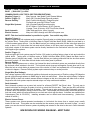
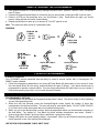
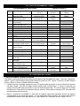
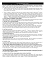
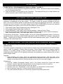
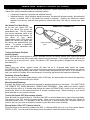
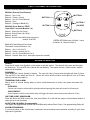
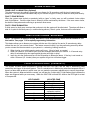
CS-2008PC
SecurLinc™
ADVANCED REMOTE CONTROL ALARM SYSTEM
INSTALLATION & OPERATING INSTRUCTIONS
*NOTE: There are several features of the CS-2008PC system that can only be accessed and/or programmed
by using optional SecurLinc™ PC software and data cable via the system’s expansion port via a Personal
Computer: An expansion kit is available which includes Software, PC linc cable and a power supply (SLA-50)
•
•
•
•
•
•
•
•
Assigning the amount of time for a “Timed” Auxiliary output channel.
Assigning Self-start temperature and voltage-drop thresholds (when using the remote start expansion
module).
“Secure Disarm” using a 4-press transmitter button sequence.
Inputs & Outputs testing and diagnostics of main system
Inputs & Outputs testing of Data Linc expansion modules i.e. Remote Start, 2-Way pager, & Aux. channel
module.
Quick & Easy option programming
Erasing transmitter codes
Adjusting Glow plug delay time, Voltage Drop Threshold
PRE-INSTALLATION CAUTIONS & WARNINGS
BEFORE BEGINNING, check all vehicle manufacturer cautions and warnings regarding electrical service (AIR
BAGS, ABS BRAKES, ENGINE COMPUTERS, BATTERY etc.).
WE RECOMMEND the use of a VOLT/OHM METER to test and verify wiring circuits. Test lights or illuminated
probes can cause damage to on-board computer or engine management systems.
DO NOT exceed maximum output ratings or damage may occur. Electrical current limits for this alarm are
listed where applicable on the system diagram (Pg. 16). If you are unsure about the current load, of a specific
circuit on your vehicle, measure the load first with an amp-meter before connecting.
WE RECOMMEND that the MAIN SYSTEM FUSE be REMOVED before jump starting, using a battery
charger, or changing the battery. A voltage surge or high boost condition could damage alarm circuits.
DO NOT ROUTE ANY WIRING THAT MAY BECOME ENTANGLED with brake, and gas pedals, steering
column, or any other moving parts in the vehicle.
TECH SUPPORT
Mon-Fri 8:00 AM-4:30 PM Pacific Time
(800) 998-6880
Website: www.crimestopper.com
Email: [email protected]
REV. A 02/2003 SW:
This device complies with FCC Rules part 15.
Operation is subject to the following two conditions: 1)
This device may not cause interference, and (2) this
device must accept any interference that may be
received, including interference that may cause
undesired operation. The manufacturer is not
responsible for any radio or TV interference caused by
TABLE OF CONTENTS
Pre-Installation Cautions & Warnings…….…………………………………………………………..………………1
Control Module & Component Mounting…………………..……………………….………………………..…….2-3
Wiring Descriptions.…………………………………………………………….……………………….……….…...3-4
System Wiring Diagrams #1 & #2……………………………………………………………….…………….…….5-6
Shock Sensor & LED / Valet POD……………………………………………………………………………………..7
Power Door Lock Wiring & Diagrams…………………….………..……………………………….………………8-9
Remote Transmitter Programming…………………………………………………………………………..………10
2-Vehicle Programming………………………………………………………………………………………..………10
Option Programming…………………………………..………….……………………………….…………….…10-13
Option Reset (Restore Defaults…………………….……………….……………………………….…………….…14
Customized Personal Override Code………………………….……………………………….……………………14
Secure Disarm Feature…………………….…………………….……………………………….……………………14
Hands-Free Transmitter (Optional)……………………………………………………………..………..………15-16
Carjack Protection Features…………………………………………………………………………………….…….16
Remote Control Diagram………………………………………………………………………………………………17
Alarm Operation……………………………………………………………………………………………….…….17-19
Remote Less Disarm “Beach Mode”…………………………………………………….…………………….…….19
Prior Intrusion Alert (Diagnostic)……….……………………………………………………………………..……..19
CONTROL MODULE MOUNTING
DO NOT Mount the control unit or wiring harness where they can become entangled with moving parts
such as brake/gas/clutch pedals, or the steering column! The alarm control module should be mounted in
a concealed location. The Placement of the module will affect the distance from which the remote transmitter
can control the unit. The antenna wire should be routed away from any metal if possible. Do not alter the
length of the antenna wire or route it with other wires. Do not ground the antenna wire. Fasten the module to
a bracket or wire harness using the cable ties provided.
Underdash Mounting: If you are locating the control unit underdash, mount it as high as possible, not easily
located by an intruder.
Driver’s Side Underdash mounting provides an easy location for wiring most of the system’s connections,
however this is a common location for an intruder to check for an alarm after breaking into the vehicle. The left
side of the vehicle may contain more metal and or wiring that will create interference and decrease the
operating range of the system.
Passenger Side underdash is a good location, however some extra wiring may be needed to extend wires
across from the driver’s side.
Under-seat / Center Console mounting is also a possibility, but NOT RECOMMENDED. The system’s
transmitter range will be reduced by the metal structures of the seat or center console and the unit may also be
exposed to moisture from spilled drinks etc. Moisture or water damage is not covered under the warranty and
will be subject to repair charges. Under seat or console mounting will create more difficulty if you need to
access the unit for service or want to add-on features or connections later. Use this location as a last resort.
COMPONENT MOUNTING
SIREN: Mount the siren under the hood to an inner fender-well, wheel-well, or other body surface with the
open end facing downward. Run the red siren wire through the firewall using a rubber grommet. Ground the
black to the body metal near the siren or you can use one of the siren’s mounting screws for a ground.
LED/VALET POD: This system includes
VALET/PROGRAMMING button. See page 7.
a
unique
assembly
that
houses
the
LED
and
the
Dual-Stage Shock Sensor: Mount shock sensor with wire ties to an under dash wire harness or fasten with
screws to firewall or side paneling. Use the adjustment screw to set the sensitivity of the sensor. One screw
adjusts both levels.
WIRING
PIN 1: BLACK WIRE: INPUT FROM VALET SWITCH
Connect to the 2-pin blue Valet Button harness to the 2-pin socket in system’s the main wire loom
PIN 2: BLUE WIRE: (-) HOOD/TRUNK TRIGGER INPUT
Input trigger for a grounding hood and/or trunk pin switches. Connect to a hood and/or trunk pin switch that
reads ground when open. If no existing switches or circuits are available, install new grounding pin switches if
desired. To avoid water leakage and failure resulting from rust, DO NOT mount switches in water pathways.
PIN 3: WHITE/RED WIRE: (-) AUX REMOTE OUTPUT #2 (Optional, Programmable)
Connect to the negative activation circuit of an auxiliary device or accessory. This output can be configured for
PULSED, TIMED, or LATCHED. See Programming Options Section for more information.
PIN 4: VIOLET WIRE: (+) DOOR TRIGGER INPUT
Connect to Positive type door switches that show +12 Volts when the door is open and Ground when the doors
are closed. Positive type door switches are found on many Ford, Lincoln and Mercury vehicles.
PIN 5: YELLOW WIRE: IGNITION SWITCHED “ON” +12 VOLTS INPUT
Connect to an Ignition Wire (or Fuse in the fuse box) that shows +12 Volts power when the key turned “On”,
when the car is “Cranking”, and when the car is running.
PIN 6: BLUE/BLACK: SENSOR #2 INPUT
Connect to the trigger wire of an optional second alarm sensor. The system main wiring loom is preassembled with an extra 4-pin sensor connector for the additional sensor. (Pre-wired Sensor #2 harness
colors: Red: 12+, Black: Ground, Blue: Pre Warn, Blue/Black: Trigger input)
PIN 7: GREEN WIRE: (-) DOOR TRIGGER INPUT
Connect to Negative type door switches that read ground when a door is opened and 12 volts when all doors
are closed or connect to the circuit that triggers the vehicle’s dome light.
PIN 8: ORANGE: SHOCK SENSOR INPUT
Connects to the trigger wire of the dual-stage shock sensor sensor. The system main wiring loom is preassembled with a 4-pin sensor connector for the shock sensor. Simply mount the shock sensor, plug in, and
adjust. (Pre-wired Shock sensor harness colors: Red: 12+, Black: Ground, Blue: Pre Warn, Orange Trigger
input)
PIN 9: BLUE WIRE: (-) PRE-WARN INPUT
Warn-away input for both Shock Sensor and Sensor #2. Pre-wired to 4 pin mini harnesses, no connection
required.
PIN 10: BLACK WIRE: CHASSIS GROUND
This BLACK WIRE must be connected to the CHASSIS METAL of the VEHICLE. Scrape away any paint or
debris to ensure a good connection. Use a star washer to ensure a good ground connection. Keep the
Ground wire short.
PIN 11: BROWN WIRE: (+) SIREN OUTPUT (3 Amp Max.)
Connect to the RED wire coming from the siren in the engine compartment.
WIRING
PIN 12: ORANGE WIRE: NEGATIVE ARMED OUTPUT – Starter Disable (500mA Ground, Optional)
This wire becomes a (-) Ground output when system is armed. This output can be used for optional
accessories such as window roll up modules, scanner LED’s, voice modules, etc.
PIN 13: BLUE: NEGATIVE UNLOCK OUTPUT / POSITIVE LOCK OUPUT.
PIN 14: GRAY WIRE: (-) AUX REMOTE OUTPUT #1 (Optional, Programmable)
Connect to the negative activation circuit of a power trunk, hatch, or auxiliary device. This output can be
configured for PULSED, TIMED, or LATCHED. See Programming Options Section for more information.
PIN 15: GREEN: NEGATIVE LOCK OUTPUT / POSITIVE UNLOCK OUPUT.
PIN 16: BLUE/WHITE WIRE: (-) PASSENGER DOOR UNLOCK OUTPUT (Optional, requires relay)
Connects to unlock circuit for passenger door(s) when using separate driver’s door unlock option. See
SEPARATE DRIVER’S DOOR UNLOCK WIRING for configuration options.
PIN 17: BROWN/WHITE WIRE: (-) HORN HONK / CHIRP OUTPUT (Optional, may require a relay)
Connect to the Negative Horn Trigger wire for a horn honk during an alarm trigger. Horn activation wire is
usually located near the steering column. If the Horn circuit requires +12Volts, then a relay is required.
RELAY WIRING: Connect the Brown/White wire to terminal 85 of a relay. Connect terminals 86 and 87 to +12
Volts constant power. Connect terminal 30 to the Positive horn activation circuit.
PIN 18: BLACK/YELLOW WIRE: (-) AUX REMOTE OUTPUT #3 (Optional, Programmable)
Connect to the negative activation circuit of an auxiliary device or accessory. This output can be configured for
PULSED, TIMED, or LATCHED. See Programming Options Section for more information.
PIN 19: RED/BLACK WIRE: LED OUTPUT
Connect to the 2-pin Red LED harness to the 2-pin socket in system’s the main wire loom
PIN 20: BLACK/WHITE WIRE: DOME LIGHT ILLUMINATION OUTPUT 10A On-Board Relay (+ or -)
Connect this wire to the vehicle’s dome light activation circuit (May also be connected at the same point as the
Door Pin Switch input). This output will turn on the vehicle’s dome light when the system is disarmed using the
remote control. The +/- polarity of this output of this wire can be changed moving a jumper inside the control
module housing. DEFAULT output is Negative.
PIN 21: WHITE WIRE: FLASHING PARKING LIGHT OUTPUT 10A On-Board Relay (+ or -)
Connect this wire to the vehicle’s parking light circuit. The +/- polarity of this output of this wire can be
changed moving a jumper inside the control module housing. DEFAULT output is Positive.
PIN 22: RED WIRE: +12V POWER INPUT (15 Amp Fuse)
Connect to a +12 Volt source with the supplied fuse and fuse-holder. We recommend the Battery positive
terminal.
SYSTEM WIRING DIAGRAM #1
SYSTEM WIRING DIAGRAM #2
SHOCK SENSOR
DUAL ADJUST Smart Sense™ Shock Sensor:
The supplied dual stage / dual adjust shock sensor does not require
any additional wiring. Just mount the sensor, plug in the “Sensor #1”
input plug on the 2008PC harness and adjust to the desired levels of
sensitivity for pre-warn and shock sensor violations. Use the Green
dial for pre-warn and the red dial for shock trigger. Note the shock
sensor can also be adjusted the remote control. You can also test &
adjust the sensor (s) using your remote control. See below.
SENSOR ADJUSTMENT WITH REMOTE CONTROL:
RED
1. Turn Ignition ON and press button #5 (side button) on the
Trigger
your remote control 3 times, then press Button #3 (Trunk
GREEN
Symbol).
Pre-Warn
2. The siren will chirp 4 times indicating that the system is in
Sensor Adjust mode.
3. You can now carefully produce some vibrations or impacts around the vehicle such as kicking a tire or
slapping a bumper. When you produce an impact that would normally trigger the Pre-Warning level,
the siren will chirp twice. When you produce an impact that would normally trigger the shock sensor,
the siren will chirp once. If you are using a 2nd sensor and you trigger that sensor, you will hear 3 chirps.
4. When finished testing and adjusting the sensor (s), turn Ignition OFF, then back ON to clear this mode.
LED / VALET “POD”
Mount the LED / Valet button POD in a visible & accessible
location. Note: you can increase security of the exposed
valet button by personalizing your override code. See page
14 for instructions on changing your override code.
MOUNTING INSTRUCTIONS:
LED POD
SYSTEM
LED
IN DASH
VALET/PROGRAM
BUTTON
-OR-
UNDER
Use
"L" Bracket
DASH
POWER DOOR LOCK WIRING
GREEN: (-) LOCK / (+) UNLOCK
BLUE: (-) UNLOCK / (+) LOCK
COMMON DOOR LOCK TYPES: (SEE FOR DESCRIPTIONS)
Negative Trigger (-):
Many Imports, Late Model Ford & General Motors
Positive Trigger (+):
Many GM, Chrysler/Dodge/Plymouth models:
Reverse Polarity:
Many Ford/Lincoln/Mercury, Dodge/Chrysler/
Plymouth and some GM Fullsize Trucks
Single Wire Systems:
Late /Chrysler/Dodge/Plymouth models:
95-UP Stratus, Cirrus, Breeze, 96-UP Caravan
Voyager, Town & Country; 90-97 Ford Probe; Mazda
Semi Automatic:
Older Saab and Volvo, Isuzu, Hyundai
Electric Vacuum:
Many mid 1980’s through mid 1990’s European cars
NOTE: This door lock information is provided as a guide. Your vehicle may differ.
Negative Trigger (-):
Negative trigger door lock systems send a negative (Ground) pulse to existing factory relays to lock and unlock
the vehicle doors. Testing with a Volt/Ohm meter or Digital Volt/Ohm Meter (DVM): Attach the red lead to a
+12Volt constant power source. Use the Black lead as your testing probe and find the wires that cause the
meter to show +12.0 Volts when the lock and unlock buttons on the door panel are pressed. The Negative
lock/unlock outputs of this alarm system can be directly interfaced to the lock/unlock wires for most vehicles
with Negative type systems.
Positive Trigger (+):
Positive trigger door lock systems send a Positive (12V) pulse to existing factory relays to lock and unlock the
vehicle doors. Testing with a Volt/Ohm meter or Digital Volt/Ohm Meter (DVM): Attach the Black lead to
Chassis ground (Vehicle body metal). Use the Red lead as your testing probe and find the wire that causes
the meter to show +12 Volts when the lock button on the door panel is pressed.
Reverse Polarity:
Reverse Polarity systems use no relays, but instead the door lock/unlock motors are controlled directly from
the lock and unlock switches in the door. The lock and unlock wires rest at Negative Ground when not in use.
When the lock or unlock button is pressed, one of the circuits is “Lifted” and replaced with +12V causing a lock
or unlock to happen. Reverse Polarity system require external relays or a relay module.
Single Wire (Dual Voltage):
Dual voltage systems have lock/unlock switches that send varying amounts of Positive voltage OR Negative
ground current through resistors to SAME wire for both lock and unlock. When the vehicle’s Body Computer
Module (BCM) or door lock module senses different voltages on this wire, the system will either lock or unlock.
Single wire door lock systems require external relays or a relay module and resistors.
Semi Automatic:
Semi Automatic systems use a power lock control for all doors EXCEPT the Driver’s door. The only way to
control lock/unlock on this type of system is to lock or unlock the Driver’s door. There are also NO Lock/Unlock
buttons or switches present in this type of system. The only way to gain control of a Semi Automatic system is
to install a door lock Actuator (motor) in the Driver’s door. The Actuator will electronically control the drivers for
lock and unlock which will cause all doors to now lock and unlock with the alarm. Actuators are available from
Crimestopper [Part # CS-610S1]. Installing actuators can be difficult and time-consuming. (Varies from
vehicle to vehicle.)
Electric Vacuum Pump:
These systems use vacuum-operated mechanisms to lock/unlock the doors from a central pump usually
located in the trunk. This system can be controlled via the vacuum pump control wire and 2 relays. In some
cases, you can also control vacuum systems by adding and actuator to the driver’s door as in Semi-Automatic
Systems.
SEE DOORLOCK WIRING DIAGRAM – NEXT PAGE
POWER DOOR LOCK WIRING
NEGATIVE TRIGGER DOORLOCK WIRING
POSITIVE TRIGGER DOORLOCK WIRING
GREEN
GREEN
BLUE
BLUE
L
IN4001
IN4001
DIODES
DIODES
UL
L
FACTORY
POWER
LOCKING
RELAYS
LOCK
UNLOCK
UL
GREEN
FUSED
+12V
+
BLUE
85
86
87
87A 30
85
UNLOCK
AFTERMARKET MOTOR/DOOR LOCK WIRING
REVERSE POLARITY DOOR LOCK WIRING
GREEN
FACTORY
POWER
LOCKING
RELAYS
LOCK
FUSED
+12V
+
BLUE
85
86
86
85
87
87A 30
87
87A 30
86
87
87A 30
MASTER
SWITCH
+
L
UL
CUT
CUT
SEPARATE DRIVER’S DOOR UNLOCK DIAGRAMS
NEGATIVE TRIGGER DOOR LOCKS
BLUE/WHITE
GREEN
BLUE
DRIVER'S
DOOR MOTOR
85
86
L
87
30 87A
UL
+
UNLOCK WIRE
L
UL
FACTORY LOCK
RELAYS
+12V
FUSED
CUT
WIRING FOR REVERSE POLARITY DOOR LOCKS
BLUE/WHITE
GREEN
BLUE
MASTER
SWITCH
FUSED
+12V
+
85
85
86
87
30 87A
86
87
87A 30
+
L
CUT
86
87
87A 30
CUT
UL
UNLOCK WIRE
85
CUT
LOCK WIRE
REMOTE TRANSMITTER PROGRAMMING
1. Turn Ignition ON and OFF 3 times quickly, leaving it ON the 3rd time. (ON/OFF, ON/OFF, ON) You should
hear (3) chirps.
2. Press the Program/Override Button for 5 seconds and you should hear 5 chirps and LED comes on solid.
3. Press #1 (LOCK) on the transmitter once, you should hear 1 chirp. Press Button #1 again, you should
hears 2 chirps and this will confirm Code-learning.
4. Repeat step #3 above to learn up to 4 remotes or Turn OFF Ignition to exit.
Note: This system will learn a total of 4 transmitters max.
DIAGRAM:
IGN
OFF
TURN IGN. ON
3 TIMES:
ON, OFF
ON, OFF
ON.
3 CHIRPS
PRESS FOR
5 SECONDS
5 CHIRPS
PRESS BUTTON #1
STATUS LED
ON SOLID
1 CHIRP
PRESS #1 AGAIN
2 CHIRPS
2 VEHICLE PROGRAMMING
2 VEHICLE CONTROL
Your CS-2008PC remote transmitter has the ability to control a second vehicle with a Crimestopper CS2008PC system installed.
• Follow the programming steps above, but at step #3 Press Button #5 (side button) of your remote 2 times
first, then press Button #1 (one chirp), and press Button #1 again (2 chirps). Your remote should now be
programmed to operate a second vehicle. You can simply press button #5 (side button) on your remote 2
times before pressing any button 1-4 to control the second vehicle.
OPTION PROGRAMMING
PROGRAMMABLE OPTIONS:
1. Turn the Ignition ON and press the Program/Override button 5 times. The siren will chirp 3 times indicating
you are in programming mode.
2. Within the next few seconds, press the Override/Program button [again] the number of times that
corresponds to the feature list below. The siren will chirp for each button press. DO NOT LOSE COUNT!!
(If you don’t hear a chirp then system did not record that button press!)
3. When you get to the desired option number, press the appropriate button on the transmitter according to
the chart below. Turn Ignition off. See Below for Option numbers, descriptions, and values. (Button 1
gives a single chirp, Button 2 gives two chirps, and Button 3 gives three chirps.)
4. Change ONE option at a time repeating steps 1-3 as needed. When you are finished customizing options,
check operation to see if the option(s) have changed.
SEE OPTION PROGRAMMING TABLE: NEXT PAGE
OPTION PROGRAMMING TABLE
PROGRAMMING OPTIONS CHART
Option
#
1.
2.
3.
4.
5.
6.
7.
8.
9.
10.
11.
Option Description
Passive Arming/
Hands-free mode
Active Re-Arm /
Hands-free Immobilizer
Silent Arm/Disarm
(Chirp Defeat)
Lock when IGN turns ON/
Custom Override mode
Unlock when IGN turns OFF
Double Unlock Pulse
Door Lock Pulse: 1 or 3 sec.
Passive Lock
Beach Mode (Remote-less
Disarm)
Open Zone Warning
Carjack Protection /
Factory Horn Chirps
* = Default (Column 1)
BUTTON 1*
LOCK
Passive OFF*
Hands-free OFF*
Active Re-arm OFF*
Immobilizer OFF*
Chirps*
BUTTON 2
UNLOCK
Passive Arming
Enable
Active Re-arm
Enabled
No Chirps
BUTTON 3
TRUNK
Hands-free Mode
Enable
Immobilizer Enable
Enabled*
Disabled
Enabled*
1 Pulse*
Driver’s door only
2 Pulses
Customized
Override Code
NO IGN Unlock
1 Second*
Disabled*
Disabled*
3 Seconds
Enable
Enable
5 Seconds*
Carjack Disabled*
Horn chirps disabled*
OFF
Enable horn chirps
Enable Carjack
Hand free CJ Disabled*
Horn output pulsed*
Horn output
constant
Enable Hands-free
Carjack trigger
Disabled*
Enable
12.
Hands-free will trigger Carjack/
Horn Output Pulsed or Solid
13.
Aux 2 output actives when
system is armed
14.
Aux #1 output type
Pulsed*
Timed
Latched
15.
Aux #2 output type
Pulsed*
Timed
Latched
16.
Aux #3 output type
Pulsed*
Timed
Latched
17.
Disarm with Aux #1
(Trunk pop)
Allow remote start when in
valet mode
Learn Tach/
Gas or Diesel Engine
Self Start Mode/
W/temp, W/Voltage Drop
Enable 2-Way Pager Module/
Learn Hands-free Transmitter
Disabled*
Enable
Enabled*
Disable
Learn Tach RPM
Set Gas Engine
Set Diesel Engine
Self Start Disabled*
Self Start on Temp
setting
Program extra 2way pager
Self Start on voltage
drop
Learn Hands-free
Transmitter
18.
19.
20.
21.
Enable 2-Way Pager
expansion module
OPTION DESCRIPTIONS
1. PASSIVE ARMING / HANDS-FREE MODE
This option controls the Passive (Automatic) Arming feature and the Hands free mode. There are 3 selections:
Button 1 (Lock) = Both Passive Arming and Hands-free mode are OFF. Button 2 (Unlock) = Enable Passive
Arming. Button 3 (Trunk) = Enable Hands-free mode.
• If passive arming is enabled, arming will occur 30 Seconds after the ignition is turned off and the last door
has been closed. The LED will begin flashing rapidly while counting down. If a door is reopened, the
system will wait (LED solid) for the door or zone to close before arming. The unit will chirp once and flash
the lights once. Doors will lock if passive locking is selected. When passive arming is OFF, the system will
only arm/disarm with the remote.
•
Button 3 enables the CS-2008PC to work with an optional Hands-free transmitter and all the features
corresponding to the Hands-free remote. To use hands-free remote features, the system must also be
programmed to passive arm and passive lock. (See Hands-Free Transmitter section: Pages 15 & 16)
OPTION DESCRIPTIONS
2. ACTIVE RE-ARMING / HANDS-FREE IMMOBILIZER
This option controls the Active Re-arming feature and the Hands-free immobilizer. There are 3 selections:
Button 1 (Lock) = Both Active Re-arming and Hands-free immobilizer are OFF. Button 2 (Unlock) = Enable
Active Re-arming. Button 3 (Trunk) = Enable Hands-free immobilizer.
• Active Re-arming allows the system to re-arm itself 30 seconds after disarmed with the transmitter if a door
has not been opened. This is handy if the vehicle is accidentally disarmed (via the Transmitter in your
pocket) without your knowledge.
•
Button 3 enables an “immobilizer feature only when using the optional Hands-free transmitter. This option
increases the security of the system. The starter disable will not disarm unless the Hands-free remote is
present and the CS-2008PC receives its signal. To use hands-free transponder features, the system must
be set up with the following conditions: Hands-free operation must be activated through Programming
option #1. A hands free transmitter must be programmed to work with the system through Programming
Option # 21. The system must be set to Passive arm and Passive lock, Options #1 & #8.
3. SILENT ARMING / DISARMING (CHIRP DEFEAT)
With this feature, the system can be programmed to Arm and Disarm without the siren chirp using the regular
Lock/Unlock Buttons. Flashing parking lights will be the only Arm/Disarm confirmation.
4. IGNITION-LOCK / CUSTOM OVERRIDE
This option controls whether the door locks when Ignition is turned on and the custom override feature. There
are 3 selections: Button 1 (Lock)= Lock with vehicle Ignition ON. Button 2 (Unlock)= Do Not Lock with ignition.
Button 3 (Trunk)= Custom override programming mode. (See custom override section)
The custom override feature allows the CS-2008PC user to set a “personalized” override code. If the system
has to be manually disarmed (overridden) without the remote, the user can customize the number of button
presses (2-15x) to do this other than the default operation which is a single press and hold of the button.
5. IGNITION-UNLOCKING
This option controls door unlocking when Ignition is turned OFF. There are 3 selections: Button 1 (Lock)=
Unlock all doors when Ignition is turned OFF. Button 2 (Unlock) = Unlock Drivers door only*. Button 3
(Trunk)= NO Ignition Unlock. (*Only applicable when using optional Driver’s priority unlock feature.)
6. DOUBLE UNLOCK PULSE
The option controls whether the unit will send 2 unlock pulses when the Unlock button is pressed. This feature
may be required for interfacing this alarm with an existing Factory Keyless Entry or Alarm system in a vehicle.
These systems are found on some Nissan, VW, Toyota, and Lexus vehicles.
7.DOOR LOCK PULSE TIME
Controls the amount of time (1 sec. or 3 sec.) for the lock/unlock pulse. The 3 sec. setting is only required for
1980’/90’s European Vehicles that require a long pulse to do Vacuum door lock systems.
8. PASSIVE LOCKS
This option controls whether the doors will lock when Passive Arming occurs. Note: May increase the risk of
locking keys in the vehicle. When selected ON, the alarm will lock the doors when passive arming.
9. “BEACH MODE” REMOTE-LESS DISARM (Note: this option requires Passive arming/Passive locks)
This option allows the system to be disarmed without the remote as long as the key is inserted and turned ON
within 10 seconds. This feature only operates after the system has passively armed. Upon opening the door,
the siren will chirp for 10 seconds, the key must be inserted and turned on, or the alarm will trigger.
10. DOOR OPEN WARNING
This option controls the door the delay time in which the alarm system begins to monitor the Door circuit. If
your system begins to give you warning chirps because of delay dome light or courtesy lighting, then disable
this option by selection Button #2 (unlock).
11. CARJACK PROTECTION / ARM-DISARM HORN CHIRPS (2 FEATURES)
This option controls whether the system’s Horn output will chirp for arm/disarm AND Carjack protection
features. There are 3 selections: Button 1 (Lock) = Horn Chirps and Full-time Carjack are disabled. Button 2
(Unlock) = Enable Horn Chirping for Arm / Disarm. Button 3 (Trunk) = Enable Carjack protection.
OPTION PROGRAMMING
12. HORN OUTPUT / CARJACK WITH HANDS-FREE REMOTE (2 FEATURES)
This option controls whether the system’s Factory Horn output AND full-time Carjack operation. There are 3
selections: Button 1 (Lock) = Horn Output Pulses on trigger and Full-time Carjack are disabled. Button 2
(Unlock) = Horn Output is on Solid when triggered. Button 3 (Trunk) = Enable Carjack using Hands-Free
remote transmitter. (See Carjack on page 16 for more information)
NOTE: TO ENABLE CARJACK USING HANDS-FREE TRANSMITTER, A HANDS-FREE TRANSMITTER
MUST FIRST BE PROGRAMMED TO THE SYSTEM AT OPTION LEVEL #21 (BUTTON #3)
13. AUX #2 OR SECOND ARMED OUTPUT
This option controls the system’s Aux. #2 output. Button 1 (Lock) = Auxiliary Channel 2. Button 2 (Unlock) =
Auxiliary Channel 2 functions as a Armed output wire activating when the system is armed.
14. AUX #1 OUTPUT CONFIGURATION
This option allows you to configure how the system’s Aux. Channel #1 output operates. There are three
choices: Button 1 (Lock) = Pulsed. Button 2 (Unlock) = Timed. Button 3 (Trunk) = Latched
NOTE: Computer, Securlinc™ Software, and Datalinc cable are required for setting up the timed output.
15. AUX #2 OUTPUT CONFIGURATION
This option allows you to configure how the system’s Aux. Channel #2 output operates. There are three
choices: Button 1 (Lock) = Pulsed. Button 2 (Unlock) = Timed. Button 3 (Trunk) = Latched
NOTE: Computer, Securlinc™ Software, and Datalinc cable are required for setting up the timed output.
16. AUX #3 OUTPUT CONFIGURATION
This option allows you to configure how the system’s Aux. Channel #3 output operates. There are three
choices: Button 1 (Lock) = Pulsed. Button 2 (Unlock) = Timed. Button 3 (Trunk) = Latched
NOTE: Computer, Securlinc™ Software, and Datalinc cable are required for setting up the timed output.
17. DISARM WITH AUX. OUTPUT 1 (TRUNK POP)
Controls whether the system will or will not DISARM when the trunk pop or AUX. channel #1 is activated.
When the feature is turned on the unit will DISARM when opening trunk or using an auxiliary device controlled
by the Gray output wire.
OPTIONS #18 through 20 WITH SECURLINC™ REMOTE START EXPANSION MODULE ONLY
18. REMOTE START IN VALET
This option only applies when using the SecurLinc™ Remote Start Expansion module. Allows to user to
determine whether the system will allow a remote start when in valet mode.
19. LEARN TACH / GAS or DIESEL ENGINE
This option controls tach learning and setting the Remote Starter module for Gas or Diesel engine type. Button
1 (Lock) programs engine RPM (Tach input). Note: Engine must be running. Button 2 (Unlock) sets the
remote start module for Gas engines. Button 3 (Trunk) sets the remote start module for Diesel engines. The
system will monitor the Positive or Negative Glow plug circuit when in Diesel mode.
20. AUTOMATIC START: TEMPERATURE, or VOLTAGE THRESHOLD (PC Data Linc / Software req’d)
This option controls the remote start module’s Auto Start feature. Button 1 (Lock) disables auto start (off for
default value). Button 2 (Unlock) sets the remote start module for Auto Start at a specific temperature. NOTE:
Specific Temperature can only be set when using a computer, Securlinc Software, and Datalinc cable. Button
3 (Trunk) sets the remote start module for Auto Start at a specific Voltage drop. NOTE: Specific Voltage can
only be set when using a computer, Securlinc Software, and Datalinc cable. The Remote start expansion
module system will monitor the voltage or temperature and Automatically start when necessary. NOTE: When
using the Auto Start Feature, the vehicle should be outdoors or in a well ventilated open area.
21. ENABLE 2-WAY FM MODULE, PROGRAM 2-WAY PAGER REMOTE, LEARN HANDS-FREE REMOTE
This option allows the 2008 system to operate with a 2-way remote pager expansion module, Learn a Pager
Remote, or Learn a Hands-Free Transmitter. Button 1 (Lock) enables the 2008PC system to work with the
SecurLinc 2-Way paging expansion module. Button 2 (Unlock) learns a 2-Way pager remote. Button 3
(Trunk) learns a Hands-Free transmitter.
OPTION RESET
TO RESTORE ALL PROGRAMMABLE OPTIONS TO DEFAULT VALUES (*):
1. Turn the Ignition ON and press the Program/Override button 5 times. The siren will chirp 3 times indicating
you are in programming mode.
2. Press the #3 Button (Trunk Symbol) on the Transmitter. The system will chirp (6) six times indication all
options have been reset to Default values (Column #1).
CUSTOMIZED PERSONAL OVERRIDE CODE
Custom override allows the user to set a specific number of button presses (2 to 15) required to perform an
emergency override/disarm of the alarm system. This helps to defeat the common knowledge a thief may
have: If you turn the vehicle’s ignition on and press the valet button, most alarms will shut down. This feature
increases the level of security of your alarm system, however MUST MEMORIZE how many button presses
you have changed your system to use or the unit will not disarm in an emergency!!!
1.
2.
3.
4.
Follow steps to enter Option Programming mode. (See pages 7 & 8)
Press program button 4 times to get to option #4.
Press the Button #3 (Trunk Symbol) on the remote transmitter. System will chirp 3 times.
Now Press and release the program again the number of times you desire in order to perform emergency
disarm on this alarm system. Press the program button 2-15 times only.
To test feature: Set the alarm. Trip alarm system, turn key ON, press the program/valet button 2-15 times as
programmed above continuing to HOLD DOWN valet button on the LAST PRESS for 5 seconds. Alarm should
disarm. If system does not disarm, then disarm with the remote transmitter and try again. If system still does
not disarm, then repeat steps above.
“SECURE DISARM” FEATURE (Requires Wizard Installation Software)
Note: This feature can only be accessed and programmed using the Securlinc “Wizard” installation
software utility.
This feature prevents unauthorized use of your SecurLinc system even if the unauthorized user has the remote
control in hand. For example: If remote & keys are stolen. Secure Disarm allows you to program a specific
sequence of (4) button presses in order to actually disarm the system. The (5) button remote has 16
combinations which results in 65,536 possible sequences, thus guessing the correct sequnce that you have
picked is highly unlikely.
Operation:
1. When disarming your system, press your programmed button sequence. (The first button of the
sequence will disarm the system for 30 seconds, then the remainder of the button sequence must be
pressed or the system within the 30 second window or the unit will re-arm and/or trigger.
Programming:
1. From the “Installer Configuration Setting” menu of the Wizard, activate the “Disarm with button
sequence” option & Select the Download arrow to set the change into control unit memory.
2. Go to the remote configuration menu & select new remote.
3. Select the “new” icon. Press Button (1) once, then button (1) a second time to ID the remote.
4. Now a window will open with TX buttons and pull-down menu buttons.
5. The control module will allow you to choose your sequence by pressing each button.
“HANDS FREE” REMOTE CONTROL (OPTIONAL)
This 2008PC system is compatible with an optional “Hands-free” remote transmitters (not included in kit). The
“Hands-free” remote transmitter adds two important features.
•
•
Convenient “hands-free” operation and additional security.
Additional Security: When using the hands free remote, the alarm will operate normally, but starting the
vehicle is enabled ONLY if the hands free remote is detected. Keeping the Hands-free remote
separate from the key chain will help prevent a vehicle theft even if the keys & remote have been
stolen.
How Hands-Free Mode Works:
As you turn your Ignition OFF and
leave your vehicle, the system will
automatically arm. The tiny handsfree remote transmitter emits a low
power signal every few seconds. As
you
return
to
your
vehicle
(approximately within 15-30 feet), the
system will receive the signal from
the remote and disarm/unlock your
vehicle. To operate in hands-free
mode, the remote transmitter must
be turned ON.
HANDS-FREE TRANSMITTER
Pulses every
3 Seconds
ON/OFF/TRANSMIT
Button
LED
Turning the Remote ON (Start
sending signals):
Press and hold the remote button for about 5 seconds until LED on remote flashes once (Ignore first double
flash). The remote is now ON and will send a signal every few seconds. If you remain near your vehicle with
the remote arm is will never arm. (Note: The remote is OFF when this system is shipped from the factory to
save battery life.)
Arming:
When exiting the vehicle, (Ignition turned off) there will be a 15-second delay before the system
AUTOMATICALLY arms. Again if your remote is turned on and you are within range your vehicle may not arm
because it is receiving signal from the remote. After the delay, the system will arm. NOTE: If your remain in or
near your vehicle, the system will not arm because it is receiving signals from the hands-free transmitter.
Disarming: (Hands Free Mode)
As you return to your vehicle (approximately within 15-30 feet), the alarm system will receive the signal from
the tiny remote and disarm/unlock your vehicle.
Manual Arming/Disarming:
If desired, this system can be armed and disarmed by pressing the button on the remote. YOU MUST HAVE
THE REMOTE OFF WHEN MANUALLY ARMING AND DISARMING. When exiting the vehicle, (Ignition
turned off) there will be a 15-second delay before the system AUTOMATICALLY arms or you can arm it by
pressing the button on the remote before the 15 second countdown ends. When returning to your vehicle
press the button on your remote to disarm.
Turning the Remote OFF (Stop sending signals):
Press and hold the remote button for 5 seconds until LED on remote flashes twice (Ignore first single flash).
The remote is now OFF and will not send signals. When you are going to be away from your vehicle for
extended periods of time, it is advisable to turn the remote off to save its battery life. However before you
return to your car, you must re-activate the remote or press the button using it manually.
Remote Status: ON or OFF? (How to check it):
Press the button on the remote and observe the LED. If it flashes ONCE, then it is on, or if the remote flashes
TWICE it is OFF. You can perform this simple check at anytime to check the status of the remote.
HANDS-FREE PROGRAMMING & SETUP
NOTE: PASSIVE ARMING AND PASSIVE LOCKING MUST BE ENABLED ALONG WITH THE HANDSFREE MODE.
ENABLE HANDS FREE MODE:
1. Follow steps to enter Option Programming mode. (See page 7)
2. Press program button 1 time to get to option #1.
3. Press the Button #3 (Trunk Symbol) on the remote transmitter to enable this feature. System will chirp
3 times.
PROGRAMMING A HANDS FREE MODE:
NOTE: Hands-Free Remotes must be off for programming. See page 12.
1. Follow steps to enter Option Programming mode. (See page 7)
2. Press program button 21 times to get to Option #21.
3. Press the Button #3 (Trunk Symbol) on the remote transmitter to enable this feature. System will chirp
3 times.
4. Now press the button on the Hands-Free remote. System will chirp 3 times [again] as Hands-Free
remote is learned.
CAR JACK PROTECTION FEATURES
The anti carjack feature protects the driver from an intruder who entered the vehicle while the Ignition switch is
ON. When Carjack mode is enabled, a countdown begins each and every time the door opens with the
Ignition turned ON. If no action is taken to reset the countdown, the siren will begin to emit warning chirps after
90 seconds. At 105 seconds the 2008PC unit goes into a full car jack trigger for up to 4 minutes. During this
trigger, lights will flash, the siren sounds and starter is disabled. If the carjacker turns the vehicle OFF for any
reason, it will not restart. NOTE: For safety and liability reasons the Carjack protection cannot disable or shut
down an operating (traveling) vehicle.
RESETTING CARJACK:
• You MUST reset the carjack, countdown EVERY TIME a door is opened with the Ignition turned ON by
pushing the Valet button. Press the valet button if a door has been opened with the Ignition on. The
unit will flash the parking lights once indicating the Carjack countdown was reset.
•
TO reset a FULL Carjack Trigger: Ignition must be ON, then press and hold Valet button for at least 10
seconds.
PROGRAMMING CARJACK:
1. Follow steps to enter Option Programming mode. (See page 7)
2. Press program button 11 times to get to Option #11.
3. Press the Button #3 (Trunk Symbol) on the remote transmitter to enable this feature. System will chirp
3 times and Carjack will now be enabled.
CARJACK WITH HANDS FREE REMOTE:
The 2008PC system can also be programmed to have the Carjack protection feature work in conjunction with
the “Hands-Free” remote transmitter described on pages 12 & 13. If you program “Hands-Free Carjack” then a
Carjack countdown will be triggered when the unit no longer receives the signal from the Hands-Free Remote
control.
PROGRAMMING CARJACK:
1. Follow steps to enter Option Programming mode. (See page 7)
2. Press program button 12 times to get to Option #12.
3. Press the Button #3 (Trunk Symbol) on the remote transmitter to enable this feature. System will chirp
3 times and Hands-Free Carjack will now be enabled.
5-BUTTON REMOTE OPERATION:
5-Button One-Way Remote Functions:
BANK #1 (Directly Press Buttons)
Button 1:
Button 2:
Button 3:
Button 4:
Button 5:
BUTTON 2
Arm / Lock
Disarm / Unlock
Aux #1 (Trunk Release)
Panic
(Change to BANK #2)
BUTTON 1
BUTTON 3
BANK #2 (Press Button 5 FIRST,
then within 3 seconds Buttons 1-4)
PANIC
BUTTON 5
(ON SIDE)
BUTTON 4
Button 1: Silent Arm (No Chirp)
Button 2: Silent Disarm (No Chirp)
Button 3: Aux #2
Button 4: Remote Start (With option expansion
module: SLA-200)
*GREEN LED Blinks once for Bank 1, twice
for Bank 2, & 3 times for Bank 3
BANK #3 (Press Button #5 two times
Then within 3 seconds Buttons 1-4)
Button 1:
Button 2:
Button 3:
Button 4:
Arm / Lock (Car 2)
Disarm / Unlock (Car 2)
Aux #1 (Trunk Release Car 2)
Remote Start (Car 2, with option expansion module)
ALARM OPERATION
ARMING:
Press the #1 button (Lock Symbol) on the remote to arm the system. The siren will chirp once and the lights
will flash once. The red LED in the vehicle will start flashing. The system will arm, (lock the doors, and the
starter will be disabled).
DISARMING:
Press Button #2 (Unlock Symbol) to disarm. The siren will chirp (2) times and the lights will flash (2) times.
The red LED in the vehicle will turn off. (Doors will unlock and the interior dome light will turn on if these
optional features are installed.)
TRIGGERING THE ALARM:
After a short 15 second Arming delay (to allow vehicle/electronics to settle), the system becomes fully
armed.
INTRUSION:
If there is an intrusion at the vehicle (door/hood/trunk opening) the alarm will sound for 45 seconds.
SHOCK/IMPACT:
A hard impact or shock to the vehicle body will trigger the shock sensor and trip the alarm for 20 sec.
ONE-TIME SILENT ARM/DISARM:
Press the Button #5 (Side button) first, then press Button #1 or #2 and the system will arm/disarm without a
chirps just on a one-time basis.
SILENT ARM & DISARM: (Programmable)
The system can programmed to ARM and DISARM silently without Siren Chirps. See programming Option #3.
ALARM PRE-WARNING:
If a low-level shock to the vehicle body is detected, the pre-warning sensor activates sounding 5 quick siren
chirps and 1 light flash.
ALARM OPERATION
PANIC FEATURE:
In the event of an emergency situation or to attract attention to your vehicle, press and hold Button #4 (Panic).
The Siren will sound and lights will flash for 30 seconds. Press Button #2 (Unlock) reset.
ONE-TIME SHOCK SENSOR BYPASS:
To arm the system and bypass the shock for just that one time, press button #1 on either remote to arm,
then within 10 seconds press Button #1 AGAIN. Siren will chirp 5 times and lights will flash 5 times.
VALET MODE:
To disable the Alarm functions of the system while still allowing door lock/unlock, turn the ignition ON and
press the override/program button until the dash LED turns on solid and you hear a siren chirp (about 5
seconds). Repeat the same step to exit valet mode.
EMERGENCY OVERRIDE:
If you have lost the transmitter or it stops working for any reason and the Alarm is armed, you will have to
perform an emergency override to disarm the system. Open the door with the key, (alarm will sound) turn the
Ignition ON, and press and hold the override/program button at least 5 seconds. The Alarm will disarm and
enter the Valet mode to allow you to use the vehicle. You can repair/replace the remote or see your installing
dealer for assistance.
OPEN ZONE ALERT/BYPASS:
If the system detects a faulty or open zone (Door left open) when the system is ACTIVELY ARMED, the siren
will chirp (4) times, give (4) light flashes, and the faulty zone will be automatically bypassed.
TRUNK POP - AUX CHANNEL #1: (Optional)
To pop the trunk or activate an auxiliary feature, press button #3 (Trunk Symbol) on the remote for at least 2
seconds. The trunk pop feature is recommended for vehicles equipped with a Factory Electric trunk release.
Extra parts and/or labor may be necessary for this feature. If the system is armed, pressing Button #3 may
or may not also disarm the alarm system depending on programming option #17 configuration.
AUTOLOCK & UNLOCK WITH IGNITION: (Programmable)
The system is programmed to automatically lock when the ignition is turned on and unlock when the ignition is
turned off. Both the “Ignition Lock” and “Ignition Unlock” features can be turned ON or OFF individually
through the programming options of this system. See page #8.
ONE-TIME PASSIVE ARMING DISABLE:
To disable passive arming just one time, arm the system then quickly disarm within 10 seconds.
PASSIVE ARMING / PASSIVE LOCK MODES: (Programmable)
If programmed for passive (Automatic) Arming, the system will Arm itself 30 Seconds after the ignition is turned
off and the last door has been closed. The LED will begin flashing rapidly while counting down to Passively
Arm. If a door is open or reopened during the countdown, the system will wait (LED solid) for the door or zone
to close before arming. Upon Passive arming, the unit will chirp once and flash the lights once just like arming
with the remote. If Passive Locks are programmed ON, then doors will also lock. The 2-Way remote will also
receive a confirmation signal when the system passively arms. Note: Passive Arming may qualify for
insurance discounts-check with your agent or proprietor. The Passive locking feature increases the
risk of locking keys inside the vehicle.
AUXILIARY CHANNEL #2: (Optional)
Press button #5 (Side button) first, then press button #3 (Trunk symbol).
ACTIVE RE-ARMING:
Active Re-arming allows the system to re-arm itself 30 seconds after it is disarmed with the transmitter in the
event that a door has not been opened. This is handy if the vehicle is accidentally disarmed without your
knowledge (Remote is pressed while in your pocket/purse). This feature can be turned off with the
programming options.
ALARM OPERATION
DOME LIGHT ILLUMINATION: (Optional)
This feature turns on the vehicle’s dome light upon disarm for 30 seconds or until the key is inserted and
turned on. This will provide illuminated entry to your vehicle at night or in dimly lit areas for safety and security.
FAULTY ZONE BYPASS:
When the system arms (actively or passively) with an “open” or faulty zone you will be alerted 4 siren chirps
and 4 light flashes. Once the open zone is closed it will be monitored by the alarm. If the zone never closes,
the alarm will stayed armed continuing to protect all other zones.
FAUTLY ZONE ELIMINATION:
If while armed, a faulty zone continue that continue to trip the system will be eliminated. The alarm will allow a
total of 4 cycles for the faulty zone (i.e. malfunctioning sensor). After 4 cycles, that zone will be eliminated.
REMOTE-LESS DISARM “Beach Mode”
NOTE: (3) Options: #1-Passive Arming, #8-Passive Locks and #9-Beach Mode must be enabled to use
this feature. See pages 7-10 for option programming information.
This feature allows you to disarm your system with the use of the Ignition Key and a 10 second entry delay
without the use of a your remote control. This feature comes in handy if you are performing an activity where
you do not want the remote control on your person i.e. swimming, boating, beach etc.
1. When leaving your vehicle passive arming will occur. (Keys in hand, no remote)
2. When you return to your vehicle open your door manually and enter your vehicle. A 10 second entry
delay is activated upon door opening and the siren will begin to chirp.
3. Insert key into the Ignition and turn to the ON position to disarm the alarm. If the key is not turned on
within 10 second (i.e. Intruder) then your system will go into a full alarm trigger.
PRIOR INTRUSION ALERT (DIAGNOSTIC)
This system includes disarm diagnostics, (through the RED LED light), that will help in determining what
caused the last trigger of the alarm system. This is a valuable tool in determining what was tampered with or if
there is a false alarm problem in which case you can make the necessary adjustments to correct the problem.
When the system is disarmed with the remote you will hear the 3 chirps and (3 Light flashes) that indicates the
alarm was triggered while you were away. When the IGNITION is turned ON, observe the LED light for a total
of 5 sequences:
LED FLASHES
1
2
4
5
6
7
8
9
10
VIOLATED ZONE
Optional Sensor #2
Shock Sensor
Door
Trunk
Hood (with Remote Start
expansion module)
Not Used
Not Used
Carjack Trigger
12V power interrupted