1
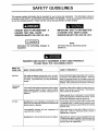
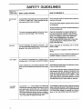
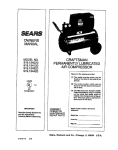
_ARS
CRAFTSMAN
GENERAL MANUAL FOR
PERMANENTLY LUBRICATED
TANK MOUNTED
TWIN CYLINDER
AIR COMPRESSOR
NOTE: For identification of Re)air Parts, see separate Parts
List Manual.
Record in the spaces provided,
(1) The mode_ number which can be
found on the maintenance label on
the top of the motor cover or on the
tank,
(2) The code number which can be
found on the foil label on the rear of
the air tank.
(3) The Manufacturers Number is located on the metal data plate which
is welded onto the backside of the
air tank. (This data plate is painted
the same color as the tank.)
Retain these numbers for future
reference.
IMPORTANT:
Read the Safety Guidelines
and All Instructions
Carefully
SAFETY GUIDELINES
ASSEMBLY
OPERATION
MAINTENANCE
TROUBLESHOOTING
REPAIR PARTS
Model No.
Code No.
Mfg. No.
Before Operating
Sears, Roebuck
I MG-PERMTWIN
6/18/93 I
and Co., Chicago,
IL 60684
U.S.A.
TABLE OF CONTENTS
Page
WARRANTY
...............................................................................................................................
SAFETY GUIDELINES
WARNING
...............................................................................................................
2
3
CHART .....................................................................................................................
3
...............................................................................................................................
5
GLOSSARY
ACCESSORIES
FOR USE WITH SEARS AIR COMPRESSORS
GENERAL INFORMATION
DESCRIPTION
ASSEMBLY
...............................................
........................................................................................................
OF OPERATION
...............................................................................................
................................................................................................................................
REMOVAL OF SHIPPING
BOARDS AND INSTALLATION
........................................................
5
5
6
7
7
INSTALLATION AND BREAK-IN PROCEDURES ......................................................................
Location of Air Compressor ..................................................................................................
Lubrication and Oil ................................................................................................................
Extension Cords ...................................................................................................................
Voltage and Circuit Protection ..............................................................................................
Grounding Instructions .........................................................................................................
7
7
7
8
8
8
OPERATING
9
PROCEDURES
....................................................................................................
MAINTENANCE .......................................................................................................................
Air Filter- Inspection and Replacement ..............................................................................
Check Valve -Replacement ................................................................................................
Safety Valve - Inspection ....................................................................................................
Motor ..................................................................................................................................
Storage ..............................................................................................................................
10
10
10
10
11
11
TROUBLESHOOTING
12
GUIDE .................................................................................................
HOW TO ORDER REPAIR PARTS .....................................................................
16
FULL ONE YEAR WARRANTY
ON
AIR COMPRESSORS
If this air compressor fails due to a defect in material orworkmanship within one year from the date of purchase, RETURN
IT TO THE NEAREST SEARS SERVICE CENTER/DEPARTMENT
THROUGHOUT THE UNITED STATES AND SEARS
WILL REPAIR IT, FREE OF CHARGE,
If this air compressoris used for commercial or rental purposes,the warrantywill apply for ninetydays from the date of
purchase.
This warrantygives you specificlegal rightsand you may have other rightswhich vary from state to state.
Sears, Roebuck and Co., Sears Tower, Dept. 731CR-W,
Chicago, IL 60684
SAFETY
GUIDELINES
This manual contains information that is important for you to know and understand. This information relates to
protecting YOUR SAFETY and PREVENTING EQUIPMENT PROBLEMS. To help you recognize this information,
we use the following symbols. Please read the manual and pay attention to these sections.
URGENT SAFETY INFORMATION
- A
HAZARD THAT WILL CAUSE
SERIOUS INJURY OR LOSS OF LIFE.
IMPORTANT
SAFETY INFORMATION
A HAZARD THAT MIGHTCAUSE
SERIOUS INJURY OR LOSS OF LIFE.
NOTE
Information
equipment.
for
HAZARDS
WHAT TO
LOOK FOR
Hot Parts
preventing
damage
to
information that you should pay special
attention to.
CAN OCCUR IF EQUIPMENT
IS NOT USED PROPERLY.
PLEASE READ THE FOLLOWING
CHART.
WHAT COULD HAPPEN
HOW TO PREVENT
IT
The metal compressorcomponents,such as mani- Avoid contact with metal components of the compresfold, tubes, etc., become hotwhen the air compressor sor during or immediately after operation, Reaching
is running. If you touch them, you may be seriously under or removing portions of the plastic enclosures
such as the filter cover and console cover exposes hot
burned.
surfaces. Attowcompressor to cool prior to servicing.
Flammable
Vapors
It is normal forthe motorandpressure switchto spark
when compressorstartsor stops.A spark can ignite
vapors from gasolineor solvents, causing a fire or
explosion.
If spraying a flammable material, provide ample ventilation. Never spray in a closed area. There must be
a flow of fresh air at all times.
Always operate the air compressor in well-ventilated
areas, freeofgasolineorothersolventvapors.
Do not
operate the compressor near the spray area.
Air Tank
Modifications to air compressor components in an
attempt to reach higher air pressure can cause the air
tank to rupture or explode.
Do not adjust, remove or tamper with the safety valve
or pressure switch. If safety valve or pressure switch
replacement is necessary, a part with the same ratings
must be used.
Incompatability
between tank and compressor will
cause the tank to rupture.
Never replace the air tank with a different model or a
larger tank. Return to Authorized Service Center if
replacement is required.
Modifications to the air tankwill cause ittc weaken.
Never drill into weld or in any way modify the air tank.
Thetankmay
rupture or explode. Ifleaks deve op due
to corrosion or tank is damaged, return to Authorized
Service Center for replacement.
3
SAFETY
WHAT TO
LOOK FOR
Compressed
Air
GUIDELINES
WHAT COULD HAPPEN
HOW TO PREVENT
IT
Compressed aircan propel dust, dirt or loose particles
it comes in contact with. These propelled particles
may cause serious injury or damage.
Never point any nozzleor sprayertowarda personor
any part of the body.
Alwayswear safety gogglesor glasseswhenusingthe
air compressor.
Always turnthe air compressoroffb_ore attachingor
removing accessories.
Electricity
Too much air pressure appliedto air toolsor accessories can cause damage or risk of bursting.
Check the manufacturer's pressure rating for air
tools and accessories. Regulator outl_ pressure
must never exceed the maximum pressure rating.
NOTE: IF A REGULATOR IS NOT SUPPLIED
WITH YOUR COMPRESSOR, YOU MUST
INSTALL ONE BEFORE USING AIR TOOLS AND
ACCESSORIES WITH PRESSURE RATINGS
LESS THAN 200 PSIG,
Your air compressor is powered by electricity. Like
any other electrically powered device, if it is not used
properly it may cause electrical shock.
Always unplug the air compressorprior to maintenance or repair.
Never use the air compressor outdoors when it is
raining.
Always plug the cord into an electrical outlet with the
specified voltage and adequate fuse protection.
Toxic Vapors
It is normal for compressed air to contain toxic or
irritatingvapors. Suchvapors are harmful if inhaled.
Never directlyinhalethe compressedair producedby
this unit.
Certain materials you are spraying (like paint, weed
killer, sandor insecticide)can be harmfulif you inhale
them.
Read labels and safetydatafor all materialsyouspray.
Followall safety precautions.
Use a mask or respirator ifthera is a chance of inhaling
toxic sprayed materials. Masks and respirators have
limits and will only provide protection against some
kinds and limited amounts of toxic material, Read
mask and respirator instructions carefully. Consult
with a safety expert or industrial hygienist if you are not
sure about the use of a certain mask or respirator.
Unsuitable
Solvents
4
The solvents1,1,1 - Trichloroethaneand Methylene Ifthe material you intend to spray contains the solvents
Chlodde canchemically reectwith aluminumused in listed at left (read the label or data sheet), do not use
)aint spray guns, paint pumps, etc., and cause an accessories that contain aluminum or galvanized parts.
explosion.These solventscan also react with galva- You must either change the material you intend to
nizedcomponentsand cause corrosionand weaken- spray, or use only stainless steel spray equipment.
ingof parts. This does not affectyourair compressor
- but it may affect the equipmentbeing used.
GLOSSARY
CFM: Cubic feet per minute.
SCFM: Standard cubicfeet per minute; a unit of measure
of air delivery.
PSIG: Pounds per square inch gauge; a unit of measure
of pressure.
ASME: American Society of Mechanical Engineers;
made, tested, inspected and registered to meet the
standards of the ASME.
Cut-In Pressure: While the motor is off, air tank pressure
drops as you continue to use your accessory. When the
tank pressure drops to a certain low level the motor will
restart automatically. The low pressure at which the
motor automatically re-starts is called =cut-in pressure."
Cut-Out Pressure: When you turn on your air compressor and it begins to run, air pressure in the airtank begins
to build. It builds to a certain high pressure before the
motor automatically shuts off - protecting your air tank
from pressure higher than its capacity. The high pressure
at which the motor shuts off is called =cut-out pressure."
U.L. Listed: This product is Listed by UndenNriters
Laboratories, Inc. (UL). Samples of this product have
been evaluated by UL and meet the applicable UL Standards for Safety.
ACCESSORIES
FOR USE WITH
SEARS AIR COMPRESSORS
The following acoessodes are available through the current general sale catalog or at full-line Sears stores.
.SPRAYGUNS
.BLOWGUNS
•AIR CAULKING GUNS
.POWERWASHER
.SANDBLASTERS
*AIR BRUSHES
•AIR LINE FILTERS
•TIRE AIR CHUCKS
•PAINT TANKS
-AIRTANKS
.INFLATORKITS
•QUICK CONNECTOR SETS
(various sizes)
.VISCOSIMETER
•AIR PRESSURE REGULATORS
•OIL FOG LUBRICATORS
-AIRTOOLS:
Sanders
DdUs
Impact Wrenches
Hammers
•AIR HOSE:
114", 5/16" or 3t8" I.D.
in vadous lengths
GENERAL
INFORMATION
You have purchased an air compressor unit consisting of
a 2 cylinder, single-stage air compressor pump and air
tank. Included with portable compressors only are an air
hose, tire air chuck, wheels, regulator, gauges, and
handle. Stationary units are not supplied with regulators.
This air compressor requires no oil. Now you can enjoy
all the benefits of having an air compressor without ever
having to purchase, add or change oil.
Youraircompressor
.NAILER/STAPLERS
Decking
Farming
Roofing
Siding
Finishing
Carpenting
Upholstery
Picture Framing
•DRAIN CLEANER
.DUSTERGUN
guns, air tools, caulking
sandblaster, or inflating
weed killers, insecticides,
required for most of the
guns, grease guns, air brushes,
tires and plastic toys, spraying
etc. An air pressure regulatoris
applications.
An air filter which removes moisture and dirt from the
compressed air should be used where applicable.
These accessories can be purchased from most Sears
stores.
can be used foroperating paint spray
5
DESCRIPTION
OF OPERATION
Air Compressor Pump: To compress air, the pistons
move up and down in the cylinders. On the downstroke,
air is drawn in through the air intake valves. The exhaust
valves remain dosed. On the upstroke of the piston, air
iscompressed. The intake valves close and compressed
air is forced out through the exhaust valves, through the
outlet tubes, through the check valve and intothe air tank.
Working air is not available until the compressor has
raised the air tank pressure above that required at the air
outlet.
Check Valve: When the air compressor is operating, the
check valve is =open", allowing compressed air to enter
the air tank. When the air compressor reaches =cut-out"
pressure, the check valve =closes", allowing air pressure
to remain inside the air tank.
Pressure Release Valve: The pressure release valve
located on the side of the pressure switch, is designed to
automatically release compressed air from the compressor head and the outlet tube when the air compressor
reaches =cut-out" pressure or is shut off. If the air is not
released, the motorwill not be able to start. The pressure
release valve allowsthe motorto restart freely. When the
motor stops running, air will be heard escaping from the
valve for a few seconds. No air should be leaking when
the motor is running.
Pressure Switch: The pressure switch automatically
starts the motor when the air tank pressure drops below
the factory set =cut-in" pressure, It stopsthe motorwhen
the air tank pressure reaches the factory set "cut-out"
pressure,
Globe Valve: Turn the knob counter-clockwise
the valve and clockwise to close.
Safety Valve: If the pressure switch does not shut off the
air compressor at its cut-out pressure setting, the safety
valve will protect the tank against high pressure by
=popping out = at its factory set pressure (slightly higher
than the pressure switch cut-out setting).
Regulator:. The air pressure coming from the air tank is
controlled by the regulator. Turn the regulator knob
clockwise to increase pressure and counter-clockwise to
decrease pressure. To avoid minor readjustment after
making a change in pressure setting, always approach
the desired pressure from a lower pressure. When
reducing from a higher to a lower setting, first reduce to
some pressure less than that desired, then bdng up to the
desired pressure. Depending on the air requiroments of
each particular accessory, the outlet regulated air pressure may have to be adjusted while operating the accessory.
Outlet Pressure Gauge: The outlet pressure gauge
indicates the air pressure available at the outlet side ofthe
regulator. This pressure is controlled by the regulator and
is always tess or equal to the tank pressure. See
"Operating Procedures'.
Tank Pressure Gauge: The tank pressure gauge indicates the reserve air pressure in the tank.
Cooling System:
This compressor contains an advanced design cooling system. At the heart of this cooling
system is an engineered fan. It is perfectly normal for this
fan to blow air through the vent holes in large amounts.
You know that the cooling system is working when air is
being expelled.
to open
Tools Needed for Assembly
• a 9/16" socket or open end wrench for attaching the wheels or removing shipping beards
• a 3/8" open end wrench or socket to tighten handle screws
6
ASSEMBLY
Installing Wheels,
Strip
FOR PORTABLE COMPRESSORS
Handles, Rubber Foot
THE WI-IEELS AND HANDLE DO NOT PROVIDE ADEQUATE
CLEARANCE, STABILITY OR SUPPORT FOR PULLING THE UNIT
UP AND DOWN STAIRS OR STEPS. THE
UNIT MUST BE LIFTED, OR PUSHED UP A
RAMP.
Attach the handle to the compressor saddle by inserting the handle inside the compressor saddle and
lining up the two bolt holes on each side. Install the
four screws, two on each side. Tighten securely.
H may be necessary to brace or support one
end of the outfit when attaching the wheels
and the rubber foot strip because the air
compressor will have a tendency to tip.
Install one shoulder bolt and one nut for each wheel
2.
using upper bolt hote for 30 and 33 gallon units.
Tighten securely. The outfit will sit level if the wheels
are propedy installed.
3.
Clean and dry air tank leg opposite wheels. Remove
the protective paper stdp from the adhesive backed
rubber foot strip. Attach the rubber foot strip to the
bottom of leg. Press firmly into place.
REMOVAL OF SHIPPING BOARDS AND INSTALLATION
FOR STATIONARY (PERMANENTLY MOUNTED) UNITS
2_
It may be necessary to brace or support one
side of the outfit when removing the shipping boanJs because the air compressor will
have a tendency to tip.
,
This compressor is designed to be bolted directly to a
level floor. Prior to installing, place the newwashers
which are supplied with the compressor, between the
feet and floor such that the dng base at the bottom of
the tank does not contact the floor. Tighten bolts 1520 tt. tbs.
Remove all packaging such that only the compressor
on the pallet remains. Remove and discard the (4)
screws and washers that hold the compressor to the
pallet.
INSTALLATION AND BREAK-IN
Location of
the Air Compressor
Locate the air compressor in a clean, dry and well
ventilated area. The air filter must be kept clear of
obstructions which could reduce air delivery of the air
compressor, The air compressor should be located at
least 12" away from the wall or other obstructions that will
interfere with the flow of air. Theaircompressorheadand
shroud are designed to allow for proper cooling.
Lubrication
and
Oil
This unit needs no lubrication or oiling.
PROCEDURES
Break-In Procedures
The procedure is required only once, before the compressor is put into service. Operate the compressor with the
regulator or shut-offvalve fully open for 15 minutes. Make
sure that no pressure is building in the tank. After 15
mintues, close the regulator or shut-off valve and allow
the tankto fill to cut-out pressure and then the motor will
stop. Your compressor is now ready for use.
Extension
Cords
Use extra air hose instead of an extension cord to avoid
voltage drop and power loss to the motor, and to prevent
overheating.
If an extension cord must be used, be sure it is:
a 3-wira extension cord that has a 3-blade grounding
plug, and a 3-slot receptacle that will accept the plug
on the product
The portable air compressor is equipped with a cord
having a grounding wire with an appropdate grounding
plug. The plug must be used with an outlet that has been
installed and grounded in accordance with all local codes
and ordinances. The outlet must have the same configuration as the plug. See illustration. DO NOT USE AN
ADAPTER.
Inspect the plug and cord before each use. Do not use if
there are signs of damage.
in good condition
no longer than 50 feet
12 gauge (AWG) or larger. (Wire size increases as
gauge number decreases. 10 AWG and 8 AWG may
also be used. DO NOT USE 14 OR 16 AWG.)
Voltage and Circuit Protection
Refer to your Parts List Manual for the voltage and circuit
protction requirements of your compressor, Use only a
fuse or circuit breakerthat isthe same rating as the branch
circuit the air compressor is operated on. If the compressor is connected to a circuit protcted by fuses, use only
dual element time delay fuses, as noted in that Service
Bulletin.
Refer to Parts List Manual for your compressor. Certain
air compressor models can be operated on a 15 amp
circuit if:
1.
2.
3.
4.
Voltage supply to circuit is normal.
Circuit is not used to supply any other electdcal needs
(lights, appliances, etc.).
Extension cords comply with specifications.
Circuit is equipped with a 15 amp circuit breaker or 15
amp time delay fuse. Use a Fusetron Type T time
delay fuse.
If any of the above conditions cannot be met, or if
operation of the compressor repeatedly causes interruption of the power, it may be necessary to operate it from
a 20 am p circuit. It is not necessary to change the cord set.
IMPROPER GROUNDING
ELECTRICAL SHOCK.
CAN RESULT IN
Do not modify the plug that has been provided. If it
does not fit the available outlet, the correct outlet
should be installed by a qualified electrician.
If repairing or replacing cord or plug, the grounding
wire must be kept separate from the current-carrying wires. Never connect the grounding wire to a fiat
blade plug terminal. The grounding wire has insulation with an outer surface that is green - with or
without yellow stripes.
If these grounding instructions are not completely
understood, or if in doubt as to whether the compressor is propedy grounded, have the installation
checked by a qualified electrician.
120Volt Model_
24e Volt Medel=
WhU=
=ll AM_ P,,IKI
15
GROUNDOIG_
AMP PI.UG
_ OLrTt'ET
OUTUET
Gt;IOU_
PIN
Fm
GROUNDING
- Portable
INSTRUCTION
Compressors
Wiring Instructions - Stationary (Permanently
Mounted) Compressors
RISK OF ELECTRICAL SHOCK. in the event of
a shortcircuit,groundingreduces the risk of shock
by providingan escape wire for the electriccurrent.
This air compressor must be properly grounded.
If your compressor is not equipped with a plug-in type
power cord, perform electdcal wiring according to the
following instructions:
Refer to the Specification Chart in the Outfit Parts
Bulletin for your compressor.
RISKOF ELECTRICAL
SHOCK.
IMPROPER
ELECTRICAL GROUNDING CAN RESULT IN
ELECTRICAL SHOCK. WIRING FOR THE PRESSURE SWITCH SHOULD BE DONE BY A LICENSED ELECTRICIAN IN ACCORDANCE WITH
NATIONAL AND LOCAL CODES AND ORDINANCES.
2.
Install the compressor as close to the main power supply
as possible. This practice will avoid using long lengths of
electrical widng for the power supply which can cause
power loss to the motor. When connecting wires, make
sure that :
Widng must be such that full motor nameplate voltage
plus or minus 10% is available at the motor terminals
during starting. Refer to local codes for recommended
wire sizes for correct wire size and maximum wire run;
undersize wire causes high amp draw and overheating to
the motor.
Electrical wiring must be located away from hot
surfaces such as manifold assembly, compressor outlet tubes, beads, or cylinders.
1. The amperage rating of the electrical box is adequate.
OPERATING
1.
2.
PROCEDURES
Before attaching air hose or acoessodes, make sure
the OFF/AUTO lever is set to "OFF" and the air
regulator or globe valve is closed.
Attach hose and accessories.
TOO MUCH AIR PRESSURE CREATES A HAZARDOUS RISK OF BURSTING. CAREFULLY
FOU.OW STEPS 3 AND 5 EACH TIME THE
COMPRESSOR IS USED.
Compressed air from the outfit may contain
water condensation.
Do not spray untiltered air at an item that could be damaged.
Some air operated tools or devices may
require filtered air. Read the instructions
for the air tool or device.
3.
The supply line has the same electdcal characteristics (voltage, cycle, phase) as the motor.
Check the manufacturer's maximum pressure rating
for air tools and accossodes. The regulator outlet
pressure must never exceed the maximum pressure
rating. If your compressor is not supplied with a
regulator with gauge, install one before using accessories.
4.
Turn the OFF/AUTO leverto"AUTO" and allowtank
pressure to build. Motor will stop when tank pressure
reaches =cut-out" pressure.
5.
Openthe regulatorbytuming it clockwise. Adjustthe
regulator to the correct pressure setting. Your com-
pressor is ready for use.
6.
Always operate the air compressor in well-ventilated
areas; free ofgasoline orothersolvent vapors. Do not
operate the compressor near the spray area.
When you are finished:
7, Setthe"OFFIAUTO"leverto=OFF ".
8. Turn the regulator counterclockwise and set the
outlet pressure to zero.
9. Removethe airtool or accessory.
10. Open the regulator and allow the air to slowly bleed
from the tank. Close the regulator when tank pressure is approximately 20 psi.
11. Drain waterfrem airtank.
WATER WILL CONDENSE IN THE AIR TANK.
IF NOT DRAINED, WATER WILL CORRODE
AND WEAKEN THE AIR TANK CAUSING A
RISK OF AIR TANK RUPTURE.
With tank pressure at approximately 20 psi, open the
drain cock or drain valve.
NOTE:
If drain cock valve is plugged, release all air
pressure. The valve can then be removed,
cleaned, then reinstalled.
12. After the water has been drained, close the drain
cock or drain valve. The air compressor can nowbe
stored.
9
MAINTENANCE
iiiii
UNIT CYCLES AUTOMATICALLY
WHEN POWER IS ON. WHEN DOING MAINTENANCE, YOU MAY BE
EXPOSED TO VOLTAGE SOURCES, COMPRESSED AIR OR MOVING PARTS. PERSONAL INJURIES CAN
OCCUR.
BEFORE PERFORMING ANY MAINTENANCE OR REPAIR, UNPLUG THE COMPRESSOR
AND
BLEED OFF ALL AIR PRESSURE.
ALLMAINTENANCEAND REPAIROPERATIONSNOTLISTEDMUST BEDONEBY QUALIFIEDSERVICEPERSONNEL.
Air
Filter
- Inspection
and
Replacement
Check
Valve
Replacement
- Portable
Compressors
Hot surfaces. Risk of burn. Compressor
heads are exposed when filter cover is
removed. Allow compressor to cool prior
Risk of personal injury. Mainfold assembly
contains compressed air which can be hxTardous.
Manifold gets hot during operation.
Before servicing:
•Unplug or disconnect electdcel supply to
compressor.
-Bleed tank of pressure.
•Allow compressor to cool.
to servicing. _
Keep the air filter clean at all times. Do not operate the
compressor with the air filter removed.
A dirty air filter will not allowthe compressor to operate at
full capacity. Before you use the compressor, check the
air filter to be sure it is clean.
t.
2.
3.
4.
Check Valve - Replacement - Stationary
(Permanently Mounted) Compressors
1.
Release all air pressure frcm air tank and disconnect
outfit from supply circuit.
2. Remove rear shroud.
3. Remove tubes and compression fittings at the tee
and remove the tee from the check valve.
4. Remove the pressure release tube and fitting from
the check valve.
5. Unscrew from the check valve (turn counterclockwise) using a socket wrench.
6. The check valve may be cleaned with a solvent, such
as paint and varnish remover.
7. Apply sealant to the check valve threads. Reinstall
the check valve (turn clockwise).
DO NOT
OVERTIGHTEN.
8. Replace the pressure release tube, fitting and tee.
9. Replace the outlet tubes and tighten fittings.
10, Replace the shroud.
11. Connect compressor to supply circuit,
10
Release all air pressure from air tank and unplug
outfit.
Remove console cover.
Loosen lower ouUet tube nuts that secure outtet tubes
to the upper manifold section.
Remove the six screws secudng the upper manifold
section to the lower section.
5.
Lift upper manifold assembly and invert so that the
flapper valve and o-dng are exposed.
6. Remove the two small screws secudng the flapper
valve and restdctor.
7. Replace flapper valve and re-assemble restdctor and
two screws.
8. Assemble upper manifold assembly to the lower
section. Make sure the o-dng is retained in the upper
section as it is inverted and the outlet tube slides into
the upper section. Tighten six screws.
9. Tighten lower outfit tube nuts.
10. Replace console cover.
Safety Valve - Inspection
If the safety valve does not work properly,
over-pressurization may occur, causing air
tank rupture or an explosion. Before starting
compressor, pull the ring on the safety valve
to make sure that the safety valve operates
fTeely. If the valve is stuck or does not operate
smoothly, it must be replaced with the same
type of valve.
MAINTENANCE
(cont'd)
Storage
The motor has an automatic msat thermal overload
protector. If the motor overheats for any reason, the
ovedoad protector will shut off the motor. The motor
must be allowed to cool down before restarting. The
compressor will automatically restart after the motor
cools.
Before you store the air compressor,
the following:
1.
make sure you do
Review the =Maintenance" and "Operating Procedures" sections and perform maintenance as necessary. Be sure to drain water from the air tank.
Protect the electrical cord and air hose from damage
(such as being stepped on or run over). Wind them
loosely around the compressor handle.
If the ovedoed protector shuts the motor off frequently,
check for a possible voltage problem. Lowvoltage can
also be suspected when:
2.
1.
2.
Store the air compressor in a clean and dry location.
The motor does not get up to full power or speed.
Fuses blow out when starting the motor; lights
dim and remain dim when motor is started and is
running.
11
Illllllll
TROUBLESHOOTING
GUIDE
PERFORMING
REPAIRS MAY EXPOSE VOLTAGE SOURCES, MOVING PARTS OR COMPRESSED AIR SOURCES. PERSONAL INJURY MAY OCCUR. PRIOR TO ATTEMPTING ANY
REPAIRS, UNPLUG THE COMPRESSOR AND BLEED OFF TANK AIR PRESSURE.
PROBLEM
CAUSE
CORRECTION
Excessivetank pressure- safety
valve pops off.
Pressureswitchdoesnot shut offmctor
when compressorreaches "cut-out"
pressure.
Movethe pressureswitchlevertothe'OFF =position.
If the outt'rtdoesn'tshutoff, andtheelectricalcontacts
are welded together, replacethe pressureswitch.
Pressure switch'cut-out" too high.
Return the outfit to Sears Service Center to check
and adjust, or replace switch.
Air leaks at fittings.
Tube fittings are not tight enough.
Tighten fittings where air can be heard escaping,
Check t'rttings with soapy water solution, DO NOT
OVER-TGHTEN.
Airleaks atorinsidecheckvaive,
Defective or dirty check valve.
A defective check valve results in a constant air leak
at the pressure release valve where there is pressure
in thetank and the compressor is shut off. Remove
and clean or replace check valve.
Air leaks at pressure switch release valve.
Defective pressure switch release Remove and replace the release valve.
valve.
If the contacts are good, checkto see if the pin in the
bottom of the pressure release valve is stuck. If it
does not move freely, replace the valve,
Airleaks in airtank orat airtank
welds.
Defective check valve.
A defective check valve results in a constant air leak
at the pressure release valve when there is pressure
in thetank and the compressor is shut off. Remove
and clean or replace check valve.
Defectiveair tank.
Air tank must be replaced. Do not repair the leak.
DO NOT DRILL INTO, WELD OR OTHERWISE
MODIFY AIR TANK OR IT WILL WEAKEN, THE
TANK CAN RUPTURE OR EXPLODE.
Air leaks between head and
valve plate,
Pressure reading on the regulated pressure gauge drops
when an accessory is used.
Leaking seal.
tt is normal for"some" pressure drop
to occur.
Torque head screws to 8 ft. Ibs. If this does not
stop leak, replace seal.
If there is an excessive amount of pressure drop
when the accessory is used, adjust the regulator
following the instructions on page 6.
NOTE
Adjust the regulated pressure under flow condilions (while accesory is being used).
12
TROUBLESHOOTING
GUIDE
(Continued)
PROBLEM
CAUSE
CORRECTION
Air leak from safety valve.
Possible defect in safety valve.
Operate safety valve manually by puning on ring. tf
valve still leaks, it should be replaced.
Knocking Noise
Defective check valve.
Remove and clean, or replace,
Compressor is not supplying
enough air to operate accessories.
Prolonged excessive use of air.
Decrease amount of air usage,
Compressor is not large enough for air
requirement.
Check the accessory air requirement. If it is higher
than the SCFM or pressure supplied by your air
compressor, you need a larger compressor.
Restricted air intake filter,
Clean or replace air intake filter. Do not operate the
air compressor in the paint spray area.
Hole in hose,
Check and replace if required.
Check valve restricted.
Remove and clean, or replace.
Air leaks.
Tighten f_ings.
(See Air Leaks Section of Troubleshooting Guide,)
Motor overload protection switch has
tripped.
Let motor cool off and overload switch will automati-
Tank pressure exceeds pressure
switch"cut-in" pressure.
Motor will start automaticatly when tank pressure
drops below "cut-in" pressure of pressure switch.
Wrong gauge wire or length of extension cord.
Check for proper gauge wire and cord length.
Check valve stuck open.
Remove and clean, or replace.
Loose electrical connections.
Check wiring connection inside pressure switch and
terminal box area.
Possible defective motor or capacitor.
Return to Sears Service Center for inspection or
replacement, if necessary.
Motor will not run or restart.
Paint spray on internal motor parts.
Regulator knob continuous air
leak, Regulator will not shut off
at air outlet.
cally reset.
Have checked at Sears Service Center. Do not
operatethe compressorin the paint spray area. See
flammablevaporwarning,
Fuse blown, circuit breaker tripped.
1_ Check fuse box for blown fuse and replace, if
necessary. Reset circuitbreaker, Do not usea
fuse orcircuitbreakerwithhigherratingthanthat
specifiedfor your particularbranch circuit.
2. Check for properfuse; only "Fusetron"type T
fuses are acceptable.
3. Check for low voltage conditionsand/or proper
extensioncord,
4, Disconnectthe other electricalappliancesfrom
circuit or operate the compressorin its own
branchcircuit,
Pressure release valve on pressure
switch has not unloaded head pressure.
Bleed the line by pushing the lever on the pressure
switch tothe=ofr' position; ifthevalve does not open,
replace it.
Broken exhaust valve.
Remove head and valve plate, inspect and replace
if necessary,
Dirty or damaged regulator internal
)arts.
Clean or replace regulator,
or internal parts.
13
SERVICE NOTES
14
SERVICE NOTES
m
15
_ VRS
GENERAL
MANUAL
FOR
CRAFTSMAN
PERMANENTLY
LUBRICATED
TANK MOUNTED
AIR COMPRESSOR
SERVICE
MODEL
NO.
HOW TO ORDER
REPAIR PARTS
Now that you have purchased your Sears Air Compressor, should a
need ever exist for repair parts or service, simply contact any Sears
Service Center and most Sears, Roebuck and Co. stores, Be sure to
provide all pertinent facts when you call or visit.
The model number of your Sears Air Compressor can be found on the
label which is located on the top of the motor cover or on the tank.
WHEN ORDERING REPAIR PARTS, ALWAYS
LOWING INFORMATION:
GIVE THE FOL-
• PART NUMBER
• PART DESCRIPTION
• MODEL NUMBER
• NAME OF ITEM
All parts listed may be ordered from any Sears Service Center and
most Sears stores.
If the parts you need are not stocked locally, your order will be
electronically transmitted to a Sears Repair Parts Distribution Center
for handling.
Sears,
Roebuck and Co.,
Chicago,
IL 60684
U.S.A.