1
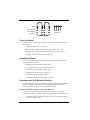
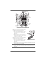
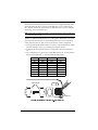
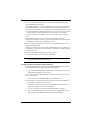
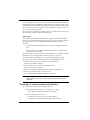
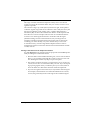
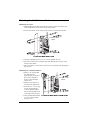
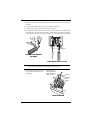
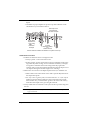
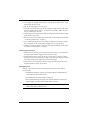
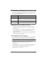
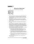
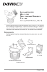
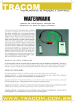
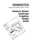
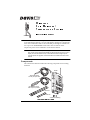
IRELESS
S OIL M OISTURE /
T EMPERATURE S TATION
W
I NSTA LLA TION M AN UAL
The Wireless Soil Moisture/Temperature Station, referred to in this document
as the Soil Moisture Station, is for use with Wireless Vantage Pro® Weather Stations. One Soil Moisture Station can be installed per Vantage Pro Weather Station. Up to four WATERMARK soil moisture sensors and four multitemperature probes can be installed in a Soil Moisture Station.
Note: The Soil Moisture Station requires Vantage Pro console firmware dated Oct 25
2001 or later. (Press and hold the DONE key then press the UP arrow (+) key to
display the console firmware level.) Contact Davis Technical Support if your
console requires an upgrade. Contact information is located in the back of this
manual.
Components
The Soil Moisture Station includes the following components and mounting
hardware:
Shelter
Temperature Probe
with 15' (4.6 m) of cable
Soil Moisture Sensor
with 15' (4.6 m) of cable
8" Cable Ties
4" Cable Ties
3-Volt Lithium Battery
Soil Moisture Station Components
Product # 6361
U-Bolts
1/4" Flat Washers
1/4" x 1-1/2"
Lag Screws
1/4" Lock Washers
1/4" Hex Nuts
Mounting Hardware
Tools for Setup
In addition to the components shown, you will need some or all of the following materials:
• Adjustable wrench or 7/16" wrench
• Ballpoint pen or paper clip (small pointed object of some kind)
• Drill and 3/16" (5 mm) drill bit (if mounting on a vertical surface)
• Stepped Sensor Installation Tool (see page 13)
Installation Steps
For ease of installation and use of your Soil Moisture Station, please follow
steps in the order presented.
• Preparing the Soil Moisture Station, page 2
• Choosing a location to mount the station, page 6
• Mounting the Soil Moisture Station, page 8
• Installing soil moisture sensors, page 10
• Using soil moisture readings, page 15
• Troubleshooting soil moisture sensors, page 15
Preparing the Soil Moisture Station
The following illustration shows the location of the DavisTalk transmitter DIP
Switches, the battery mounting location, and the terminal blocks used to
connect the soil moisture sensors and temperature probes.
Inserting the Battery and Connecting the Sensors
1. Insert the 3-volt lithium battery into the battery holder, matching the “+”
sign on the battery with the “+” sign next to the battery mounting brackets.
• Note the location of the DIP switches. You will work with them during
the next installation step.
Page 2
Wireless Soil Moisture/ Temperature Station
3-Volt
Lithium Battery
DIP
Switches
Terminal
Blocks
Sensor Interface Module on Soil Moisture Station
2. Temporarily connect a temperature probe to
the TEMP 1 terminal block connector.
• Use a pen or small screwdriver to open
the connector “jaws” as shown in the
illustration.
• While the jaws are open, insert the temperature probe leads, then let the connector jaws close in on the lead.
3. Temporarily connect a soil moisture probe to
the SOIL 1 terminal block connector.
• Use a pen or small screwdriver to open
the connector “jaws” as shown in the
illustration.
Connecting the Sensor Cable
• While the jaws are open, insert the temperature probe leads, then let the
connector jaws close in on the lead.
Note: At least one temperature probe or soil moisture sensor need to be temporarily
installed in order to test communications between the Soil Moisture Station and
the console.
Preparing the Soil Moisture Station
Page 3
Setting the DavisTalk Transmitter ID
Each wireless transmitting station must be set to one of eight DavisTalk transmitter IDs. DIP switches #1, 2 and 3 on the SIM allow you to control the ID —
the “channel” the station will transmit on. (DIP switch #4 is used for transmission testing, not for transmitter ID.)
Note: A DavisTalk transmitter and receiver communicate with each other only when both
are set to the same ID.
The factory default transmitter ID is ‘1’. Looking at the table below, you can see
that means the DIP switches are in the OFF position when each transmitting
station leaves the factory. This is true for all of Davis’ wireless equipment.
1. Verify the DavisTalk channel used by your ISS, as well as all other DavisTalk
channels already in use by your Vantage Pro Weather Station.
2. Configure the Soil Moisture Station to a DavisTalk channel not already in
use.
3. Use a ballpoint pen or paper clip to toggle DIP switches #1, 2, and 3. The settings for transmitter IDs 1 – 8 are shown in the table below:
ID CODE
SWITCH 1
SWITCH 2
SWITCH 3
#1 (default)
#2
#3
#4
#5
#6
#7
#8
OFF
OFF
OFF
OFF
ON
ON
ON
ON
OFF
OFF
ON
ON
OFF
OFF
ON
ON
OFF
ON
OFF
ON
OFF
ON
OFF
ON
.
Battery Holder
ON
1
2
3
4
DIP Switches
DavisTalk Transmitter DIP Switches in Top-right Corner of SIM
Page 4
Wireless Soil Moisture/ Temperature Station
Setting Console/Receiver(s) to Same ID
1. Put your console into Setup Mode — press and hold the DONE key and
press the DOWN (-) arrow key.
The console will show you Screen 1: Transmitters. You should see the words:
“RECEIVING FROM...” and “STATION NO.” followed by the transmitter
IDs that your console detects. One of these should be the ID number you just
set on the Soil Moisture Station transmitter. If you don’t see it, make sure the
console is within 10' of the transmitter, and verify that you set the DIP
switches correctly. If you still don’t see it, go to “TEST mode” on the next
page.
2. Press the DONE key to move on to Screen 2: Selecting Transmitters.
Setup Mode – Screen 2 is where you will set the console to recognize signals
on that ID as coming from a Soil Moisture Station.
3. Press the LEFT (<) or RIGHT (>) arrow key, or the STATION key, to scroll
through transmitter IDs.
When you see the ID you chose for the Soil Moisture Station, use the UP (+)
or DOWN (-) arrow keys to activate reception of that ID code. Make sure the
screen shows “ON”.
4. Press the GRAPH key until the word “SOIL” appears.
5. To exit Setup Mode, press and hold the DONE key.
Note: See the Vantage Pro User’s Manual & Setup Guide: “Setup Mode – Screen 2:
Selecting Transmitters” for more information.
Testing Soil Moisture Station Communications
1. Press the TEMP key until you see “SOIL MOIST” displayed on the console
screen where the inside temperature is usually displayed.
• If you see SOIL MOIST and no number, you are seeing the moisture and
temperature readings for sensor pair #1.
2. If you continue to press the TEMP key, you will see the readings for sensor
pairs #2, #3, and #4.
• If no sensors are installed the reading will be dashed out.
3. A soil moisture or temperature reading confirms communication between
your Soil Moisture Station and the console.
• Disconnect the soil moisture sensor and temperature probe that were
temporarily installed to test communications.
• Go on to “Choosing a Location to Mount the Station” on page 6.
If your console does not show a soil moisture or soil temperature reading, proceed to “Troubleshooting Communication Problems
Preparing the Soil Moisture Station
Page 5
Troubleshooting Communication Problems
First, verify that the console/receiver is powered and is not in Setup Mode (exit
Setup Mode by pressing DONE key and holding it for a moment). Then, on the
Soil Moisture Station, check that the battery is properly installed. Walk around
the room with the console, standing for a few moments in various locations to
see if you are picking up signals.
If you don’t see any readings, no matter where you stand with the console, put
the transmitter in TEST mode as described below.
TEST mode
DIP switch #4 on the SIM (see illustration on page 4) is the TEST DIP-switch.
Switch it to the ON position using a ball-point pen or paper clip. This puts the
transmitter in Test Mode. An LED indicator light will flash each time it
transmits:
• The LED will immediately flash once to show that the light itself functions.
• Then it will flash each time the transmitter broadcasts a signal, which
should be every 10 seconds.
If the LED flashes only once and then remains dark, there is a problem with the
transmitter. See “Contacting Davis Technical Support” on page 15.
If the LED flashes repeatedly but your console isn’t picking up a signal
anywhere in the room, it could be related to one of the following causes:
1. The DIP switches were not correctly set on the transmitter.
Review the procedure on page 4.
2. The ID was not correctly set on the console/receiver.
Review the procedure on page 5.
3. Reception is being disrupted by RF (radio frequency) interference.
4. There is a problem with the console/receiver.
See “Contacting Davis Technical Support” on page 15.
Note: Remember to turn the Test DIP switch OFF when you’re finished testing
wireless transmission. If it is left ON, the blinking LED will reduce battery life
significantly.
Choosing a Location to Mount the Station
Try to position you Soil Moisture Station as follows:
• Within transmission range of your Vantage Pro console.
• See “Range of Wireless Transmission” on page 7
• Within cable range of the sensors.
• Sensors come with 15’ (4.6 m) of cable standard.
• Maximum recommended cable length is 1000’ (300 m).
Page 6
Wireless Soil Moisture/ Temperature Station
Range of Wireless Transmission
The range of wireless transmission depends on many factors. For the best
reception, position the transmitter shelter and your console/receiver as close
together as possible.
The maximum range is up to 400' (120 m) in the line of sight, under optimal
conditions. Typical range under most conditions is 100' to 200' (30 to 60 m), but
this may be reduced by walls, ceilings, trees, or foliage. Radio-frequency
interference (RF) can also reduce transmission distance. Cordless phones and
ham radios are common examples of devices that can cause RF interference.
A metal roof or other large metal structure can interfere with the signal
(aluminum siding, a furnace with metal ducts, and your refrigerator are
examples). Sometimes transmission between wireless units is obscured by
something you cannot identify, or by some obstacle that you can’t work
around. If necessary, consider using Wireless Repeater #7624 or #7625 to
strengthen the signal or increase the distance between the transmitter and the
console/receiver.
Testing Transmission from Proposed Location
It is very important to test reception from the proposed location before permanently mounting the Soil Moisture Station.
• Place the shelter at the intended mounting site, or have someone hold it
there, so you can walk around with the console/receiver for a few minutes. Rotating the antenna may help to improve reception.
• Test wireless reception anywhere you might want to use or mount your
console/receiver now or in the future. Take your time. If you aren’t picking up strong signals where you intend to place your console, better to
move the shelter now than after it has been mounted. Experiment.
• If you have irregular terrain in the area, it may interfere with the signal.
For example, if the transmitter is mounted downhill from the console/
receiver, the ground may block a wide angle of the transmitted signal.
Choosing a Location to Mount the Station
Page 7
Mounting the Soil Moisture Station
Mounting on a Pole
1. While holding the shelter against the pole, place a U-bolt around the pole
and through the two holes on at the top of the shelter.
2. Place a flat washer, a lock washer and a hex nut on each of the bolt ends.
Flat
Washer
Hex
Lock Nut
Washer
U-Bolt
Mounting Soil Moisture Station on a Pole
3. Using an adjustable wrench or 7/16" wrench, tighten the nuts.
4. Place the second U-bolt around the pole and through the two holes at the
bottom of the shelter.
5. Put a flat washer, a lock washer, and a hex nut on each bolt end, and tighten
the hex nuts.
Mounting on a Vertical Surface
1. With a 3/16" (5 mm) drill
bit, drill two holes
approximately 2" (50 mm)
apart. Use a carpenter’s
level to ensure the holes
will be level.
Lag
Flat Screw
Washer
2. Drill two more holes 7-1/
32" below the upper holes.
3. Insert the 1/4" x 1-1/2" lag
screws through the flat
washers, and through the
holes at the top and bottom
of the shelter into the post.
4. Using an adjustable wrench
or 7/16" wrench, tighten
the lag screws.
Page 8
Mounting Soil Moisture Station on a Vertical Surface
Wireless Soil Moisture/ Temperature Station
Connecting the Sensors
1. Run the sensor cables up through the grommets on the bottom of the station
housing.
2. Connect the temperature probes to the TEMP connectors.
3. Connect soil moisture probes to the SOIL connectors
4. Each matched temperature probe and soil moisture pair must use the matching connectors. If a temperature probe is not used, the soil moisture reading
can be off as much as 1% for every 1°F (0.5°C) error in the soil temperature.
Grommets
Connecting Sensor Cables to the
Terminal Block
Sensor Cables Run through Grommets
Note: If no soil temperature probe is used, the console will use a default temperature of
75ºF (24ºC) to compensate the soil moisture sensor readings.
5. Secure sensor cables to the cable
tie mounts located next to the
grommets.
When tightening
cable tie, make sure
cables are on top of
cable tie mount.
Cable Tie
Cable Tie
Mount
Securing Sensor Cables
Mounting the Soil Moisture Station
Page 9
6. To prevent fraying or cutting of cables,
secure them so they will not whip about in
the wind. Secure a cable to a metal pole by
wrapping electrical tape around them both.
Make sure cables are secure by placing clips
or ties approximately every 3 – 5' (1 – 1.6 m).
Cable Tie
Cable Clip
Securing Cables with Clips and Ties
Note: Do not use metal staples or a staple gun to secure cables. Metal staples —
especially when installed with a staple gun — have a tendency to cut the cables.
Installing Soil Moisture Sensors
The soil acts as a reservoir to store water between irrigations, or rainfall, so that
it is available to the crop or plants as needed for healthy growth. The purpose
of using sensors to measure the soil water is to give you a better understanding
of how fast water is being depleted in the different areas of your field or lawn,
so you can better schedule your irrigations and correctly evaluate the true
effectiveness of any rainfall. By monitoring the soil moisture between irrigations, you will gain a more accurate picture of this process over time, and
develop an irrigation scheduling pattern to meet your crop’s “need” for water.
This minimizes the guesswork, resulting in water savings, lower pumping
costs, and the elimination of excess leaching of nitrogen due to over irrigation.
While not absolutely necessary for operation, we recommend that a
temperature probe be installed with each soil moisture sensor. This allows the
soil moisture sensor’s readings to be temperature compensated for better
accuracy.
Note: WATERMARK Soil Moisture Sensor application information based on material
supplied by Irrometer Company, Inc.
Locating Sensors
Be aware of the soil variations in your field or lawn. The lighter soils dry very
quickly, heavier soils more slowly. Both conditions must be considered.
Furrow or Flood Irrigation
• Sensors are usually placed about 2/3 of the way down the run, just
ahead of the tail or backup water. This is the area where water penetration is usually the poorest.
• In tree crops, place the sensors on the drier side of the tree exposed to the
most sun. In the Northern Hemisphere, this is typically the Southwest
side of the tree, which is exposed to the hot afternoon sun.
Page 10
Wireless Soil Moisture/ Temperature Station
Sprinkler Irrigation
• Sprinkler irrigation usually provides a more uniform distribution of
water to the ground surface, but there can be great differences in penetration and holding capacity due to soil type variations, soil interfaces
and contour. Try to place your sensors in the areas where variations
occur.
• In tree crops, locate sensors at the drip line.
• In row crops, locate sensors right in the plant row.
• Be sure that sensors are not located behind obstructions, such as tree
limbs, which would interfere with water distribution to the sensor area.
• With center pivots, place sensors at 4 locations down the length of the
pivot, just in front of the "start" point.
• Place sensors at "hot spots" or "good production" areas being sure to stay
in active root zones.
Drip or Micro Irrigation
• Place sensors in the wetted area. With drip emitters, this is usually 12” to
18” from the emitter.
• With micro-sprinklers or sprays, usually 24” to 36” from the micro-sprinkler is best.
Sensor Depths
Sensor depth depends on the rooting depth of your crop, and also depends on
soil depth and texture.
• With shallow rooted (less than 12”) vegetable crops, one depth may be
adequate.
• Deeper rooted row crops, small grains, vines, and trees need to be measured in at least two depths.
• With deep well-drained soils, crops generally root deeper if moisture is
available.
Installing Soil Moisture Sensors
Page 11
• With coarse, shallow or layered soils, root systems may be limited in
depth.
• Guidelines on proper depths for specific crops and conditions can be
obtained from your local farm advisor.
Some crops need
measurement at
more than one depth
Sensor depth
dependent on:
• crop rooting
depth
• soil texture
and depth
Co-locate
temperature probes
and
moisture sensors
Sensors must be located in the effective root system of the crop
Installation Procedure
1. Soak the soil moisture sensors overnight in water.
• Always “plant” a wet soil moisture sensor.
• If time permits, wet the soil moisture sensor for 30 minutes in the morning and let dry until evening, wet for 30 minutes and let dry overnight,
wet again for 30 minutes the next morning and let dry again until
evening. Soak over the next night and install wet. This will improve sensor response during the first few irrigations or waterings.
2. Make sensor access holes to the depth required with a 7/8” diameter rod.
• Make a hole for the soil moisture sensor and a separate adjacent hole for
the temperature probe.
• For very coarse or gravely soils, an oversize hole of 1” to 1 1/4” may be
needed to prevent abrasion damage to the soil moisture sensor membrane. In this case, you will need to “grout in” the sensor with a slurry
made from the sample soil to get a snug fit in the soil.
3. Always install sensors in the active root system of the crop with a snug fit in
the soil.
CAUTION:In gravelly soils and with deeper sensors, carefully install the sensor to prevent damaging the membrane.
Page 12
Wireless Soil Moisture/ Temperature Station
• Lack of a snug fit is the biggest problem in obtaining good soil moisture
sensor readings.
• The ideal method of making the access hole
is to have a stepped tool. This makes an
oversize hole for the upper portion and an
exact sized hole at the bottom where the sensor is located.
4. After installing the soil moisture sensor, the hole
needs to be carefully backfilled and tamped
down to prevent air pockets which could allow
water to channel down to the sensor.
• Fill the hole with water and push the sensor
down into the hole so it bottoms out.
A length of 1/2” Class 315 PVC tubing fits
snugly over the sensor collar and can be
used to push the sensor. A good snug fit in
the soil is important.
• Carefully backfill the access hole with soil to
eliminate any air pockets.
5. You can solvent weld the 1/2” Class 315 PVC
tubing to the sensor collar for easier installation
and removal.
• Use a PVC/ABS cement (IPS
Weld-on #794 or equivalent).
6. After you have installed the soil
moisture sensors, the sensors will
need one or two irrigation cycles to
“break-in” and acclimate to the soil
conditions and provide better accuracy.
Cold rolled steel,
round rod
1-1/4" (32 mm)
approximate
diameter
Overall length
variable
2-1/2" (64 mm)
7/8" (22.5 mm)
Stepped Sensor
Installation Tool
Tape
Sensor
Wires
1/2" PVC Pipe
Pipe welded to
sensor collar with
PVC/ABS cement
Soil Moisture
Sensor
PVC Pipe Welded to Soil Moisture
Sensor Collar
Installing Soil Moisture Sensors
Page 13
Installation Procedure for Turf/Lawns
1. Cut a slight “V” shaped trench about 5” wide at the top and about 6” deep
into the turf--about 6” long.
2. Lift out the turf plug piece you just cut.
3. Press the sensors into the soil at about a 45 degree angle into the side of the
trench to set the sensors about 3”-5” below the soil surface. Make sure they
are good and snug in the soil.
4. Set the plug removed from the trench and compact it back into place. It will
repair itself in short order.
5. Run the wires to the Soil Moisture Station and connect them as described in
“Connecting the Sensors” on page 9.
6. If you withhold irrigation for several days and allow the soil to dry down a
bit, you should see the soil moisture readings start to creep upward.
7. Usually, you will not need to water the turf until the reading is in the 25-40
area at the recommended 3”-5” depth.
Removing the Sensors
1. When removing sensors prior to harvest in annual crops, it’s a good idea to
do this just after the last irrigation when the soil is moist.
2. Do not pull the sensor out by the wires. You may have to dig out, at least
partially, any sensors more than 12” deep or any sensors in dry soil. Careful
removal prevents sensor and sensor membrane damage.
3. When sensors are removed for winter storage, clean the sensors, dry them,
and place them in a clean, dry location.
Wiring Sensors
Both the soil moisture sensors and the temperature probes come with 15’
(4.6 m) cables.
• If additional wiring is required, up to 1000’ (300 m) of additional wire
can be spliced onto the sensor wire.
• The additional wire must be fully waterproof.
• We recommend using #18 gauge wire with UF insulation, and using a
3M Scotchpak or Duraseal heat shrink splice connector.
Note: Avoid long wire runs near power cables. The transient currents can affect the
small current used to read the sensors.
Page 14
Wireless Soil Moisture/ Temperature Station
Using Soil Moisture Readings
Use this table as a general guide to interpret soil moisture readings. Monitoring
the soil moisture readings, and comparing them to your field or lawn conditions over time, will help you develop a better understanding of how to interpret your soil moisture readings.
Centibar Reading
Soil Condition
0-10
Saturated Soil. Occurs for a day or two after irrigation.
10-20
Soil is adequately wet (except coarse sands which are drying out at this range)
30-60
Usual range to irrigate or water (except heavy clay soils). Irrigate at the upper
end of this range in cool humid climates and with higher water-holding capacity
soils.
60-100
Usual range to irrigate heavy clay soils
100-200
Soil is becoming dangerously dry for maximum production. Proceed with caution.
Troubleshooting the Soil Moisture Sensor
Use these tests to verify the correct operation of your soil moisture sensor:
1. With the sensor submerged in water, the station should show a reading
between 0 and 5.
2. Let the sensor air dry for 30 to 48 hours. Depending on ambient temperature, humidity, and air movement, the reading should be 150 or over.
3. Put the sensor back in the water. The reading should run right back to 0 to 5
within 1 to 2 minutes.
4. If the sensor does not pass these tests, please contact Davis Technical Support for help in resolving the problem.
Contacting Davis Technical Support
If you have questions about your Soil Moisture Station, or encounter problems
installing or operating the station, please contact Davis Technical Support.
Note: Please do not return items to the factory for repair without prior authorization.
(510) 732-7814 – Monday – Friday, 7:00 a.m. – 5:30 p.m. Pacific Time.
(510) 732-9229 – For callers outside the USA or Canada.
(510) 670-0589 – Fax.
www.davisnet.com – Copies of User Manuals are available on the “Support”
page. Watch for FAQs and other updates. Subscribe to the e-newsletter.
[email protected] – E-mail to Technical Support.
[email protected] – General e-mail.
Using Soil Moisture Readings
Page 15
Specifications
• Soil Moisture range: 0 to 200 centibars
• Temperature range (Station & Temp Probe): –40 to 140° Fahrenheit (–40
to 60° Celsius)
• Temperature range (Soil Moisture Sensor): 32 to 105° Fahrenheit (0 to 40°
Celsius)
• Primary power input: Solar power – Davis solar charger
• Secondary (backup) power: CR-123A 3-volt lithium battery
• Wireless transmission frequency: 916.5 MHz
• 868.35 MHz for overseas version – Product # includes “OV”
• Transmitter ID codes: 8 user-selectable
• License: low power (less than 1 mW), no license required
FCC Part 15 Class B Registration Warning
This equipment has been tested and found to comply with the limits for a class B digital device, pursuant to
Part 15 of the FCC Rules. These limits are designed to provide reasonable protection against harmful interference in a residential installation. This equipment generates, uses and can radiate radio frequency energy
and, if not installed and used in accordance with the instructions, may cause harmful interference to radio
communications. However, there is no guarantee that interference will not occur in a particular installation.
If this equipment does cause harmful interference to radio or television reception, which can be determined
by turning the equipment off and on, the user is encouraged to try to correct the interference by one or more
of the following measures:
•
Reorient or relocate the receiving antenna.
•
Increase the separation between the equipment and receiver.
•
Connect the equipment into an outlet on a circuit different from that to which the receiver is connected.
•
Consult the dealer or an experienced radio/TV technician for help.
Changes or modifications not expressly approved in writing by Davis Instruments may void the user's
authority to operate this equipment.
Product Numbers: 6361
Davis Instruments Part Number: 7395.145
Wireless Soil Moisture/ Temperature Station
(Rev A, 11/13/01)
This product complies with the essential protection requirements of the EC EMC Directive 89/336/EC.
Copyright © 2001 Davis Instruments Corp. All rights reserved.
The WATERMARK soil moisture sensor is a product of Irrometer Company, Inc.
3465 Diablo Avenue, Hayward, CA 94545-2778
510-732-9229 • Fax: 510-732-9188
E-mail: [email protected] • www.davisnet.com