1
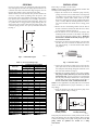
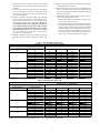
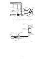
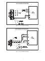
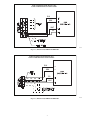
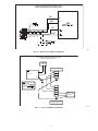
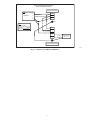
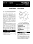
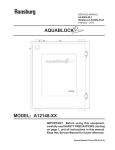
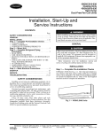
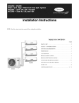
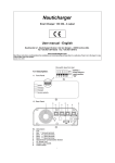
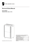
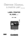
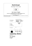
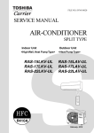
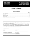
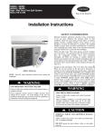
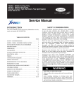
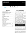
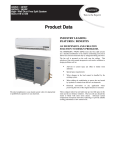
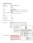
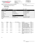
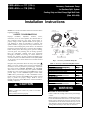
53DS---900--- --- ---117 (115 v)
53DS---900--- --- ---118 (230 v)
Accessory Condensate Pump
for Ductless Split System
Cooling Only and Heat Pump High Wall Units
(Size 009---036)
Installation Instructions
NOTE: Read and become familiar with these instructions before
beginning installation.
Condensate Pump
Assembly
16’ Transparent
Suction Discharge Tubing
Low Voltage
Power Cord
SAFETY CONSIDERATIONS
Improper
installation,
adjustment,
alteration,
service,
maintenance, or use can cause explosion, fire, electrical shock, or
other conditions which may cause death, personal injury, or
property damage. Consult a qualified installer, service agency, or
your distributor or branch for information or assistance. The
qualified installer or agency must use factory--authorized kits or
accessories when modifying this product. Refer to the individual
instructions packaged with the kits or accessories when installing.
Follow all safety codes. Wear safety glasses, protective clothing,
and work gloves. Use quenching cloth for brazing operations.
Have fire extinguisher available. Read these instructions
thoroughly and follow all warnings or cautions included in
literature and attached to the unit. Consult local building codes
and current editions of the National Electrical Code (NEC) NFPA
70. In Canada, refer to current editions of the Canadian electrical
code CSA 22.1.
Recognize safety information. This is the safety--alert symbol !!
When you see this symbol on the unit and in instructions or
manuals, be alert to the potential for personal injury. Understand
these signal words; DANGER, WARNING, and CAUTION.
These words are used with the safety--alert symbol. DANGER
identifies the most serious hazards which will result in severe
personal injury or death. WARNING signifies hazards which
could result in personal injury or death. CAUTION is used to
identify unsafe practices which would result in minor personal
injury or product and property damage. NOTE is used to
highlight suggestions which will result in enhanced installation,
reliability, or operation.
!
CAUTION
UNIT OPERATION HAZARD
Failure to follow this caution may result in unit failure
and/or damage.
Always follow instructions properly.
Detection Unit
Mounting Bracket
Adhesive
Mounting Bracket
Detection Unit
5/8” Rubber Elbow
Wire Ties (6)
Transparent
Detection
Unit Vent Tubing
Power Cable
A12227
Fig. 1 --- Accessory Condensate Pump Kit
Table 1—Accessory Condensate Pump Kit Contents
ITEM
QTY
16--- ft Transparent Suction/Discharge Tubing
1
Condensate Pump Assembly
1
Low--- Voltage Power Cord
1
Transparent Detection Unit Vent Tubing
1
Power Cable
1
Wire Ties
6
Wall Mount Bracket
1
Adhesive
1
Detection Unit Mounting Bracket
1
5/8--- in Rubber Elbow
1
Detection Unit
1
!
WARNING
ELECTRICAL SHOCK HAZARD
Failure to follow this warning could result in personal injury
or death.
Before beginning any modification or installation of this kit,
be sure the main electrical disconnect is in the OFF position.
Ensure power is disconnected to the fan coil unit. On some
systems both the fan coil and the outdoor unit may be on the
same disconnect. Tag the disconnect switch with a suitable
warning label. There may be more than one disconnect.
GENERAL
INSTALLATION
Use the two--part accessory kit (condensate pump and detection
unit) with high wall fan coils. The pump operates whenever the
condensate level in the detection unit is high enough to cause the
magnetic float switch to send a signal to start the pump.
The float switch in the detection unit also prevents overflow and
can act as a safety device by shutting down the system. The
detection unit comes with normally closed (NC) alarm contacts
(user optional, but recommended). The normally closed alarm
contact is a dry contact rated for 8 amps at 250 volts. In the event
of a problem such as a clogged drain or pump discharge line, the
alarm contact can be wired to shut down the entire system. The
condensate pump provides 10 ft (3.0 m) maximum suction lift
(A)--Fig. 2.
Refer to Fig. 1 and Table 1 for kit content.
NOTE: To make the installation easier, install the detection unit
assembly before installing the fan coil unit.
1. Unpack the contents of the condensate pump accessory
package. Attach the 5/8--in. rubber elbow and transparent
vent tubing to the detection unit (see Fig. 6). If straight
connection is required, rubber elbow can be cut to size.
Do not use a tube longer than the one supplied with the kit
(2.95” / 75 mm). Slide the mounting bracket onto the bottom of the detection unit. Uncoil the low voltage power
cord.
2. Remove the fan coil mounting bracket from the back of
the unit. Connect the detection unit with the 5/8--in. elbow,
to the condensate drain line (see Fig. 6).
3. Peel the adhesive cover on the back of the detection unit
mounting bracket and attach it to the inside of the unit adjacent to the fan coil drain as shown in Fig. 6. Make sure
the detection is installed horizontally for proper operation of the float switch.
4. Attach one end of the transparent tubing to the detection
unit. The tube can be connected to either the front or the
rear as shown in Fig. 3. block the unused outlet with the
plug supplied.
B
C
Pump
A
Detecon
Unit
A12134
Fig. 2 --- Maximum Lengths
A09398
Table 2—Accessory Package Usage
Fig. 3 --- Detection Unit
ACCESSORY MODEL NUMBER
BASE UNIT
53DS--- 900--- --- --- 117
(115--- 1--- 60)
WIRING FIG. NO.
40GXC(Q)009--- --- --- 1
40GXC(Q)012--- --- --- 1
40GXC(Q)018--- --- --- 3
40GXC(Q)024--- --- --- 3
40GXM009--- --- --- 3
40GXM012--- --- --- 3
40GXM018--- --- --- 3
40MVC(Q)009--- --- --- 1
40MVC(Q)012--- --- --- 1
40MVC(Q)012--- --- --- 3
40MVC(Q)018--- --- --- 3
40MVC(Q)024--- --- --- 3
40QNC(Q)030--- --- --- 3
40QNC(Q)036--- --- --- 3
40QNC018024--- --- --- 3
40QNQ018--- --- --- 3
40QNQ024--- --- --- 3
PW3C(H)AM009
PW3C(H)AM012
PW3C(H)NM018
PW3C(H)NM024
RAS--- 09LKV--- UL
RAS--- 12LKV--- UL
RAS--- 15LKV--- UL
RAS--- 17LKV--- UL
RAS--- 22LKV--- UL
RAV--- SP180KRT--- UL
RAV--- SP240KRT--- UL
11
11
15
15
15
15
15
8
8
9 or 10
10
10
8
8
10
10
15
15
15
15
15
15
15
5. Connect one end of the low voltage power cord to the telephone jack socket in the detection unit and route the cord
and transparent drain tubing through the knockout on the
side of the unit enclosure (see Fig. 6).
6. Determine the mounting location of the pump assembly.
The pump assembly must always be above the level of
the detection unit. For best operation, it is recommended
that the pump assembly be mounted in a vertical position
with the flow arrow on the pump pointing up (see Fig. 7).
Do not exceed 10 ft. (3.0 m) maximum suction lift.
NOTE: in most applications, the pump will need to be mounted
outside of the highwall unit for proper orientation ( i.e. above
drop ceiling).
7. Screw the bracket to the wall and attach the pump to the
bracket as shown in Fig. 4 and Fig. 5.
53DS--- 900--- --- --- 118
(208/230--- 1--- 60)
WIRING FIG. NO.
13
13
13
13
13
12
13
13
14
14
14
14
14
13
13
16
16
16
16
16
16
16
Fig. 4 --- Pump
Assembly Vertical
Fig. 5 --- Pump
Assembly Horizontal
A12228
If the pump is not mounted in the vertical position, make sure that
plug on the pump is above the refrigerant tubing. This is required
to avoid water leaking onto the pump causing a short circuit. The
pump cannot be splashed nor located in a damp
environment.
2
8. Connect the other end of the low voltage power cord from
the detection unit to the telephone jack socket in the pump
assembly.
9. Cut the suction, transparent drain tubing after determining
where it will connect to the inlet side of the pump mounted on the wall. Remove the cap on the pump inlet and
connect draining tubing.
10. Attach the remaining transparent tubing to the discharge
side of the pump. Keep the pipe vertical for at least 4 or 5
inches and do not exceed the 33 ft (10 m) limit or the
value shown in (B) of Table 3 and Table 4. In order to
avoid siphoning action and running the pump dry, always connect the discharge tube to the drain at a higher level than the pump itself (pump should be higher
than detection unit). Be sure the condensate is discharged
to a safe location where the presence of water does not
pose any safety or health hazards.
11. Install the transparent vent tube (provided) on top of the
detection unit. Route tube so it will stay vertical (see Fig.
6).
12. Wire the pump and the alarm circuit using the appropriate
wiring diagram listed in Table 2.
13. Prime the pump at start--up and after each maintenance operation. To ensure proper operation, the suction pipe and
part of the discharge pipe must be slowly filled with water
using a squeeze bottle.
14. Test the unit. When the unit is mounted in place, the condensate pump system must be tested.
a. Be sure the Hi--Wall unit is installed on a level plane. Remove the front cover of the unit.
b. Slowly fill the condensate drain pan with water. Observe
the pump discharge tubing to be sure that the pump is operating. If condensate is not being discharged through the
discharge tubing, check to be sure that the lines are not
kinked or obstructed, and installation parameters have
been followed. If the optional alarm contact is wired, continue to pour water until the alarm circuit triggers.
Table 3—True Flow Rates (Gallons / Hr)
53DS--- 900--- --- --- 117, 118 Condensate Pump Flow Rates
Total tube length, 1/4” flexible hose (C)
Refer to Fig. 2 for (A), (B), (C)
ft
Suction Head (A)
Discharge Head (B)
15
30
60
ft
ft
0
5.0
4.7
4.5
6
4.2
3.9
3.7
13
3.0
2.9
2.8
0
20
2.5
2.0
26
1.6
1.3
33
1.1
0.9
0
3.7
3.4
3.2
6
2.9
2.6
2.4
3.3
13
0.5
1.8
1.6
20
1.2
1.1
0
2.9
2.6
2.4
6.6
6
2.4
2.1
1.8
13
1.5
1.3
0
2.6
2.4
2.1
10
6
2.1
1.8
1.6
13
1.3
1.1
100
4.2
3.5
2.6
1.7
1.1
0.7
2.9
2.1
1.3
2.1
1.6
1.2
1.8
1.3
Table 4—True Flow Rates (Liters / Hr)
53DS--- 900--- --- --- 117, 118 Condensate Pump Flow Rates
Total tube length, 1/4” flexible hose (C)
Refer to Fig. 2 for (A), (B), (C)
ft
Suction Head (A)
Discharge Head (B)
15
30
60
ft
ft
0
18.9
17.8
17.0
6
15.9
14.8
14.0
13
11.4
11.0
10.6
0
20
9.5
7.6
26
6.1
4.9
33
4.2
3.4
0
14.0
12.9
12.1
6
11.0
9.8
9.1
3.3
13
1.9
6.8
6.1
20
4.5
4.2
0
11.0
9.8
9.1
6.6
6
9.1
7.9
6.8
13
0.0
5.7
4.9
0
9.8
9.1
7.9
10
6
7.9
6.8
6.1
13
4.9
4.2
NOTE: Maximum suction plus discharge head is 33 ft (10 m). Longer lengths indicate horizontal condition.
3
100
15.9
13.2
9.8
6.4
4.2
2.6
11.0
7.9
4.9
7.9
6.1
4.5
6.8
4.9
POWER AND
ALARM CIRCUIT
CONNECTING
WIRES
DISCHARGE
TUBING
DETECTION
UNIT VENT TUBING
LOW VOLT
POWER CORD
FAN COIL CONDENSATE
DRAIN LINE
COMDENSATE
PUMP
ASSEMBLY
5/8" RUBBER
HOSE
DETECTION
UNIT
DETECTION UNIT
MOUNTING BRACKET
SUCTION TUBING
A12229
Fig. 6 --- Rear of High Wall Unit with Mounted Condensate Pump
PUMP DISCHARGE LINE
(PROVIDED)
(5) WIRES
(3) POWER L1, L2, G
(2) ALARM CIRCUIT
CONDENSATE PUMP
(RECOMMENDED
VERTICAL POSITION)
DISCHARGE
SUCTION
DETECTION DEVICE
(MUST BE MOUNTED HORIZONTALLY)
VENT TUBE
(PROVIDED)
LOW VOLT
POWER CORD
W/RJ11 CONNECTIONS
(TELEPHONE JACK)
FAN COIL
CONDENSATE
DRAIN LINE
PUMP SUCTION LINE
(PROVIDED)
5/8” RUBBER HOSE
(PROVIDED)
MOUNTING BRACKET
(PROVIDED)
A12230
Fig. 7 --- Accessory Condensate Pump Connections
4
115-1-60 POWER REQUIRED FOR PUMP
PUMP ALARM BREAKS SIGNAL
WHT
OUTDOOR UNIT
TERMINAL BLOCK
BRN
YEL
BLU
A12135
Fig. 8 --- 009, 012 (115--1--60) WIRING SCHEMATIC
115-1-60 POWER REQUIRED FOR PUMP
PUMP ALARM BREAKS SIGNAL
WHT
OUTDOOR UNIT
TERMINAL BLOCK
BRN
YEL
BLU
A12136
Fig. 9 --- (208/230--1--60) WIRING SCHEMATIC
5
115-1-60 POWER REQUIRED FOR PUMP
PUMP ALARM BREAKS SYSTEM POWER
WHT
BRN
YEL
BLU
A12137
Fig. 10 --- (115--1--60) WIRING SCHEMATIC
PUMP POWERED FROM INDOOR UNIT
PUMP ALARM BREAKS SYSTEM POWER
WHT
BRN
YEL
BLU
A12138
Fig. 11 --- (115--1--60) WIRING SCHEMATIC
6
PUMP POWERED FROM INDOOR UNIT
PUMP ALARM BREAKS SYSTEM POWER
BLU
BRN
WHT
YEL
A12139
Fig. 12 --- (208/230--1--60) WIRING SCHEMATIC
PUMP POWERED FROM INDOOR UNIT
PUMP ALARM BREAKS SYSTEM POWER
BLU
L2
BRN
L1
YEL
WHT
A12140
Fig. 13 --- (208/230--1--60) WIRING SCHEMATIC
7
PUMP POWERED FROM INDOOR UNIT
PUMP ALARM BREAKS SYSTEM POWER
BLU
L2
BRN
L1
YEL
WHT
A12141
Fig. 14 --- (208/230--1--60) WIRING SCHEMATIC
115-1-60 DEDICATED POWER SUPPLY FOR PUMP
PUMP ALARM BREAKS SIGNAL
115-1-60
Dedicated
Power Supply
Indoor Unit Terminal Block
Pump
115-1-60
L
L1
N
L2
AL
AL
S
GND
Legend
Field Power Wiring
Interconnecting Wiring
Pump Wiring
Field Splice Connection
L1
L2
S
L1
L2
Field Power Wiring
208/230-1-60
GND
Outdoor Unit Terminal Block
A12142
Fig. 15 --- (115--1--60) WIRING SCHEMATIC
8
PUMP POWERED FROM INDOOR UNIT
PUMP ALARM BREAKS SIGNAL
Indoor Unit Terminal Block
Pump
208/230-1-60
L1
L1
L2
L2
AL
AL
S
GND
Legend
Field Power Wiring
Interconnecting Wiring
Pump Wiring
Field Splice Connection
L1
L2
S
L1
L2
Field Power Wiring
208/230-1-60
GND
Outdoor Unit Terminal Block
A12143
Fig. 16 --- (208/230--1--60) WIRING SCHEMATIC
9
CLEANING AND MAINTENANCE
!
WARNING
ELECTRICAL SHOCK HAZARD
Failure to follow this warning could result in personal injury
or death.
Disconnect all power to unit to avoid possible electrical
shock during cleaning or maintenance. Set unit power
switch to OFF position.
Copyright 2012 CAC / BDP S 7310 W. Morris St. S Indianapolis, IN 46231
At the beginning of each season clean the detection unit.
1. Disconnect tubing and low voltage power cord from the
detection unit and slide unit out of mounting bracket
2. Remove the top of the detection unit and take out the float.
3. Clean the detection unit and the float using a solution of
water containing 5% bleach.
4. Replace the float in its original position with the magnet
side facing up.
5. Snap cover back into place.
6. Perform an operational test (see item 13 under installation
section).
Edition Date: 05/12
Manufacturer reserves the right to change, at any time, specifications and designs without notice and without obligations.
10
Catalog No: IIK---53DS900---CP---03
Replaces: IIK--- 53DS900--- CP--- 02