1
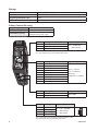
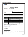
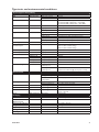
6651-2211
ODW-710-F2
Fibre Optic Modem
Industrial Converter
PROFIBUS DP to
Fibre Optic Link.
Point to Point applications
www.westermo.com
© Westermo Teleindustri AB
User Guide
Legal information
The contents of this document are provided “as is”. Except as required by applicable
law, no warranties of any kind, either express or implied, including, but not limited to,
the implied warranties of merchantability and fitness for a particular purpose, are made
in relation to the accuracy and reliability or contents of this document. Westermo
reserves the right to revise this document or withdraw it at any time without prior
notice.
Under no circumstances shall Westermo be responsible for any loss of data or income
or any special, incidental, and consequential or indirect damages howsoever caused.
More information about Westermo can be found at the following Internet address:
http://www.westermo.com
2
6651-2211
Safety
!
Before installation:
Read this manual completely and gather all information on the unit. Make sure
that you understand it fully. Check that your application does not exceed the safe
operating specifications for this unit.
This unit should only be installed by qualified personnel.
This unit should be built-in to an apparatus cabinet, or similar, where access is
restricted to service personnel only.
The power supply wiring must be sufficiently fused, and if necessary it must be
possible to disconnect manually from the power supply. Ensure compliance to
national installation regulations.
Branch circuit protection (fuse) is required for this unit with rating not
exceeding 20 A.
Product should be connected to UL Listed power supplies rated 12 – 48 VDC,
min 500 mA or 24 VAC, min 500 mA or reliably grounded DC SELV source*.
This unit uses convection cooling. To avoid obstructing the airflow around the
unit, follow the spacing recommendations (see Cooling section).
!
Before mounting, using or removing this unit:
Prevent access to hazardous voltages by disconnecting the unit from the power
supply.
Warning! Do not open a connected unit. Hazardous voltages may occur within
this unit when connected to a power supply.
!
Class 1 Laser Product
This unit is designed to meet the Class 1 Laser regulations. However, the user is warned
not to look directly into fibre optical fibre port or any connected fibre.
Care recommendations
Follow the care recommendations below to maintain full operation of the unit and to
fulfil the warranty obligations.
This unit must not be operated with covers or lids removed.
Do not attempt to disassemble the unit. There are no user serviceable parts inside.
Do not drop, knock or shake the unit. Rough handling beyond the specification may
cause damage to internal circuit boards.
Do not use harsh chemicals, cleaning solvents or strong detergents to clean the unit.
Do not paint the unit. Paint can clog the unit and prevent proper operation.
Do not expose the unit to any kind of liquids (rain, beverages, etc).
The unit is not waterproof. Keep the unit within the specified humidity levels.
Do not use or store the unit in dusty, dirty areas. Connectors as well as other
mechanical parts may be damaged.
If the unit is not working properly, contact the place of purchase, nearest Westermo
distributor office, or Westermo Tech support.
Fibre connectors are supplied with plugs to avoid contamination inside the optical port.
The plug should be fitted when no optical fibre is inserted in the connector, e.g. during
storage, service or transportation.
* Applicable for ODW-710-F2 only
6651-2211
3
Note. Fibre Optic Handling
Fibre optic equipment requires careful handling as the fibre components are very
sensitive to dust and dirt. If the fibre is disconnected from the modem, the protective
plug on the transmitter/receiver must be replaced. The protective plug must be kept on
during transportation. The fibre optic cable must also be protected in the same way.
If this recommendation is not followed, it can jeopardise the warranty.
Cleaning of the optical connectors
In the event of contamination, the optical connectors should be cleaned by using forced
nitrogen and some kind of cleaning stick.
Recommended cleaning fluids:
• Methyl-, ethyl-, isopropyl- or isobutyl-alcohol
• Hexane
• Naphtha
Maintenance
No maintenance is required, as long as the unit is used as intended within the specified
conditions.
Agency approvals and standards compliance
Type
Approval / Compliance
EMC
EN 61000-6-1, Immunity residential environments
EN 61000-6-2, Immunity industrial environments
EN 61000-6-3, Emission residential environments
EN 61000-6-4, Emission industrial environments
EN 55022, Emission IT equipment, class A
EN 55024, Immunity IT equipment
FCC part 15 Class A
EN 50121-4, Railway signalling and telecommunications apparatus
IEC 62236-4, Railway signalling and telecommunications apparatus
Safety
UL/CSA/IEC/EN 60950-1, IT equipment*
EN 60950-1, IT equipment**
ATEX**
EN 60079-0 and EN 60079-15
* Applicable for ODW-710-F2 only
** Applicable for ODW-710-F2 Ex only
FCC Part 15.105
Notice:
This equipment has been tested and found to comply with the limits for a Class A
digital device, pursuant to Part 15 of the FCC Rules. These limits are designed to provide
reasonable protection against harmful interference when the equipment is operated in a
commercial environment.
This equipment generates, uses, and can radiate radio frequency energy and, if not
installed and used in accordance with the instruction manual, may cause harmful interference to radio communications. Operation of this equipment in a residential area is likely
to cause harmful interference in which case the user will be required to correct the
interference at his own expense.
EN 55022 Notice: This is a class A product. In a domestic environment this product may cause radio interference in which case the user may be required to take adequate measures.
4
6651-2211
ATEX Information (Applicable for ODW-710-F2 EX only)
General
This unit is intended for use in Zone 2 hazardous location only.
Marking
II 3 G
Ex nA IIC T4 Gc
SPECIAL CONDITION
WARNING – DO NOT SEPARATE WHEN ENERGIZED
Indicate that this unit complies with relevant European standards that are
harmonised with the 94/9/EC Directive (ATEX).
II
3
G
Ex
nA
IIC
T4
Gc
SPECIAL
CONDITION
6651-2211
Equipment group II.
This unit can be installed in all places with an explosive gas atmosphere other
than mines susceptible to firedamp
Equipment category 3.
A category is the classification according to the required level of protection.
This unit ensures the requisite level of protection during normal operation and
is intended for use in areas in which explosive atmosphere caused by gases,
vapours, mists, or dust mixtures are unlikely to occure or, if they do occure, are
likely to do so only infrequently and for a short periode only.
Indicates protection concerning explosive atmospheres caused by gases,
vapours or mists (G).
Indicates that this unit is in conformity with relevant European Ex standard(s).
Type of protection used.
This unit is a non-sparking device "nA" which is constructed to minimize the
risk of occurence of arcs or sparks capable of creating an ignition hazard during
conditions of normal operation.
Gas group, a typical gas i hydrogen.
Temperature class T4 (T4 = 135°C).
This unit is classified in accordance with its maximum surface temperature
(external and internal).
Equipment protection level Gc (EPL Gc).
Equipment for explosive gas atmospheres, having a "enhanced" level of protection, which is not a source of ignition in normal operation and which may have
some additional protection to ensure that it remains inactive as an ignition
source in the case of regular expected occurences. EPL Gc are analogous to the
ATEX Categories (Category 3 G = EPL Gc).
This unit has a special condition of use.
The special condition for safe use contains safety related information that is
necesarry for the correct installation and safe use.
5
Ratings
Power
Ambient temperature
Ingress protection (IP)
Maximum surface temperatur
(12 – 48) VDC; 400 mA
–40ºC ≤ Ta ≤ +60ºC
IP21
135ºC (temperature class T4)
Safety Control Drawing
Degree of protection
Ambient temperature
Installation spacing
IP 21
–40°C to +60°C
Minimum 25 mm above / below
Minimum 10 mm left / right
Direction relative this unit!
Position
1
2
3
Descripton
In & out / Relay contact (NO)
In & out / Relay contact (C)
In & out / Relay contact (NC)
Input / Output values
Uin = 60 VDC max
Iin = 500 mA max
Galvanically isolated via mechanical relay.
See user manual for proven transient protection.
Descripton
–/–
–/–
In/out / RxD/TxD-P
Out / CNTR-P
– / DGND
Out / VP
–/–
In/Out / RxD/TxD-N
Not connected
Input / Output values
Umax = ± 5 Vpk
Imax = ± 400 mA
Data rate:
9600 bit/s to 12 Mbit/s
123
4
Position
1
2
3
4
5
6
7
8
9
Position Descripton
Rx
In / Receive port
Tx
Out / Transmit port
Position Descripton
1
In / Common
2
3
4
In / +Voltage A
In / +Voltage B
In / Common
Output values
Max 0 dBm
Input values
Uin = (10 – 60) VDC
Iin = 550 mA max
PIn = Max 5.5 W
See section Type tests and environmental conditions in this
user manual for proven transient protection.
6
6651-2211
SPECIAL CONDITION FOR SAFE USE
Ambient temperature:
This unit is designed for use in extreme ambient temperature conditions as follows:
–40 ºC ≤ Ta ≤ +60 ºC
Installation in an apparatus cabinet:
This unit requires installation in an Ex certified apparatus cabinet suitable for the area of use and
providing a degree of protection of at least IP54.
Resistance to impact:
This unit requires installation in an apparatus cabinet where adequate resistance to impact is
provided by the apparatus cabinet. See "Installation in an apparatus cabinet" above for requirements
on the external apparatus cabinet.
Resistance to light:
This unit requires installation in an apparatus cabinet where it is protected from light
(for example daylight or light from luminaires).
See "Installation in an apparatus cabinet" above for requirements on the external apparatus cabinet.
Secureness of plugs:
When this unit is installed in an explosive atmospheres, all connectors must be mechanically secured
to prevent loosening.
Conductor temperature:
When this unit is installed in locations with high ambient temperature, special precautions shall be
taken upon the choice of external conductors and the temperature rating of the conductor(s).
Directive 94/9/EC alongside with other directives:
Directive 2004/108/EC (EMC) applies and to assure a safe performance of this unit under the scope
of Directive 94/9/EC, refer to the electromagnetic immunity level specified under "Type tests and
environmental conditions" in this manual.
Standards and date of compliance
EN 60079-0 and EN 60079-15
2010-12-17
6651-2211
7
Declaration of Conformity
Westermo Teleindustri AB
Declaration of conformity
The manufacturer
Westermo Teleindustri AB
SE-640 40 Stora Sundby, Sweden
Herewith declares that the product(s)
Type of product
Model
Art no
Industrial fiberoptic repeaters/media
converters
ODW-700 series
3651-07xx
ODW-700EX series
3651-37xx
is in conformity with the following EC directive(s).
No
Short name
2004/108/EC
94/9/EC1
Electromagnetic Compatibility (EMC)
Equipment Explosive Atmospheres (ATEX)
References of standards applied for this EC declaration of conformity.
No
EN 61000-6-1
Title
Electromagnetic compatibility – Immunity residential environments
Issue
2007
EN 61000-6-2
Electromagnetic compatibility – Immunity industrial environments
2005
EN 61000-6-3
Electromagnetic compatibility – Emission residential environments
2007
EN 61000-6-4
2007
EN 55022
Electromagnetic compatibility – Emission for industrial
environments
Information technology equipment - Emission
EN 55024
Information technology equipment - Immunity
EN 50121-4
Railway applications – Electromagnetic compatibility – Emission
and immunity of the signalling and telecommunications apparatus
Explosive atmospheres – Equipment – General requirements
1998 + A1:2001 +
A2:2003
2006
EN 60079-0
EN 60079-15
Electrical apparatus for explosive gas atmospheres –
Construction, test and marking of type of protection “n” electrical
apparatus
The last two digits of the year in which the CE marking was affixed:
2006 + A1:2007
2009
2005
11
Pierre Öberg
Technical Manager
15th June 2011
1
8
Applicable for ODW-700EX series only.
Postadress/Postal address
Tel.
Telefax
Postgiro
Bankgiro
Org.nr/
Corp. identity number
Registered office
S-640 40 Stora Sundby
Sweden
016-428000
Int+46 16428000
016-428001
Int+46 16428001
52 72 79-4
5671-5550
556361-2604
Eskilstuna
6651-2211
Type tests and environmental conditions
Electromagnetic Compatibility
Phenomena
Test
ESD
EN 61000-4-2
RF field AM modulated
IEC 61000-4-3
RF field 900 MHz
Fast transient
ENV 50204
EN 61000-4-4
Surge
EN 61000-4-5
RF conducted
EN 61000-4-6
Pulse Magnetic field
Voltage dips
and interruption
EN 61000-4-9
EN 61000-4-11
Mains freq. 50 Hz
Mains freq. 50 Hz
Radiated emission
EN 61000-4-16
SS 436 15 03
EN 55022
FCC part 15
EN 55022
FCC part 15
EN 55022
EN 60950
Conducted emission
Dielectric strength
Environmental
Temperature
Shock
Packaging
Enclosure, ODW-710-F2
Enclosure,
ODW-710-F2 EX
Dimension W x H x D
Weight
Degree of protection
Cooling
Mounting
6651-2211
Enclosure
Signal ports
Power ports
Signal ports unbalanced
Signal ports balanced
Power ports
Signal ports
Power ports
Enclosure
AC power ports
Signal ports
Signal ports
Enclosure
AC power ports
AC power ports
DC power ports
Signal port to all other
isolated ports
Power port to other
isolated ports
IEC 60068-2-6
Operating
Storage & Transport
Maximum surface
temperature
Operating
Storage & Transport
Operating
Operating
Operating
IEC 60068-2-27
Operating
UL 94
PC / ABS
Cabelec 6141
Humidity
Altitude
Service life
Vibration
Description
Enclosure contact
Enclosure air
Enclosure
IEC 529
Enclosure
Level
± 6 kV
± 8 kV
10 V/m 80% AM (1 kHz), 80 – 800 MHz
20 V/m 80% AM (1 kHz), 800 – 1000 MHz
20 V/m 80% AM (1 kHz), 1400 – 2700 MHz
20 V/m pulse modulated 200 Hz, 900 ± 5 MHz
± 2 kV
± 2 kV
± 2 kV line to earth, ± 2 kV line to line
± 2 kV line to earth, ± 1 kV line to line
± 2 kV line to earth, ± 2 kV line to line
10 V 80% AM (1 kHz), 0.15 – 80 MHz
10 V 80% AM (1 kHz), 0.15 – 80 MHz
300 A/m, 6.4 / 16 µs pulse
10 & 5 000 ms, interruption
200 ms, 40% residual voltage
500 ms, 70% residual voltage
100 V 50 Hz line to earth
250 V 50 Hz line to line
Class B
Class A
Class B
Class B
Class A
2 kVrms 50 Hz 1min
3 kVrms 50 Hz 1min
2 kVrms 50 Hz 1min (@ rated power < 60V)
–40 to +60°C
–40 to +70°C
135ºC (temperature class T4)
5 to 95% relative humidity
5 to 95% relative humidity
2 000 m / 70 kPa
10 year
7.5 mm, 5 – 8 Hz
2 g, 8 – 500 Hz
15 g, 11 ms
Flammability class V-1
35 x 121 x 119 mm
0.26 kg
IP 21
Convection
Horizontal on 35 mm DIN-rail
9
Functional description
Switches
LED’s
POWER
+VA
+VB
COM
O
V
P
Internal Electronics
O
V
P
NO
C
NC
PROFIBUS DP
RxD/TxD-P
RxD/TxD-N
SHIELD
COM
STATUS
O
C
P
SFP
Fibre transceiver
SFP
Fibre transceiver
CH 1
TX
RX
CH 2
TX
RX
OVP Over Voltage Protection
OCP Over Current Protection
Converter PROFIBUS DP – optical fibre
ODW-710-F2 is a fibre optic modem that converts between electrical PROFIBUS DP and
a fibre optical link.
Repeater – optical fibre links
ODW-710-F2 is a fibre optic repeater that repeats received data from one fibre link out
to the other link. This is useful e.g. for long distance communication, where electromagnetic interference may occur or when isolation of the electrical network is needed. The
maximum optical fibre distance depends on selected fibre transceiver and fibre type.
Distances up to 80 km (50 miles) are available.
Data rate up to 12 Mbit/s
ODW-710-F2 converts PROFIBUS DP data using data rates from 9 600 bit/s up to
12 Mbit/s. Retiming of the PROFIBUS DP data ensures that the correct signal form is
transmitted from the ODW-710-F2 converter.
Automatic data rate detection
The PROFIBUS data rate is set automatically as soon as the ODW-710-F2 receives a
correct data frame, whether data is received from PROFIBUS DP or the fibre optic link.
The detected data rate remains until a number of consecutive faulty received frames have
been detected or no further frames are detected within the timeout period. The timeout
period is set by switches, with the default setting of 31 faulty frames or 5 seconds without any received frames.
10
6651-2211
Interface specifications
Power
Rated voltage
Operating voltage
Rated current
Rated frequency
Inrush current I2t
Startup current*
Polarity
Redundant power input
Isolation to
Connection
Connector size
Shielded cable
ODW-710-F2:
12 to 48 VDC and 24 VAC
ODW-710-F2 Ex: 12 to 48 VDC
ODW-710-F2:
10 to 60 VDC and 20 to 30 VAC
ODW-710-F2 Ex: 10 to 60 VDC
400 mA @ 12 VDC
200 mA @ 24 VDC
100 mA @ 48 VDC
ODW-710-F2:
DC and 48 to 62 Hz
ODW-710-F2 Ex: DC
0.2 A2s
1.0 Apeak
Reverse polarity protected
Yes
PROFIBUS DP and Status port
Detachable screw terminal
0.75 – 2.5 mm2 (AWG 18 – 13)
Connect the unit using at least 18 AWG (0.75 mm2) wiring
Not required
* External supply current capability for proper startup Status
Port type
Rated voltage
Operating voltage
Contact rating
Contact resistance
Isolation to
Connection
Connector size
Shielded cable
6651-2211
Signal relay, changeover contacts
Up to 48 VDC
Up to 60 VDC
500 mA @ 48 VDC
< 50 mW
PROFIBUS DP and Power port
Detachable screw terminal
0.2 – 2.5 mm2 (AWG 24 – 13)
Not required
11
PROFIBUS DP (RS-485)
Electrical specification
Data rate
Data format
Protocol
Data Rate detection
Retiming
Turn around time
Transmission range
Settings
Protection
Isolation to
Connection
Shielded cable
Conductive housing
EIA RS-485 / EN 50 170
9 600 bit/s, 19.2, 93.75, 187.5, 500 kbit/s, 1.5, 3, 6 and 12 Mbit/s
8 data bits, even parity, 1 stop bit, 11 bits total
PROFIBUS DP / EN 50170
Yes, compliant with EN 50 170
Yes
In accordance with EN 50 170
≤ 1200 m, depending on data rate and cable type (EIA RS-485)
None, external termination and failsafe biasing
Installation Fault Tolerant (up to ±60 V)
Power and Status port
9-pin D-sub female
Not required
Isolated to all other circuits and housings
Optical Power Budget
The allowed link length is calculated from the optical power budget (OPB), the available optical
power for a fibre-optic link, and the attenuation of the fibre, comprising losses due to in-line
connectors, splices, optical switches and a margin for link ageing (typical 1.5 dB for 1300 nm).
The worst-case optical power budget (OPB) in dB for a fibre-optic link is determined by the difference between the transmitter’s output optical power (min) and the receiver input sensitivity (max).
FX (Fibre)
Fibre connector
Fibre type
Wavelength
Transmitter
Output optical power min/max
Receiver
Input sensitivity, max
Receiver
Input optical power, max
Optical power budget,
worst-case
Transceiver type
Laser class
12
SM-LC80
LC duplex
Singlemode
9/125 mm
1550 nm
–5/0 dBm
SM-LC40
LC duplex
Singlemode
9/125 mm
1310 nm
–5/0 dBm
SM-LC20
LC duplex
Singlemode
9/125 mm
1310 nm
–15/–8 dBm
–35 dBm
–35 dBm
–34 dBm
MM-LC2
LC duplex
Multimode,
62.5/125 mm
1310 nm
–20/–14
dBm
–31 dBm
0 dBm
0 dBm
0 dBm
–8 dBm
30 dB
30 dB
19 dB
11 dB
Small Form Factor Pluggable (SFP)
Multi-Sourcing Agreement (MSA) compliant
Class 1, IEC 825-1 Accessible Emission Limit (AEL)
6651-2211
FX (Fibre)
Fibre connector
Fibre type
Wavelength nm, connector 1
Wavelength nm, connector 2
Transmitter
Output optical power min/max
Receiver
Input sensitivity, max
Receiver
Input optical power, max
Optical power budget,
worst-case
Bit error rate (BER)
Transceiver type
Laser class
6651-2211
Bi-Di
LC-40
LC Simplex
Singlemode
9/125 μm
Tx 1310, Rx 1550
Tx 1550, Rx 1310
–8/0 dBm
Bi-Di
LC-20
LC Simplex
Singlemode
9/125 μm
Tx1310, Rx 1550
Tx 1550, Rx 1310
–14/8 dBm
–34 dBm
–32 dBm
–3 dBm
0 dBm
26 dB
18 dB
< 1 x 10⁻¹⁰
< 1 x 10⁻¹⁰
Small Form Factor Pluggable (SFP)
Multi-Sourcing Agreement (MSA) compliant
Class 1, IEC 825-1 Accessible Emission Limit
(AEL)
13
Location of Interface ports, LED’s and DIP-switches
ODW-710-F2
LED Indicators(for details see page 15)
DIP-switches accessible under lid
(for details see page 16–17)
Status
screw terminal
Position
1
2
3
Description
Contact with C when fibre optical
links are in operation
Common
Open (no contact with C)
when fibre optical links are
not in operation
Product
marking
NO
C
NC
PROFIBUS DP (RS-485)
D-sub
Position
FX(Fibre)
(for details
see page 12–13)
Direction*
Description
1
–
–
2
–
–
3
In/Out
RxD/TxD-P
4
Out
CNTR-P
5
–
DGND
6
Out
VP
7
–
–
8
In/Out
RxD/TxD-N
9
–
–
Power
screw terminal
Position
Direction*
1
2
3
4
In
In
In
In
Description
Common voltage
Voltage A
Voltage B
Common voltage
Product
marking
COM
+VA
+VB
COM
* Direction relative this unit
14
6651-2211
LED Indicators
LED
PWR
Power
Status
ON
Flashing
BA
OFF
ON
Bus active
CH 2
OFF
ON
Channel 2 link status
Flashing
OFF
CH 1
ON
Channel 1 link status
Flashing
OFF
DPR
Flash
Receive PROFIBUS DP
OFF
FR
Flash
Receive fibre link
OFF
FL R
ON
Failure link remote
Flashing
FL L
ON
Failure link local
Flashing
6651-2211
Description
Power is on.
Unit configured as focal point
(DIP-switch S2:3 is ON).
Power is off.
Data rate has been identified and
data frames are being received on
the electrical or optical interface.
Data rate has not been identified.
Fibre link to other unit has been
established at CH 2.
Optical power detected but link to
other unit has not been established
at CH 2.
No optical power detected and
no link to other unit has been
established at CH 2.
Fibre link to other unit has been
established at CH 1.
Optical power detected but link to
other unit has not been established
at CH 1.
No optical power detected and
no link to other unit has been
established at CH 1.
Data received on the electrical
interface and transmitted out on
the optical interface.
No data received on the electrical
interface.
Data received on the optical interface
and transmitted out on the electrical
interface.
No data received on the optical
interface.
Remote fibre link failure. A fibre link
is out of operation at any other unit
than this one.
Hardware error or invalid configuration.
Local fibre link failure. A fibre link is
out of operation at this unit.
Hardware error or invalid configuration.
15
DIP-switch settings
!
Before setting DIP-switches:
Prevent damage to internal electronics from electrostatic discharges (ESD)
by discharging your body to a grounding point (e.g. use of wrist strap).
S1
S2
S2 DIP-switch
ON
1 2 34 56 78
ON
1 2 34 56 78
ON
1 2 34 56 78
ON
1 2 34 56 78
16
Multidrop mid unit or
redundant ring member.
Multidrop end unit.
E.g. the first or last unit in
a multidrop network.
Redundant ring master unit.
Only one master unit allowed
in a ring.
65535 tbit interruption in receiving
frames, until inactive BA.
ON
1 2 34 56 78
ON
1 2 34 56 78
ON
1 2 34 56 78
5 seconds interruption in receiving
frames, until inactive BA*.
10 seconds interruption in receiving
frames, until inactive BA*.
20 seconds interruption in receiving
frames, until inactive BA*.
*See section “About the automatic data rate detection”
on page 25 for a more detailed description.
6651-2211
S1
DIP-switch
S2
DIP-switch
ON
ON
1 2 34 56 78
1 2 34 56 78
ON
ON
1 2 34 56 78
1 2 34 56 78
ON
ON
1 2 34 56 78
1 2 34 56 78
ON
ON
1 2 34 56 78
1 2 34 56 78
ON
ON
1 2 34 56 78
1 2 34 56 78
ON
ON
1 2 34 56 78
1 2 34 56 78
ON
ON
1 2 34 56 78
1 2 34 56 78
ON
ON
1 2 34 56 78
1 2 34 56 78
ON
ON
1 2 34 56 78
1 2 34 56 78
ON
ON
1 2 34 56 78
1 2 34 56 78
ON
ON
1 2 34 56 78
1 2 34 56 78
ON
ON
1 2 34 56 78
1 2 34 56 78
Description
1 faulty frame before data rate seen as unidentified*.
S1: No extended retry limit.
2 faulty frames before data rate seen as unidentified*.
S1: No extended retry limit.
3 faulty frames before data rate seen as unidentified*.
S1: No extended retry limit.
4 faulty frames before data rate seen as unidentified*.
S1: No extended retry limit.
5 faulty frames before data rate seen as unidentified*.
S1: No extended retry limit.
6 faulty frames before data rate seen as unidentified*.
S1: No extended retry limit.
7 faulty frames before data rate seen as unidentified*.
S1: No extended retry limit.
8 faulty frames before data rate seen as unidentified*.
S1: No extended retry limit.
31 faulty frames before data rate seen as unidentified*.
S1: Extended retry limit.
63 faulty frames before data rate seen as unidentified*.
S1: Extended retry limit.
127 faulty frames before data rate seen as unidentified*.
S1: Extended retry limit.
255 faulty frames before data rate seen as unidentified*.
S1: Extended retry limit.
ON
Set status port at local fibre link (FL L) error only.
1 2 34 56 78
ON
ON
1 2 34 56 78
1 2 34 56 78
Factory default
*See section “About the automatic data rate detection” on page 25 for a more detailed description.
6651-2211
17
Multidrop configuration
RX2
TX2
TX1
RX2
TX1
RX2
TX1
RX2
RX1
TX2
RX1
TX2
RX1
TX2
End Unit
S2: 2 ON
PROFIBUS
Master
(PLC)
TX1
RX1
End Unit
S2: 2 ON
PROFIBUS
Slave
PROFIBUS
Slave
PROFIBUS
Slave
Prepare the PROFIBUS units
… Configure PROFIBUS network, with master and slaves. Check that the application is
running correctly with the electrical PROFIBUS network.
Note: In an ODW-710-F2 fibre optic network there will be some additional processing
delays that do not exist in an electrical bus. It is possible that the PROFIBUS application
must be adjusted to accommodate these delays if using many ODW-710-F2 units in a large
network.
See page 22 “Calculating system processing delay” for more information on how to
determine the overall system delay time.
Prepare the fibre optical network
… The first and last ODW-710-F2 units must be configured as Multidrop end units by
setting DIP-switch S2:2 to the ON position. (End units only have one fibre pair each
and must know that this is a fact)
… Connect the fibre pairs between the units. Always connect CH 1 from one unit to
CH 2 on the next unit as shown in the picture above.
… Connect the power supply to all units and verify that all fibre links become active.
(CH 1 and CH 2 LED’s are on, FL L and FL R LED’s are off).
… Connect the PROFIBUS master and slaves to the corresponding ODW-710-F2 unit.
… The network is now up and running.
Data from the PROFIBUS master is received at the ODW-710-F2 electrical port
(as indicated by the DPR LED). The data rate is automatically detected (as indicated by
the BA LED) and data bits are retimed according to the determined rate and sent out on
the optical fibre at CH 1.
The first ODW-710-F2 slave unit receives data at optical fibre CH 2 (as indicated by the
FR LED). The data rate is automatically detected (as indicated by the BA LED) and data
is sent out on the electrical port. The slave unit also repeats incoming data on CH 2 to
the next slave unit.
Responses from the PROFIBUS slaves are processed in the same fashion and sent back
to the PROFIBUS master in the opposite direction.
18
6651-2211
Behavior during optical link failure
RX2
TX2
TX1
RX2
TX1
RX1
TX2
RX1
RX2
TX1
RX2
TX2
RX1
TX2
Faulty
segment
End Unit
S2: 2 ON
FL R LED
is on
PROFIBUS
Master
CH 1 LED
is off
PROFIBUS
Slave
FL L LED
is on
TX1
RX1
End Unit
S2: 2 ON
CH 2 LED
is off
PROFIBUS
Slave
FL L LED
is on
FL R LED
is on
PROFIBUS
Slave
If an optical fibre segment fails, all communication with units beyond the faulty fibre
segment will be lost. To determine witch fibre segment has failed, look at the
FL L, CH 1 and CH 2 LED’s as show in the picture above.
6651-2211
19
Redundant ring configuration
Fibre pair used
to carry data.
Redundant fibre pair.
Not used under normal operation.
RX2
TX1
RX2
TX1
RX2
TX1
RX2
TX1
TX2
RX1
TX2
RX1
TX2
RX1
TX2
RX1
Focal Point
S2: 3 ON
Ring Member
Ring Member
Ring Member
PROFIBUS
Slave
PROFIBUS
Slave
PROFIBUS
Slave
PWR LED
Flashing to
indicate master
PROFIBUS
Master
Prepare the PROFIBUS units
… Configure PROFIBUS network, with master and slaves. Check that the application is
running correctly with the electrical PROFIBUS network.
Note: In an ODW-710-F2 fibre optic network there will be some additional processing
delays that do not exist in an electrical bus. It is possible that the PROFIBUS application
must be adjusted to accommodate these delays if using many ODW-710-F2 units in a large
network.
See page 22 “Calculating system processing delay” for more information on how to determine the overall system delay time.
Prepare the fibre optical network
… One, and only one, of the ODW-710-F2 units must be configured as a ring focal point
by setting DIP-switch S2:3 to the ON position. (The ring focal point acts as a logical
end point in the optical fibre ring, thus forming a bus type of structure)
… Connect the fibre pairs between the units. Always connect CH 1 from one unit to
CH 2 on the next unit as shown in the picture above.
… Connect the power supply to all units and verify that all fibre links become active.
(CH 1 and CH 2 LED’s are on, FL L and FL R LED’s are off).
… Connect the PROFIBUS master and slaves to the corresponding ODW-710-F2 unit.
Note: It is not required that the PROFIBUS master is connected to the ODW-710-F2
ring focal point, but it makes sense if one wishes to keep the installation “tidy” and easy to
maintain.
… The network is now up and running.
20
6651-2211
Data from the PROFIBUS master is received at the ODW-710-F2 electrical port (as indicated by the DPR LED). The data rate is automatically detected (as indicated by the BA
LED) and data bits are retimed according to the determined rate and sent out on the optical fibre at CH 1.
The first ODW-710-F2 ring member receives data at optical fibre CH 2 (as indicated by
the FR LED). The data rate is automatically detected (as indicated by the BA LED) and data
is sent out on the electrical port. The ring member also repeats incoming data on CH 2
out on CH 1 on to the next ring member.
Responses from the PROFIBUS slaves are processed in the same fashion and sent back to
the PROFIBUS master in the opposite direction.
Behavior during optical link failure
RX2
TX2
TX1
RX2
TX1
RX1
TX2
RX1
Focal Point
S2: 3 ON
PWR LED
Flashing to
idicate master
FL R LED
is on
PROFIBUS
Master
(PLC)
Ring Member
CH 1 LED
is off
PROFIBUS
Slave
Faulty
segment
FL L LED
is on
RX2
TX1
RX2
TX1
TX2
RX1
TX2
RX1
Ring Member
CH 2 LED
is off
PROFIBUS
Slave
Ring Member
FL L LED
is on
FL R LED
is on
PROFIBUS
Slave
If an optical fibre segment fails, the ODW-710-F2 focal point will switch mode and start
sending out data on both optical fibre ports, CH 1 and CH 2, simultaneously.
Responses from the PROFIBUS slaves are sent back to the PROFIBUS master in the
opposite direction, as normal.
To determine witch fibre segment has failed, look at the FL L, CH 1 and CH 2 LED’s as
show in the picture above.
Note: If a fibre link fails there will be some time before the system reconfigures itself during
witch data may be corrupted or lost. See page 23 “Reconfiguration time under faulty condition” for more information on how to determine the system reconfiguration time.
6651-2211
21
Calculating system processing delay
Data exchange between a PROFIBUS DP master and slave via ODW-710-F2 fibre optic
link will be delayed due to the length of the optical fibre and the signal processing within
the ODW-710-F2. The signal processing delay is dependent on the data rate, and the
fibre delay is dependent on the total length of the optical fibre. The additional time
resulting from the optical fibre and ODW-710-F2 is the Overall system delay.
Delay @ < 1.5 Mbit/s
Delay @ 3 to 12 Mbit/s
5 µs/km
5 µs/km
1 tbit + 1 µs
9 tbit + 1 µs
Signal processing, fibre to
electrical (max)
0.3 µs
0.3 µs
Signal processing, fibre to fibre
(max)
1.3 µs
1.3 µs
Optical fibre length delay
(typical)
Signal processing, electrical to
fibre (max)
Note tbit = 1 / Baud rate (Baud rate in bit/s)
Example
One PROFIBUS DP master and 11 slaves with data rate 12 Mbit/s. 12 ODW-710-F2
units with a total fibre length of 40 km. A data frame sent from the master to a slave
at the farthest end of the optical network.
1. Optical fibre length delay: The total optical fibre length delay.
40 x 5 µs = 200 µs
2. Signal processing electrical to fibre: Signal processing delay
(ODW-710-F2 units connected to PROFIBUS DP master).
9 tbit + 1 µs= 9 x 0.083 µs + 1 µs x 2 = 1.1 µs
3. Signal processing fibre to electrical: Signal processing delay
(ODW-710-F2 units connected to PROFIBUS DP slave).
0.3 µs
4. Signal processing fibre to fibre: The optical repeater delay x Number of optical
repeaters (excluding the ODW-710-F2 units connected to PROFIBUS DP master and
addressed slave).
(12 – 2) x 1.3 µs = 13 µs.
5. The system delay is calculated by summing the delays in item 1 to 4 above:
200 µs + 1.1 µs + 0.3 µs + 13 µs = 214 µs
22
6651-2211
Reconfiguration time under faulty condition
The reconfiguration time is determined by the time it takes to detect a faulty fibre segment plus the time it takes to transport an error status message through to the ODW710-F2 focal point unit. The time to transport an error status message to the focal
point unit is dependent on how many units the error status message has to be repeated
through and the total fibre length delay.
Delay
Optical fibre length delay
(typical)
5 µs/km
Error detection
3 µs
Error repeater delay
0.8 µs
During reconfiguration data may be corrupted or lost.
Example
A system with one PROFIBUS DP master, 11slaves, 12 ODW-710-F2 units and a total
fibre length of 2 km. The worst-case reconfiguration time would be:
1. Optical fibre length delay: The total optical fibre length delay.
2 x 5 µs = 10 µs
2. Error detection: The time it takes to detect a faulty fibre segment.
Always 3 µs.
3. Optical repeaters: The optical repeater delay x Number of optical repeaters
(excluding the ODW-710-F2 units connected to PROFIBUS DP master and addressed
slave).
(12 – 2) x 0.8 µs = 8 µs.
4. The reconfiguration time is calculated by summing the delays
in item 1 to 3 above:
10 µs + 3 µs + 8 µs = 21 µs
6651-2211
23
About the interfaces
Power
The power terminal has two independent inputs, +VA and +VB, allowing redundant
power input.
The ODW-710-F2 power supply is galvanically isolated from all other interfaces.
Optical fibre interfaces
ODW-710-F2 uses Small Form Factor Pluggable (SFP) transceivers. This means that a
wide range of different fibre transceivers and connectors can be used (see page 12–13).
PROFIBUS DP interface
The PROFIBUS DP interface is a female 9-position D-sub. Pin assignments are compliance with the PROFIBUS standard EN 50 170.
Status port
The status port connects to an internal relay witch may be used to trigger an external
alarm if a fault condition occurs. During normal operation pins 1 and 2 are in contact
with each other, and pins 2 and 3 are isolated. During an optical link failure, or power
failure, pins 1 and 2 are isolated, and pins 2 and 3 are in contact with each other.
Optical link failures can be classified in to two categories, local or remote, as indicated by
the FL L and FL R LED’s. A local link failure is when an optical link is down at this particular unit. A remote link failure is when an optical link is down at some other unit.
From the factory, the status port is set to trigger on both types of link failures. However,
by setting DIP-switch S1:1 to the ON position, the status port will only trigger when a
local link failure has occurred.
24
6651-2211
About the automatic data rate detection
ODW-710-F2 automatically detects the data rate by monitoring incoming PROFIBUS data
frames on both the electrical and optical interfaces. When the data rate has been established the BA LED will go active.
If no data frames are transmitted for a period of time the automatic data rate detection
will restart and the BA LED will go inactive.
The idle time before the automatic data rate detection restarts is set using DIP-switches
S2:4 and S2:5. The factory default setting is 5 seconds.
The automatic data rate detection determines the actual data rate by listening for
PROFIBUS Start Delimiters (SD1 – SD4) at the beginning of each data frame. If one or
more Start Delimiters are lost the automatic data rate detection will rest start.
The number of lost Start Delimiters before the automatic data rate detection restarts
is set using DIP-switches S1:2 and S2:6 – S2: 8. The factory default setting is 31 faulty
frames (31 lost Start Delimiters).
Note: Start Delimiters can be lost during an electrical or optical disturbance.
For example a PROFIBUS slave unit is connected/disconnected or an optical fibre is
disconnected. It is advisable to start of by using the factory default settings and only
manipulate them if a problem exists.
6651-2211
25
Mounting
This unit should be mounted on 35 mm DIN-rail, which is
horizontally mounted inside an apparatus cabinet, or similar.
Snap on mounting, see figure.
CLICK!
CLICK!
Cooling
This unit uses convection cooling. To avoid obstructing the airflow around the unit, use the following spacing rules. Minimum
spacing 25 mm (1.0 inch) above /below and 10 mm (0.4 inches)
left /right the unit. Spacing is recommended for the use of unit
in full operating temperature range and service life.
10 mm *
(0.4 inches)
* S pacing (left/right) recommended for
full operating temperature range
25 mm
25 mm
Removal
Press down the black support at the top of the unit. See figure.
26
6651-2211
Westermo • SE-640 40 Stora Sundby, Sweden
Tel +46 16 42 80 00 Fax +46 16 42 80 01
E-mail: [email protected]
www.westermo.com
Sales Units
Westermo Data Communications
China
[email protected]
www.cn.westermo.com
France
[email protected]
www.westermo.fr
Germany
[email protected]
www.westermo.de
North America
[email protected]
www.westermo.com
Singapore
[email protected]
www.westermo.com
Sweden [email protected]
www.westermo.se
United Kingdom
[email protected]
www.westermo.co.uk
Other Offices
For complete contact information, please visit our website at www.westermo.com/contact
or scan the QR code with your mobile phone.
REV.E 6651-2211 2013-06 Westermo Teleindustri AB, Sweden – A Beijer Electronics Group Company