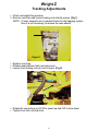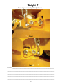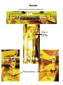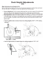
1
2007 Service Handbook “WHAT IT MEANS TO RIDE WRIGHT” Table of Contents Forms Warranty Claim Form Warranty Period Chart Pre-Delivery Mower Service Parts Order Issues (PFD) Service Bulletins Bulletin # 54 – Hydro Hose Application Chart Bulletin # 55 – Removing Hydro Cooler Bulletin # 56 – Adding Muffler Heat Shield Bulletin # 57 – Flat Rate Guide Bulletin # 58 – Re-routing Z Hydraulic Hose Bulletin # 59 – Mower Deck Lift upgrade Bulletin # 60 – Front Caster Part Number Information Bulletin # 61 – Cutting Deck Baffle System Bulletin # 62 – Deck Height Cog and Latch Kit Bulletin # 63 – 0069 pulley Service and Repair Neutral Adjust RTN Tracking Adjustments Z Checking and Adjusting Deck Alignment and Pitch Deck Alignment and Pitch Z Deck Alignment and Pitch Sentar Deck Alignment and Pitch WSES, WSR Deck Height Adjustments WSS Deck Height Adjustments WS, WV Deck Height Adjustments Velke Gear/Belt Drive Cutting Deck Baffle System Cutting Deck Baffle System w/o Pre-Punched Holes Electrical Troubleshooting Clutch Installation Clutch Evaluation Clutch Troubleshooting Spring compression tool Hydro Pump Hydro Pump Troubleshooting Deck Lift Improvement Kit 1 2 3 4 6 7 8 10 16 21 24 27 28 29 30 31 33 34 35 36 37 38 39 40 42 43 44 45 46 47 48 49 50 51 52 53 2007 Service Handbook Forms 1 Instructions CLAIM # 1. Verify that the part is covered by the warranty and that it is a valid claim. (See the original warranty statement and WMI Warranty Policy and Procedures.) 2. Verify that the mower is registered. Contact your Wright Distributor if you have questions regarding a mower registration. Only registered mowers are eligible for warranty. 3. Completely fill out this form, including Owner and Dealer signatures. Note: Claims are not valid without signatures, model and serial numbers. 4. Give gold copy of this form to customer; dealer keeps pink copy. 5. Submit the remaining copies of this claim to your distributor within 30 days of the repair. 6. Please contact your distributor if you have any questions regarding this claim. Warranty Request This is a: (check one) Repair part warranty request Whole goods warranty request Model Number: ______________ Date Sold:________________________ Serial Number: ______________ Date Brought in for Repair:____________ Hour Meter Reading:___________ Date of Repair:_____________________ Dealer Information Customer / Owner Information Owner's Name: _________________________________ Dealer's Name:________________________________ Company (if appl.):________________________________ Address: Address: ___________________________________ City/State/Zip: _________________________________ City/State/Zip: ___________________________________ Contact Name:_________________________________ Contact Name: ___________________________________ Phone: ( ) ________________________________ Phone: ( ) _________________________________ Fax: ( ) ________________________________ Fax: ( ) _________________________________ Email: ______________________________________ Email: ________________________________________ Owner signature Date _________________________________ Distributor Name:_______________________________ Dealer signature Date What part failed or caused the failure: Part Number:____________________Description:___________________________________________________ Describe the failure and correction performed:______________________________________________________ _________________________________________________________________________________________________________________________ _________________________________________________________________________________________________________________________ _______________________________________________________________________________________________________ Shaded Area for WMI Only QTY PARTS USED FOR REPAIR DESCRIPTION PART NUMBER / / / / Date Request Received Date Request Processed $ Registered Labor Rate hrs. Labor Hours Approved $ Labor Credit Approved $ Parts Credit Approved $ Total Credit Approved / / Date Credited Distributor LABOR REQUESTED # $________________________ X __________ . _________ = $ _____________________ LABOR RATE HOURS TENTHS WMI Credit Memo Number LABOR REQUESTED Copies to: White - Wright Mfg. Inc. z Yellow - Distributor z Pink - Dealer z Gold - Owner \\Server01\company\Marketing\Pagemaker\Product Specific Documents\Stander\Stander Warranty.p65; revised 6/19/01 2 Warranty Period Changes 4/01/05 Retail 3/17/03 Retail 3/01/02 Retail All previous sale and later sale and later sale and later General 2 year P&L 1P&L +1 Part 2 year P&L 2 year P&L Clutch 2 year P&L 1P&L +1 Part 1P&L +1 Part 1P&L +1 Part Spindle 2 year P&L 1P&L + 2 Part 1P&L +1 Part 1P&L +1 Part Pump 2 year P&L 2 year P&L 2 year P&L 2 year P&L Wheel Motor 2 year P&L 2 year P&L 2 P&L +2 Part 2 P&L +2 Part Deck 2 year P&L 1P&L +2 Part LL - 2 yr P&L LL - 2 yr P&L Engine Deck 2 year P&L 1P&L +2 Part LL - 2 yr P&L LL - 2 yr P&L Frame 2 year P&L 1P&L +2 Part LL - 2 yr P&L LL - 2 yr P&L Upright 2 year P&L 1P&L +2 Part LL - 2 yr P&L LL - 2 yr P&L Hydraulic Hose 2 year P&L Excluded Excluded Excluded Battery 90 day 90 day 90 day 90 day Belt 90 day Excluded Excluded Excluded * Applicable warranty based solely on original retail purchase of mower * Refer to applicable warranty document for clarification and exclusions * Warranty not transferable * Cracked weldments must be pre-approved LL = Limited Lifetime P&L = Parts and Labor 3 PRE-DELIVERY SERVICE OF MOWER BY DEALER The Wright Mower is shipped completely assembled and has been adjusted and tested at the factory. However, due to the jostling of the shipping process and the delivery time lapse, the following items need to be repeated again before starting the mower. After you have uncrated the mower, follow these procedures in the order indicated: x Remove spark plug wire from spark plug(s). x Inspect the mower for any damage, unusual conditions or missing parts. x Inspect the mower for all of its decals, especially the warning decals. There should be one blade warning decal on each side of the deck, the “shield missing” decal under the blade belt cover, and the dash decal. x Check to ensure belt guard is in place before operation. x Check (and fill if necessary) engine oil level according to the engine manufacturer’s recommendation. x Check (and fill if necessary) hydraulic fluid level. Use fully SYNTHETIC oil: Mobil-1 15W-50. x Check tire pressures. Adjust to recommended pressure. It should be even on both sides but the recommended pressures are generally different for the front and rear tires. x Remove the blade belt cover and check (adjust if necessary) all belt tensions according to specifications in Owners Manual. DO NOT OVERTIGHTEN. x Rotate the blade pulleys slightly to see if they all turn together. (Note: Clutch Brake will create some resistance.) x Lubricate all appropriate moving parts x Reinstall the blade belt cover. x Remove battery (if electric start version) from machine and fully charge (if necessary) in an open, well-ventilated area according to the recommendations of the battery charger manual. The battery is 12 volts. After fully charged, install on mower and attach battery cables, positive first (from starter motor) and negative last (from ground). x Fill fuel tank with regular unleaded gasoline. Open fuel valve located between fuel tank and engine. x DO NOT START THE ENGINE AT THIS TIME. FOLLOW THE NEXT PROCEDURE BEFORE STARTING. The hydraulic system MUST be checked for proper operation before allowing wheels to operate on the ground. x Set the rear of the machine on jack stands or blocks to raise rear wheels off the ground two or three inches and check to be sure that the mower will not fall off the supports you devise. The stand(s) must be able to secure the mower from rolling off or away during the next procedures. Check under the mower deck for any debris or unusual conditions. x With hand controls and speed control in the neutral position, apply the parking brake. x Open the manual bypass valve on top of each pump a half-of-a-turn counterclockwise. x Reattach spark plug wires to spark plugs. x Before starting the engine, be ready to stop it if the wheels begin to turn with the brake on. (If this happens, check that the manual bypass valve on top of each motor are open at least a half-of-aturn counterclockwise.) x Start the engine according to the engine manufacturer’s recommendation. Let the engine run at low RPM for several minutes to get the hydraulic fluid circulating through the pumps, etc. Release the parking brake. Now gradually close the manual bypass valve on top of each pump one at a time, and see if the wheels start to move. If the wheels move when the hand controls are in neutral position, adjust the neutral adjustment allen screw located on each pump until they stop (use the neutral adjust knob for older mowers). The manual bypass valve on top of each pump should now be firmly closed. Now try moving the hand control levers, one at a time, to make the wheels move in forward and backward rotation. Check to see if the wheels move forward and backward according to position of the levers. If not, service the hand control system. If the wheels stop when the hand controls are in the neutral position the parking brake should now be applied. Now check 4 x x x x x x x if the parking brake locking system (if applicable) prevents the unit from being driven while engaged. If not, service the parking brake locking system. Before testing the blade clutch/brake operation, make sure the area is clear and there is nothing vulnerable to possible thrown objects from under the mower. No one should be near the mower deck or in its line of discharge at this or at any time. The discharge chute deflector should be in the down position. Move the engine throttle control to its highest RPM speed setting. Turn on the blade clutch switch. Run blades for a minute or so. Try engaging and disengaging the blades a few times about 10 seconds apart. If the blades do not start and stop in a few seconds each time, service the blade brake system. With the blades on, now try disengaging the OPC switch to test the Operator Presence Control switch (OPC). The engine should die and the blades should stop in several seconds. If not, service the OPC system. Try this a couple of times. Disengage the blades, shut off the engine and remove the mower from the stand(s). Drive the mower around on a level parking lot. It is recommended that the slower setting of the Speed Adjustment be used. (See further in this manual for information on Speed Adjustment.) Check that the mower drives in a straight line when both hand controls are at the full speed position. If not, see further in this manual for information on tracking adjustment. As you drive the mower, listen for any unusual noises and test for irregular operation and adjust or service as necessary. Next, go over the safety information and operating procedures in this manual with the customer. Instruct the customer in proper operation and observe the customer during their initial operation on a level parking lot. Make sure the customer is familiar and comfortable with the basic operation and use of the mower. Dealer: Register the mower online. If unable to use the online registration process then follow the instructions on the Product Registration Form and have the customer fill out his part of the form. After the Product Registration Form is filled out and signed by the customer and a representative from your dealership, please mail or fax it immediately (within 30 days from date of retail purchase) to your Wright Commercial Products Distributor according to the directions on the Form. Then give the customer his copy of the registration form and then keep your copy and mail the remaining copies of the form to your Wright Manufacturing Products Distributor. The limited warranty is not valid unless the mower is registered and all of the above steps are taken. Remember, the purchaser is both your and our customer and his satisfaction is very important. Thank you for supporting our products. The mower is now ready for delivery to your customer. 5 PFD Some parts have been revised but still are using same part #. ¾WS Upright Frame – Two styles, same part # 93420038 ¾52” Sentar Deck – Need serial # + photo ¾61” Sentar 1 & 2 – Need serial # ¾WS Cockpit/tractor frame – Need serial # 6 2007 Service Handbook Service Bulletins 7 Bulletin # 054 2 Pages February 9, 2006 Hydro Hose Application Chart INFORMATION ONLY Subject: The following page is a chart to be used as a resource for determining the proper high pressure hydraulic hose and part number for the various possible current applications Units Affected: ALL current Situation: None – information only The Fix: None – information only Claim Procedure: None – information only 8 9 48" 43" 20" 21" 21" 34" 21" 23" 23" 27" 27" 32" 32" 33410051 33410052 33410057 33410061 33410062 33410063 33410064 33410065 33410066 33410067 X X Obsolete Obsolete Obsolete Obsolete Obsolete Obsolete Obsolete X 27" X 28-1/4" ĺ ĺ ĺ ĺ ĺ ĺ ĺ Hose cutlength 33410004 33410005 33410010 33410011 33410015 33410031 33410032 33410012 33410014 33410037 33410038 33410050 Hydro hose part # X ĺ ĺ ĺ ĺ ĺ ĺ ĺ Crimp Fitting Motor X X X X X X X X X X X X X X w w/o w w/o w w/o w w/o Straight JIC Short 90 JIC 90 FF Straight FF Long 90 JIC 35410041 Fitting Incl FF Nipple Incl. 35410041 Fitting Incl FF Nipple/ JIC 90 Incl 35410041 Fitting Incl FF Nipple/ JIC 90 Incl All All 35410041 Fitting Incl 28215 & Up FF Nipple/ JIC 90 Incl -Velke Mower =S/N pre 28215 Left Side Right Side 35410041 Fitting Incl FF Nipple Incl. Comments FF = Flat-Face fitting w/ o-ring Straight FF Straight JIC Short 90 JIC Straight FF 90 FF Straight JIC 45 JIC Long 90 JIC Short 90 JIC Straight JIC 90 FF Straight FF Straight FF Straight FF Short 90 FF Straight JIC Short 90 JIC Straight FF Short 90 FF Short 90 JIC Long 90 JIC Straight FF Straight FF Straight JIC 90 FF Pump With Hoops Use 33410062 / With-Out Hoops Use 33410063 Pump With Hoops Use 33410064 / With-Out Hoops Use 33410065 Pump With Hoops Use 33410051 / With-Out Hoops Use 33410052 Pump With Hoops Use 33410051 / With-Out Hoops Use 33410052 Pump With Hoops Use 33410066 / With-Out Hoops Use 33410067 Pump With Hoops Use 33410066 / With-Out Hoops Use 33410067 Pump With Hoops Use 33410066 / With-Out Hoops Use 33410067 Hoops Crimp Fitting Pump High Pressure Hose Application Chart Sen t a r 1-S /N p 19 72 rior to Sent 9 ar 2 S /N 1 9 an 729 Sent d higher a r 3 - S/N 26 and high 980 er Se n t a r Sp ort Larg e Sta nde r 4 8 ,52 ,6 1 Sma ll S t a n der 3 6,4 2 Stan der R H WSS Sta n d e r S/N 3 2,3 6 2 628 ,4 2 8 Ve a n l k e Mow d highe r er Q Leve uad r Velk e Mo we r P i stol Grip Bulletin # 055 6 Pages May 10, 2006 REMOVING HYDRAULIC OIL COOLER ON SPORT and RH MOWERS *** PRODUCT RECALL *** Subject: Units Affected: Situation: Removal of hydraulic oil coolers on all Sport and RH mowers All Sport and RH mowers with a serial number from 24188 through 30058 that have the hydraulic oil cooler. Mowers beyond this serial number range have been produced to updated standards according to new design. It has been determined that the hydraulic oil cooler for these mowers is unnecessary for the hydraulic system and that it should be removed. All mower registrations must be completed and entered into the Wright online registration system and communicated to Wright Manufacturing within 20 days of receipt of this letter. Failure to do this exposes the Dealer to the liability of consequential damages should a problem develop with the mower related to the items in this bulletin. This product recall requires that all affected mowers have the hydraulic oil cooler removed as quickly as possible and no later than 40 days from the date of this bulletin. In cases where the mower has been retailed, the Dealer should make very effort to accommodate those mowers into their schedule at the earliest possible date. We will be contacting all currently registered mower owners to inform them of the need for this service but request that each Distributor/Dealer contact their customers as well. Additionally, we may not have registration for all retailed mowers which makes it impossible for us to contact the consumer. In the event that engine damage occurs due to the consumer not having knowledge of this recall due to non-registration, the 10 Bulletin # 055 6 Pages May 10, 2006 liability for consequential damage will be on the selling Dealer. This work is to be done in conjunction with Bulletin #056 The Fix: Using the attached instructions: 1) Remove the hydraulic oil cooler from all affected mowers 2) ONLY IF MOWER RETAILED - Remove the engine shroud and clean the engine cooling area and fins with compressed air For units that have been retailed, contact the end-user to have these services performed. Units that have been retailed but not registered must be registered immediately. *** All affected mowers need to have this update performed. No affected mower should be retailed without this service being performed *** The engine manufacturer recommends cleaning the dust, dirt and debris from cylinder and cylinder head cooling fins every 100 hours or more often under dusty conditions. Grass clogged cylinder heads and cooling fins can contribute to engine overheating and we strongly recommend this service item be done frequently. Please take this opportunity to perform this necessary maintenance service. The plastic engine shroud must be removed to perform this service. Claim Procedure: 0.6 hour of labor allowed. An additional 0.4 is allowed for cleaning the engine cooling fins if the unit has been retailed. Complete the attached “Quick-Claim-Form” and submit within 15 days of the date of repair. Work must be performed at the same time as Bulletin #056 and should be claimed on the same claim form. 11 Bulletin # 055 6 Pages May 10, 2006 Hydraulic Oil Cooler Removal and Engine cooling area cleaning Instructions Sentar Sport and Rapid Height (RH) Stander mowers only 1. Remove cooler cover by removing truss-head screw (Fig 1, A). Fig. 1 A 2. Remove truss-head screws attaching front (Fig. 2, A) cooler bracket to engine guard and 2 nuts attaching rear bracket to engine guard. (Fig. 2, B) 3. Lift cooler from engine, reinstall and tighten acorn nuts 4. Loosen hose clamp (Fig.2, hose 1) Fig. 2 2 A B B 1 5. Remove knee pad. CAUTION: There are several cut wire ties behind knee pad that can cut you. 12 Bulletin # 055 6 Pages May 10, 2006 NOTE: The two photos below (Fig’s 3 & 4) are using the numbers 1 & 2 to indicate which hose from Fig 3 will correspond with the hose from Fig 4. 6. Cut wire ties holding feed and return line together (see arrow in Fig 4) 7. Crimp hose at hydro tank return (Fig 4 hose 1) NOTE: Crimping tool would be ideal, if you do not have, use care not to crush hose. 8. Hose 2 needs to be cut from the return line tee. Use care not to cut yourself and not to damage the tee. NOTE: Oil may spill Fig 3 Fig 4 2 1 Return Feed 2 1 9. Remove line 1 from cooler (Fig.3) and cut 5” from end NOTE: Some oil may spill 10. Connect hose to return line tee (Fig 5 hose 1) 1 11. Check fluid level and fill as needed. Fig 5 12. Check for leaks and re-install knee pad. 13. FOR RETAILED MOWERS ONLY: Return Remove engine shroud/fan housing and thoroughly remove all grass and debris from engine and fan using compressed air. This Feed bulletin provides an additional 0.4 hours of labor for this step to be performed on retailed mowers. * This is an engine manufacturer recommended service and should be done regularly according to the engine manufacturer recommendations 13 Bulletin # 055 6 Pages May 10, 2006 Below is a copy of the letter being sent to each currently registered owner of the affected mowers. Keep in mind the registration information we have may not be accurate or current so do not assume this letter will make it to the registered owner – please also contact them yourself. ___________________________________________________________________________________ PRODUCT RECALL Models affected within a limited serial number range: • Sentar Sport • Stander RH May 15, 2006 We are pleased you have chosen to own a Wright product and trust your experience has been pleasant thus far. Wright Commercial Products is committed to continuous improvement. Consistent with that commitment, we are recalling specific mowers for the following repairs: • • The hydraulic oil cooler located on the top of the engine is unnecessary and should be removed. The engine cooling fins will be cleaned out at the time of this service. o Mowers with a serial number from 24188 through 30058 and a model number beginning with either WSES or WSR A newly designed muffler heat shield needs to be installed o Mowers with a serial number from 24188 through 33155 and a model number beginning with either WSES or WSR Choosing to not have this product recall work performed on your mower within the prescribed time frame could eventually result in severe overheating damage to your engine and will VOID THE WARRANTY on your engine making any repairs to or replacement of the engine your responsibility. The product recall work must be performed at your local Authorized Wright Dealer and there will be no charge to you for these services. Please schedule to have this work performed as quickly as possible and within no more than 20 days from receipt of this letter. If needed, you can find the Dealer of your choice at www.wrightmfg.com and choose the Dealer locator option. As always, we’re committed to making your experience with Wright products as productive and pleasant as possible. The Wright Commercial Products Team 14 Bulletin # 055 6 Pages May 10, 2006 Wright Warranty Quick-Claim-Form - Bulletins 055 and 056 only 1 mower per form Dealer Name: _______________________________ Dealer Location/City: ___________________ Distributor: _____________________________ Date of repair: ___________________________ Mower Serial Number: _______________ Registered: Ƒ Yes Ƒ No (if not then attach registration if retailed) Mower Model: Ƒ WSES36 Ƒ WSES48 Ƒ WSES52 Ƒ WSR36 Ƒ WSR48 Ƒ WSR52 Engine Serial Number (Full): ______________________ (Claim will be rejected without this information) Choose only 1 of the 4 scenarios below that most accurately represents the situation with this mower Ƒ Scenario #1 * Mower not retailed – needs heat shield only Time allowed for this scenario: .6 hours - Serial range is 24188 - 33155 Ƒ Scenario #2 * Mower retailed – needs heat shield and engine cooling fins cleaned Time allowed for this scenario: 1.0 hours - Serial range is 24188 - 33155 Ƒ Scenario #3 * Mower not retailed – needs hydraulic oil cooler removed and heat shield Time allowed for this scenario: 1.2 hours - Serial range is 24188 - 30058 Ƒ Scenario #4 * Mower retailed – needs hydraulic oil cooler removed, engine cooling fins cleaned and heat shield Time allowed for this scenario: 1.6 hours - Serial range is 24188 - 30058 FOR ALL SCENARIOS – if applicable Condition of Engine Cooling Fins (if applicable): Ƒ No notable grass/debris collection Ƒ Mostly clean Ƒ Mostly clogged Ƒ Very Badly Clogged _______________________________________________________________________________ Make additional copies if needed. Fax or Mail completed forms to your Distributor 15 Bulletin # 056 5 Pages May 10, 2006 ADDING MUFFLER HEAT SHIELD ON SPORT & RH MOWERS *** PRODUCT RECALL *** Subject: Units Affected: Situation: Adding the muffler heat shield on all Sport and RH mowers NEW PART # 91410026 – includes heat shield and gaskets All Sport and RH mowers with a serial number from 24188 through 33155. You may find that some of the serial numbers in this range have had the update performed prior to your receiving the mower. It has been determined that a muffler heat shield needs to be added to the affected mowers listed above. This is an important recall. All mower registrations must be completed and entered into the Wright online registration system and communicated to Wright Manufacturing within 20 days of receipt of this letter. Failure to do this exposes the Dealer to the liability of consequential damages should a problem develop with the mower related to the items in this bulletin. This product recall requires that all affected mowers have the muffler heat shield installed as quickly as possible, and no later than 40 days from the date of this bulletin. In cases where the mower has been retailed, the Dealer should make very effort to accommodate those mowers into their schedule at the earliest possible date. We will be contacting all currently registered mower owners to inform them of the need for this service but request that each Distributor/Dealer contact their customers as well. Additionally, we may not have registration for all retailed mowers which makes it impossible for us to contact the consumer. In the event that engine damage occurs due to the consumer not 16 Bulletin # 056 5 Pages May 10, 2006 having knowledge of this recall due to non-registration, the liability for consequential damage will be on the selling Dealer. This work is to be done in conjunction with Bulletin #055 The Fix: Using the attached instructions, install the muffler heat shield on all affected mowers. For units that have been retailed, contact the end-user to have this service performed. Units that have been retailed but not registered must be registered immediately. *** All affected mowers need to have this update performed. No affected mower should be retailed without this service being performed. Claim Procedure: 0.6 hour of labor allowed. Complete the “Quick-Claim-Form” in Bulletin #055 and submit within 15 days of the date of repair. Work must be done at the same time as Bulletin #055 and should be claimed on the same claim form. 17 Bulletin # 056 5 Pages May 10, 2006 Installation Instructions for Replacement Heat Shield WMI part number: 91410026 Step One: Remove the four nuts on the exhaust ports with a 12mm socket and the upper mounting bracket nut and bolt using two 1/2-inch wrenches Step Two: After removing muffler from engine, remove the heat shield if it is still attached to the muffler can. This can be done using Tin-Snips (as shown below). Be careful not to damage or puncture the muffler can in the removal process. 18 Bulletin # 056 5 Pages May 10, 2006 Step Three: Install the replacement heat shield by directing the exhaust port mount under the muffler header bracket and aligning the upper mounting bracket through the oblong hole in the shield. Step Four: Thoroughly remove old gasket material and clean affected areas. Using new exhaust gaskets (included with heat shield), remount the muffler can with exhaust studs going through the heat shield. Align the upper mounting bracket of the heat shield such that the muffler tailpipe is centered on the side and not touching the heat shield. 19 Bulletin # 056 5 Pages May 10, 2006 Below is a copy of the letter being sent to each currently registered owner of the affected mowers. Keep in mind the registration information we have may not be accurate or current so do not assume this letter will make it to the registered owner – please also contact them yourself. ____________________________________________________________________________________ PRODUCT RECALL Models affected within a limited serial number range: • Sentar Sport • Stander RH May 15, 2006 We are pleased you have chosen to own a Wright product and trust your experience has been pleasant thus far. Wright Commercial Products is committed to continuous improvement. Consistent with that commitment, we are recalling specific mowers for the following repairs: • • The hydraulic oil cooler located on the top of the engine is unnecessary and should be removed. The engine cooling fins will be cleaned out at the time of this service. o Mowers with a serial number from 24188 through 30058 and a model number beginning with either WSES or WSR A newly designed muffler heat shield needs to be installed o Mowers with a serial number from 24188 through 33155 and a model number beginning with either WSES or WSR Choosing to not have this product recall work performed on your mower within the prescribed time frame could eventually result in severe overheating damage to your engine and will VOID THE WARRANTY on your engine making any repairs to or replacement of the engine your responsibility. The product recall work must be performed at your local Authorized Wright Dealer and there will be no charge to you for these services. Please schedule to have this work performed as quickly as possible and within no more than 20 days from receipt of this letter. If needed, you can find the Dealer of your choice at www.wrightmfg.com and choose the Dealer locator option. As always, we’re committed to making your experience with Wright products as productive and pleasant as possible. The Wright Commercial Products Team 20 Bulletin # 057 1 Page May 10, 2006 Flat Rate Guide Subject: Moving to a Flat Rate system for determining allowed labor times. Also providing a parts cost reimbursement premium to allow for an additional 15% above Dealer cost on warranty repairs parts. Units Affected: All Situation: See above The Fix: For all work with a repair date of May 15, 2006 or later use the guide to determine times allowed for specific repair work performed. The guide is not exhaustive and will continue to develop as time goes on. The guide may be accessed online at http://purchase.wrightmfg.com under “Service Area” using your unique Dealer login. Contact your Distributor if you do not have login information. Additionally, Wright will begin paying a parts cost reimbursement premium on all claims which should equal roughly 15% above Dealer cost. This is designed to help offset the costs related to handling warranty claims and their parts. Claim Procedure: When warranty repairs are performed, use the Flat Rate Guide for determining labor times. 21 4600X Wedgewood Blvd., Frederick, MD 21703 FLAT RATE SCHEDULE INTRODUCTION This Flat Rate Manual is designed to be used as a guide for labor cost estimates of repair work. 1. What do the Flat Rate times mean? ĺ Each description has a table listing showing the flat rate times for all applicable models. The flat rate times are given in multiples of 1 /10 hour. Example: .1 = 6 minutes .2 = 12 minutes .3 = 18 minutes .4 = 24 minutes .5 = 30 minutes .6 = 36 minutes .7 = 42 minutes .8 = 48 minutes .9 = 54 minutes 1 = 60 minutes 1.2 = 66 minutes ĺ The flat rate manual times have been designed to generally include all associated work. 2. How are the Flat Rate times determined? Flat rate times are determined with the following conditions as a standard: ĺ The common tools, special tools and all other equipment needed for repairs are on hand and so placed as to be readily available for use. The times are not based on the use of any air tools. ĺ The flat rate times have been developed, over time, from an average of work performed by skilled mechanics. 3. Calculating the flat rate time when more than two kinds of work are performed at a time on the same mower. ĺ If the jobs are independent of one another, just add the times together. ĺ If the jobs are related to one another or overlap, take either the longest time or the time for the part which has been removed or replaced last. 301.360.9810 www.wrightmfg.com 22 Fax 301.360.9820 FLAT RATE GUIDE Labor Allowed in Hours - labor allowed subject to applicable warranty Work Performed-R&R Stander Sentar Velke Mower Sport / RH Clutch 0.8 1.2 0.8 0.8 Deck Belt Hydro Belt Hydro Hose - High pressure Cutting deck Spindle - each Throttle Cable 0.5 0.5 0.7 2 0.5 0.5 0.3 0.6 0.7 2.3 0.5 0.5 0.3 0.5 0.7 2 0.5 0.5 0.3 0.5 0.7 2 0.5 0.5 Wheel Motor - each 1 1 1 1 Hydro Pump - each 1 1.5 1 1 Fuel Tank Solenoid Ignition Switch Blade switch - PTO 0.5 0.5 0.5 0.5 0.5 0.7 0.7 0.5 0.5 0.5 0.5 0.5 0.5 0.5 0.5 0.5 Upright 1.3 1.6 1.3 1.3 - - - - 0.4 0.5 0.4 - 0.4 0.5 0.4 - 0.7 0.5 0.7 0.5 0.7 0.5 0.7 0.5 Engine and related Relay Battery Stand Wheel Hub Pulley / Idler 23 Notes Return Parts Sentar: may have to separate clutch or shift engine to remove YES if mutiples then .5 each YES newer models are side specific-check IPL newer models are side specific-check IPL includes diagnostic time includes diagnostic time includes diagnostic time Velke Mower is for pistol grip models not covered-see engine manufacturer includes diagnostic time broken studs not covered under warranty YES YES YES Bulletin # 058 3 Pages June 29, 2006 Re-routing Z hydraulic hose Subject: Units Affected: Re-routing hydraulic hose part number 33410075 All Mid-Mount Z mowers with a serial number from 30200 through 34006 Situation: The hydraulic hose is routed below the hydraulic tank and can come in contact with the deck belt. If this happens, the belt can wear through the hose and cause the hose to leak The Fix: Re-route the hose from the hanging position to up between the hydraulic tank and mower frame as pictured below. The hose fittings on the pump will need to be re-oriented to accommodate this change as pictured below. This work should be performed as quickly as possible on each affected mower. Do not wait until the hose fails. Claim Procedure: 0.4 hours allowed if work performed within the normal warranty period of the mower. 24 Bulletin # 058 3 Pages June 29, 2006 Bottom view of old routing configuration: Fig. 1 Hose routed horizontally below the hydro tank Top view of new routing configuration: Fig. 2 B A Hose looped up between the hydro tank and the frame (A) and the pump fittings are re-oriented at an angle towards the bottom of the hydro tank to eliminate the possibility of hose binding (B) 25 Bulletin # 058 3 Pages June 29, 2006 Bottom view of new routing configuration: Fig. 3 26 Bulletin # 059 1 Page June 29, 2006 Sport / RH mower deck-lift update kit Subject: Units Affected: Providing a kit to repair malfunctioning deck lift systems • Part # 95460006 - for mower serial numbers from 26077 through 27077 • Part # 95460005 – for mower serial numbers from 27078 through 33614 All Sport and Stander RH models with serial numbers up to 33614 Situation: Some Sport and RH (predominantly 52”) model mowers have experienced premature wear in the deck-lift system. This wear can affect deck leveling, deck pitch and, potentially, quality of cut. The Fix: Only if a particular mower experiences premature wear in the deck-lift system, install this kit. Installation instructions come with the kit. Claim Procedure: 1.0 hour of labor allowed if work performed within the normal warranty period of the mower. Complete a Wright warranty claim form 27 Bulletin # 060 1 Page August 29, 2006 Front caster part number information ** Information only ** Subject Providing part number information for front casters – now offering flat-free style (non-pneumatic) tires in addition to offering pneumatic tires for front casters Units Affected: All Situation: All mowers currently produced are being assembled with the flat-free style tires on the front casters. Both the flat free style and pneumatic tires will be available for purchase through our parts department. The chart below outlines the various options and part numbers. Currently the pricing for the flat-free style assembly is the same as the pneumatic The Fix: None – information only Claim Procedure: None – information only Tire/Wheel Assembly Stander / Sport / RH Velke Mower Sentar & Mid-Mount 48" and 52" Mid-Mount 61" only Pneumatic 72460002 72460003 72460004 n/a Flat-Free 72460012 72460013 72460014 72460009 28 Bulletin # 061 1 Page September 7, 2006 Cutting Deck Baffle-System Option Subject New optional deck baffle system Units Affected: All three bladed machines Situation: Consistent with our commitment to continuous improvement, an optional baffling system has been developed for purchase as an upgrade to cutting decks. This system is designed to further improve cut quality, air flow and discharge. This is an optional upgrade with the exception of Mid-Mount Z mowers - each of these mowers will have the opportunity to obtain the upgrade free of charge (parts only) The Fix: The kits will be available beginning September 18, 2006. Order as needed using the following information. Current MSRP for each kit is $95.00 Mid-Mount Z mowers: 48” deck – 95430006 52” deck – 95440007 61” deck – 95450006 All other mower models: 48” deck – 95430005 52” deck – 95440006 61” deck – 95450005 Claim Procedure: For Mid-Mount Z mowers: Purchase and install the kit. File warranty claim for parts only For all other models: None - optional upgrade 29 Bulletin # 062 1 Page September 29, 2006 Sport & RH Deck Height Cog and Latch Kit Subject Units Affected: Updated deck height cog and latch kit KIT PART NUMBER: 95460008 (includes items pictured below) All Sport and RH units with a serial number of 35929 or lower Situation: An updated deck height cog and latch kit has been developed for units that have experienced the deck height latch “ratcheting” up into a higher cutting height position while mowing on uneven ground. This kit insures that the selected cutting height is maintained The Fix: As units experience difficulty maintaining the selected cutting height, order part number 95460008 and install the kit according to the instructions included with the kit Claim Procedure: 0.5 hours of labor allowed if work performed within the normal warranty period of the mower 30 Bulletin # 063 2 Pages October 5, 2006 Pulley Parts information Subject Units Affected: Situation: The 71460069 pulley is being replaced with a new pulley Stander 42” – serial 26288 through 35903 Sentar 52” & 61” – serial 26988 through 35988 Z 52” & 61” – serial 30200 through 36009 Pulley 71460069 is being replaced with part number 71460098. 71460098 requires a bore adapter and additional hardware for proper installation, fit and function Part number 71460069 is being superseded by kit part number 71460106 (for Sentar and Z applications). When an order is received for 71460069, it will be filled with 71460106. 71460106 is a kit that includes: • 71460098 – pulley • 22420007 – bore adapter for certain Sentar and Z mowers • 13990038 - washer Î If replacing the pulley on a 42” Stander, see below for individual component part numbers – a pulley kit is not available for this mower Additional parts information is listed below. The Fix: Claim Procedure: This is not a recall - use the information provided to order the correct parts only as needed None – this is for informational purposes only 31 Bulletin # 063 2 Pages October 5, 2006 This information applies to mower models that currently are using the 71460069 pulley 1 1 2 1 2 3 4 3 6 4 2 2 2 3 2 5 5 7 WS 42 WSE 52, 61 1 2 3 4 5 6 7 * * * * * Nut, 3/8 – 16 Washer, Flat 3/8x1-½ Idler Pulley 6” Bore Adaptor WSE, WZ Bolt, 3/8 – 16 x 2-¼ Bore Adaptor WS 42 Bolt, 3/8 – 16 x 2-¾ WZ 52, 61 12990031 13990038 71460098 22420007 11990068 22420006 11990006 Items with an asterisk (*) are required for the initial upgrade to the 71460098 pulley. 32 2007 Service Handbook Service and Repair 33 Neutral adjust on RTN models x Raise and secure machine x Using ¼” Allen, loosen (1) and move (2) up or down, until tire movement stops 1 2 x Tighten and move controls forward and reverse to check. NOTES:_____________________________________________________ ____________________________________________________________ ____________________________________________________________ ____________________________________________________________ ____________________________________________________________ ____________________________________________________________ ____________________________________________________________ ____________________________________________________________ 34 Wright Z Tracking Adjustments ¾Check and adjust tire pressure ¾ Remove rear tires and loosen locking nuts at both pumps. (Fig 1) NOTE: If motor supports are in rearward holes for the bagging system then it is not necessary to remove the rear wheels. Figure 1 ¾Replace rear tires ¾Release seat platform latch and raise seat. ¾Loosen front locking nuts at control levers. (Fig 2) Figure 2 ¾Rotate the connecting rod CCW to speed up and CW to slow down. ¾Tighten front lock nut and drive 35 CHECKING AND ADJUSTING DECK ALIGNMENT AND PITCH Alignment ¾Check and adjust tire pressure ¾Set deck to 3” ¾Measure top of deck to floor. a) Trim side front___ Rear___ b) Discharge side front____ Rear____ ¾Both front measurements should be the same. ¾Rear measurements should also be the same but 1/8-1/4” higher than front measurement. ¾Make necessary adjustments to level deck. Pitch ¾Set deck to 3” ¾Align blade tip to face forward. ¾On Standers, Sports and Sentar the operator or equivalent to operators weight must be on the foot platform or seat while measurements are taken. ¾Measure front blade tip to floor ¾Measure back blade tip to floor ¾Perform these steps on both trim side and discharge side blades. ¾Back blade tip should be 1/8” – 1/4" higher than the front blade tip. ¾Make necessary adjustments to ensure forward pitch. NOTES:_____________________________________________________ ____________________________________________________________ ____________________________________________________________ ____________________________________________________________ ____________________________________________________________ ____________________________________________________________ ____________________________________________________________ ____________________________________________________________ 36 Wright Z ¾Deck alignment and pitch adjustments Front Rear NOTES:_____________________________________________________ ____________________________________________________________ ____________________________________________________________ ____________________________________________________________ ____________________________________________________________ 37 Sentar ¾Deck alignment and pitch adjustments 16 ½” Raise or lower one side Pitch adjustments Rear Front 38 WSES, WSR ¾Alignment and pitch are somewhat limited. NOTES:_____________________________________________________ ____________________________________________________________ ____________________________________________________________ ____________________________________________________________ ____________________________________________________________ ____________________________________________________________ ____________________________________________________________ ____________________________________________________________ 39 Deck Height Adjustments WSS Blade Adjustments and Height-of-Cut Before Adjusting the Height-of-Cut be sure of proper air pressure in all four tires and check for even tire wear. The height-of-cut can be adjusted the following ways: ¾Coarse Adjustment: For the coarse adjustment the rear motor support (1) and the front caster arm (2) should be adjusted at the same time. Adjust the rear wheel motor supports equally in one of the three settings up or down 0.75" each in a 1.5" total range. ¾Fine Adjustment: Adjust the blades equally in five settings up or down 0.25" each in a 1.25" total range. The shims on the blade bolts are moved from under the spindle to the top of the spindle. If possible, leave at least one shim at the top and the bottom of the spindle shaft. Use the middle holes in tractor frame for cutting heights of 2.5" - 3.75", factory setting 3”. 2 1 Use the highest holes in tractor frame for cutting heights of 1.75" - 3.0". 40 Use the lowest holes in tractor frame for cutting heights of 3.25" - 4.5". . NOTES:_____________________________________________________ ____________________________________________________________ ____________________________________________________________ ____________________________________________________________ ____________________________________________________________ ____________________________________________________________ ____________________________________________________________ ____________________________________________________________ 41 Deck Height Adjustments WS, WV Hydro 1.75-3.0” 2.5-3.75” 3.25-4.5” 3” 42 Deck Height Adjustments Velke Gear/Belt Drive NOTES:_____________________________________________________ ____________________________________________________________ ____________________________________________________________ ____________________________________________________________ ____________________________________________________________ ____________________________________________________________ ____________________________________________________________ ____________________________________________________________ ____________________________________________________________ 43 Cutting Deck Baffle System Installation Instructions 1. Remove deck covers. 2. Raise and secure unit so cutter deck is accessible. 3. Mount baffle as shown in figures using hardware included. Note: *Some older units may not have holes pre-punched. See instructions for mounting and drilling holes. 4. Spin blades by hand to make sure blades will not hit baffle. Note: *If spindle is the type with 2 spacers between the blade and the spindle then one spacer needs to be removed. *Standers and Velkes must have all blade spacers installed. (5ea. Spindle) NOTES:_____________________________________________________ ____________________________________________________________ ____________________________________________________________ ____________________________________________________________ ____________________________________________________________ ____________________________________________________________ ____________________________________________________________ 44 Baffle installation with-out pre-punched holes in cutter deck Fig. 1 Fig. 2 1. 2. 3. 4. 5. Remove deck covers. Raise and secure unit so cutter deck is accessible. Remove blades and scrape all grass from the under side of the deck. Align discharge-side of baffle with front outside edge of deck, and clamp. (Fig. 1) Slide trim-side up tight against front of deck, and clamp. (Fig. 2) Note: * It may require two people to set and clamp baffle. * Install blades loosely and spin by hand to ensure there is no interference with the baffle. 6. Drill holes (4 or 5, depending on deck size) using a 3/8” drill bit. (Fig. 3) 7. Secure baffle to deck using hardware provided. 8. Tighten blade bolts and run to check for interference. Fig. 3 45 Electrical Troubleshooting Engine Does Not Crank Problem Possible Causes or Solution Battery Voltage Below 12 Volts Follow Charging System Troubleshooting Guide Certain machines require the Parking Brake to be set before starting, check linkages and switch. The controls must be in the neutral position before starting Inspect neutral interlock linkages and ensure that switch is being completely depressed Check switch continuity; should be continuous when engaged (depressed) Check for a blown fuse. If fuse is blown, check for short circuit and replace with 20A Fuse. Never use a circuit breaker style fuse. Disconnect, clean and reconnect electrical connections and ensure a good connection is made with all wires. Check for loose wires and connectors. Parking Brake Not Set Controls Not in Neutral Check Fuse on Purple Circuit Bad Elecrical Connection in Circuit Engine Cranks: Does Not Start Problem Gasoline Parking Brake Not Set Controls Not in Neutral Bad Elecrical Connection in Circuit Possible Causes or Solution Check fuel valve position Check for Varnished Gas and replace with fresh gasoline if needed Certain machines require the Parking Brake to be set before starting, check linkages and switch. The controls must be in the neutral position before starting Inspect neutral interlock linkages and ensure that switch is being completely depressed Check switch continuity; should be continuous when engaged (depressed) Disconnect, clean and reconnect electrical connections and ensure a good connection is made with all wires. Check for loose wires and connectors. Mower Starts: Does Not Charge Measure/Test: Possible Causes or Solution Check Battery Voltage Battery Voltage should be greater than 12 Volts, may need replacing if low voltage or old Fuse on Yellow Circuit Yellow Wire Connector on Key Switch Check Key Switch Bad Elecrical Connection in Circuit Check Stator Voltage from Engine while running Check for a blown fuse. If fuse is blown, check for short circuit and replace with 20A Fuse. Never use a circuit breaker style fuse. Inspect Yellow wire connection on Key Switch for good contact Key Switch Connectors A and B should have continuity in the "RUN" position Disconnect, clean and reconnect electrical connections and ensure a good connection is made with all wires. Check for loose wires and connectors. Engine voltage from Stator should be greater than 12 Volts when engine is at full throttle. Clutch Circuit Problems Problem Possible Causes or Solution Check Operator Presence Control (OPC) Switch; Black and Gray switches cannot be Engine Dies when PTO activated-Blades do not start interchanged, use approved Wright products to spin Disconnect, clean and reconnect electrical connections and ensure a good connection is made with all wires. Check for loose wires and connectors. Check PTO Relay: 30 & 87a should be normally closed, 30 & 87 should contact when Blades Start to Spin as Engine Shuts Off 12V is placed across 85 & 86 Check PTO Connector and Main connector for good connection. Measure Voltage across wire harness clutch connector, Voltage should be between 12-14.4 Volts. If Voltage is not present when switch is engaged; check 12V supply circuit and Ground Circuit. PTO Does Not Engage-Engine Remains Running Inspect wires leading into clutch housing for good contact and wire Incorrect Coil Resistance. Use the following to bench test clutch circuit: For Model CMS-150: Resistance=2.47 Ohms, Current=4.85 Amps. For Model CMS-175: Resistance=2.30 Ohms, Current=4.86 Amps. For Model CMS-200: Resistance=1.84 Ohms, Current=6.53 Amps. 46 REQUIREMENTS For A Successful Clutch Installation Two Critical Requirements: 1. Anti-rotation device must allow both axial and radial free-play! Failure to allow this free-play will result in field bearing failure. The greater the restriction the faster the bearing will fail! 2. Mounting bolt torque, 7/16 – 20 bolt torqued to 50 – 55 ft. lb. Failure to adhere to these specifications will result in the failure of the clutch! Engaging Clutch: ¾ Set throttle at no more than ¾ speed. Engaging the clutch at high speed will shorten the electric clutch life. Never engage clutch if mower deck is plugged with grass or other material. Once clutch is engaged, increase speed to full throttle for mowing. Disengaging clutch: ¾Set throttle at no less than ½ speed. Disengage by pressing PTO switch in. NOTES:_____________________________________________________ ____________________________________________________________ ____________________________________________________________ ____________________________________________________________ ____________________________________________________________ ____________________________________________________________ ____________________________________________________________ ____________________________________________________________ 47 Clutch Evaluation Measuring Coil Resistance: ¾Turn engine and PTO off. ¾Disconnect clutch at connector. ¾Select meter settings for ohm reading. ¾Connect meter leads to clutch. ¾Check meter reading and refer to chart below for correct resistance reading. Model Resistance (Ohms) Current (Amps) CMS – 150 CMS – 175 CMS – 200 2.47 2.30 1.84 4.85 4.86 6.53 Measuring Supply Voltage: ¾Turn engine off. ¾Connect meter leads at the clutch connector. CAUTION: Make sure meter wires free from any clutch or engine moving parts. ¾Start engine and engage PTO. ¾Measure voltage across the leads at the connectors. ¾Voltage should be 12 – 14 volts DC. NOTES:_____________________________________________________ ____________________________________________________________ ____________________________________________________________ ____________________________________________________________ ____________________________________________________________ ____________________________________________________________ ____________________________________________________________ ____________________________________________________________ 48 Clutch Troubleshooting A. Symptom: Clutch will not engage Problem Possible Causes Solution Blown fuse Low coil resistance Defective battery Faulty charging system Bad wire or connections, PTO switch Replace with new Magstop unit Replace Repair or replace Repair or replace Low voltage supply Defective battery Faulty charging system Bad wire or connectors, PTO switch Replace Repair or replace Repair or replace Incorrect coil resistance Damaged coil Replace with new Magstop unit Inadequate current supply Broken clutch lead wire Faulty electrical system Repair Repair or replace B. Symptom: Brake will not engage Problem Possible Causes Solution Armature/brake poles wore out End of usable life Replace with new Magstop unit Contaminated friction surfaces Engine oil leak on brake Repair leak Replace with new Magstop unit C. Symptom: Clutch slip Problem Possible Causes Solution Low voltage supply (Less than 12V) Defective battery Faulty charging system Bad wire or connectors, PTO switch Replace Repair or replace Repair Inadequate current supply Broken clutch lead wire Faulty electrical system Repair Repair or replace Clogged deck, bad spindle, etc. Remove excess grass Replace spindle Engine oil leak on brake Repair leak Replace with new Magstop unit Overloaded clutch Contaminated friction surfaces D. Symptom: Noisy clutch/Vibration Problem Possible Causes Solution Failed bearing Loose mounting (bolt not torqued properly) Field assembly movement restricted Replace Confirm proper anti rotation Adapter plate rattles against antirotation pin Some noise is normal If excessive, repair or replace antirotation device Clutch loose on shaft Loose mounting (bolt not torqued properly) Mounting bolt too long and bottoms in eng. shaft Tighten mounting bolt to specifications Use correct length bolt Notes: 49 4600X Wedgewood Blvd., Frederick, MD 21703 This tool is to assist in compressing the idler arm tension springs. The tool is designed to compress the tension spring to allow free movement of the idler arm for removal or servicing. It will work on all Drive Belt Idlers and some of the Cutter Deck Idlers. In most cases only a breaker bar is required. (Changing or removing belts) Part number: The instructions are for All Pump Drive Idler Arms using blue die spring. Keep in mind that the tool will work on some but not all cutter deck idlers. • Secure Machine • Remove necessary covers to gain access to work area. (Deck Covers, Pump Pulley Cover) • Use ½” breaker bar on idler arm, relieve belt tension and remove belt. • Using breaker bar again, compress spring completely and install spring tool. (Fig. 1,2,3) 1 • • • • 2 3 This has the tension off of the idler arm and now the idler arm can easily be removed by removing the idler arm mounting nut and bolt. When reinstalling, it is best to align and install the spring before tightening the idler arm mounting nut and bolt. Reinstall belt Reinstall deck covers and pulley covers. 301.360.9810 www.wrightmfg.com 50 Fax 301.360.9820 Hydro Pump External Maintenance ¾Check fluid level in reservoir ¾Level should be 1”-1 ½” below the top of the oil fill ¾Inspect drive belt, idler pulley, and idler spring ¾Inspect all plumbing for possible leaks or loose fittings ¾Insure reservoir is free of contaminants and properly vented ¾Inspect control linkage Fluid Change ¾WMI does not recommend a fluid change unless oil contamination occurs ¾Change filter every 200 hrs Purging Procedure ¾Due to the effects air has on efficiency in hydro-static drive applications, it is critical that air is purged from the system ¾These purge procedures should be implemented anytime the system is open (R&R hose, R&R pump) 1. Make sure oil reservoir is at proper level 2. Raise and secure the machine 3. With the engine running, open the bypass valves and slowly move the directional controls in both forward and reverse directions 5 – 6 times NOTE: As air is purged form the unit the oil level will drop 4. Close the bypass valves and slowly move the directional controls in both forward and reverse directions 5 – 6 times 5. It may be necessary to repeat steps 3 and 4 until all air is purged from system 6. When pumps move forward and reverse at normal speed purging is complete 7. Check and fill fluid Testing ¾Need to have a BDP Flow Test Kit (Hydro Gear Part # 70511) ¾The purpose of the Flow test kit is to allow the dealer to isolate the pump from the wheel motor and determine if the pump is faulty NOTES:_____________________________________________________ ____________________________________________________________ ____________________________________________________________ ____________________________________________________________ ____________________________________________________________ ____________________________________________________________ ____________________________________________________________ ____________________________________________________________ 51 Hydro Pump Troubleshooting Possible Cause Corrective Action A. Symptom: Vehicle Does Not Drive/Track Straight Vehicle tires improperly inflated Control linkage bent, loose or out of adjustment Bypass loose Inlet leak Set to suggested pressure Repair, adjust or replace linkage Tighten bypass Check all externals to pump inlet B. Symptom: Unit Is Noisy Excessive input speed Oil level low or contaminated oil Excessive loading Air trapped in hydraulic system Bypass loose Inlet leak, line or filter partially blocked or damaged Adjust input above 1800 rpm and below 3600 rpm Fill to proper level or change oil Reduce vehicle load Purge hydraulic system Tighten bypass Check all externals to pump inlet C. Symptom: Unit Has No/Low Power Engine RPM low Control linkage bent, loose or out of adjustment Drive belt slipping or pulley damaged Oil level low or contaminated oil Excessive loading Bypass loose Air trapped in hydraulic system Inlet leak Inlet filter clogged Suspected internal damage Adjust to correct setting Repair, adjust or replace linkage Repair or replace drive belt or pulley Fill to proper level or change oil Reduce vehicle load Tighten bypass Purge hydraulic system Check all externals to pump inlet Replace filter Check using flow test kit D. Symptom: Unit Operating Hot Debris buildup Oil level low or contaminated oil Hydro cooler clogged (If applicable) Excessive loading Air trapped in hydraulic system Inlet leak Remove debris Fill to proper level or change oil Clean hydraulic cooler Reduce vehicle load Purge hydraulic system Check all externals to pump inlet E. Symptom: Unit Will Not Move When Control Is Moved Control linkage damaged or not connected Drive belt broken Low on fluid Repair or reconnect control linkage Replace belt Refill reservoir NOTES: 52 Sentar Sport and Stander RH Deck-Lift System Improvement Kit-95460005 and 95460006 Removal of Original Lift System 1. Deck Lift Spring Removal: CAUTION: Be certain to wear eye protection and use care. a. Place deck in the highest position and remove Deck-Lift assist spring. (Fig. 1) Fig. 1 2. Support Mower Deck on Boards: a. Place two 2x4’s under the left and right sides of the deck. The boards should span the length of the deck, front to rear. Lower the deck such that it is resting on the 2x4’s. The 2x4’s should be positioned on the floor as shown in Fig. 2. Fig. 2 3. Jack and Remove Rear Tires: (Fig. 3) Fig. 3 4. Remove E-Clips: (Fig. 4, A, B and C) a. Remove E-clips from brake bar (A) deck lift hangers (B) and front deck lift linkage. (C) b. Disconnect pump lock actuator at brake bar. (A) B C A B Fig. 4 53 5. Disconnect Castor Frame and Frame Rail: a. Remove the four bolts and nuts connecting the right half of the front castor frame to the mower main frame. This will allow the frame to flex for the removal of the front lift-axle. (Fig. 5) Fig. 5 6. Remove Front Deck Hangers: (Save Hangers) (Fig. 6) Fig. 6 7. Removing Front Lift Axle: a. Pull on the side of the frame as shown in Figure 7, to remove the front lift-axle from the frame. b. Discard front lift axle. Fig. 7 54 8. Remove Front Engine Deck Pins: a. Using ½” socket and wrench remove bolts and nuts (Fig. 8, A) and use a punch to remove pins. (Fig. 8, B) Fig. 8 A B 9. Separate Fender/Main-Frame From the Engine/Deck Frame: CAUTION: Use care, separating too far apart may cause fuel line to come off. a. Kneeling in front of mower, use knees on front frame, hold muffler and push with knees to slide frame back. OR b. Role jack back, use care so jack wont pull out from under mower. 10. Remove Deck Lift Handle and Remove E-Clip From Rear Deck Lift Linkage: a. Remove 4 nuts and bolts holding deck lift handle. (Fig. 9, A) b. Slide lift handle forward out of the way as in Fig. 9, B. c. Remove e-clip from deck lift linkage and discard linkage arm. (Fig. 9, C) Fig. 9, C Fig. 9, A Fig. 9, B 55 11. Removing the Rear Lift-Axle Pins: a. Remove both rear lift axle pins (Fig. 10, A); ensure deck weight is resting on 2X4’s. b. Pry or punch pins to remove (Fig. 10, B). Be careful as mower may shift when pins are removed. c. Drop rear lift axle and discard. (Fig. 10, C) Fig. 10, B Fig. 10, A Fig. 10, C Installation of Improved Deck-Lift System 1. Install New Rear Lift Axle and Rear Pins: a. Install rear lift axle from the bottom of mower, lift evenly into place lining up rear pin hole as close as possible. NOTE: It may be necessary to spread the frame in the front to ease lift axle into place. b. Install rear pins from inside of the assembly. The 7/8” machined shoulder of the pin should fit in the 7/8” hole in the frame sidewall originally used by the old pin system. c. Make sure the pin is flush with the face of the housing (Fig. 11, A). Tighten with ¾” socket and wrench (Fig. 11, B) Fig. 11, B Fig. 11, A 56 2. Install Lift Bar Linkage: a. Install lift bar linkage and attach with e-clip. (Fig. 12) Fig. 12 3. 4. 5. 6. Reinstall Lift Handle. Slide Unit Together. Reattach Brake Interlock. Install Front Pins on Lift Axle (Fig 13): a. Lower jack, this eases in the alignment. b. Use the deck lift handle to align the engine frame with the front pin holes on the rear lift axle. c. Install pin from outside, it may be helpful to disconnect the hydraulic hose retaining clip for better access. d. As before machined pin should be flush. e. Install both sides before tightening. Fig. 13 57 7. Install Front Lift Axle: a. Place Stainless steel shaft into front deck lift axle (Fig. 14). The tab end of shaft goes on the operator’s side (Chute side) of mower. Fig. 14 b. Grease spanners and insert in lift axle as shown in Fig. 15. Spanners will fit flush. Fig. 15 c. Install machined bushing on the end of shaft (Fig. 16, A) and install front lift axle assembly between frame rails, ensure deck lift linkage is raised and out of the way so it doesn’t get trapped under lift axle. (Fig. 16, B) Bushing 13990019 Fig. 16, A Fig. 16, B d. The tabbed end on the Stainless steel shaft will go beneath the frame journal plate as shown in Fig. 17. Fig. 17 58 8. 95460006 KIT ONLY a. Install bronze bushings into the journals in the front frame as shown in Fig. 18. Fig. 18 9. Reconnect Castor Frame to Frame Rail (Fig. 19): a. Use aligning punch to help line up holes. Fig. 19 10. Install Front Deck Hangers (Fig. 20): 10A. 95460006 KIT ONLY – Replace front deck hangers with new hangers provided with kit. a. Do not tighten bolts yet. Fig. 20 59 11. Install Connector Arm to the Groove Pin on the Front Lift Axle, Install E-Clip: NOTE: Use deck lift handle to align. (Fig. 21) Fig. 21 12. Raise Jack and Put on Tires. 13. Raise Deck and Install Deck Lift Assist Springs. NOTE: The use of a pry bar or a section of angle iron will aid in attaching springs. a. Remove 2x4’s from under deck. b. Remove jack 14. Check for Free Movement: a. Raise the deck up and down feeling for any obstruction. b. Raise deck in highest position and tighten front deck hanger bolts. 60 Deck-Lift Parts Diagram REF # 1 2 3 4 5 6 7 8 9 10 11 DESCRIPTION 1/2" LOW PROFILE NUT (4) HEAVY WASHER (4) S.S. MACHINED PIN (4) 14 GA MACHINE BUSH. (4) HEX BOLT 1/2 – 20 x 1.5 (4) DECK-LIFT LINKAGE w/ #7 (1) LINKAGE BUSHING (2) 1 1/4 MACH. BUSH, 14 GA (1) 1 1/4 E-CLIP (2) REAR LIFT-AXLE BUSHING (4) REAR LIFT-AXLE w/ 4x#10 (1) PART # 12990018 93490009 24420033 13990035 11990055 93460079 25410008 13990023 15990032 25410006 93460077 61 REF # 12 13 14 15 16 17 18 19 20 21 22 DESCRIPTION FRONT S.S. AXLE (1) FRONT LIFT-AXLE BUSHING (1) 3/4 MACH BUSH, 14 GA (1) FRT EXT ASSY w/#13 & 2x#19 (1) 1/2-13 NYLOCK NUT (4) 7/16 FLAT WASHER (4) LIFT HANGER SPANNER (2) FRONT DECK LINK BUSHING (2) 1/2-13 x 1 3/4 FLANGE BOLT (2) 1/2-13 x 1 1/4 FLANGE BOLT (2) 2 1/8 MACH. BUSH., 14 GA (1) PART # 93460078 25410007 13990019 93460076 12990055 13990002 96460003 17460005 11990109 11990015 13990036 4600X Wedgewood Blvd Frederick, MD 21703 www.wrightmfg.com