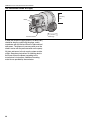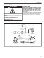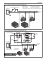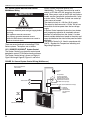
1
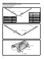
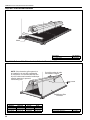
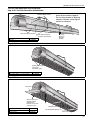
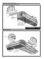
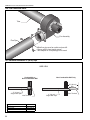
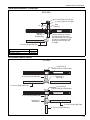
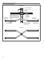
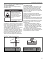
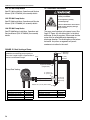
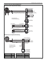
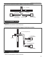
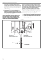
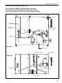
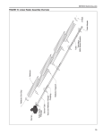
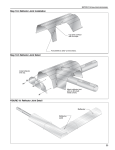
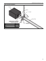
SECTION 9: MULTIBURNER HEATER INSTALLATION Step 9.12 Burner Installation Burner Gasket S-hook Burner Tube Burner must be installed with the flame observation window facing down. Description Bolt Burner Lock Washer Gasket Part Number 94273914 052XXXXX 96411600 02568200 Lock Washer Bolt (Torque 120 in/lb 13.56 Nm) 41 CTHN-SERIES INSTALLATION, OPERATION AND SERVICE MANUAL SECTION 10: OPTIONAL HEATER ACCESSORIES 10.1 Elbow Package Configuration Step 10.1.1 Elbow Installation Tube Coupling Description Elbow Package 90° Elbow Coupling Reflector End Cap Reflector Joint Piece U-Clip Package Part Number 02718702 01335801 01312700 02750800 02750900 91107720 Minimum Distance Required Between Burner and Elbow Minimum Model Distance CTHN-40 10' (3 m) CTHN-60 10' (3 m) CTHN-80 10' (3 m) CTHN-100 15' (4.5 m) CTHN-125 15' (4.5 m) CTHN-150 20' (6 m) CTHN-175 20' (6 m) CTHN-200 20' (6 m) 90° Elbow Step 10.1.2 Elbow Installation Tube Coupling Step 10.1.3 Reflector Joint Installation Reflector Reflector Joint Flatten Edge Scribe Contour 1" (2.5 cm) Maximum 42 SECTION 10: OPTIONAL HEATER ACCESSORIES Step 10.1.4 Reflector Joint Installation Cut away contour with tin snips. Punch/drill six 3/32" (2 mm) holes. Step 10.1.5 Reflector Joint Detail Install reflector end cap. Attach reflector joint with six #8 sheet metal screws. FIGURE 24: Reflector Joint Detail Reflector Reflector Joint 43 CTHN-SERIES INSTALLATION, OPERATION AND SERVICE MANUAL 10.2 Reflector Side Extension Step 10.2.1 Bracket Installation Tube Reflector Tube and Reflector Hanger Reflector Support Reflector Side Extension Bracket (2 per reflector) Use additional supports in high air movement applications. Description Reflector Side Extension Package Reflector Side Extension Retainer Clips Sheet Metal Screws Part Number 02712700 01368000 02751200 94118106 Order Separately Reflector Side Extension Bracket 01329910 Step 10.2.2 Side Reflector Installation #8 x 3/8" Sheet Metal Screw Cut relief notches for supports and hangers. Retainer Clip (2 per side) Reflector Side Extension 44 SECTION 10: OPTIONAL HEATER ACCESSORIES 10.3 Lower Clearance Shield Installation Step 10.3.1 Shield Support Strap Assembly (30 cm) (43 cm) Description Lower Clearance Shield Package Shield Support Strap Lower Clearance Shield 8' (2.4 m) Locknut #8 Flat Washer #8 Screw #8 x 3/8'' Part Number 01397501 01397500 02793000 92311400 95310800 93511406 10.4 Two-Foot Decorative Grille Installation Step 10.4.1 Grille Installation Tube and Reflector Hanger Reflector Tube 2' x 4' (.6 m x 1.2 m) Aluminum Grille Suspended Ceiling Frame Description Aluminum Grille 2' x 4' (.6 m x 1.2 m) Part Number 91407000 45 CTHN-SERIES INSTALLATION, OPERATION AND SERVICE MANUAL Step 10.4.2 Frame Shield Installation Shield Description Deco Grille Shield Part Number 01365900 Step 10.4.3 Reflector Side Extension Installation for Decorative Grilles NOTE: If the decorative grille system is to be installed in an area with considerable air movement, it is recommended that one #8 x 3/8" sheet metal screw be installed per reflector extension to prevent it from blowing over. Cut relief notches for tube and reflector hangers. Insert screw here. A Reflector Side Extension Distance "A" Minimum Maximum 2" (4 cm) 6" (15 cm) 6" (15 cm) 10" (26 cm) 10" (26 cm) 14" (37 cm) 46 Extension Part No. Width 01370408 8" (20 cm) 01370412 12" (30 cm) 01370416 16" (40 cm) Description Reflector Side Extension Part Number 01370412 SECTION 10: OPTIONAL HEATER ACCESSORIES 10.5 One-Foot Decorative Grille Installation Step 10.5.1 One-Foot Decorative Grille Bracket #8 Sheet Metal Screws Decorative Grille Bracket Description Bracket In order to maintain reflector shape, do not fasten brackets together. Do not fasten bracket to adjoining reflectors. Maintain same slipjoint position as reflectors. Cut relief notches for supports and hangers. Part Number 01363003 2" (5 cm) Minimum Bracket Overlap Step 10.5.2 Decorative Grille Spread apart brackets and install decorative grille. Description Decorative Grille 1' x 8' (.3 m x 2.4 m) Part Number 91406700 Step 10.5.3 Joint Piece and Reinforcement Joint Piece Slip joint piece into support bracket and fasten to bracket on one side of the joint only. Description Joint Piece Reinforcement Part Number 01365903 01365902 Reinforcement #8 Sheet Metal Screws Joint Piece 47 CTHN-SERIES INSTALLATION, OPERATION AND SERVICE MANUAL Step 10.5.4 End Piece and Reflector End Cap Reflector End Cap End Piece Insert end piece between grille and brackets. Fasten end piece to brackets using two #8 sheet metal screws and replace reflector end cap. Description End Piece Part Number 01365901 Step 10.5.5 90° Elbow Inside Corner Grille Brackets Joint Piece Insert end piece between grille and brackets. Decorative Grille Brackets 48 Cut grille bracket at reflector joint piece. Joint Piece SECTION 10: OPTIONAL HEATER ACCESSORIES 10.6 Protective Grille Installation Step 10.6.1 Silicone Cap Installation Silicone Cap Description Grille Section Grille End Cap Silicone Cap Grille Finger Part Number 08050001 08050002 91915951-6P Step 10.6.2 Grille End Cap Installation B A Grille Grille End Cap C D Bend up 90° Pull outward Step 10.6.3 Grille Installation Reflector 40" (101 cm) Grille Final Grille Section Grille End Cap 49 CTHN-SERIES INSTALLATION, OPERATION AND SERVICE MANUAL SECTION 11: VENTING - GENERAL WARNING Carbon Monoxide Hazard Multiburner systems are not approved for unvented use and must be vented outdoors. Unitary heaters installed unvented must be interlocked with sufficient building exhaust. Heaters must be installed according to the installation manual. Failure to follow these instructions can result in death or injury. 11.1 General Venting Requirements This heater must be vented in accordance with the rules contained in this manual and with the following national codes and any state, provincial or local codes which may apply: United States: Refer to ANSI Z223.1 (NFPA 54) - latest revision; Canada: Refer to CAN/CGA-B149.1 and B149.2 - latest revision. In brooder installations, affix brooder ventilation wall tag (P/N 91039300) adjacent to the heater thermostat. In the absence of a thermostat, the wall tag must be posted in a conspicuous location. Any portion of vent pipe passing through a combustible wall must have an approved thimble to conform with the above listed codes. Vent pipe must be sloped downward away from the burner 1/2'' (1 cm) for every 20' (6 m). The bottom of the vent or air intake terminal shall not be located less than 1' (.3 m) above grade level. The vent shall not terminate less than 7' (2.1 m) above grade where located adjacent to public walkways. Vent terminal must be installed at a height sufficient to prevent blockage by snow and building materials protected from degradation by flue gases. Secure all joints with #8 x 3/8 sheet metal screws. Seal all joints with high temperature silicone sealant. Vent terminal must be beyond any combustible overhang. For vertical venting, vent shall not extend less than 2' (.6 m) above the highest point where it passes through a flat roof of a building. 50 11.1.1 United States Requirements Vent must terminate at least 3' (.9 m) above any forced air inlet located within 10' (3.1 m). Vent must terminate at least 4' (1.2 m) below, 4' (1.2 m) horizontally from, or 1' (.3 m) above any door, operable window, or gravity air inlet into any building. 11.1.2 Canadian Requirements The vent shall not terminate within 6' (1.8 m) of a mechanical air supply inlet to any building. The vent shall not terminate within 3' (.9 m) of a window or door that can be opened in any building, any non-mechanical air supply inlet to any building, or of the combustion air inlet of any other appliance. SECTION 12: VENTING - UNITARY HEATER SECTION 12: VENTING - UNITARY HEATER All general venting requirements apply. See Page 50, Section 11. Exhaust end of fan will accept a 4'' (10 cm) vent pipe. To prevent leakage of condensation, seal all the vent joints using a high temperature silicone sealant. The heater may be individually vented or common vented. When venting horizontally, a maximum of two heaters can be commonly vented. See Page 53, Section 12.9. When venting vertically, a maximum of four heaters can be commonly vented. See Page 54, Section 12.10. The CTHN unitary heater may also be installed unvented in certain circumstances according to building ventilation codes. Refer to the codes on Page 50, Section 11.1 and Section 12.1 for further information. Unvented operation also requires compliance with the clearances to combustibles given on Page 6, Figure 10. 12.1 Unvented Operation Sufficient ventilation must be provided in the amount of 4 cfm per 1000 Btu/h firing rate (United States); 3 cfm per 1000 Btu/h firing rate (Canada). 12.2 Unvented Operation Termination For unvented operation, turndown type vent terminal with a screen must be installed at the exhaust end of the fan. Vent terminal design shall not incorporate backdraft flap. FIGURE 25: Fan Termination 12.3 Horizontal Venting In noncombustible walls only, vent terminal (P/N 02537801-1P) may be used. For 4'' (10 cm) vents in either combustible or noncombustible walls, use Tjernlund VH1-4 (P/N 90502100) or equivalent, insulated vent terminal. Follow the manufacturer's instructions for proper installation. For 6'' (15 cm) common vents in either combustible or noncombustible walls, use Tjernlund VH1-6 (P/N 90502101) or equivalent, insulated vent terminal. Follow the manufacturer's instructions for proper installation. 12.4 Vertical Venting For 4'' (10 cm), an approved vent cap (P/N 90502300) must be used. For 6'' (15 cm) common vent, an approved vent cap (P/N 90502302) must be used. For common vertical venting of more than two heaters, See Page 54, Section 12.10. 12.5 Length Requirements The maximum vent length allowed is 45' (13.7 m). The maximum outside air supply duct length allowed is 45' (13.7 m). The total vent length, plus outside air duct length and any extensions to minimum heat exchanger lengths, cannot exceed 65' (19.8 m). Vent length should be limited to less than 20' (6 m). If using extended heater lengths or vent lengths greater than 20' (6 m), condensation will form in the vent pipe. Insulation and additional sealing measures (high temperature silicone at all seams) are required. Optional heat exchanger beyond minimum lengths is considered as vent length for length determination. Subtract 15' (4.6 m) of maximum allowed vent or duct length per vent elbow if more than two are used. 51 CTHN-SERIES INSTALLATION, OPERATION AND SERVICE MANUAL 12.6 Flue Connection Detail Tube Fan Assembly Flue Pipe Slide flue pipe over fan outlet and pre-drill. Secure with 3 sheet metal screws. Vent adapter in core package is not used. 12.7 Horizontal Ventilation 4" (10 cm) Pipe SIDE VIEW Combustible or Non-Combustible Wall Non-Combustible Wall Only 18" (46 cm) Min. 4" (10 cm) Single Wall Pipe Description Vent Terminal (Comb. Wall) Vent Terminal Wall Thimble 52 Vent Terminal Part Number 90502100 02537801-XX 90505600 4" (10 cm) Single Wall Pipe Vent Terminal SECTION 12: VENTING - UNITARY HEATER 12.8 Vertical Ventilation 4" (10 cm) Pipe SIDE VIEW 4" (10 cm) Type "B" vent cap 4" (10 cm) Type "B" vent pipe 18" (46 cm) Min. Roof Flashing Roof Approved Thimble (If Applicable) 4" (10 cm) Single Wall Pipe Description Vent Cap 4" (10 cm) Vent Cap 6" (15 cm) The last section of vent pipe passing through the roof or wall may be Type "B" vent pipe. All other vent materials in the building must be single wall vent pipe. Part Number 90502300 90502302 12.9 Common Sidewall Venting TOP VIEW Vent Terminal Tjernlund VH1-6 or Equivalent Outside Wall 6" (15 cm) Single Wall Pipe 4" (10 cm) Single Wall Pipe Sweeping 'T' Connection Vent Terminal Tjernlund VH1-6 or Equivalent Outside Wall 6" (15 cm) Single Wall Pipe Sweeping 'Y' Connection 4" (10 cm) Single Wall Pipe 4" (10 cm) Single Wall Pipe 53 CTHN-SERIES INSTALLATION, OPERATION AND SERVICE MANUAL 12.10 Common Vertical Venting SIDE VIEW Type "B" vent cap Type "B" vent pipe Roof Flashing 18" (46 cm) Min. Roof Vent Adapter at Fan Outlet The last section of vent pipe passing through the roof or wall may be Type "B" vent pipe. All other vent materials in the building must be single wall vent pipe. 4" (10 cm) Single Wall Pipe Top View 54 Approved Thimble (If Applicable) Single Wall Pipe D TOP VIEW D Area must equal sum of open area of individual vents. Vent Adapter at Fan Outlet 4" (10 cm) Single Wall Pipe SECTION 13: VENTING - MULTIBURNER SYSTEMS SECTION 13: VENTING - MULTIBURNER SYSTEMS 13.3 Venting the Pump 13.1 General Requirements See Page 50, Section 11.1. All general venting requirements apply. WARNING Carbon Monoxide Hazard Multiburner systems are not approved for unvented use and must be vented outdoors. Vented heaters must be installed according to the installation manual. Failure to follow these instructions can result in death or injury. 13.2 Manifold Tube Requirements Manifold tube is used to connect radiant tubing to the pump. When more than one burner is connected to a pump, a special connection fitting is utilized, such as a cross or tee section. See Figure 26. It is recommended that 4'' (10.2 cm) O.D. or 6'' (15.2 cm) O.D. aluminized or coated tubing be used for manifold pipe. Reflectors are not required, but may be used over 4'' (10.2 cm) manifold pipe. Manifold pipe must be supported properly, with at least one hanger per 10' (3 m) section. Refer to Page 26, Section 9 for manifold length design requirements. The exhaust connection from the pump is 4'' (10.2 cm) or 6'' (15.2 cm) diameter. Connect one of the flexible isolation boots provided to the flue pipe. Connections to the flue pipe larger than the pump outlet diameter will require the use of an appropriate adapter (not supplied). Venting from the pump may discharge either horizontally or vertically; corrosion resistant pipe is required. See Page 57, Figure 28 for pump vent length requirements. The layout drawing shows the general location of the pump. Specific pump location and discharge details must meet general venting requirements (see Page 50, Section 11 and Section 13.1) as well as the following criteria: • To avoid staining the building wall, extend discharge 3' (1 m) from the building if possible. • Horizontal discharge is preferred, see Page 57, Figure 28. Vertical discharge must be arranged as shown in see Page 56, Figure 27. If the vent pipe is over 20' (6 m) long, insulate it to minimize condensation. Seal all discharge pipe joints with high-temperature silicone or equivalent. FIGURE 26: Tailpipe Connection Points 20" (51 cm) 20" (51 cm) Description Part Number Porcelain Coated Cross, 4'' (10.2 cm) dia 0133092D Aluminized Steel Cross, 4'' (10.2 cm) dia 01330903 Aluminized Steel Cross, 6'' (15.2 cm) dia 01330904 20" (51 cm) 10" (25 cm) Description Porcelain Coated Tee, 4'' (10.2 cm) dia Aluminized Steel Tee, 4'' (10.2 cm) dia Aluminized Steel Tee, 6'' dia (15.2 cm) Part Number 0133022D 01330203 01330204 55 CTHN-SERIES INSTALLATION, OPERATION AND SERVICE MANUAL 13.4 EP-100 Pump Models 13.7 Installation Precautions See EP-100 Installation, Operation and Service Manual (P/N 127201NA) for assembly details. Pumps are shipped partially assembled. 13.5 EP-200 Pump Series Do not operate a partially assembled pump. See EP-200 Installation, Operation and Service Manual (P/N 127200NA) for assembly details. Failure to follow these instructions could result in property damage, injury or death. 13.6 EP-300 Pump Series See EP-300 Series Installation, Operation and Service Manual (P/N 127202NA) for assembly details. The pump scroll attaches to the pump frame (See Page 57, Figure 28) with either right- or left-hand discharge as the job requires. Please note that the motor must be wired differently depending on discharge direction. The discharge must be bottom horizontal. Any other arrangement will permit condensate to collect in the scroll. FIGURE 27: Roof Venting of Pump See sidewall venting illustration for guidelines on matching pump capacity to vent size. Length of pipe is equal to total of vertical and horizontal length. Approved Vent Cap Roof 2' (.6 m) Minimum Approved Thimble (if Applicable) Pump Roof Venting 4" (10 cm) or 6" (15 cm) Tee Single Wall Pipe 4" (10 cm) 6" (15 cm) Drain Cap Attach 1/2" (1.3 cm) line to drain. Description Drain Cap, 4'' (10.2 cm) dia Drain Cap, 6'' (15.2 cm) dia Tee, 4'' (10.2 cm) Tee, 6'' (15.2 cm) 56 Part Number 02718851 02718852 01330203 01330204 Description Vent Cap, 4'' (10.2 cm) Vent Cap, 6'' (15.2 cm) Wall Thimble, 4'' (10.2 cm) Part Number 90502300 90502302 90505600 SECTION 13: VENTING - MULTIBURNER SYSTEMS FIGURE 28: Side Wall Venting Configurations EP-100 or EP-200 Pump Side Wall Venting 18" (46 cm) Minimum 40" (102 cm) Maximum Bird Screen 4" (10 cm) Single Wall Pipe 25' (8 m) and 3 Elbows Maximum for EP-100 10' (3 m) Maximum and no Elbows for EP-200 Approved Thimbles 4" (10 cm) 18" (46 cm) Minimum - Band Clamp 40" (102 cm) Maximum 4" (10 cm) Vent Terminal Pitch single wall pipe downward away from pump 1/4" (6 mm) for every 10' (3 m). Vent Terminal Tjernlund VH1-4 6" to 5" Reducer (15 cm to 12.5 cm) 5" to 4" Reducer (12.5 cm to 10 cm) 5" (12.5 cm) Single Wall Pipe Vent Terminal Tjernlund VH1-6 50' (15 m) and 3 Elbows Maximum for EP-100 25' (8 m) and 3 Elbows Maximum for EP-200 6" to 4" Reducer (15 cm to 10 cm) 6" (15 cm) Single Wall Pipe Vent Terminal Tjernlund VH1-6 50' (15 m) and 3 Elbows Maximum EP-300 Vacuum Pump Side Wall Venting 10' (3 m) Maximum and 1 Elbow 18" (46 cm) Minimum 40" (102 cm) Maximum 10' (3 m) Maximum and 1 Elbow Single Wall Pipe/Tube 6" (15 cm) Pitch single wall pipe downward away from pump 1/4" ( 6 mm) for every 10' (3 m). 6" (15 cm) Band Clamp 6" (15 cm) Bird Screen (Included) Approved Thimble Vent Terminal Tjernlund VH16" (15 cm) or Equivalent (Not Included) Description Part Number Bird Screen 4'' (10 cm) 01365400 Bird Screen, 6'' (15 cm) 01397400 Band Clamp, 4'' (10 cm) 91901300 Band Clamp, 6'' (15 cm) 91913703 Description Wall Thimble, 4'' (10 cm) Vent Terminal, 4'' (10 cm) Vent Terminal, Tjernlund VH1-4 Vent Terminal, Tjernlund VH1-6 Part Number 90505600 02537801-IP 90502100 90502101 57 CTHN-SERIES INSTALLATION, OPERATION AND SERVICE MANUAL SECTION 14: OUTSIDE COMBUSTION AIR SUPPLY The air supply duct may have to be insulated to IMPORTANT: If the building has a slight negative pressure or corrosive contaminants (such as prevent condensation on the outer surface. The halogenated hydrocarbons) are present in the air, an outside air terminal must not be more than 1' (31 cm) outside combustion air supply to the heater is above the vent terminal. required. Seal all combustion air pipe joints. Use of optional outside combustion air is not 14.1 Length Requirements recommended with unvented heaters. Follow the constraints listed on Page 51, Section 12.5. 14.2 Vertical Non-Pressurized Outside Air Supply for Single Heater Installation Vent Cap 18" (46 cm) Min. Roof Flex Hose (Recommended) 4" (10 cm) Single Wall Pipe Burner Band Clamp (Recommended) Description Vent Cap 4" (10 cm) Part Number 90502300 Vent Cap Wall 14.3 Horizontal Non-Pressurized Outside Air Supply for Single Heater Installation 4" (10 cm) Single Wall Pipe Flex Hose (Recommended) Burner Band Clamp (Recommended) Description Vent Cap 4" (10 cm) 58 Part Number 90502300 SECTION 14: OUTSIDE COMBUSTION AIR SUPPLY 14.4 Vertical Non-Pressurized Outside Air Supply for Double Heater Installation Vent Cap Roof 6" (15 cm) Single Wall Pipe Flex Hose (Recommended) Burner Band Clamp (Recommended) Description Vent Cap 6" (15 cm) Sweeping 'T' Connection Burner Flex Hose (Recommended) 4" (10 cm) Single Wall Pipe Part Number 90502302 Requirements: • Heaters must be controlled by a common thermostat. 14.5 Horizontal Non-Pressurized Outside Air Supply for Double Heater Installation Vent Cap Outside Wall 6" (15 cm) Single Wall Pipe Flex Hose (Recommended) Burner Sweeping 'Y' Connection 4" (10 cm) Single Wall Pipe (Seal All Joints) Burner Band Clamp (Recommended) Description Vent Cap 6" (15 cm) Part Number 90502302 Requirements: • Heaters must be controlled by a common thermostat. 59 CTHN-SERIES INSTALLATION, OPERATION AND SERVICE MANUAL 14.6 Pressurized Outside Air Supply 5" (127 mm) Inlet Motor Pressure Switch If used, the outside air supply blower (P/N 90707501) should be wired in parallel with the pump, and in accordance with the National Electric Code and local ordinances. The blower air pressure switch must be wired in series with the pressure switch on the pump. All joints and seams in the air supply system must be airtight. See above instructions on attaching duct to the burner. Mount the blower according to the manufacturer’s instructions. Additional mounting materials are provided by the contractor. 60 5" (127 mm) Discharge SECTION 15: WIRING SECTION 15: WIRING WARNING 15.1 Internal Wiring Heaters must be grounded in accordance with applicable codes: United States: refer to National Electrical Code® ANSI/NFPA 70 - latest revision; Canada: refer to Canadian Electrical Code CSA C22.1 Part I latest revision. If any of the original internal wiring must be replaced, it must be replaced with wiring materials having a temperature rating of at least 105°C and 600 volts. Electrical Shock Hazard Disconnect electrical power and gas supply before servicing. This appliance must be connected to a properly grounded electrical source. Failure to follow these instructions can result in death or electrical shock. 15.2 Internal Wiring COM BLACK N.O. BLACK DOOR SWITCH 3 TERMINAL BUSHING 1 TRANSFORMER WHITE BLACK 120VAC GREEN 1 5 3 4 3 BLUE BLUE PRESSURE SWITCH YELLOW BLUE GREEN YELLOW TH/POWER BROWN V1/VALVE S1/SENSE V2/GND YELLOW BLACK GAS VALVE IGNITER IGNITION MODULE 61 CTHN-SERIES INSTALLATION, OPERATION AND SERVICE MANUAL 15.3 Ladder Diagram L1 L2 FAN 120V TRANSFORMER 24V PRESSURE SWITCH IGNITION MODULE SENSE GAP GAS VALVE 15.4 External Wiring (Unitary Heaters Only) Heaters can be controlled using several methods. Normally thermostats are used to control the heaters, but they can also be controlled by an energy management system. Page 63, Section 15.5 illustrates the connection for heaters controlled by a line voltage thermostat. For single or multiple heaters on one low voltage thermostat, see Page 63, Section 15.6. 62 SECTION 15: WIRING 15.5 Line Voltage Thermostat Wiring (Unitary Heaters Only) CTHN-40 to 150 6-12* burners per thermostat CTHN-175 & 200 3-9* burners per thermostat *(depending on maximum amp load of thermostat chosen) Line Voltage Thermostat 120V-60Hz Supply circuit T L1 Additional Burners L2 L2 Gnd. L1 L2 L1 L2 L1 L2 L1 Fan 2 Fan 1 Burner 1 Burner 2 15.6 Low Voltage Thermostat Wiring (Unitary Heaters Only) FRONT VIEW Transformer Relay 1 4 COIL Black BACK VIEW R 3 2 5 6 COIL W Low Voltage Thermostat C G Y Black 120 V - 60 Hz supply circuit White L1 L2 Red L2 Gnd. CTHN-40 to 150 CTHN-175 & 200 Description Transformer Relay L1 L2 L1 L2 L1 Fan 1 L2 L1 Additional Burners Fan 2 12 Burners Max 6 Burners Max Part Number 90417600 Burner Burner 63 CTHN-SERIES INSTALLATION, OPERATION AND SERVICE MANUAL 15.7 System Control Methods and External Multiburner Wiring WARNING Electrical Shock Hazard Disconnect electrical power and gas supply before servicing. This appliance must be connected to a properly grounded electrical source. Failure to follow these instructions can result in death or electrical shock. There are several methods of controlling CTHNSeries systems. The options are as follows: System Control Installation Manual (P/N 10091601NA). The System Control can be used to control an EP-100 or EP-201 pump from the control panel. Other pumps such as the EP-301 and 3 phase models may be controlled in conjunction with a relay or motor starter. The System Control can control up to four zones of burners. The electrical circuit is a 120 Vac (20 A) supply. The output for the thermostat is 12 Vdc. Do not use thermostats that draw power from the low voltage supply. A System Control operated system has two minutes post purge pump operation to completely exhaust products of combustion from the system. A system control provides indication of power to the pump and zones and indicates the status of the pressure switch with lights. The System Control is UL listed in accordance with UL873 – Standard for Temperature Indicating and Regulating Equipment. 15.7.1 ROBERTS GORDON® System Control The System Control is an electronic control panel designed to control CTHN-Series heating systems. The System Control wiring is shown on Page 64, Figure 29 through Page 66, Figure 32 and in the FIGURE 29: General System Control Wiring (Multiburner) Burner Receptacles 4 Zone Max Pressure Switch Thermostats T T Outside Air Supply Blower Motor and Pressure Switch 120 V 1Ø 60 Hz L N 120 Vac Maximum 20 Amps Total 64 Pump Motor 115 Vac Operation (230 Vac Operation separate power circuit required for EP-203 or EP-300 series pumps) Motor Starter (Needed for EP-203 and EP-300 Series Pump) SECTION 15: WIRING FIGURE 30: External Wiring Diagram EP-100 and EP-201 120 V 1 Ø Pump (Multiburner) Pump All burners must be connected to Ground (Not shown) Zone 1 Zone 2 Zone 3 Zone 4 To additional burners Low voltage thermostats located in heated zone Zone Zone Zone Zone 4 3 1 2 120 V 1Ø 60 Hz Pressure switch located at pump 12 Vdc L C C Z4 PUMP PS Z3 T4 Z2 N L C Z1 N L T3 NL T2 NL C N L T1 L N Ground G Ground C 120 V 1Ø 60 Hz N System Control FIGURE 31: External Wiring Diagram EP-301 230 V 1 Ø Pump (Multiburner) EP 301 Pump Do not directly connect the controller relay terminals to the pump motor, product damage will result. Contactor rated for the EP 301 pump motor All burners must be connected to ground (not shown). Zone 1 Zone 2 Zone 3 Zone 4 6 4 The power supply for the pump must be separate from the controller supply 2 M 3 1 208 - 230 V 1 Ø Individual supply for 60 Hz pump rated for total full 5 N L 120 V 1Ø 60 Hz 120 V 1Ø 60Hz load current. See Pump Specifications Section for details. Low voltage thermostats located in heated zone Zone Zone Zone 1 2 3 L Pressure switch located at pump Zone 4 N 12V DC C PS T4 C NL Z4 PUMP C NL T3 Z3 C NL Z2 T2 NL Z1 C NL T1 L N Ground G Ground System Control Description Contactor Part Number 10050009 65 CTHN-SERIES INSTALLATION, OPERATION AND SERVICE MANUAL FIGURE 32: External Wiring Diagram EP-203 or EP-303 3 Ø Pump (Multiburner) Motor starter rated for EP-203 pump motor; motor starter rated for EP-303 pump motor. EP-203 or EP- 303 3 Ø Pump Do not directly connect the controller relay terminals to the pump motor, product damage will result. The power supply for the pump must be separate from the controller supply All burners must be connected to ground (not shown). OL Zone 1 Zone 2 Zone 3 Zone 4 M L3 L2 L1 120 V 1Ø 60 Hz 120 V 1Ø 60 Hz 208 - 230 V (or 460 V) 3Ø 60 Hz Individual supply for pump rated for total full load current. See Pump Specification Section for details. Low voltage thermostats located in heated zone Zone Zone Zone 1 2 3 Zone 4 Pressure switch located at pump L N 12 Vdc C PS Part Number 10050001 10050010 15.7.2 SPST Transformer Relay (P/N 90417600) The transformer relay wiring diagram is shown on Page 67, Figure 33. The transformer relay can be used to control an EP-100 or EP-201 pump CTHN system. The single pole relay can only be used to control one zone of burners. The electrical circuit is a 120V AC (20 A) supply. The transformer 24V AC output for the thermostat is rated at 40VA. Thermostats used with the transformer must not exceed this power requirement. A transformer relay operated system will not give any post purge pump operation to completely exhaust products of combustion from the system or provide indication of operating conditions. 66 T4 Z4 PUMP System Control Description Motor Starter for EP-203 Motor Starter for EP-303 C NL C NL T3 Z3 C NL Z2 T2 NL Z1 C NL T1 L N Ground G Ground 15.7.3 DPST Transformer Relay (P/N 90436300) The transformer relay wiring diagram is shown on Page 68, Figure 34. The transformer relay can be used to control an EP-100 or EP-201 pump CTHN system. The double pole relay can only be used to control two zones of burners. The electrical circuit is a 120V AC (20 A) supply. The transformer 24V AC output for the thermostat is rated at 40VA. Thermostats used with the transformer must not exceed this power requirement. A transformer relay operated system will not give any post purge pump operation to completely exhaust products of combustion from the system or provide indication of operating conditions. SECTION 15: WIRING FIGURE 33: One Zone Operation without Control Panel (Multiburner) SPST (12A) Transformer Relay R C W G Y Thermostat Black 120 V 1Ø 60 Hz 1 2 4 COIL L Black N White 5 3 6 COIL Ground Red Pump Motor L L N N Pressure Switch (Pump) Zone 1 Burners Nine Burners Maximum Description SPST Transformer Relay Part Number 90417600 67 CTHN-SERIES INSTALLATION, OPERATION AND SERVICE MANUAL FIGURE 34: Two Zone Operation without Control Panel (Multiburner) DPST (12 A) Transformer Relay DPST (12 A) Transformer Relay C R W G R C W G Y Y Zone 2 Thermostat Zone 1 Thermostat Purple 1 4 COIL 3 2 6 COIL 5 Red 1 Purple 2 4 COIL Red 5 3 6 COIL Black 120 V 1Ø 60 Hz Black Black Red/Yellow White White L Red/Yellow Black N L L Pressure Switch (Pump) 68 Part Number 90436300 L N N Pump Motor Description DPST Transformer Relay N Zone 1 Burners Zone 2 Burners Nine Burners Total Maximum Between Zones SECTION 16: GAS PIPING SECTION 16: GAS PIPING There is an expansion of the tube with each firing cycle. This will cause the burner to move with respect to the gas line. This can cause a gas leak resulting in an unsafe condition if the gas connection is not made strictly in accordance with Figure 35. WARNING Fire Hazard Tighten gas hose fittings to connect gas supply according to Figure 35. Gas hose can crack when twisted. Gas hose moves during normal operation. Failure to follow these instructions can result in death, injury or property damage. Install the gas hose as shown in Figure 35. The flex gas hose connector accommodates expansion of the heating system and allows for easy installation and service of the burner. Before connecting the burners to the supply system, verify that all high pressure testing of the gas piping has been completed. Meter and service must be large enough to handle all the burners being installed plus any other connected load. The gas line which feeds the system must be large enough to supply the required gas with a maximum pressure drop of 1/2" wc When gas piping is not included in the layout drawing, the local gas supplier will usually help in planning the gas piping. • Do not high pressure test the gas piping with the burner connected. Failure to follow these instructions can result in property damage. • Check the pipe and tubing ends for leaks before placing heating equipment into service. When checking for gas leaks, use a soap and water solution; never use an open flame. FIGURE 35: Gas Connection with Flexible Gas Hose Hold gas nipple securely with pipe wrench when attaching the gas hose. Failure to follow these instructions can result in product damage. Shut-Off Valve must be parallel to burner gas inlet. The 2" (5 cm) displacement shown is for the cold condition. This displacement may reduce when the system is fired. Shut-Off Valve (Included With Gas Hose) 2" (5 cm) 12" (30 cm) 45° Side View Horizontal Flexible Gas Hose Description 1/2" Flexible Stainless Steel Gas Hose (US Models) 3/4" Flexible Stainless Steel Gas Hose (US Models) 1/2" Rubber (Type 1) Gas Hose (Canadian Models) 3/4" Rubber (Type 1) Gas Hose (Canadian Models) Rear View Part Number 91412200 91412203 91412206 91412207 69 CTHN-SERIES INSTALLATION, OPERATION AND SERVICE MANUAL SECTION 17: OPERATION AND MAINTENANCE The CTHN-Series heater is equipped with a direct spark ignition system. WARNING 5. If a flame is detected, the gas valve remains open. When the call for heat is satisfied the thermostat turns off the burner and fan power supply. 6. If the flame extinguishes during operation, the ignition module will attempt to re-establish the flame as described in the preceding step. If ignition is not re-established, the module will lock-out. Explosion Hazard Service and annual inspection must be done by a contractor qualified in the installation and service of gas-fired heating equipment or your gas supplier. Turn off gas and electrical supplies before performing service or maintenance. Failure to follow these instructions can result in death, injury or property damage. 17.1 Checking the Gas Line 1. Open main valve and verify that no gas is flowing through the gas meter. 2. Purge the line if this was not done following pressure testing with air. 3. Verify that the gas pressure is not above 14" wc (1/2 PSIG) 4. Close main gas valve. 17.2 Unitary Heater Sequence of Operation 1. Turn the thermostat up. When the thermostat calls for heat, the blower motor will energize. 2. When the fan motor achieves normal running RPM, the pressure switch within the burner closes and energizes the ignition module. 3. After a 45 second pre-purge, the ignition module then opens the gas valve and energizes the electrode. When the flame is established, the sparking sequence ceases. 4. If the flame is not established during the ignition sequence, the ignition module closes the gas valve and purge begins. The ignition module will try 2 additional times for ignition (with purge between). If ignition is not established, the module will lock-out. NOTE: After 1 hour, the module will reset automatically and return to steps 3 and 4. 70 7. After lock-out, the control must be reset by turning down the thermostat for five seconds, then raising it again to the desired temperature, or by disconnecting and re-connecting power to the control. 17.2.1 To Shut Off Heater - Unitary Set thermostat to lowest setting. Turn OFF electric power to heater. Turn OFF manual gas valve in the heater supply line. 17.2.2 To Start Heater - Unitary Turn gas valve and electric power OFF and wait five minutes for unburned gases to vent from heater. Turn ON main gas valve. Turn ON electric power. Set thermostat to desired temperature. Burner should light automatically. Once the heater is operating, keep away from heater. Do not touch any part of the heater because it is very hot. 17.3 Multiburner System Operation 17.3.1 Checking the Electrical System 1. Set all thermostats below room temperature. 2. Turn on power supply to the system controls. 3. Check to see that no part of the system (i.e. burners, pump, outside air supply blower) is powered. 4. Individually check each zone by energizing the thermostats separately. Each zone thermostat should start the pump immediately. When the pump reaches the nominal running RPM, the SECTION 17: OPERATION AND MAINTENANCE pressure switch closes and activates the ignition module. A pre-purge period will precede burner ignition trial. 5. If more than one system is installed, be sure that no part of one system is affected by the controls of a different system. 6. Make a preliminary vacuum check at burners in branches which have an adjustable damper coupling. See Page 72, Figure 36 for vacuum measuring instructions. This check is to ensure that all dampers are open before the system is fired. The vacuum measured in the burner control housing should be more than .75" wc. 17.3.2 Starting the System - Multiburner Note: During the initial firing, the protective oil on the tube may smoke for 30 to 60 minutes and adequate ventilation should be provided. 1. Start with all thermostats below room temperature. 2. Open main gas valve. 3. Turn up thermostats one at a time, waiting to see that all burners in a zone start. When the burner ignites, a blue flame will be observed through the viewer window. 4. If any abnormal operation occurs, see Page 76, Section 18. 17.3.3 Sequence of Operation - Multiburner 1. Thermostat, on a call for heat, signals the control panel or relay contacts to energize the pump motor. The pump (and outside air supply blower, if used) are activated. the burner, the pressure switch within the burner closes and energizes the ignition module. 5. After a 45 second pre-purge, the ignition module opens the gas valve and energizes the electrode. When the flame is established, the sparking sequence ends. 6. If the flame is not established during the ignition sequence, the ignition module closes the gas valve and purge begins. The ignition module will try 2 additional times for ignition (with purge between). If ignition is not established, the module will lock-out. NOTE: After 1 hour, the module will reset automatically and return to steps 5 and 6. 7. If a flame is detected, the gas valve remains open. When the call for heat is satisfied, the system control or relay de-energizes the burner and pump power supply. When using the system control, the pump turns off after a post-purge period. 8. If the flame extinguishes during operation, the ignition module will attempt to re-establish the flame. If ignition is not re-established, the module will lock-out. 9. After lock-out, the control must be reset by turning down the thermostat for five seconds, then raising it again to the desired temperature, or by disconnecting and re-connecting power to the control. 17.3.4 To Shut Off Heater - Multiburner See Page 70, Section 17.2.1. 2. When the pump motor achieves normal running RPM, the pressure switch at the pump inlet closes. 17.3.5 To Start Heater - Multiburner 3. After a minimum 45-60 second pre-purge delay (system control only), the zone relay corresponding to the thermostat calling for heat is energized (system control only), and line voltage is directed to the burners in the zone. 17.3.6 Setting the Vacuum - Multiburner 1. Set thermostats above room temperature. See that all burners are operating properly. 4. When sufficient vacuum differential (see Page 71, Section 17.3.6) is available at the burner and the control system is supplying line voltage to See Page 70, Section 17.2.2 2. Allow at least one-half hour operation for temperature to normalize before checking system vacuum balance. Vacuum differential can be measured by connecting a manometer 71 CTHN-SERIES INSTALLATION, OPERATION AND SERVICE MANUAL across the “tee” tappings inside the control housing (after measurement, the caps must be installed on the “tees” to prevent leakage). See Figure 36 for manometer connection to burner control housing. 3. Approximately 1.0'' of vacuum differential is required at the burner when the system is cold. Normal operating (hot) differential of the burners should be adjusted to .75" wc. Vacuum adjustments are made by means of the pump inlet damper and the adjustable damper coupling(s). Check the vacuum differential at all burners, then adjust the damper coupling to obtain equal vacuum differential readings. Adjust the pump inlet damper until vacuum differentials at the burners are as given above. With systems designed to capacity, it may not be possible to obtain vacuum differential readings at slightly above 1" wc (when cold). If so, adjust damper couplings to maximum but approximately equal vacuum readings. Be sure to lock all dampers securely after adjustment. 4. Reset thermostats to desired room temperature. 5. If heat is not required, turn off main switch and close main gas valve. FIGURE 36: Vacuum Differential Reading Burner Burner Remove Cap Remove cap, Attach Manometer Hose attach manometer hose. Remove Cap Remove cap, Attach Manometer Hose attach manometer hose. 2 1 0 .75" w.c. 1 2 72 Manometer Manometer SECTION 17: OPERATION AND MAINTENANCE 17.4 Maintenance 17.4.1 Pre-Season Maintenance and Annual Inspection WARNING Explosion Hazard Service and annual inspection must be done by a contractor qualified in the installation and service of gas-fired heating equipment or your gas supplier. Turn off gas and electrical supplies before performing service or maintenance. Failure to follow these instructions can result in death, injury or property damage. To ensure your safety and years of trouble-free operation of the heating system, service and annual inspections must be done by a contractor qualified in the installation and service of gas-fired heating equipment. Turn off gas and electric supplies before performing service or maintenance. Allow heater to cool before servicing. Before every heating season, a contractor qualified in the installation and service of gas-fired heating equipment must perform a thorough safety inspection of the heater. For best performance, the gas, electrical, thermostat connections, tubing, venting, suspensions and overall heater condition should be thoroughly inspected. NOTE: Gas flow and burner ignition are among the first things that should be inspected. Please see Page 74, Section 17.5 for suggested items to inspect. 73 CTHN-SERIES INSTALLATION, OPERATION AND SERVICE MANUAL 17.5 Maintenance Checklist WARNING Explosion Hazard Service and annual inspection must be done by a contractor qualified in the installation and service of gas-fired heating equipment or your gas supplier. Turn off gas and electrical supplies before performing service or maintenance. Failure to follow these instructions can result in death, injury or property damage. The Vicinity of the Heater Installation Code and Annual Inspections: All installations and service of ROBERTS GORDON® products must be performed by a contractor qualified in the installation and service of products sold and supplied by Roberts-Gordon and conform to all requirements set forth in the ROBERTS GORDON® manuals and all applicable governmental authorities pertaining to the installation, service and operation of the equipment. To help facilitate optimum performance and safety, Roberts-Gordon recommends that a qualified contractor annually inspect your ROBERTS GORDON® products and perform service where necessary, using only ROBERTS GORDON® replacement parts. Do not store or use flammable objects, liquids or vapors near the heater. Immediately remove these items if they are present. See Page 3, Section 3. Vehicles and Other Objects Maintain the clearances to combustibles. Do not hang anything from, or place anything on, the heater. Make sure nothing is lodged underneath the reflector, in between the tubes or in the decorative or protective grilles (included with select models). Immediately remove objects in violation of the clearances to combustibles. See Page 3, Section 3. Reflector Make sure there is no dirt, sagging, cracking or distortion. Do not operate if there is sagging, cracking or distortion. Make sure reflectors are correctly overlapped. See Page 23, Section 8.9.1. Clean outside surface with a damp cloth. Vent Pipe Venting must be intact. Using a flashlight, look for obstructions, cracks on the pipe, gaps in the sealed areas or corrosion. The area must be free of dirt and dust. Remove any carbon deposits or scale using a wire brush. Inspect pump and flue pipe for soot or dirt or any obstruction to the outdoors. After cleaning as necessary, reattach the flue pipe to the heater. Inspect acoustical boots for cracks and leaks. Replace as necessary. See Page 50, Section 11. Outside Air Inlet Inlet must be intact. Look for obstructions, cracks on the pipe, gaps in the sealed areas or corrosion. The area must be free of dirt and dust. Clean and reinstall as required. 74 SECTION 17: OPERATION AND MAINTENANCE Tubes Make sure there are no cracks. Make sure tubes are connected and suspended securely. See Page 10, Figure 12. Make sure there is no dirt, sagging, bending or distortion. Clean or replace as required. Gas Line Check for gas leaks. See Page 69, Section 16. Burner Observation Window Make sure it is clean and free of cracks or holes. Blower Scroll, Wheel and Motor Compressed air or a vacuum cleaner may be used to clean dust and dirt. Burner Cup and Orifice Make sure it is clear of obstructions (even spider webs will cause problems). Clean or replace as required. Carefully remove any dust and debris from the burner. Electrode Replace if there are cracked ceramics, excessive carbon residue, or erosion of the electrode. The electrode gap should be 1/8" (3.2 mm). Thermostat There should be no exposed wire or damage to the thermostat. See Page 63, Section 15.5. Suspension Points Make sure the heater is hanging securely. Look for signs of wear on the chain or ceiling. See Page 10, Figure 12. Decorative and Protective The grille must be securely attached. Grille (optional) Check that side reflector extensions are installed correctly and secured in place if necessary. (Decorative grille only.) See Page 45, Section 10.4 through Page 49, Section 10.6 Make sure shield is installed correctly and secured in place if necessary. (Decorative grille only.) See Page 46, Section 10.4.2. Lower Clearance Shield (optional) The lower shield must be securely attached. See Page 45, Section 10.3 . Make sure shield is installed correctly and secured in place if necessary. See Page 45, Section 10.3.1. 75 76 After a 45 pre-purge period, does the burner light? Yes Turn up thermostat. Does the pump turn on? No No Yes Yes Repair or Replace switches as necessary. Replace main control board. (P/N 90437500) Replace pressure switch. (P/N 90436701) Repair, replace or tighten hoses as necessary. Remove obstruction. No No No No Yes Reconnect MBR and MBR-COM. Are the vacuum Yes proving and/or motor end switches operating properly? Disconnect wires from MBR and MBR-COM. Is there at least Yes 12V DC between the terminals? No Is there power (120V) at the Yes burner receptacle? No Check wiring to the burner. Make sure the burner is plugged in. Replace main control board. Yes (P/N 90437500) Replace fuse. (P/N 90438200) 250V 3A size 3AG Test thermostat by placing a jumper wire between COM and appropriate thermostat No T(1,2,3,4) terminal. Does the pump turn on? Is there power (120V) between control panel BH and BN Yes terminals of the zone calling for heat. Check circuit breaker and/or fuse on panel supply circuit. No Is there power (120V) to the control panel H and N Yes terminals? Check thermostat wiring and replace thermostat if necessary. Yes No Remove the blue and yellow wires from the transformer. Is there 24V at the transformer secondary? No Yes Yes Replace transformer. (P/N 90436900) Yes With the blue and yellow wires still removed, is the voltage at No the transformer black and white leads 120V? Reconnect transformer wires. Place a jumper wire across the pressure switch. Is there a spark? Yes No Check vacuum differential reading. Is it okay? Reset dampers Carefully reset spark gap to 1/8". Yes No Is the igniter gap set at 1/8"? Replace Door. No Is blower side door in place? Replace pump relay. (P/N 90437900, Omron G4B112T1-US, or equivalent) No Yes Yes No Disconnect power to the motor. Does the motor turn freely? No No Is the motor hot? Are the air hoses to the pressure switch secure and leak free? Is the vent pipe or the inlet of the burner obstructed? Replace appropriate zone relay on main board. (P/N 90438100, Omron G2R-1-S, or equivalent) Is there proper gas pressure Yes and flow to the burners? No Correct gas problem. See Gas Piping Section for details. Is there at least 12V DC at the pump relay coil? (W2 and W1 No on circuit board.) No Is the fuse on the circuit board blown? No Is there power (120V) between the panel MH and MN terminals? Is the motor connected properly? Refer to the wiring diagrams on the motor and in the installation manual Yes Check wiring between the power cord and transformer. Replace igniter and ignition wire as needed. Yes Unplug burner and check igniter and ignition wire. Are they damaged? Check wiring and Diagram. No No Remove door. Is voltage at door switch 120V? Check voltage between door Yes switch and burner neutral (white). Motor bearings may have failed. Replace motor. No Is the pump impeller obstructed? Motor may have tripped overload switch. Wait 10-15 minutes for automatic reset. Is there spark at the igniter? Yes Depress switch. Check voltage. Is it 120V? Check voltage between door No switch and burner neutral (white). Remove obstruction. Replace Switch CTHN-SERIES INSTALLATION, OPERATION AND SERVICE MANUAL SECTION 18: TROUBLESHOOTING 18.1 Troubleshooting Flow Chart - Unitary No Do all the burners ignite smoothly? No Troubleshoot ends. If problem persists, contact your No local ROBERTS-GORDON® Representative. Yes Does the pump shut down after a 45 second post-purge period? Yes Do burners shut off after the call No for heat is satisfied? Yes Yes No Does the burner stay on? Yes Yes Contact Roberts-Gordon at www.rg-inc.com Make sure that all thermostats (including SmartSet and Yes Night Set Back) are satisfied. Make sure that all thermostats (including SmartSet and Night Set Back) are established. Yes No No Disconnect all thermostat wires from COM. Does the pump Yes continue to run after a 45 sec. post-purge period? Check thermostat wiring for shorts and replace thermostat if necessary. Yes Yes Replace ignition module. (P/N 90434002K) No Turn valve on. Replace main control board. (P/N 90437500) No Reconnect thermostat wires. Disconnect W1 wire from pump relay. Does the pump Yes still run? Replace pump relay. (P/N 90437900, Omron G4B112T1-US, or equivalent) Replace main control board. (P/N 90437500) Ignition module may have failed. Replace module. (P/N 90434002K) Are the wires connecting the ignition module OK? No Is the knob on the gas valve in the on position. No No Replace/Correct wires. Check gas line stop cock. Contact gas company. No Is the inlet gas pressure during ignition correct? (Natural 4.6" Yes min, 5.0 for EV-175, -200, LP should be 11.0" min) Yes Measure voltage on valve terminals. Is there 24V during ignition period? Yes Is there gas outlet pressure available during the ignition period? No Replace door. Does the burner light? Were the gas lines purged of air? Purge Lines. No Yes Yes Is the gas outlet pressure 3.5" for Natural Gas (10.5" for LP)? Check for the proper orifice and air plate inside the burner. With the thermostats connected, measure the voltage between the thermostat terminals (T1, T2, T3, T4, SCT and NST) and the Yes COM terminal. Are all the voltages 5V. Adjust system for proper vacuum. See venting section for details. Is the vacuum setting to high? Yes Re-Establish Continuity. Re-Establish Continuity. Is the insulation on the igniter/sensor leads OK? No Yes Yes Replace gas valve. (Natural P/N 90032500) (LP P/N 90032502) No Is the continuity of the earth wire established? No Adjust the valve pressure. Yes Replace ignition module. (P/N 90434002K) SECTION 18: TROUBLESHOOTING 77 78 NO Is there spark at the igniter? NO YES Turn up thermostat. Does the fan turn on? START Carefully reset igniter gap to 1/8" Replace igniter and ignition wire as needed. NO Replace ignition module. NO Reconnect transformer wires. Place a jumper wire across the pressure switch. Is there a spark? Replace transformer. Remove the blue and yellow wires from the transformer. Is there 24 V at the transformer secondary? YES Are the air hoses to the pressure switch secure and leak free? NO YES NO Is the vent pipe or the inlet of YES the burner obstructed? YES NO YES YES With the blue and yellow Check wiring between the NO wires still removed, is the power cord, fan motor voltage at the transformer and transformer. black and white leads 120 V? NO YES Is the igniter gap set at 1/8"? Replace fan. Check relay wiring (if applicable) and wiring to the fan. Check thermostat wiring and replace thermostat if necessary. Unplug burner and check igniter and ignition wire. Are NO they damaged? YES Unplug fan. Does the fan turn freely? NO Is there power (120 V) at YES the fan? YES Place a jumper across the NO thermostat terminals. Does the blower turn on? Replace pressure switch. Repair, replace, or tighten hoses as necessary. Remove obstruction. Fan bearings may have failed. Replace fan. NO Is the fan obstructed? YES Remove obstruction. CTHN-SERIES INSTALLATION, OPERATION AND SERVICE MANUAL 18.2 Troubleshooting Flow Chart - Multiburner NO NO NO Contact Roberts-Gordon at www.rg-inc.com. Check the thermostat and check the continuity of the ground wire. Replace/correct wires. NO Are the wires connecting the module and electrode OK? Replace/correct wires. NO YES Replace ignition module. Replace ignition module. YES Turn valve ON. NO Is the knob on the gas valve in the ON position? Are the wires connecting the ignition module OK? Is there gas outlet pressure available during the ignition period? Check gas line stop cock. Contact gas company. YES YES YES Is the gas outlet pressure NO 3.5" for Natural Gas (10.5" for LP)? NO Measure voltage on valve terminals. Is there 24 V during ignition time? Purge lines. NO Is the inlet gas pressure during ignition correct? (Natural 4.6" YES min., LP should be 11.0") YES Were the gas lines purged of air? YES NO NO TROUBLESHOOT ENDS. If problems persist, contact OR your ROBERTS GORDON® Independent Distributor. YES Does the burner turn off when the call for heat ends? YES Does the burner stay on? YES Does the burner light? YES Check for the proper orifice and air plate inside the burner. Replace gas valve. Adjust the valve pressure. See the manifold gas pressure settings SECTION 18: TROUBLESHOOTING 79 CTHN-SERIES INSTALLATION, OPERATION AND SERVICE MANUAL 18.3 Manifold Gas Pressure Setting Top View of Heater Manometer 6 5 4 3 2 1 0 1 2 3 4 5 6 Natural 80 3.5" 6 5 4 3 2 1 0 1 2 3 10.5" 4 5 6 Propane SECTION 19: REPLACEMENT PARTS LIST SECTION 19: REPLACEMENT PARTS LIST Use only genuine ROBERTS GORDON® replacement parts. Use of parts not specified by Roberts-Gordon voids warranty. Failure to follow these instructions can result in property damage. Door Switch Burner Cup Assembly Mica Window Assembly Air Adapter Collar Electrode TOP VIEW Ignition Module Pressure Switch Gas Valve SIDE VIEW Tube Gasket Transformer 81 CTHN-SERIES INSTALLATION, OPERATION AND SERVICE MANUAL Replacement Parts List (continued...)* Description Burner Gas Valve (Natural) Gas Valve (LP) Burner Cup Assembly Mica Window Assembly Electrode Electrode Gasket Ignition Module Ignition Wire Pressure Switch: (40, 80) (60, 100, 125, 150) (175,200) Transformer Door Switch Air Adapter Collar Tube Gasket Outside Air Supply Blower Air Supply Blower/Power Venter Part Number 90032500 90032502 03020100 02553203 90427400 02558501 90439500K 90427706 90439803K 90439810K 90439802K 90436900K 90436800 91911700 02568200 90707501 * For all other accessories, see Page 11, Section 8.1, Page 26, Section 9.1, Page 12, Table 4 and Page 27, Table 9. 82 SECTION 20: GENERAL SPECIFICATIONS SECTION 20: GENERAL SPECIFICATIONS 20.1 Material Specification 20.1.1 Reflectors .024 Aluminum (Optional .024 Stainless Steel Type 304) 20.2 Heater Specifications 20.2.1 Control System 20.3 Suspension Specifications Hang heater with materials with a minimum working load of 75 lbs (33 kg). See Page 10, Figure 12. 20.4 Controls Specifications Time switches, thermostats, etc. can be wired into the electrical supply. External controls supplied as an optional extra. Fully automatic spark ignition with safety shut-off. General Specifications for the heaters are as follows: End View Side View Minimum Length "A" Reflector 13.5" (34 cm) 9.5" (24 cm) Burner Tube 17.5" (44 cm) Length ''A'' Minimum Unitary Multiburner Turbulator (Select Models) Recommended Minimum Mounting Height* Space Spot Model Heat Input Rate (Btu/h) x (1000) CTHN-40 40 10' (3 m) 20' (6 m) 8'-10' (2.4 - 3 m) 8' (2.3 m) CTHN-60 60 20' (6 m) 30' (9 m) 10'-12' (3 - 3.6 m) 9' (2.7 m) CTHN-80 90 20' (6 m) 30' (9 m) 12'-15' (3.6 - 4.5 m) 11' (3.3 m) CTHN-100 100 30' (9 m) 40' (12 m) 12'-15' (3.6 - 4.5 m) 12' (3.7 m) CTHN-125 125 40' (12 m) 50' (15 m) 15'-20' (4.5 - 6 m) 15' (3.7 m) CTHN-150 150 40' (12 m) 50' (15 m) 20'-25' (6 - 7.6 m) 20' (4.6 m) CTHN-175 175 50' (15 m) 60' (18 m) 25' (7.6 m) 23' (6 m) CTHN-200 200 50' (15 m) 60' (18 m) 25' (7.6 m) 25' (7.6 m) *See Page 3, Section 3 for clearances to combustibles. GAS PRESSURE AT MANIFOLD: Natural Gas: 3.5" wc LP Gas: 10.5" wc PIPE CONNECTION: 1/2" NPT (for CTHN-40, 60, 80, 100, 125) 3/4" NPT (for CTHN-150,175 & 200) DIMENSIONS: Vent Connection Size: 4" (10 cm) Outside Air Connection Size: 4" (10 cm) Refer to figure above for dimensional information. GAS INLET PRESSURE: Natural Gas: for CTHN-40, 60, 80, 100, 125, 150 for CTHN-175, 200 LP Gas: All Models ELECTRICAL RATING: Unitary Models 40-150: Unitary Models 175-200: Multiburner All Models: 4.6" wc Minimum 5.0" wc Minimum 14.0" wc Maximum 11.0" wc Minimum 14.0" wc Maximum 120 V - 60 Hz, 1 A 120 V - 60 Hz, 2 A 120 V - 60 Hz, 0.1 A 83 CTHN-SERIES INSTALLATION, OPERATION AND SERVICE MANUAL General Specifications for fans and pumps are as follows: Pump Dimensional Data (in.) Model A B EP-100 17 14.5 EP-201/203 17.75 17 EP-301/303 25.6 24.8 C 21 20.25 22.7 D 3.75 3.25 4.8 E 10 10 15.2 F 4 4.5 6 G 4 4.5 6 G A D E B C F dia. Fan and Pump Specifications Model Horsepower (Hp) 05220000 05221000 EP-100 EP-201 EP-203 EP-301 EP-303 .134 .23 1/3 3/4 3/4 2* 2* Phase (Ø) 1 1 1 1 3 1 3 Hertz (Hz) 60 60 60 60 60 60 60 Voltage (V) 115 115 115/230 115/230 208-230/ 460 208-230 208-230/ 460 .9 1.6 4.8/2.4 6.6/3.3 2.4-2.2/1.1 12.8-11.5 5.5-5.2/2.6 3200 3200 3450 3450 3500 3450 3450 Motor Frame - - 56 56 56 90 90 Motor Enclosure - - TENV TENV TEFC TEFC TEFC Noise Level @ 5' (DBA) - - - 70 70 - - Inlet/Outlet (In.) 4/4 4/4 4/4 4/4 4/4 6/6 6/6 Weight (lbs.) 10 12 62 112 112 170 170 Full Load Amp (Amps) R.P.M. * For starter, see National Electric Code (NEC) requirement for motors 1 hp or higher. Air Supply Blower Specifications Capacity Power (W) 240 CFM @ 0.75 in wc 167 Phase 1 Hertz (Hz) 60 Voltage (V) 120 Full Load Amp (Amps) 1.5 R.P.M. 3000 Motor Enclosure OPEN FC Inlet/Outlet (In.) 5/5 Weight (lbs.) 10 84 SECTION 21: THE ROBERTS GORDON® VANTAGE® NP LIMITED WARRANTY SECTION 21: THE ROBERTS GORDON® VANTAGE® NP LIMITED WARRANTY The ownership of the ROBERTS GORDON® VANTAGE® ROBERTS-GORDON WILL PAY FOR: Within 42 months from date of shipment from RobertsGordon, replacement parts will be provided free of charge for any part of the product which fails due to a manufacturing or material defect. Roberts-Gordon will require the part in question to be returned to the factory. Roberts-Gordon will, at its sole discretion, repair or replace after determining the nature of the defect and disposition of part in question. ROBERTS GORDON® Replacement Parts are warranted for a period of 18 months from date of shipment from Roberts-Gordon or the remaining ROBERTS GORDON® VANTAGE® NP warranty. ROBERTS-GORDON WILL NOT PAY FOR: Service trips, service calls and labor charges. Shipment of replacement parts. Claims where the total price of the goods have not been paid. Damage due to: • Improper installation, operation or maintenance. • Misuse, abuse, neglect, or modification of the ROBERTS GORDON® VANTAGE® NP in any way. • Use of the ROBERTS GORDON® VANTAGE® NP for other than its intended purpose. • Incorrect gas or electrical supply, accident, fire, floods, acts of God, war, terrorism, or other casualty. • Improper service, use of replacement parts or accessories not specified by Roberts-Gordon. • Failure to install or maintain the ROBERTS GORDON® VANTAGE® NP as directed in the Installation, Operation and Service manual. • Relocation of the ROBERTS GORDON® VANTAGE® NP after initial installation • The use of the ROBERTS GORDON® VANTAGE® NP in a corrosive atmosphere containing contaminants. • The use of the ROBERTS GORDON® VANTAGE® NP in the vicinity of a combustible or explosive material. • Any defect in the ROBERTS GORDON® VANTAGE® NP arising from a drawing, design, or specification supplied by or on behalf of the consumer. • Damage incurred during shipment. Claim must be filed with carrier. WARRANTY IS VOID IF: NP is moved or transferred. This warranty is nontransferable. Roberts-Gordon is not permitted to inspect the damaged controller and/or component parts. READ YOUR INSTALLATION, OPERATION AND SERVICE MANUAL. If you have questions about your controller, contact your installing professional. Should you need Replacement Parts or have additional questions, call or write RobertsGordon: U.S.A. 1250 William Street P.O. Box 44 Buffalo, New York 14240-0044 716.852.4400 On the web at: www.rg-inc.com Roberts-Gordon's liability, and your exclusive remedy, under this warranty or any implied warranty (including the implied warranties of merchantability and fitness for a particular purpose) is limited to providing replacement parts during the term of this warranty. Some jurisdictions do not allow limitations on how long an implied warranty lasts, so this limitation may not apply to you. There are no rights, warranties or conditions, expressed or implied, statutory or otherwise, other than those contained in this warranty. Roberts-Gordon shall in no event be responsible for incidental or consequential damages or incur liability for damages in excess of the amount paid by you for the ROBERTS GORDON® VANTAGE® NP. Some jurisdictions do not allow the exclusion or limitation of incidental or consequential damages, so this limitation or exclusion may not apply to you. This warranty gives you specific legal rights, and you may also have other rights which vary from jurisdiction to jurisdiction. Roberts-Gordon shall not be responsible for failure to perform under the terms of this warranty if caused by circumstances out of its control, including but not limited to war, fire, flood, strike, government or court orders, acts of God, terrorism, unavailability of supplies, parts or power. No person is authorized to assume for Roberts-Gordon any other warranty, obligation or liability. LIMITATIONS ON AUTHORITY OF REPRESENTATIVES: No representative of Roberts-Gordon, other than an Executive Officer, has authority to change or extend these provisions. Changes or extensions shall be binding only if confirmed in writing by Roberts-Gordon's duly authorized Executive Officer. The ROBERTS GORDON® VANTAGE® NP is not installed by an electrician qualified in the installation and service of control systems for heating equipment. You cannot prove original purchase date and required annual maintenance history. The data plate and/or serial number are removed, defaced, modified or altered in any way. 85 ® OWNER WARRANTY REGISTRATION CARD Mail or Fax to: Roberts Gordon, LLC 1250 William Street, P.O. Box 44 Buffalo, NY 14240-0044 Phone: 716-852-4400 Fax: 716-852-0854 Toll Free: 800-828-7450 www.rg-inc.com About the Owner: Name: Address: City: State: Zip Code: Phone: Fax: E-mail: About the Installer: Name: Address: Phone: City: Fax: Purchased From (if different than installer): Name: Address: Phone: Fax: About your Heater: Model#: City: Zip Code: State: Zip Code: E-mail: Serial #: Type of Installation (check one): o Automotive o Manufacturing o Public Building o Office State: E-mail: o Warehouse o Retail Fuel: Installation Date: o Recreational o Agricultural o Aircraft o Other Installation Code and Annual Inspections: All installations and service of ROBERTS GORDON® products must be performed by a contractor qualified in the installation and service of products sold and supplied by Roberts-Gordon and conform to all requirements set forth in the ROBERTS GORDON® manuals and all applicable governmental authorities pertaining to the installation, service and operation of the equipment. To help facilitate optimum performance and safety, Roberts-Gordon recommends that a qualified contractor annually inspect your ROBERTS GORDON® products and perform service where necessary, using only ROBERTS GORDON® replacement parts. © 2006 Roberts-Gordon All rights reserved. No part of this work covered by the copyrights herein my be reproduced or copied in any form or by any means graphic, electronic, or mechanical, including photcopying, recording, taping, or information storage and retrieval systems without written permission of Roberts Gordon, LLC. Printed in the U.S.A. Attach this information to a wall near the ROBERTS GORDON® heater. ® I n f r a r e d H e a t i n g Read the Installation, Operation, and Service Manual thoroughly before installation, operation, or service. Know your model number and installed configuration. Model number and installed configuration are found on the burner and in the Installation, Operation and Service Manual. Write the largest clearance dimensions with permanent ink according to your model number and configuration in the open spaces below. WARNING OPERATING INSTRUCTIONS 1. STOP! Read all safety instructions on this information sheet. 2. Open the manual gas valve in the heater supply line. 3. Turn on electric power to the heater. 4. Set the thermostat to desired setting. TO TURN OFF THE HEATER 1. Set the thermostat to off or the lowest setting. IF THE HEATER WILL NOT OPERATE, TO ENSURE YOUR SAFETY, FOLLOW THESE INSTRUCTIONS TO SHUT DOWN YOUR HEATER 1. 2. 3. 4. Set the thermostat to off or the lowest setting. Turn off electric power to the heater. Turn off the manual gas valve in the heater supply line. Call your registered installer/contractor qualified in the installation and service of gas-fired heating equipment. Fire Hazard Some objects can catch fire or explode when placed close to heater. Keep all flammable objects, liquids and vapors the required clearances to combustibles away from heater. Failure to follow these instructions can result in death, injury or property damage. Maintain ???? cm clearance to the side and ???? cm clearance below the heater from vehicles and combustible materials. Roberts-Gordon, LLC 1250 William Street P.O. Box 44 Buffalo, NY 14240-0044 USA Telephone: 716.852.4400 Fax: 716.852.0854 Toll Free: 800.828.7450 Roberts-Gordon Europe Limited Oxford Street Bilston, West Midlands WV14 7EG UK Telephone: +44(0) 1902 494425 Fax: +44(0) 1902 403200 Service Telephone: +44(0) 1902 498733 Service Fax: +44(0) 1902 401464 E-mail: [email protected] E-mail: [email protected] Installation Code and Annual Inspections: All installations and service of ROBERTS GORDON® products must be performed by a contractor qualified in the installation and service of products sold and supplied by Roberts-Gordon and conform to all requirements set forth in the ROBERTS GORDON® manuals and all applicable governmental authorities pertaining to the installation, service and operation of the equipment. To help facilitate optimum performance and safety, Roberts-Gordon recommends that a qualified contractor annually inspect your ROBERTS GORDON® products and perform service where necessary, using only ROBERTS GORDON® replacement parts. © 2006 Roberts-Gordon, LLC www.rg-inc.com All rights reserved. No part of this work covered by the copyrights herein may be reproduced or copied in any form or by any means graphic, electronic, or mechanical, including photocopying, recording, taping, or information storage and retrieval systems without written permission of Roberts-Gordon, LLC. Printed in U.S.A. P/N 91037912 Rev. C