1
CP-PC-1420E
Flame Safeguard System Selection Guide
Based on its core principle of human-centered automation,
Azbil Corporation offers combustion equipment
that provides safety and peace of mind.
INDEX
Overview
Introduction to Flame Safeguard System
Flame Safeguard System Component Devices Detection of Combustion Flame Flame Detector Types and Features Safety Shutoff Valves Gas Safety Shutoff Valve Flow Calculation Ideas in Support of Industrial Furnace Safety General Safety Code for Industrial Combustion Furnaces: JIS B 8415: 2008
Outline of revisions to JIS B 8415 (November 2008) Basic points for safe combustion Concept Behind Combustion Equipment Control and Safety Product Line 4
5
6
7
8
10
12
13
14
16
18
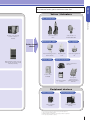
Products
Burner Controllers
Burner Interlock Module/Buner Control Module RX series Burner Interlock Module RX-L80/90 Burner Control Module RX-R40/20 Flame detectors
Advanced Ultraviolet Flame Detector AUD300C1000 Advanced Ultraviolet Flame Detector AUD500C11000 Advanced Ultraviolet Flame Detector Socket for the AUD15 Tube Unit AUD100/110
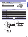
Visible Light Frame Detector AFD100A/B Visible Light Flame Detecter AFD110A Pressure Switch
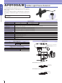
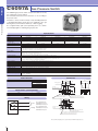
Gas Pressure Switch C6097A Igniter
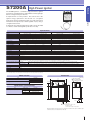
High Power Igniter S7200A Peripheral devices
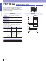
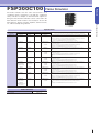
Analog Flame Meter FSP136A Flame Simulator FSP300C100 22
24
25
27
28
29
30
31
32
33
34
35
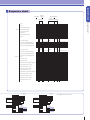
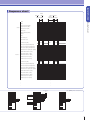
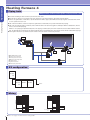
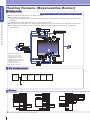
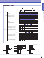
Application Examples (RX Series)
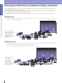
Selecting an RX Series Combustion Safety Controller
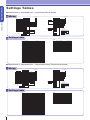
Boiler Deodorizing Furnace Small Holding Furnace Small Melting and Holding Furnace Large Melting Furnace Heating Furnace 1 Heating Furnace 2 Heating Furnace 3 Heating Furnace 4 Heating Furnace (Regenerative Burner) Settings Tables 38
40
42
44
46
48
50
52
54
56
58
60
1
2
Flame
Safeguard
System
Overview
Introduction to Flame Safeguard System
Flame Safeguard System
Component Devices
Detection of Combustion Flame
Flame Detector Types and Features
Safety Shutoff Valves
Gas Safety Shutoff Valve Flow Calculation
Ideas in Support of Industrial Furnace Safety
General Safety Code for Industrial
Combustion Furnaces: JIS B 8415: 2008
Outline of revisions to JIS B 8415 (November 2008)
Basic points for safe combustion
Concept Behind Combustion Equipment
Control and Safety
Product Line
3
Overview
Introduction to Flame Safeguard System
Flame Safeguard System
FSG
(Flame Safeguard System)
structure of
•Basic
flame safeguard system
The set of equipment used to provide safe control of burner
operation. This usually includes the flame safeguard control, the
flame detection system, all controllers, all limits and interlocks, all
fuel valves, the ignition system, the firing rate control system,
and any other auxiliary equipment.
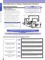
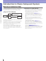
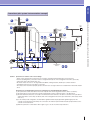
Introduction to Flame Safeguard System
The flame safeguard system limits the operation to within
safe operational ranges using limits and interlocks, and
always monitors combustion conditions by means of a flame
detector. The signal from the flame detector is converted by
burner controller into the signal required for actuators to
operate safety shutoff valves.
If some failure has occurred in the combustion equipment
resulting in an ignition failure or other burner flame failure,
the flame detector detects the abnormal condition of
combustion flame, transmits the signal to the burner
controller to close the safety shutoff valves, and prevents the
flow of fuel into the combustion chamber.
If the flame detector or burner controller has caused a
failure, the system has a safety circuit function to operate
the fuel shutoff valves or not to start the burner.
Functions of the Flame Safeguard System
•Stops the burner by automatic or manual operation.
•Starts the burner in correct sequence and monitors the
combustion flame during operation.
•Protects against abnormal temperatures or pressures.
•Controls the combustion quantity of the burner.
•Maintains the operation start standby state during burner
stop.
Combustion
control motor
burner controller
Air pressure
switch
Limit/
interlock
High limit
Controller
Air
Fuel
Exhaust
gas
Gas
pressure
switch
Main valve
Flue
Pressure control
Pilot safety
shutoff valve
Combustion
equipment
Flaw detector
Ignition transfor mer
The purpose of the FSG is to prevent an explosion.
For this purpose,
the FSG does not allow fuel to accumulate in the furnace (combustion chamber).
The FSG controls the fuel to keep the density below the explosion limit.
Cases of fuel accumulation in the furnace and corrective measures to them
• Prepurge
Residual gas remains in furnace.
Safety shutoff valve is opened before
the ignition source is activated
at the time of burner ignition.
Ventilation must be made until fuel density is decreased to the level below the explosion
limit. The ventilation time length must not be shortened even if a failure occurs.
• Burner controller, safety shutoff valve (periodical maintenance)
• Correct ignition sequence
Ignition must be made in the correct sequence. Operation will not occur if there
is an abnormality. The sequence must not be changed even in the event of a failure.
• Burner controller (start check, ignition sequence)
• Ignition timing
Burner is not ignited even though
ignition operation is tried.
Burner has suddenly experienced
a flame failure due to some cause
during operation.
Burner is experiencing incomplete
combustion due to an inappropriate
fuel/air ratio.
4
Shutoff must be made before the density increases to the explosion limit.
Ignition time length must not become longer even in the event of a failure.
• Flame detector, burner controller (ignition sequence)
• Flame detection, reliable fuel shutoff, and flame response
Flame failure must be reliably detected, and the fuel must be shut off before
its density increases to the explosion limit.
• Flame detector, burner controller (flame response), safety shutoff valve
• Reliable limit and interlock
Combustion conditions must be continuously secured by limits.
• Gas pressure switch / air switch (periodical maintenance)
Overview
Introduction to Flame Safeguard System
Component Devices
• Limit •
• Burner controller •
2. Responds to the temperatures, liquid levels and pressures.
Industrial furnaces may have the problem of abnormally
high temperature while boilers may have the problem of low
water level or abnormally high pressure.
• Interlock •
1. Checks that the conditions are right to start combustion.
2. Checks that the conditions are right to continue
combustion.
3. A start interlock is used to check the damper or burner
position (high or low fire), fuel pressure, oil pre-heating
temperature, and fuel shutoff valve closure.
4. A running interlock is used for fuel pressure, combustion air
pressure, or draft.
When the interlock for fuel pressure or combustion air
pressure is operated, the safety shutoff is operated for
lockout.
•
Flame detector
•
1. Detects the flame and sends a converted electric signal to
the burner controller.
2. Flame detectors for industrial furnaces use the light
(ultraviolet rays, etc.) emitted from the burner flame.
Burner controller has very important functions for the
safety of burner operation and flame monitoring, and is
designed as a failsafe system.
Introduction to Flame Safeguard System
1. Has the function of limiting operation so that it is within the
safe operational ranges. Even when a control is out of order
due to the malfunction of a controller, resulting in a
continuing uncontrolled operational state, the limit controller
can function to limit operation to within the safe ranges,
ensuring safety. The limit controllers provided for safety
must not be used mistakenly with other controllers. They
must be clearly distinguished, selected and independently
installed to ensure safety. The limit controllers are selected
for reliable operation rather than for high accuracy.
The extent to which combustion equipment can be
controlled is dependent upon the safety provided by the
limit controllers.
1. Detects that stable flame exists.
2. Starts the motor, fan, ignition and fuel valve in the correct
sequence and at the correct time to ensure safe operation.
(1) Supplies power to the devices in the correct sequence
and at the correct time.
(2) Shuts off the power supply given to the devices in a
pre-determined sequence upon ignition failure, flame
failure, or cessation of combustion.
3. Checks itself.
(1) Checks its component parts every time an operation
starts or power is applied.
(2) Prevents burner ignition when a false flame signal
exists.
4. Failsafe design is incorporated.
(1) Failsafe design is incorporated in the start check circuit
ensuring no occurrence of checking error.
(2) Ignition sequence is never performed out of order.
(3) There is no occurrence of a timing error that would
result in a dangerous instruction. For example, the
required period for prepurging gas from the furnace
before ignition does not become shorter. The ignition
spark timing does not become longer.
• Safety shutoff valve •
1. There are ON/OFF, high/low and proportional types.
2. Delayed operation is available for oil, and slow-opening
operation is available for gas.
• Temperature and Pressure Controllers •
1. Operates to keep the control at a set point.
2. Includes the temperature controllers, and pressure
controllers or start/stop switches.
5
Overview
Introduction to Flame Safeguard System
Detection of Combustion Flame
In the Flame Safeguard System, the detection of combustion flame
has a very important role. The accurate detection of a flame is
accomplished by fully utilizing the physical properties of flame.
Introduction to Flame Safeguard System
•Types of flame detectors
Optical
type
Flame
detector
Insertion
type
For the detection of a combustion flame, a flame detector that
effectively utilizes the nature of the flame is necessary. When
utilizing any flame detector, it is essential to select a detector
which is appropriate for the nature of the flame.
• Ultraviolet flame detector
Ultraviolet flame detector
Visible light flame detector
Infrared rays flame detector (PbS cell)
Flame rod
Thermocouple
The detection methods of combustion flames are categorized into
two types:optical and insertion.
The optical type consists of a sensor element that indirectly detects
the brightness in the furnace and flame color or its wavelength,
and the electronic circuits for signal conversion and amplifier.
Since the detection is indirect, care must be taken so as not to
receive any influence of external light.
Since the insertion type is used by directly inserting the sensor
element into the flame, the flame temperature, length, and state
can be detected, and therefore the detection is highly reliable.
However, care must be taken with regard to sensor responsiveness
and mounting position.
6
•Selection of a flame detector
Since there are few restrictions in its mounting location, this
detector is widely used for various applications. Care must be
taken in its use so as not to mistakenly detect the spark of an
igniter.
In the case of a continuously operating burner in which the
flame does not stop for more than 24 hours, the use of a
continuously self-checking type of flame detector is required to
ensure failsafe operation.
• Visible light flame detector
This detector is used for a compact oil-fired burner. The gas
blue flame cannot be detected. When a boiler or agricultural
drying furnace is installed outdoors, special care must be taken
so as not to mistakenly detect sunlight.
• Flame rod
A flame rod utilizes the electrical conductivity of flame. In order
to avoid a detection error in the event of a short-circuit between
the sensor signal and the ground, the rectification function is
utilized to ensure safety.
Overview
Introduction to Flame Safeguard System
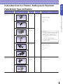
Flame Detector Types and Features
Detectors
Ultraviolet phototubes
(UV sensors)
Model/appearance
AUD300C1000 Series
Flame property Applicable combustion
Ultraviolet light
Batch operation or continuous operation
Introduction to Flame Safeguard System
185–245 nm
Gas
Oil
Main uses
Pilot burner monitoring
Main burner monitoring
Industrial furnaces
Plants
AUD500C11000 Series
Boilers
C7076A
Ultraviolet light
185–270 nm
[Reference]
Continuous operation equipment means:
Combustion continues for at least 24 hours
Batch operation equipment means:
C7076D
Combustion starts and stops at least once
every 24 hours
(
AUD100+AUD15
Note: Flame detectors designed for
continuous operation can also be used
for batch operation.
)
For batch operation
Ultraviolet light
185–245 nm
Pilot burner monitoring
Main burner monitoring
Industrial furnaces
Boilers
AUD110+AUD15
Photo diodes
(Visible light flame detectors)
AFD100
Light
400–800 nm
Oil
For batch operation
Small oil-fired boilers
AFD110
7
Overview
Introduction to Flame Safeguard System
Safety Shutoff Valves
•Safety technology related to safety shutoff valves
Source: Japan Gas Association, “Safety Technology Indices for Industrial Gas Combustion Equipment,” January 2009
Introduction to Flame Safeguard System
The basis of gas combustion equipment safety is the ability to shut off the gas supply immediately when an abnormal or dangerous state
occurs. The safety shutoff valve is the key safety device for immediate shutoff of the gas supply to the overall equipment or to an independent
zone when a hazardous state arises, such as a combustion issue like ignition failure or flame failure, or an abnormal rise in the temperature of
the heating unit, or when the gas or air pressure falls outside the preset range. As a rule, two safety shutoff valves are installed in series in the
event that one valve is not able to completely shut off the gas due some problem with the valve.
•Conditions requiring installation
Safety shutoff valves must be installed where they can immediately shut off the gas supply to the overall equipment or to an independent
combustion zone when a hazardous state arises, with the exception of cases where the operator is able to continuously monitor the heating
unit situation and immediately shut off the gas in the event of danger, such as when workmen are using hand-held acetylene torches near the
gas pipeline.
•Safety shutoff valve
Safety shutoff valves must be able to shut completely and automatically within 1 second after the supply of electricity or air pressure stops,
must be able to sufficiently withstand the usage pressure, and also must comply with the relevant standards.
Specifically, JIS B 8415 (General Safety Code for Industrial Combustion Furnaces) states that it is preferable for a fuel switch valve for a
regenerative burner, such as a high-performance industrial furnace, that is being used as a shutoff valve to be given a minimum of two million
operation test cycles as a durability test using the method prescribed in ISO 23550.
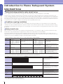
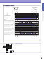
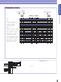
Leakage Standards for Safety Shutoff Valves: List of Safety Shutoff Valve Leakage Standards
Standard
EN161
Europe
UL429
USA
External leakage
Standard bore
DN < 10
20 cm3/h or less
10 ≤ DN ≤ 25
40 cm3/h or less
25 < DN ≤ 80
60 cm3/h or less
80 < DN ≤ 150 60 cm3/h or less
150 < DN
60 cm3/h or less
200 cm3/h or less
JIS B 2151
Japan *1
30 cm3/h or less
ISO 23551
Standard bore
DN < 10
10 ≤ DN ≤ 25
25 < DN ≤ 80
80 < DN ≤ 150
150 < DN ≤ 250
Test methods
Measure at the burette or water column gauge
after applying 60 mm of H2O and a pressure of
1.5 times the maximum usage pressure from
the inlet and outlet.
1.5 times the maximum usage pressure for
those with 350 mm of H2O or greater.
Measure with the leakage detector at 4.2 kPa as
well as 0.5 kPa of air pressure from the inlet.
20 cm3/h or less
40 cm3/h or less
60 cm3/h or less
60 cm3/h or less
60 cm3/h or less
Internal leakage
Standard bore
20 cm3/h or less
DN < 10
10 ≤ DN ≤ 25
40 cm3/h or less
60 cm3/h or less
25 < DN ≤ 80
80 < DN ≤ 150 100 cm3/h or less
150 < DN
150 cm3/h or less
235 cm3/h or less (when the internal
diameter is greater than 11/2 B, add an
extra 235 cm3/h for each B)
• 30 cm3/h or less (for appliance valves)
• 300 cm3/h or less (for non-appliance valves)
After carrying out an internal leakage test at
0.6 kPa, repeat the test using pressures of
either 1.5 times the maximum usage pressure
or 15 kPa, whichever is higher.
However, those using gas at 11.2 kPa or 14.8
kPa should be tested at a minimum of 22 kPa.
Standard bore
DN < 10
10 ≤ DN ≤ 25
25 < DN ≤ 80
80 < DN ≤ 150
150 < DN ≤ 250
20 cm3/h or less
40 cm3/h or less
60 cm3/h or less
100 cm3/h or less
150 cm3/h or less
Test methods
Measure at the burette or water column gauge
after applying 60 mm of H2O and a pressure of
1.5 times the maximum usage pressure from
the inlet and outlet.
• Test at 175 mm of H2O and again at 1.5 times the
maximum usage pressure (but at least 350 mm of H2O).
• Measure
• Measure the pressure difference at a pressure gauge
upstream from the valve.
Measure at the leakage detector at 4.2 kPa as
well as 0.5 kPa air pressure from the inlet.
After carrying out an internal leakage test at
0.6 kPa, repeat the test using pressures of
either 1.5 times the maximum usage pressure
or 15 kPa, whichever is higher.
However, those using gas at 11.2 kPa or 14.8
kPa should be tested at a minimum of 22 kPa.
*1. For cases of connection to a gas pipe with an outer diameter of 35 mm or less, for gas burning appliance automatic valves used in combustion equipment that uses city gas or liquefied petroleum gas at a gas pressure of 3.3 kPa or less.
European Safety Shutoff Valve Standard (EN161 Group 2): Excerpted summary by Azbil Corp.
Item
Leakage
Valve closure ability
Durability
Performance
External leakage
20 cm3/h or less
40 cm3/h or less
60 cm3/h or less
60 cm3/h or less
60 cm3/h or less
Size
DN < 10
10 ≤ DN ≤ 25
25 < DN ≤ 80
80 < DN ≤ 150
150 < DN
Test methods
Measure internal leakage after applying pressure from
the inlet, and external leakage from the inlet and outlet,
using 60 mm of H2O and a pressure of 1.5 times the
maximum usage pressure.
Internal leakage
20 cm3/h or less
40 cm3/h or less
60 cm3/h or less
100 cm3/h or less
150 cm3/h or less
Applied pressure
Class A: 1500 mm — H2O
Class B: 500 mm — H2O
Class C: 100 mm — H2O
Done with the pressure at the maximum allowable
pressure, the flow rate at 10 % or less of the rating, the
voltage at 85 % at –15 °C, 85 % and 110 % (half each)
at 20 °C, and 110 % at 60 °C.
Must meet the above internal leakage standards when pressure is applied from the outlet.
Size
1 or less
11/ 4–3
-15 °C
20 °C
60 °C
Total
25,000 cycles 125,000 cycles 50,000 cycles 200,000 cycles
25,000 cycles 50,000 cycles 25,000 cycles 100,000 cycles
Must meet the operation, leakage, and valve closure pressures in the above test.
Flow
Resistance to gas
Must be within 95 % of specification.
With n-pentane must be within ±15 % of the volume change ratio.
Open time
(slow open)
Must be ±20 % of manufacturer’s specification.
Strength
(torque: kgf·cm)
Size
Bending torque
Twisting torque
3/
8
7
3.5
1/
2
10.5
5
3/
4
22.5
8.5
Group division
Group 1: Shipped in the bracket, no force applied during piping work.
Group 2: Installed inside or outside the bracket, supported only by the pipe.
8
1
34
12.5
11/ 4
47.5
16
11/ 2
61
20
2
110
25
21/ 2
160
32.5
3
240
40
Converted to 15 °C atmospheric pressure
Measure at 40 °C after steeping in 23 °C n-pentane for
72 hours and then air-drying for 72 hours.
Measure the time taken to reach 80 % of the
specification flow rate at 110 % of rated voltage at 60 °C
and 85 % of rated voltage at -15 °C.
For each, apply torque for 10 seconds and check for
internal and external leakage.
Overview
Usage by class (following EN 746-2)
Combustion capacity
Less than 120 kW (100,000 kcal/h)
When not monitored by operator
Class B: 2 valves
Less than 120–600 kW (100,000–500,000 kcal/h)
Less than 600–1,200 kW (500,000–1,000,000 kcal/h)
Class A: 1 valve
Class B: 2 valves
Class A: 2 valves
Class A: 2 valves
1,200 kW (1,000,000 kcal/h) or above
Class A: 2 valves
Class A: 2 valves
Introduction to Flame Safeguard System
When monitored by operator
Class A: 1 valve
Closed position indicator switch
In ISO 23551-1 (Safety and control for gas burner and gas burning appliances – Particular requirements – Part 1: Automatic valves), the
closed position indicator switch is defined as the switch attached to the valve that indicates that the closing part is in the closed position.
The following are specifically required.
Structure
Must not interfere with normal valve operation
The adjustment mechanism must seal it so that it can be seen that no adjustments have been made that the manufacturer did not intend.
No amount of drift in the adjustment switches or driving mechanism may interfere with normal valve operation.
Performance
The switch is required to indicate the closed position in both of the following situations.
When the flow is 10 % or less of the fully open flow at the same differential pressure.
When the closing part is positioned within 1 mm of the closed position.
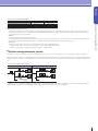
•Position during automatic ignition
Normally two safety shutoff valves should be installed separately in series on the fuel supply pipes for the pilot burner and the main burner.
During synchronous ignition or extinguishing, as shown below, the safety shutoff valves for each burner form one layer, and by adding another
safety shutoff valve in the zone, it is possible to have a double valve structure. However, this does not allow ignition or extinction of one burner
only.
Pipe Layout for Double Shutoff Valves
Synchronous ignition (extinction)
Non-synchronous ignition (extinction)
Synchronous
operation
In addition, for non-synchronous ignition and extinction, two safety shutoff valves need to be installed for each burner, using double shutoff.
Unlike synchronous ignition, this configuration allows ignition and extinction of each burner separately.
9
Overview
Introduction to Flame Safeguard System
Gas Safety Shutoff Valve Flow Calculation
CV is normally used as a coefficient for showing the valve flow-through rate (capacity), but safety shutoff valves often show the flow rate and CV
at a specific differential pressure or specific gravity determined by the gas.
Introduction to Flame Safeguard System
Example:
The following table shows the CV and flow rates for a GV-A high-performance industrial-use gas double electromagnetic valve (with two
connected in series). The flow rate values are at 15 °C and 101.325 kPa.
Model
GV-A100
Connection
Flow rate m3/h
bore
differential pressure 250 Pa
Specific gravity 0.65
Specific gravity 1.53
8.5
5.6
5.8
10.9
16.4
7.1
10.7
7.5
11.2
25A (Rp 1)
18.6
12.1
12.7
25A (Rp 1)
32A (Rp 1 1/ 4)
32.8
21.4
22.4
40A (Rp 1 1/ 2)
41.1
45.6
26.8
29.7
28.1
31.2
10A (Rp 3/ 8)
15A (Rp 1/ 2)
20A (Rp 3/ 4)
GV-A200
GV-A300
CV
50A (Rp 2)
46.4
30.3
31.7
40A (Rp 11/ 2)
65.9
43.0
45.0
50A (Rp 2)
65A (Rp 2 1/ 2)
71.4
74.3
46.5
48.4
48.8
50.8
CV and flow rate can be read from this table only if the differential pressure is 250 Pa and the gas type is natural gas 13A (specific gravity:
0.65) or propane gas (specific gravity: 1.53).
Differential pressure (kPa)
240
340 250
350
365
225
232
10
120
125
110
115
The following graph shows the relationship between flow rate and differential pressure when natural gas 13A is flowing through a GV-A.
The flow rate values are at 15 °C and 101.325 kPa.
110GV-A100 + 10A flange
115GV-A100 + 15A flange
120GV-A100 + 20A flange
125GV-A100 + 25A flange
225GV-A200 + 25A flange
232GV-A200 + 32A flange
240GV-A200 + 40A flange
250GV-A200 + 50A flange
340GV-A300 + 40A flange
350GV-A300 + 50A flange
365GV-A300 + 65A flange
1
0.1
1
2
3
4 5 6
10
20
30 40 50 60
100
200
300
1000
Flow rate (m /h)
3
This graph makes it possible to find the flow rate for any given differential pressure, for natural gas 13A only.
10
Overview
The preceding table had a limited range of differential pressures and gas types,
but it is possible to find the flow rate under other conditions by using the following calculation.
Q = K × (∆P/ρ)
(1)
Q : Flow rate (m3/h)
K : Proportional constant
∆P : Differential pressure (Pa)
ρ : Specific gravity
Introduction to Flame Safeguard System
A. When the differential pressure is 250 Pa or greater, use the following modification of formula (1) to find the flow rate:
Q=(Flow rate table value) × ((defferential pressure)/250)
Ex.: Find the flow rate for GV-A200 (bore: 1½), with a differential pressure of 980 Pa and natural gas 13A.
According to the above table, the flow rate is 34.7 m3/h when the differential pressure is 250 Pa, so the flow rate is:
Q=34.7× (980/250)=68.7 m3/h
B. When the specific gravity is not 0.65, use the following modification of formula (1) to find the flow rate.
Q = (Flow rate table value) × (0.65/(specific gravity))
Ex.: Find the flow rate for GV-A200 (bore: 1½), with a differential pressure of 250 Pa and 6C gas (manufactured gas B).
If the specific gravity of 6C is 0.55, the flow rate is:
Q=34.7× (0.65/0.55)=37.7 m3/h
C. When the differential pressure ∆P ≠ 250 Pa and the specific gravity ρ ≠ 0.65, use the following modification of formula (1) to find the flow rate.
Flow rate Q = Flow rate table value× ((defferential pressure)/250×0.65/(specific gravity)
11
Overview
Ideas in Support of Industrial Furnace Safety
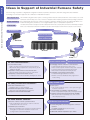
Ideas in Support of Industrial Furnace Safety
For a wide range of operation configurations and ignition methods, we provide total solutions, from flame safeguard control and flame
monitoring to fuel shutoff, in support of safe combustion in industrial incinerators.
Flame safeguard controls
Our new flame safeguard control system, consisting of burner interlock modules and burner control modules, uses a new
architecture to allow safety, ease of use, and ease of adjustment when installing equipment and responding to problems.
Flame monitoring
Our compact flame detectors for continuous operation combustion equipment can be used without problems even
for burners having many restrictions, such as tight installation space or temperature requirements.
Fuel shutoff
The advanced-function double-seated gas shutoff valve made by Elster Kromschroder, a company with a proven track record with European industrial
burners, uses a modular structure that allows for installation in tight spaces around fuel pipes or burners when there are space or other restrictions.
Flame detector
Safety shutoff valve
Burner interlock module
&
Burner control module
AUD Series
GV-A
Limit/interlock
Igniter
RX Series
C6097
For fuel-safe construction…
Look for intrinsic safety
• Carry out safety measures based on risk assessment
• Mechanical safety/comprehensive safety indices (JIS B
9700-2/JIS B 9702)
Separation of safety functions and control functions
• Review software interlocks by means of control PLC
Complexity of safety instrumentation circuits
• Complexity increases due to redundancy and diagnostic circuits.
For safety shutoff valve installation…
Two valves installed in series
• Installation space is often restricted
Installation and replacement of shutoff valves
• Removing surrounding piping is bothersome
Compliance with international standards
S7200
Burner interlock module
12
Selection of devices suited to operation method
• Self-checking flame detectors are used for continuous
combustion of 24 hours or more
Installation space restrictions
• Numerous installation space restrictions around the burner
Investigation is required for installation location and
cooling measures around hot burners
Burner control module
Packaging of burner combustion control functions
• Shortened design verification time for safety circuits
• Reduced circuit design and verification for safety circuit construction
• Selection and setting of pre-incorporated safety functions
• Burner interlock module (interlock monitoring function)
Packaging of panel safety instrumentation
• Shortened wiring/installation/check times
• Module connectors distribute safety signals and
reduce wiring
Safety shutoff valve
For flame detector selection…
&
Saves space
• Two can be installed in series to save space through
modular construction
Shortened time for installation and replacement
• Can be easily installed or replaced by connecting the flanges
Products meet European and international standards
• EN 161/ISO 23551-1 (durability tests, valve closure
switch display function)
AUD Series flame detector
Self-checking flame sensor is designed for continuous
operation
• AUD300, AUD500 advanced UV sensors
Installs in small spaces
Withstands ambient temperatures up to 120 °C
Overview
General Safety Code for Industrial Combustion Furnaces: JIS B 8415: 2008
Outline of revisions to JIS B 8415 (November 2008)
Safety methods through risk assessment created as ISO standard and introduced to Japan
ISO 12100
JIS B 9700
Industrial Safety and Health Act Revision
Background
(Basic concepts, general
regulations for design)
(Basic concepts for safety
and design of machinery)
(Industrial Safety and Health Act)
Position
JIS B 9700-1 Machinery Safety: Equipment regulations defined in
basic concepts and general rules (Type C)
Positioning in standards systems that also meet ISO standards
Scope
Heating equipment using gas or liquid fuel (industrial furnaces, etc.)
Metallurgy, metal processing plants
Glass production, ceramics, cement production plants, etc.
JIS B 8415
(2008)
Revised Japan Gas Association
(2009)
EN 746-2 (Europe)
(1997)
NFPA 86 (USA)
(2007)
General safety code
for industrial
combustion furnaces
Safety technology indices
for industrial gas
combustion equipment
Industrial thermoprocessing
equipment, Part 2.
Safety requirements for combustion
and fuel handling system
Standard for Ovens
and Furnaces
Intrinsic safety design
based on risk assessment
prohibition of software
interlocks by general-use PLC
Aiming for fail-safe and foolproof control
and operation circuits
(prohibition of construction of combustion
safety interlocks using only general-use PLC)
Intrinsic safety design
based on risk assessment
(EN 292)
Installed in series
in holding circuit
for safety shutoff valve
Must be directly connected
to the main control terminals
of the flame monitor relay
or flame safeguard control system
Should immediately shut off
for safety
when interlocks operate.
Interlock setting values
must be shown in writing
Must be connected directly
Installation requirements for safety
shutoff valves (for main burner, pilot burner)
Two installed in series
(shutoff within 1 second)
Two installed in series
(shutoff within 1 second)
Two installed in series
Two installed in series
Flame monitoring equipment for
industrial furnaces that burn
continuously for 24 or more hours *1
Self-check
at least once a day
Self-check
at least once a day
Continuous combustion operation uses
a self-checking type or regular checks
Continuous combustion operation uses
a self-checking type or regular checks
Individual monitoring
Individual monitoring
Individual monitoring
Individual monitoring
Within 4 seconds
(Flame failure safety time: within 5 seconds)
Within 4 seconds *2
(shutoff within 5 seconds)
Within 3 seconds
Within 4 seconds
Must not make shared use of
a temperature controller
used for control
or the controller’s
temperature detector.
Must not make shared
use of a temperature controller
used for control
or the controller’s
temperature detector.
Must not make shared
use of a temperature controller
used for control
or the controller’s
temperature detector.
Must not make shared
use of a temperature controller
used for control.
Excess temperature limit interlock
requires temperature display
and manual reset.
Safety shutoff
and lockout
Check request at start
-
Check request at start
Combustion air detector
must be checked
when burner is started,
and if there is an abnormality
the burner must not be started.
Combustion air detector
must be checked
when burner is started,
and if there is an abnormality
the burner must not be started.
Combustion air detector
must be checked
when burner is started,
and if there is an abnormality
the burner must not be started.
-
At least 5 times
At least 5 times
Completely 5 times
At least 4 times
Airflow rate at prepurge
At least 50 % of peak
At least 50 % of peak
At least 25 % of peak
At least 25 % of peak
Burner flame amount at ignition
Forced low fire ignition
Low fire ignition/extinction
-
-
Standard
Items
Control and operation circuits
Interlocks
Individual monitoring of pilot and
main burner flames
Flame failure response time
in flame monitoring equipment
Installation of
overheat protectors inside furnace
False flame operation
during start check
Pre-operation check of
combustion air pressure
Prepurge air flow (number of changes of air)
(
(
Pilot burner ignition timing
Within 10 seconds
Within 10 seconds
Main burner ignition timing
Within 5 seconds
Within 5 seconds
350 kW or less
Direct spark ignition
(direct ignition)
Installation of seismic detector equipment
350 kW or less
Under 58 kW within 5 seconds
Under 117 kW within 3 seconds
350 kW or less within 2 seconds
Installed as necessary
(for seismic intensity 6 or higher)
Installed as necessary
(for seismic intensity 6 or higher)
Within 5 seconds: 70 kW or less
Within 3 seconds: over 70 kW
Within 5 seconds: 70 kW or less
Within 3 seconds: over 70 kW
350 kW or less
70 kW or less: within 5 seconds
70 kW-350 kW: within 3 seconds
-
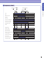
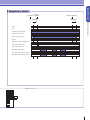
General Safety Code for Industrial Combustion Furnaces: JIS B 8415: 2008
Coordination with Western standards
European EN 746, USA NFPA 86
Standards supporting new technology
Support for high-function industrial furnaces (regenerative burners, etc.)
Design requirements to minimize fire
and explosion risks
requires use of PLC
with safety protection equipment
(
(
Within 15 seconds
Within 15 seconds
-
-
*1. The flame monitoring equipment refers to a flame detector and a flame safety controller (burner controller). *2. If there are other regulations that specify the flame failure response time, they should be followed.
13
Overview
General Safety Code for Industrial Combustion Furnaces: JIS B 8415: 2008
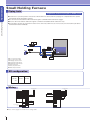
Basic points for safe combustion
1 Proper purging (5 times furnace capacity)
2 The combustion air detector (air pressure switch) must
7 Safety shutoff and lockouts for ignition failure and flame failure.
be checked when the burner starts up, and if there is
an abnormality, the burner must not be started.
The load on the fuel shutoff valve, etc. must be
directly connected to the burner controller (the
flame safeguard control system).
The limit/interlock is configured to directly cut off the
power supply to the combustion shutoff valve load.
The start check circuit must operate properly at
start-up.
There must be no manual operation or bypass
circuit for any load.
(Select a continuous operation burner controller or flame detector
for equipment that is operated continuously for at least 24 hours.)
9 The main shutoff valve and pilot shutoff valve must both use
double shutoffs.
10 An excess temperature limit interlock must be installed
separately from the temperature controller for control use
and the controller’s temperature detector.
11 Individual monitoring of the pilot burner flame and the main burner
flame
(For the continuous pilot method or the intermittent pilot method,
separate flame monitoring equipment is required for the main burner.)
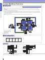
General Safety Code for Industrial Combustion Furnaces: JIS B 8415: 2008
3
4
5
6
8 Correct selection of burner controller and flame detector.
These items are also required by the European and American standards.
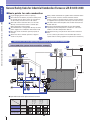
Interrupted pilot system instrumentation example
4
Seismic sensor
limit
Limit
Temperature
controller
SDC35
7
Ignition
command
Alarm
4
Limit
8
Burner interlock module
Burner control module
Limit
10
Excess temperature limit
Flame shutter
5
Ignition transformer
Pilot valve
Main valve
3
Interlock
Exhaust gas
4
3
8
Pilot safety
shutoff valve
1 2
Air pressure
switch
Pressure
(C6097A) gauge
PS
Blower
Flue
9
PG
Main safety
shutoff valve
Gas pressure
Pressure
switch
gauge
C6097A
PS
Fuel
Exhaust damper
interlock
Advanced
UV sensor
AUD300C
Gas
pressure
switch
C6097A
Pressure
gauge
PS
PG
PG
6
M
Igniter
S7200
9
Continuous pilot
Pilot burner
Main burner
Intermittent pilot
Pilot burner
Main burner
Interrupted pilot
Pilot burner
Main burner
Ignite
Control
extinction
Control
ignition
Control
ignition
Control
extinction
Start-up
ignition
Operation method for pilot and main burners
: Prepurge
14
Overview
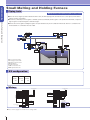
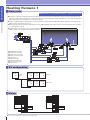
Intermittent pilot system instrumentation example
7
Ignition
command
4
Alarm
Limit
Flame shutter
5
Pilot valve
Interlock
Seismic
sensor
limit
4
Ignition transformer
Temperature
controller
SDC35
4
4
8 11
General Safety Code for Industrial Combustion Furnaces: JIS B 8415: 2008
8 11
Burner interlock module
Burner control module
Limit
10
Limit
Excess
temperature
limit
Advanced UV sensor
for main burner
AUD300C
Exhaust
gas
Exhaust
damper
interlock
Flue
3
Pilot safety
shutoff valve
1 2
Air pressure
switch
Pressure
(C6097A) gauge
PS
Blower
Caution:
M
Igniter
S7200
Main
Gas pressure
safety shutoff valve switch Pressure
Gas pressure
switch
Pressure
C6097A
gauge
PS
Fuel
9
PG
PG
6
C6097A
gauge
PS
PG
Advanced UV sensor
for pilot burner
AUD300C
8 11
9
Precautions for burner control circuit design
Safety control and operation circuits must use an intrinsic safety design method based on risk assessment.
Interlock (including limits) connections must be configured to directly cut off the load (ignition transformer, pilot safety
shutoff valve, main safety shutoff valve, etc.).
All shutoff contacts are to be on the ungrounded. In addition, leakage breakers, double-pole contacts and other
anti-leakage measures are to be taken as necessary.
The safety control circuit must promptly produce an alarm such as a light or buzzer as needed when an abnormal situation
arises.
Precautions for instrumentation and circuit configuration for the intermittent pilot method
(1) The pilot burner and the main burner must have separate flame monitoring (flame detectors, burner controllers).
(2) The flame detector for the main burner must be installed where it will not detect the flame of the pilot burner.
(3) The limit and interlock must be connected to the limit and interlock terminals of the burner controllers for the pilot burner
and the main burner so that they can directly shut off the load (ignition transformer, pilot shutoff valve, main safety shutoff
valve, etc.).
(4) For the startup circuit configuration, the main burner ignition enabled output (pilot flame ignition signal) from the
controller for the pilot burner must always be connected to the interlock input terminal and start-up input terminal on the
controller for the main burner.
(5) When the pilot burner or main burner fails to ignite or goes out, the circuit must stop all burners.
15
Overview
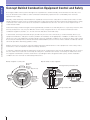
Concept Behind Combustion Equipment Control and Safety
Even highly reliable control systems with high levels of performance and functionality cannot eliminate the risk of fire, since
they can fail and become unable to control combustion. Unfortunately, improvements in controllability have not meant
improvements in safety.
Concept Behind Combustion Equipment Control and Safety
Normally, control and safety instrumentation are separated, so that even if the safety device is relatively inaccurate, one with
reliable operation must be used. The relationship between safety and control must allow control to be performed where safety
is assured, so the control zone must be an area that is included within the safe zone. This zone is where improvements in
control must be made.
Control and safety tend to be thought of as being handled by control devices and safety devices, respectively. However, while
this may usually be the case, they are difficult to achieve solely using these devices. The structure and function of the
combustion equipment, facilities, etc., are also elements that affect control and safety.
In other words, achieving control and safety is possible only once the three elements of (1) control and safety devices, (2)
equipment and facilities, and (3) the location (conditions of installation) are all appropriate. In addition, it is difficult to ensure
safety in the case of all equipment or facilities failing or when the installation conditions are no longer met. When safety cannot
be assured, we naturally wish to eliminate all failures and breakdowns, but even if all scenarios could be considered, it would
still not be possible to absolutely guarantee safety.
With this in mind, it is necessary to carry out regular inspections and maintenance of the equipment to ensure safety. That is,
maintenance is also an important component of safety assurance.
In summary, combustion equipment and facilities are objects for control, but they also must be fundamentally safe. To achieve
this, the control zone needs to be encircled by the safety zone, and that in turn must be encircled by the maintenance zone.
The equipment and facilities, and the control devices (including the flame safeguard control system), and the installation
conditions are each elements of control/safety/maintenance.
Safety configuration of control system
Controllers
Specific example of safety configuration
Controllers
Limits
Sensors
Actuators
(valves, damper motors)
Power (high electric potential side), HOT
Limit
Safety zone
Maintenance zone
Burner
controller
Safety valves
Burners
Valve trains
Dampers
Safety
zone
ON/OFF control
Main valve
Piping
Ventilation
Flues
Control zone
Equipment
Pilot valve
Installation
location
Ignition transformer
Safety zone
Fuel
Shutoff
valve
Control
zone
Burner
Control zone
Power (ground side), GND
16
Control
valve
Overview
Memo
Concept Behind Combustion Equipment Control and Safety
17
Flame detectors
Burner controllers
Continuous operation and intermittent operation systems
Continuous operation and intermittent operation systems
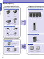
Product Line
Overview
Product Line
Advanced ultraviolet flame detector
AUD300
AUD500
Burner interlock module and
burner control module
RX-L and RX-R
Ultraviolet flame detector *1
C7076A
Flame
detection
signal
C7076D
Intermittent operation systems
Advanced ultraviolet flame detector and socket
Advanced UV relay
AUD100/110 + AUD15
AUR350
Intermittent operation systems
Visible light frame detector
AFD100
AFD110
Limit / Interlock switches
Flame relay
Gas pressure switches
FRS100
Gas pressure switch
Protect relays
C6097
Limit/
interlock
signal
Eathquake sensing switches
Protect relay
Earthquake sensing switch
V-725
18
VBC7000
R4424
(for AFD100/110)
R4440
(for AFD100/110)
Overview
For detailed specifications, or to learn whether a product is available
in a particular country, please contact our sales staff.
Valves / Actuators
Gas shutt-off valves
Product Line
Dynamic self-checking
burner controller
Solenoid valve *2
Shut-off valve *3
GV-A
MAX808/5000/7000
AUR450
Motorized gas valves
Gas regulators
Safety shutoff/
control
FSG motorized gas valve
Butterfly valve
Pressure regulator *4
CCM21/CCV20
V51E
RV
Control motors
Ignition transformers
MAX SAFETY multi protectoglo
with UV tube diagnostic circuit
Ignition transformer
R4332B (for C7076)
ATN110-A
Control motor
ECM3000
High power igniter
Flameproof
explosion-proof
ignition transformer
S7200
APN4709
Peripheral devices
Flame simulators
Analog flame meters
Flame simulator
Analog flame meter
FSP300
FSP136
*1. C7076A and C7076D are products of Honeywell International Inc.
*2. GV-A is a product of Elster GmbH.
*3. MAX808, MAX5000 and MAX7000 are products of Maxon Corporation.
*4. RV is a product of Maxitrol Company.
19
20
Flame
Safeguard
System
Products
Burner Controllers
Flame detectors
Pressure Switch
Igniter
Peripheral devices
For detailed specifications, or to learn whether a product is
available in a particular country, please contact our sales staff.
: This product is certified as complying with CE marking for use in Europe.
: This product is certified as complying with a U.S. product safety standard.
: This product is certified as complying with a Canadian product safety standard.
: This product is certified as complying with a U.S. product safety standard.
21
Products
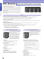
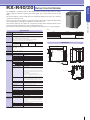
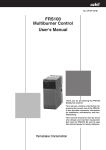
RX Series
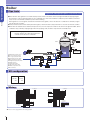
Burner Interlock Module/Buner Control Module
Burner Controllers
The RX Series represents the next generation of combustion safety
controllers for burners in industrial furnaces.
The burner interlock module (RX-L) and burner control module (RX-R)
combine to provide a variety of interlock monitoring and ignition methods.
It is possible to set the interlock monitoring timing or change the ignition
method settings by just selecting the preprogrammed safety functions
using the PC loader.
Additionally, for flame detection the RX series supports the advanced UV
sensor for continuous operation and UV sensor for batch operation, as
well as flame rods.
Features
Provides combustion safety to meet the specifications of the combustion equipment
Safety features are tailored to equipment specifications by means of the modular structure and wide range of selectable functions.
Provides a variety of preinstalled safety functions, reducing the time spent on safety circuit review and validation.
Functions can be selected and executed via the PC loader, without acquiring or creating special software.
Conservation of space and wiring
Side connectors between modules carry safety signals such as shutoff commands, eliminating the need for external wiring or relays, saving
wiring and space.
Maintenance support functions
An operation log (number of starts, operating time, alarm history, etc.) is kept automatically without the need for any special settings.
Status can be checked as necessary by connecting the PC loader.
Various monitor outputs tailored to the structure of the combustion equipment are implemented, aiding in understanding the
maintenance/troubleshooting situation and in determining the cause of a problem.
Product status checks: 7-segment LED display
Front panel indicators: Open collector monitor output
Remote status monitoring: RS-485 (standard feature)
Buner Interlock Module (RX-L80/90)
Buner Control Module (RX-R40/20)
The roles of the burner interlock module in
the combustion safety architecture are the
handling of burner interlock
monitoring/processing and of the purge
function. A maximum of 32 burner control
modules can be combined to easily
support multiple burner equipment.
This module is also equipped with the
ability to connect through RS-485 or
Ethernet (only RX-L90) communications,
making remote monitoring possible.
16 inputs
Individual OFF delay settings (to filter out chattering)
Function input (for batch startup, etc.)
Flame monitoring changeover for 760 °C or higher
Purge functions
Prepurge from 5 s to 60 min (32 selectable patterns)
Postpurge setting for any time length
Postpurge stop by temperature contacts
Blower output
Motor control
Displays
Status display (7-segment LED)
Status display (LED)
Monitor output
22 open collector outputs (freely assignable)
RS-485 communication output (standard feature)
Ethernet communication (only RX-L90)
The roles of the burner control module in
the combustion safety architecture are the
ignition, flame monitoring, and safety
shutoff functions. This unit can be
combined with the burner interlock module
to support a variety of combustion
equipment.
Ignition functions (for the 3 models below)
Models with selectable ignition sequences (RX-R40/20)
Interrupted pilot, intermittent or continuous pilot, direct
ignition, flame relay function (selection by PC loader)
Independent supervision model (RX-44)
For independent supervision of the pilot and main burner,
the RX-R44 and RX-R40 are used together.
Independent supervision and external relay drive model
(RX-46)
For control of high-frequency loads using time proportional
control, ON-OFF control, etc.
Direct ignition and external relay drive model (RX-R22)
For control of high-frequency loads using the direct ignition
method
Interlock input
4 inputs
Main unit displays
Status display (7-segment LED)
Status display (LED)
Monitor output
11 open collector outputs (freely assignable)
22
Burner Interlock Module/Buner Control Module
Products
RX Series
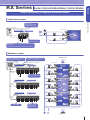
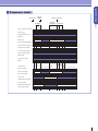
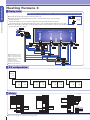
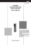
Sample configurations of single and multiburner systems
Single burner system
Burner Controllers
Status output
Open collector output
Communication output
Control panel
Monitor information (open collector info)
Burner interlock module
Flame detector
Air
Burner control module
Gas
Ignition command
Main gas solenoid valve
Igniter
Limit
Flame detection input
Safety shutoff output
Interlock
Blower
Pilot gas solenoid valve
Interlock input
16 inputs
Off-delay can be set to prevent detection of chattering
Multiburner system
Batch ignition/extinction by the burner
interlock module is possible
Control
panel
Workpiece entry
1 burner interlock module controls
16 burner control modules
Flame detector
Monitor information (open collector info)
Burner interlock module
Burner control module
Zone 1
Zone 1
Safety shutoff valve
Ignition
command
Interlock
Blower
Flame detection input
Output to safety shutoff valve
Flame detector
Zone 2
Burner interlock module
Burner control module
Zone 2
Safety shutoff valve
Ignition
command
Flame detector
Burner interlock module
Zone 3
Burner control module
Zone 3
Safety shutoff valve
Ignition
command
Zone purging
Modular structure
with side connectors
minimizes wiring
Air
Gas
Workpiece exit
23
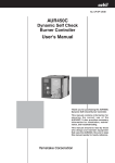
Products
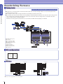
RX-L80/90
Burner Interlock Module
Specifications
Operating
Ambient temperature
-20 to +55 °C
environment
Storage temperature
Ambient humidity
-20 to +70 °C
10 to 90 % RH (without condensation)
Vibration
Shock
0 to 3.2 m/s (10 to 150 Hz for 2 h each in x, y, and z directions)
0 to 9.8 m/s2
24 Vdc
Dielectric strength
Insulation resistance
Operating life
Startup input
21.6 to 26.4 Vdc
9 W max.
• DC circuit terminals
500 Vac for 1 min
· Between 24 Vdc power terminals and input function terminals
· Between 24 Vdc power terminals and monitor output connector
· Between 24 Vdc power terminals and RX-R/RX-L control signal terminals
• AC circuit terminals
1500 Vac for 1 min or 1800 Vac for 1 s
· Between power terminals H & G and relay outputs H & G
on the one hand, and DC circuit terminals & connectors
· Between blower output terminals and DC circuit terminals & connectors
· Between control motor output terminals and DC
circuit terminals & connectors
At least 50 MΩ with a 500 Vdc megger
· Between power supply terminals H & G plus relay outputs
H & G on the one hand, and DC terminals & connectors
· Between blower output terminals and DC circuit
terminals & connectors
· Between control motor output terminals and DC terminals & connectors
7 years of continuous use, 10 years of use 8 hours per day,
or 100,000 relay contact operations (at 25 °C)
Contact input (24 Vdc, 10 mA)
*Usable with devices having contact resistance of 250 Ω or less.
Contact input (24 Vdc, 20 mA)
*Usable with devices having contact resistance of 250 Ω or less.
Reset input
Interlock input
Relay output
Blower output
(no-voltage output)
Control motor output
(no-voltageoutput)
Monitor outputs
(transistor outputs)
Communication
Communication RS-485
protocol
specifications communications
Signal level
Communication/
synchronization type
Maximum
cable length
Terminating
resistor
Transmission
speed
Ethernet comm. Protocol
RX-R
Communication
control
protocol
signal
Maximum
cable length
RX-L
Communication
control
protocol
protocol
Maximum
0.3 to 1.25 mm2 (AWG 22-18) *2
Start
IN1 to IN16
0.2 to 1.5 mm2 (AWG 28-14) *3
RS-485 comm.
Blower output
500 m
10 m
200 m
500 m
JIS C 3306, 0.75 mm2
(dia. 0.18, 30 strands min.)
Motor output
—
*1. Recommended: JCS4364 cable for light electrical instruments (twisted shielded cable for
instruments), 8 cores (4 pairs)
*2. Max. wire dia. 2 mm. Recommended crimp terminal: V1.25-3 (RAV1.25-3), made by JST Mfg. Co., Ltd.
*3. Recommended: JCS4364 cable for light electrical instruments (twisted shielded cable for
instruments), 4 cores (2 pairs)
Model Selection
Item
Buner interlock module
Model No.
RX-L80A1010010
RX-L80A101001D
Description
RS-485 communications
RS-485 + inspection certificate
RX-L90A1010010
RX-L90A101001D
RS-485 and Ethernet
RS-485 and Ethernet + inspection certificate
Optional Parts (sold separately)
Item
Model/part No.
Transistor
output connector
Description
FCN361J040-AU jack (1, solder type),
and FCN-360C040-B cover (1), both
81446847-001
RX-R/RX-L
Contact input (24 Vdc, 20 mA)
*Usable with devices having contact resistance of 250 Ω or less.
400 VA (with relay contact welding detection) *1
350 VA
control signal connector
Smart Loader Package
100 VA
Surge absorber
made by Fujitsu Components
BL3.5/7SNSW (part No. 161019)
81447402-001
made by Weidmuller (qty. 2)
For maintenance (with cables)
For maintenance (without cables)
SLP-RXMJ70
SLP-RXMJ71
SLP-RXMJ70
SLP-RXMJ71
83968019-001
22 (0.1 A max. each, 1 A max./module, 30 Vdc max.)
For function selection (with cables)
For function selection (without cables)
Dimensions
CPL
(Unit: mm)
134
RS-485-compliant
Half-duplex, start/stop synchronization
500 m
80
113
External (150 Ω, 1/2 W min.)
100
Power consumption
RX-L control
Reset
Max. cable length
50 m
38400 bps max.
MODBUS/TCP
RX-R control protocol
50 m
RX-L control protocol
5
Allowable supply voltage
Cable type
0.2 to 1.5 mm2 (AWG 28-14) *1
(10)
Rated voltage
Signal
RX-R control
(25)
Electrical
specifications
2
Table 1
32.3
Burner Controllers
The RX-L80, in combination with the burner control module (RX-R),
executes the burner interlock monitoring and prepurge functions.
There are 16 inputs for burner interlock.
In addition to interlock input, this module can handle batch starting of multiple burners or batch ignition of
multiple pilot burners.
Status information such as the state of interlocks, alarms, completed purges, etc., can be assigned to 22
transistor outputs and utilized by outputting to control panel indicator lamps or to a PLC for status monitoring.
These functions can be selected easily using the computer loader, without the use of special programs.
This product is equipped with RS-485 or Ethernet (only RX-L90) for the communications function.
Remote monitoring is possible with this device.
500 m
cable length
General
specifications
Cable
specifications
Mass
Color
Structure
Certifications
Reset
Interlock contact input
Signal line type/length
Approx. 550 g
Black
Two-piece construction with a separable base and main unit
EN 298 *2 (pending)
Max. 10 m
Max. 200 m
See table
*1. Cannot be used for dry output. For relay output, be sure to connect an AC power load (10 VA min.)
*2. Safety and control devices for gas burners and gas burning appliances.
24
side connector
ON⇔OFF
TB1 TB2
+
−
Burner Control Module
Products
RX-R40/20
Table 1
Specifications
Operation modes
Compatible
Signal
Continuous operation (RX-R40 series), batch operation (RX-R20 series)
AUD100 series, AUD300/500
flame detectors
Models
Models with selectable ignition sequences (RX-R40/20)
(* Interrupted pilot, intermittent or continuous pilot, direct ignition, flame relay function)
Independent supervision model (RX-R44)
Independent supervision, external relay drive model (RX-R46)
Direct ignition, external relay drive model (RX-R22)
Sequence timing
Pilot ignition time
Pilot only time
4.5 ± 0.5 s, 9 ± 1 s*
5±1s
*Select using
the SLP-RX
With flame: 1.5 to 4.0 Vdc
Burner Controllers
The RX-R40/20, in combination with the RX-L burner interlock module and flame detector, handles
ignition operations and flame monitoring. If the burner flame goes out, this module executes shutoff
safely.
This product supports a variety of flame detectors, including the Advanced UV Sensor (for continuous
operation) as well as flame rods.
There are 11 open connector outputs to be used for monitoring, which can be assigned to handle alarms
such as ignition failure or flame failure, in addition to the status of the load.
These monitor outputs can be output to the control panel so that the status output and situation can be
checked onsite during maintenance or when a sudden problem arises.
These functions can be selected easily using the computer loader, without the use of special programs.
Cable type
RX-R control signal
Reset signal
Start signal
IN1 to IN4
50 m
10 m
0.3 to 1.25 mm (22-16 AWG)
2
200 m
* Recommended: JCS4364 cable for light electrical instruments (twisted shielded instrument cable),
8 cores (4 pairs)
Dimensions
Main ignition time Flame response time
4.5 ± 0.5 s
Max. cable length
0.2 to 1.5 mm2 (28-14 AWG)*
3±1s
80
113
32.3
Flame voltage
range (at standard Without flame: 0.0 to 0.6 Vdc
temp. and humidity
and rated voltage)
Stable 2.0 Vdc or more
Recommended
(Unit: mm)
134
Power consumption
Dielectric strength
-20 to +55 °C
-20 to +70 °C
10 to 90 % RH (without condensation)
5
24 Vdc
21.6 to 26.4 Vdc
100/200/220 Vac (depending on the model No.)
(10)
0 to 3.2 m/s2 (10 to 150 Hz for 2 h each in x, y, and z directions)
0 to 9.8 m/s2
(25)
Flame voltage output 0 to 5 Vdc
Environmental Allowable ambient temperature
specifications Storage temperature
Allowable humidity
Vibration
Shock
Electrical
Rated voltage
specifications Allowable supply voltage
Load Rated voltage
power Allowable voltage
100
flame voltage
-15 to +10 % of the rated voltage
8 W max.
• DC terminals
500 Vac for 1 min, or 600 Vac for 1 s·
· Between the 24 Vdc power terminals and the input function terminals
· Between the 24 Vdc power terminals and the monitor output connector
· Between the 24 Vdc power terminals and the RX-R control signal terminals
side connector
• AC terminals
1500 Vac for 1 min, or 1800 Vac for 1 s
· Between relay outputs and power terminals H and G on the
one hand, and DC terminals and connectors on the other
Insulation resistance
Operating life
Startup input
Reset input
General
specifications
one hand, and DC terminals and connectors on the other
7 years of continuous use or 100 000 relay contact operations (at 25 °C)
Contact input (24 Vdc, 10 mA)
*Usable with devices having contact resistance of 250 Ω or less.
Contact input (24 Vdc, 20 mA)
*Usable with devices having contact resistance of 250 Ω or less.
Interlock input
Contact input (24 Vdc, 20 mA)
*Usable with devices having contact resistance of 250 Ω or less.
Contact capacity
Monitor outputs
Mass
Color
Structure
Ignition transformer: 300 VA., Pilot valve: 200 VA., Main valve: 200 VA
11 (each 0.1 A max., 0.8 A max./module., 30 Vdc max.)
Approx. 600 g
Black
Standards compliance
Wire and cable Flame detector
specifications
TB1 TB2
+
−
50 MΩ min. with a 500 Vdc megger
·Between relay outputs and power terminals H and G on the
Two-piece construction with a separable base and main unit
EN 298 (pending)*
• AUD100 series, AUD 300C/500C
Signal wires F, G: 600 V, indoor PVC insulation
(IV wire, JIS C3307), 2 mm2, max. length 200 m
• Flame rod
Signal wires F, G: 5C-2V or 7C-2V high-frequency coaxial cable
Reset
Interlock contact input
Signal line type/length
Max. cable length: 10 m.
Max. cable length: 200 m.
Refer to table 1.
* EN 298: Automatic gas burner control systems for gas burners and gas burning appliances with or without fans.
25
Products
RX-R40/20
Burner Control Module
Overview of settings
Setting
Model
type
No.
Combustion mode selection
1-1
RX-R purge conditions
settings Pilot ignition time
Control
1-2
1-3
(Not used)
760 °C mode setting.
Startup conditions
1-4
1-5
2-1
Burner Controllers
settings Reset conditions
Standby time after recovery
2-2
2-3
from lockout
Input
Optional Parts (sold separately)
Description
Selects the combustion mode.
Toggles air pressure switch operation check ON/OFF.
Selects a pilot ignition time.
—
Selects startup conditions for RX-R.
Selects conditions for canceling lockout.
Sets the standby time before ignition when
restarting a locked-out RX-R.
The process will not proceed during standby,
even if a startup signal is received.
2-4
Sets a delay time for beginning the start check.
Air valve OFF delay time
2-5
for combustion
Timeout time for air pressure
OFF confirmation
Sets the air valve output OFF delay time for
combustion*1
2-6
Sets a timeout time if there is a failure to
confirm that the air pressure switch input
Input functions
3-1
is OFF during the start check.*2
Selects the input functions of IN1 to IN4.
3-2
4-1
Selects the OFF delay time for IN1 to IN4.
Sets the RX-R control communication
station address.
settings
Monitor Flicker setting
5-1
Selects a flicker display for an interlocked
output
settings Monitor output settings
5-2
output (ON/OFF alternating output).
Selects signals for assignment to monitor
outputs 1 through 11 (M-1 to M-11).
Monitor output logic
5-3
Display Warning display settings
settings
6-1
Model no./part no.
signal connector
81447402-001
Smart Loader
SLP-RXMJ70
For maintenance (with cables)
Package
SLP-RXMJ71
SLP-RXEJ70
SLP-RXEJ71
For maintenance (without cables)
For function selection (with cables)
For function selection (without cables)
Surge absorber
83968019-001
Description
BL3.5/7SNSW (2) (Part no.: 161019)
made by Weidmuller
Selects whether or not 760 °C mode is used.*3
Startup delay time
settings Interlock OFF delay
RX-R
RX-R station address
control
Item
RX-R/RX-L
control
Sets monitor output logic (direct, reverse),
excluding alarm output (MS-AL-P, MS-AL-N).
Selects a warning display method for the
7-segment LED on front of the module.
*1. Valid with the following settings.
· RX-R purge conditions (1-2) = “ON”
· In Monitor output settings (5-2), monitor outputs M-9 to M-11 = “AV-DRV”
*2. Valid when RX-R purge conditions (1-2) = “ON.”
*3. 760 °C mode is disabled for the RX-R20 series regardless of settings.
Combining and wiring the RX-L80/90 and RX-R40/20
1.The method of combining the RX-L80/90 and RX-R40/20 depends upon
how the pilot burner and main burner operate.
2.Configuration according to operation method, and wiring of terminal block A
•Interrupted pilot
- For continuous operation equipment (applicable to batch operation as well)
RX-L80
RX-R40
/90
- For batch operation equipment
RX-L80
RX-R20
/90
•Intermittent pilot, continuous pilot
- For continuous operation equipment (applicable to batch operation as well)
RX-L80
RX-R44 RX-R40
/90
- For a device with continuous operation and external relay drive
(applicable to batch operation as well)
Model Selection
•Models with selectable ignition sequence RX-R40/20
Model No.
RX-R40C013100
RX-R40C013200
RX-R40C013600
RX-R20C013100
RX-R20C013200
RX-R40B013100
RX-R40B013200
RX-R20B013100
RX-R20B013200
Flame detector
Flame response
AUD300C/500C
3 ± 1 s *1
AUD100/110
(AUD15)
3 ± 1 s *1
Flame rod
3 ± 1 s *2
Flame rod
3 ± 1 s *2
Load power
100 Vac
200 Vac
220 Vac
100 Vac
200 Vac
100 Vac
200 Vac
100 Vac
200 Vac
*1. At a flame voltage of 3 V.
*2. At a flame voltage of 2 V.
Time-limited pilot/overlapping pilot/direct ignition etc. can be selected with the loader.
Suffix "D": inspection certificate included.
Example: RX-R40C01310D
•Individual monitoring model RX-R44
Model No.
Flame detector
Flame response
Load power
100 Vac
AUD300C/500C
3 ± 1 s *1
Flame rod
3 ± 1 s *2
200 Vac
220 Vac
100 Vac
RX-R44C013100
RX-R44C013200
RX-R44C013600
RX-R44B013100
RX-R44B013200
200 Vac
*1. At a flame voltage of 3 V.
*2. At a flame voltage of 2 V.
Suffix "D": inspection certificate included.
Example: RX-R44C01310D
•Individual monitoring, external relay drive model RX-R46
Model No.
Flame detector
Flame response
AUD300C/500C
3 ± 1 s*
RX-R46C013200
RX-R46C013600
Load power
100 Vac
RX-R46C013100
200 Vac
220 Vac
* At a flame voltage of 3 V.
For time proportioning control or ON-OFF control of high-frequency loads, this model was designed
so that the load can be connected to the outside of the RX-R.
Example: RX-R46C01310D
•Direct ignition, external relay drive model RX-R22
Model No.
Flame detector
RX-R22C013100
AUD100/110
RX-R22C013200
(AUD15)
* At a flame voltage of 3 V.
Suffix "D": inspection certificate included.
Example: RX-R22C01310D
26
Flame response
3 ± 1 s*
Load power
100 Vac
200 Vac
RX-L80
RX-R46 RX-R40
/90
•Direct ignition
- For batch operation equipment with direct ignition and external relay drive
RX-L80
RX-R22
/90
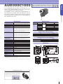
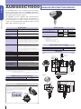
Advanced Ultraviolet Flame Detector
Products
AUD300C1000
Specifications
Model Selection
City gas, Natural gas, Propane gas, Kerosene, Heavy oil,
Applicable types of flames *1
Item
Coke oven gas, Hydrogen, Chlorine, Ammonia, Naphtha, Ethylene, etc.
Advanced
Model No.
AUD300C1000
Combined burner controller
RX-R40, RX-R44, RX-R46, AUR450C, AUR300C, AUR350C
Shutter voltage
ultraviolet
flame
AUD300C100D
AUD300C100T
Self-checking cycle
Approx. 24 Vdc (supplied from Burner Controller)
Approx. 75 cycles/ min.
Insulation resistance
Between flange unit mounting conduit and F-terminal (or blue lead wire),
AUD300C1100
between flange unit mounting conduit and G-terminal (or yellow lead wire),
between flange unit mounting conduit and S1-terminal (or white lead wire),
AUD300C110D
AUD300C110T
between flange unit mounting conduit and S2-terminal (or white lead wire):
50 MΩ min. by 500 Vdc megger at the above each location.
AUD300C110DT
detector
AUD300C100DT
(However, the tube unit must be removed.)
Between flange unit mounting conduit and F-terminal (or blue lead wire),
between flange unit mounting conduit and G-terminal (or yellow lead wire),
-20 to +120 °C
(while the shutter is
(However, when no flame is detected (shutter continuously open),
the maximum ambient operating temperature is 100 °C.)
-20 to +70 °C
90 %RH at 40 °C max. (without condensation)
4.9 m/s2 max., 10 to 55 Hz for 2 hours each in X, Y and Z directions
300 m/s2 in vertical and horizontal directions
350 kPa
Protection
Mounting posture
Mounting
Lead wires
Electric wire pipe mounting conduit
Flame signal wire requirements
and extension distance
Materials
Main body color
Weight
Expiration date of tube unit and
shutter unit
Standards compliance *2
Item
Packing nut
None
Maintenance Parts (sold separately)
AUD Maintenance Kit
(includes shutter and tube units)
Item
No inspection certificate
Inspection certificate included
Model No.
AUD60A1000
AUD60A100D
Dimensions
IP66 (except a conduit tube connection port)
-45 to +90° (in vertical direction)
(Unit: mm)
54.5
G1 (at the mounting section for sighting pipe)
AWG18 heat resistant silicone cables, with 2.4 m color lead wires
1/2-14NPSM
Requirements: 600 V vinyl insulation wires,
IV wires with 2.0 mm2, Max. 200 m
Main body: Heat resistant resin
Mounting section: Aluminum
Purple (equivalent to DIC257)
Approx. 630 g
3 years
Tropicalization
Model No.
81409780-001
81409482-001
Bushing 1× 3/ 4
20.5
Vibration resistance
Impact resistance
Pressure resistance for flange
None
Tropicalization
Inspection certificate provided None
Tropicalization
None
Inspection certificate provided Tropicalization
153.5
24.5
88
opening and closing)
Ambient storage temperature
Ambient humidity
Inspection certificate provided
None
Inspection certificate provided
Condenser None
Special treatment
None
(104.6)
88
During flame detection
Additional features
None
φ38.6
between flange unit mounting conduit and S1-terminal (or white lead wire),
between flange unit mounting conduit and S2-terminal (or white lead wire):
1500 Vac for 1 min or 1800 Vac for 1 sec at the above
each location. (However, the tube unit must be removed.)
Lens type
Standard
Optional Parts (sold separately)
(67.5)
Dielectric strength
Flame detectors
The AUD300C1000 Advanced Ultraviolet Flame Detector is designed to detect ultraviolet radiation from an oil or gas burner flame,
for use with both batch and continuous operation.
The AUD300C is used in combination with a dedicated burner controller. By means of the built-in shutter, any malfunction of the UV
flame detector or burner controller is detected by the continuous
self-checking (Dynamic Self-Check) function, ensuring highly reliable combustion safety control.
G1
13.3
20.7
CE, UL, CSA
*1 For applications using coke oven gas, hydrogen, chlorine, ammonia, naphtha, ethylene, etc., in
which the burner structure may impose restrictions on the mounting of the flame detector, it is
necessary to check that flame monitoring is reliable.
*2 Standards approvals are valid only for a combination of AUR450C, AUD300C, and Q241A104
Electric wire mounting conduit 1/2-14NPSM
MADE IN JAPAN
39.5
AUD300CX000
XXXX XXXXX
AUD Maintenance Kit
(54.5)
使用期限・GOOD THRU
For further details, please refer to specifications sheet No. CP-SS-1806E.
〈Model No.:AUD60A1000〉
The AUD maintenance kit includes the assembled tube unit
and shutter unit, as well as consumables such as the main
unit flange and O-ring for the cover, expiration label, etc.
1:Expiration date label
使用期限・GOOD THRU
27
Products
AUD500C11000
Advanced Ultraviolet Flame Detector
Specifications
Model Selection
hydrogen, chlorine, ammonia. naphtha, ethylene, etc.
Approx. 24 Vdc (supplied from Burner Controller)
Self-checking cycle
Approx. 75 cycles / min
Insulation resistance
Between flange mounting part and F-terminal (or blue lead wire),
between flange mounting part and G-terminal (or yellow lead wire),
between flange mounting part and S1-terminal (or white lead wire),
between flange mounting part and S2-terminal (or white lead wire):
Ambient temperature
Ambient storage temperature
Ambient storage humidity
Vibration resistance
Pressure resistance for mounting part
Protection
Mounting posture
90 % RH at 40 °C max. (without condensation)
AUD500C1111_ _
Optional parts (sold separately)
Note: This item is necessary.
Item
Model No.
81441151-001
Adapter (G2-1/ 4 R1)
Dimensions
•Body
(Unit: mm)
MADE IN JAPAN
1500 Vac for 1 min or 1800 Vac for 1 s at each of the above locations.
(However, the tube unit must be removed)
-20 to +60 °C
-20 to +70 °C
AUD500C1110_ _
AUD500C1101_ _
SERIAL NO:
between flange mounting part and S1-terminal (or white lead wire),
between flange mounting part and S2-terminal (or white lead wire):
Condenser
Replace the blank (_ _) in the mobel number with one of the for choices below.
0 : Standard product
D: Inspection certificate included
OT: Tropicalization
DT: Inspection certificate + tropicalization
Y: Traceability certificate included
E: Heavy duty coating + inspection certificate
50 MΩ min. by 500 Vdc megger at each of the above locations.
(However, the tube unit must be removed)
Between flange mounting part and F-terminal (or blue lead wire),
between flange mounting part and G-terminal (or yellow lead wire),
Dielectric strength
AUD500C1100_ _
10 m
3m
10 m
Model No
Standard
4.9 m/s2 max., 10 to 55 Hz for 2 hours each in X, Y and Z directions
690 kPa
IP67
Cover setscrew
(width across flat: 2)
G2-1/4
-45 to +90° (in vertical direction)
Flange: Parallel pipe thread G2-1/4, Adapter: Taper pipe thread R1
AWG18 heat-resistant silicone cables (4 cores),
3 or 10 m (depending on the model number)
Flame signal wire requirements IV wires with 2.0 mm2 and max. 200 m in length
and extension distance
Aluminum
Materials
Purple (equivalent to DIC257)
Color
Approx. 2.5 kg
Mass
Expiration date of tube unit and shutter unit 3 years
Mounting (on the monitoring pipe)
Accessory cable length
Name plate
35
03
185
124
φ1
φ103
Shutter voltage
Advanced ultraviolet flame detector
労(平 )検
for Explosion Protection and Safety Instrumentation (NEPSI).
City gas, natural gas, propane gas, kerosene, heavy oil, coke oven gas,
Lens type
cable length
3m
第 号
Applicable types of flame*1
Accessory
Item
DATE CODE:
Product qualified by Technology Institution of Industrial
Safety (TIIS) and National Supervision and Inspection Center
SHUTTER CURRENT
:180mA Max.
SHUTTER VOLTAGE
:DC24V
SENSOR CURRENT
:5.5mA Max.
SENSOR VOLTAGE
:420Vp-p
AMBIENT TEMPERATURE
:60℃max
注意:70℃以上の耐熱ケーブルをご使用下さい。
CAUTION:Use heat resistant conductors of 70 min
Explosion-protection certified
形番 MODEL:AUD500C21
Ex d IIC T4
24.5
Explosion-proof housing
火炎検出器 FLAME DETECTOR
防爆構造 FLAME PROOF:Ex dIIC T4
Flame detectors
The AUD500C Explosion-Proof Advanced Ultraviolet Flame
Detector (hereafter referred to as the AUD500C) is designed to
detect ultraviolet radiation from an oil or gas burner flame, for use
with both batch and continuous operation.
The AUD500C is used in combination with a dedicated burner
controller. By means of the built-in shutter, any malfunction of
the UV flame detector or burner controller is detected by the
continuous self-checking (Dynamic Self-Check) function, ensuring
highly reliable combustion safety control.
*1. For applications using coke oven gas, hydrogen, chlorine, ammonia. naphtha, ethylene, etc., in
which the burner structure may impose restrictions on the mounting of the flame detector, it is
necessary to check that flame monitoring is reliable.
52.8
119.2
189
For further details, please refer to specifications sheet No. CP-SS-1873E.
Outside earth screw M4
G 1/2
Item
AUD Maintenance Kit (includes shutter and tube units)
•Bushing
32
Maintenance parts (sold separately)
35
Model No.
AUD60A1010
(210)
22
Adapter
〈Model No.:AUD60A1010〉
9
R1
74
AUD Maintenance Kit
0
φ8
Plug with hexagon socket (width across flat: 5)
2 points
AUD500
2−Rc 1/ 8 (for air purge)
Packing
The AUD60A1010 maintenance kit includes the assembled
shutter unit and tube unit, as well as consumables such as
the AUD500C main unit flange and tight-fitting cover O-ring,
expiration label, etc.
1:Expiration
date label
使用期限・GOOD THRU
Example of
an attached label
使用期限・GOOD THRU
28
17
54
75.5
Advanced Ultraviolet Flame Detector Socket for the AUD15 Tube Unit
Products
AUD100/110
AUD100
Flame detectors
The AUD100/110 is a dedicated socket for the AUD15 tube
unit, and is designed for monitoring batch operation oil or gas
burner combustion.
Two models, the AUD100 lead-wire model
and the AUD110 terminal block model,
are available to meet wiring
or installation requirements.
AUD15
(tube unit)
AUD110
Specifications
Description
Item
Applicable type of fuel *1 City gas, natural gas, propane gas, kerosene, heavy oil, coke oven gas, hydrogen, chlorine, ammonia. naphtha, ethylene, etc.
AUD110C
Mass
AUD100C
Approx. 120 g
Approx. 120 g
(with the AUD15: approx. 140 g)
(with the AUD15: approx. 140 g)
Socket: Aluminum
Materials
Aluminum
Insulation resistance
50 MΩ min by 500 Vdc megger
(between each lead wire and the metal part of socket when the AUD15 is removed)
Terminal block: Heat-resistant resin (PBT + GF30) (black)
Dielectric strength
50 MΩ min by 500 Vdc megger
(between each of terminals F and G and the metal part of socket when the AUD15 is removed)
1500 Vac for 1 min or 1800 Vac for 1 s
(between each of terminals F and G and the metal part of socket when the AUD15 is removed)
1500 Vac for 1 min or 1800 Vac for 1 s
(between each lead wire and the metal part of socket when the AUD15 is removed)
Ambient temperature -20 to +120 °C
Ambient storage
-20 to +70 °C
temperature
Ambient humidity
Allowable pressure
Vibration resistance
Protection
Mounting nut
Lead wires
90 % RH at 40 °C (without condensation)
35 kPa
5 m/s2 max. (10 to 60 Hz for 2 hours each in X, Y and Z directions)
IP65 (JIS C 0920/IEC 60529) with pipes and wires connected
Conduit
G1 (R1 and 1-11BSP are connectable)
AWG #18 (approx. 1.2 mm2) flame retardant cross-linked polyethylene insulated cable, approx. 1800 mm long (blue and white) (only AUD100)
G1/2 (1/2-14BSPP is connectable)
Flame signal wire
Standard: 2.0 mm2, 600 Vac cable with PVC insulation ("IV cable"). Max. length: approx. 200 m
*1. For applications using coke oven gas, hydrogen, chlorine, ammonia. naphtha, ethylene, etc., in which the burner structure may impose
restrictions on the mounting of the flame detector, it is necessary to check that flame monitoring is reliable.
For further details, please refer to specifications sheet No. CP-SS-1877E.
Model No.
AUD100C100_
AUD100C1000-A15
Terminal block model without the AUD15
Terminal block model with the AUD15
AUD110C100_
AUD110C1000-A15
Replace the blank ( _ ) in the mobel number with one of the for choices below.
0 : Standard
D : Inspection certificate
T*: Tropicalization treatment
B*: Inspection certificate + tropicalization treatment
* Only AUD110 Series
•
(140)
90
G1
Lens unit (focal length: 30 mm)
Lens unit (focal length: 30 mm) with inspection certificate
*1. AUD15C1000
Thermolabel
G1/2
(76)
M3.5 terminal screw
•AUD100C100_ with the AUD15
(105)
Approx. 1800
55
Lead wire
AUD15
Dia. 24
Model No.
AUD15C1000
81403159
FSP136A100
FSP300C100
FSP100L70000
FSP100L7000D
FSP100L30000
FSP100L3000D
G
AUD15
Dia. 40
Item
Tube unit (ultraviolet photoelectric tube) *1
Seal adapter *2
Analog flame meter
Flame simulator
Lens unit (focal length: 70 mm)
Lens unit (focal length: 70 mm) with inspection certificate
60
F
(64)
Optional parts (sold separately)
(Unit: mm)
52
Item
Lead-wire model without the AUD15
Lead-wire model with the AUD15
Dimensions
AUD110C100_ with the AUD15
dia. 40
Model Selection
G1
(64)
G1/2
(41)
Time period label
•Seal adapter (model No.: 81403159)
Light-receiving
glass surface
Seal adapter
117
Product label
77
Dia. 42
20
AUD110
18
*2. Seal adapter (model No. 81403159)
Refer to the following dimensions
39
Air purging connection port
APT 1/8
Hexagon socket tapered plug
G1
29
Products
AFD100A/B
Visible Light Frame Detector
The AFD100A/B visible light flame detector is a batch operation
flame sensor that detects visible light from an oil combustion
burner flame.
There are two different types for different burner constructions,
depending on whether the light is received from the front or
side.
Flame detectors
Be sure to combine this product with the burner controller appropriate
for the AFD100.
C554A compatible replacement adapter
Specifications
Model
AFD100A0700
AFD100B0700
Illuminance-current characteristics
(Conditions: VR = 5 V, at 25 °C)
Dark characteristics
Direction light received
Type
Front
Top view
Compatible Burner controller
R4424 or R4440H series product that supports AFD
Side
Side view
At an illuminance of 10 lx (color temperature of 2,856 K), 30 μA or more.
(Measurement conditions: supply voltage: 5 V, load resistance: 20 kΩ, room temperature/normal humidity)
In total darkness (0 lx), 24 μA or lower.
(Measurement conditions: supply voltage: 5 V, load resistance: 20 kΩ, room temperature/normal humidity)
Dielectric strength
Commercial frequency 500 Vac, applied for 1 minute with no abnormalities
(Between lead wires and flange, at room temperature and normal humidity)
Insulation resistance
With a 500 Vdc megger, 50 MΩ or more.
(Between lead wires and flange, at room temperature and normal humidity)
Allowable ambient temperature
Storage temperature
-20 to +60 °C
-20 to +70 °C
Allowable ambient humidity
Vibration resistance
40 °C, 90 % RH or less (without condensation)
Cable
Double amplitude 4.9 m/s2, 10-55 Hz, 2 hours each in X, Y, Z directions
Heat-resistant flat plastic cable, 0.75 mm2
Material
Black (terminal F), white (terminal G)
Main unit/flange: nylon 6 (blue)
Flange
Approx. 25 g
Mounting
Mass
Dimensions
Model Selection
Item
Visible light flame detector
Type
Top view
Side view
(Unit: mm)
Model No.
AFD100A0700
AFD100B0700
Heat resistant flat plastic cable (black/white)
0.75mm2
Length 700 mm ±25 mm
Optional Parts (sold separately)
Item
C554A1299-1 compatible replacement adapter
C554A06S1-1 compatible replacement adapter
Model No.
81447108-001
81447108-002
(16)
4.5
7.4±0.2
22
φ9.5max.
(32.7)
AFD100A0700 (top view type)
Sensing surface
AFD100B0700 (side view type)
14.3
Sensing surface
30
44
34
6.5
φ14.2
54.7
Visible Light Flame Detecter
Products
AFD110A
The AFD110A visible light flame detector is a batch operation
flame sensor that detects visible light from an oil combustion
burner flame.
This product must be combined with an AFD-compatible Burner
controller.
Flame detectors
Specifications
Illuminance-current characteristics
(Conditions: VR = 5 V, at 25 °C)
Dark characteristics
At an illuminance of 10 lx (color temperature of 2,856 K), 30 μA or more.
(Measurement conditions: Supply voltage: 5 V, load resistance: 20 kΩ, room temperature/normal humidity)
In total darkness (0 lx), 24 μA or lower.
(Measurement conditions: Supply voltage: 5 V, load resistance: 20 kΩ, room temperature/normal humidity)
Commercial frequency 500 Vac, applied for 1 minute with no abnormalities.
Dielectric strength
(Between lead wires and flange, at room temperature and normal humidity)
Insulation resistance
With a 500 Vdc megger, 50 MΩ or more.
Allowable ambient temperature
(Between lead wires and flange, at room temperature and normal humidity)
-20 to +60 °C
Storage temperature
Allowable ambient humidity
-20 to +70 °C
Vibration resistance
Cable
Double amplitude 4.9 m/s2, 10-55 Hz, 2 hours each in X, Y, Z directions
40 °C, 90 % RH or less (without condensation)
Heat-resistant flat plastic cable, 0.75 mm2 Black (terminal F), white (terminal G)
IP44 (with conduit and wiring connected)
Protection
Material
Mounting
Compatible burner controllers
Mass
Aluminum
G3/4 inch flange
R4424 or R4440H series product that supports AFD
Approx. 200 g
Optional Parts (sold separately)
Model selection
Item
Model No.
AFD110A0000
Visible light flame detector
Item
Model No.
Replacement sensor
AFD100A0035
Dimensions
(Unit: mm)
White
G
117
φ14.2
φ6
2
(15)
F
(12)
φ9.3max
Black
17
10
32.7
22
(82)
20
G3/4
Replacement sensor (AFD100A0035)
G3/8
φ40
M4 connection screw
G
F
Terminal block
31
Products
C6097A
Gas Pressure Switch
Pressure Switch
The C6097A gas pressure switch is a pressure detector for city
gas, natural gas, LP gas and air.
The external electrical circuit is turned on or off according to
the preset value.
This device can be used in a variety of ways including detection
of maximum/minimum gas/air pressure supplied to the gas
burning device, burner blower interlock, or filter clogging.
As a supplementary part (sold separately), there is a switchaction display light for switching the gas pressure.
Specifications
Natural gas, liquefied petroleum gas, and air
Applicable fluids
Model
Control action
C6097A0110
ON/OFF
C6097A0210
ON/OFF
C6097A0310
ON/OFF
C6097A0410
ON/OFF
C6097A0510
ON/OFF
Setting range
0.1 to 1 kPa
40 Pa (fixed)
0.25 to 5 kPa
60 Pa (fixed)
3 to 15 kPa
280 Pa (fixed)
10 to 50 kPa
700 Pa (fixed)
10 to 70 kPa
800 Pa (fixed)
On-off differential
(nominal value)
Maximum Allowable pressure
Setting accuracy
20 kPa
30 kPa
50 kPa
150 kPa
150 kPa
0.1 ±0.06 kPa, 1 ±0.15 kPa
0.25 ±0.15 kPa, 5 ±0.75 kPa
3 ±0.9 kPa, 15 ±2.25 kPa
10 ±2.4 kPa, 50 ±7.5 kPa
10 ±3 kPa, 70 ±8 kPa
Low pressure side: when at atmospheric pressure. High pressure side: when pressure is increasing.
SPDT contact output
Output
On pressure down, terminals 1-3 closed, terminals 2-3 open.
On pressure rise, terminals 1-3 open, terminals 2-3 closed.
Contact raiting
Resistive load: 250 Vac, 5 A
Inductive load: 250 Vac, 3 A (power factor: 0.6)
Minimum contact operating current and voltage: 50 mA, 24 Vdc
Insulation resistance
Dielectric strength
100 MΩ min. between each terminal and non-live metal part with a 500 Vdc megger
Betw. terminals with the same polarity: 1000 Vac, 50/60 Hz for 1 min
Betw. each terminal and non-electrically charged metal parts: 1500 Vac, 50/60 Hz for 1 min
Leakage current of 1 mA or less under these conditions
Contact resistance
Fluid temperature
Ambient temperature
Initial 100 mΩ max. (measured by voltage drop method at 6–8 Vdc and 1 A)
-15 to +60 °C (without freezing or condensation)
-15 to +60 °C (without freezing or condensation)
Durability
Wiring terminal
Installation direction
Over 100,000 operations at the rated contact voltage and current
M3.5 screw terminal
Protection
Vertical, or horizontal with the pressure setting dial facing upwards.
IP54
Mass
High-pressure gas contacting material
Accessories (sold separately)
260 g
Die-cast aluminum (housing), NBR/nitrile rubber (diaphragm)
Switch operation indicator lamp (100/200 Vac)
Model No.: 81404156
Model Selection
Dimensions
Item
Switch operation indicator lamp (100/200 Vac)
38.4
86
Housing
Die-cast aluminum
Model No.
81404156
φ9
(NO)
For a pressure rise:
Terminals 3–1 open
Terminals 3–2 closed
Voltage
For a pressure drop:
Terminals 3–1 closed
Terminals 3–2 open
1
(NC)
3
(COM)
Low-pressure port
Rp 1/8
32∞
Loads
45
21
61
2
Rp 1/4 high-pressure port
with plug ( use 6 mm hex wrench )
30∞
R 20
69
69
Monitoring pressure gauge port
M4 plug screw, length 6
Wiring
PBT
Wiring port φ22
59
Optional Parts (sold separately)
68.4
68.4
10.5
Gas pressure switch
26.5
Model No.
C6097A0110
C6097A0210
C6097A0310
C6097A0410
C6097A0510
13
10.5
Item
R 32
Note
3 unthreaded holes for bracket
installation (depth 8)
Rp 1/4 high-pressure port
Note: Remove the dust seal before using
Note. Use M4 self-tapping screw or provide the hole with M4 threads before use.
32
(Unit: mm)
High Power Igniter
Products
S7200A
Igniter
The S7200A igniter is a solid-state, high performance ignition
transformer used with business and industrial oil-fired gun-type
burners and gas-fired power burners.
Compared with our other products, this unit has twice the
ignition energy, equivalent to the amount of a coil ignition
transformer, therefore making it possible to use this transformer
with burners that previously could be ignited only by using a
coil ignition transformer.
Compared to the S720, the high-voltage cable can be extended
to 2 meters, and at that length the power does not drop.
Specifications
Gas-fired power burner
Oil-fired gun-type burner
Applicable burner
Model
Rated power and voltage
S7200A100−OHR
S7200A200−OHR
S7200A100−GHR
S7200A200−GHR
100 Vac 50−60 Hz
200 Vac 50−60 Hz
100 Vac 50−60 Hz
200 Vac 50−60 Hz
2
10 + 15 m/s
No. of electrodes
1
10 + 15 m/s
60 min, 50 % *1
6 min, 20 %
Note: The percentage figure is the allowable usage rate for continuous ignition. For example, “6 min, 20 %” means that 1.2 min is the max. continuous discharge time (4.8 min rest).
Recommended air speed
Time rating
Half-wave
Bullet terminal
Characteristics
High-voltage side connection
Grounding method
Power consumption
Neutral ground
70 VA
One ground wire
75 VA
55 VA
65 VA
Approx. 650 g
Mass
Operating voltage
-15 % to +10 % of rated supply voltage
High voltage side output voltage Approx. 20 kVo-p *2
Approx. 16 kVo-p *2
Recommended electrode spacing 3.5 ±0.5 mm
2.5 ±0.5 mm
Electrical life
100,000 operations or 10 years under standard conditions (rated supply voltage, air speed between electrodes, room temperature, normal humidity)
Induced lightning surge resistance 10 kV or more between wires and between wires and ground (1.2/50 µs, 100 Ω or more)
Insulation resistance
Between ground terminal and input terminals using a 500 Vdc megger, 50 MΩ or more (excluding high voltage terminals)
Dielectric strength
Between ground terminal and input terminals, 1800 Vac, 1 s without abnormalities (excluding high voltage terminals)
Operating ambient temperature
Operating ambient humidity
Storage ambient temperature
Ground terminal
-20 to +60 °C
90 % RH or less at 40 °C (no leak discharge due to condensation between the secondary terminals and the secondary terminal and ground)
-20 to +60 °C
If there is poor electrical contact between the ground terminal and the burner main unit, high frequency noise will occur and create electrical interference in other
equipment, radios, TVs, etc. Be sure to remove the paint from the point of contact on the burner so that there is a good connection.
Recommended high voltage cable Standards
High-voltage AIRN (JIS3405) cable for use in vehicles or neon light wiring, 300 mm (standard) to 2000 mm (maximum) in length.
/Dimensions
(However, if the wire is longer than 600 mm, use an insulator to raise it by at least 50 mm. Separate the cables by at least 3 cm.)
Power cord
Case material
Pullout strength
More than 290 kPa. AIRN cable (JIS3405) must be used to prevent the cable from pulling out during transport or under use conditions.
500 ±30 mm (plastic cabtyre cable, 2 cores / VCTFK, JIS3306 / 0.75 mm2, 30/0.18 diameter 4.4 × 6.8 black)
Polycarbonate
Case color
Mounting
Black
Mounted on metal plate (1 mm thick or more)
Mounting position
Mounted such that ground terminal makes contact with metal plate.
*1. This is the value when used in an ambient temperature of less than 40 °C and is 60 min. and 33 % when used in an ambient temperature between 40 °C and 60 °C.
*2. For the rated voltage, room temperature, normal humidity and 20 pF voltage divider input capacity.
Model selection
Item
Dimensions
Model No.
S7200A100-OHR
S7200A200-OHR
S7200A100-GHR
S7200A200-GHR
Gun type oil burner
51
*
Ground terminal
5.2 hole
4
19
Power gas burner
(Unit: mm)
High voltage terminal
Dia. 6.4 bullet terminal
(free-machined brass rod) (2)
59
29
72
73
83
Model No.
YS7200A300-S2
YS7200A500-S2
YS7200A1000-S2
YS7200A2000-S2
94.5
Cable length
30 cm
50 cm
1m
2m
73
Optional Parts (sold separately)
Item
High voltage cable (10 units)
500±30
5
5.2
0.8
60±10
Power cord
Plastic cabtyre cable, 2 cores
VCTFK JIS C 3306
0.75 mm2, 30/0.18, dia. 4.4 × 6.8, black
*Models with number S7200A-G for gas-fired power burners have only one terminal output
and therefore there is no bullet terminal on this side.
33
Products
FSP136A
Analog Flame Meter
Specifications
•Analog flame meter
Dimensions
(Unit: mm)
Compatible models
AUR300C/350C, AUR450C, RA890F/G, R4750, R4780,
Operating principle
FRS100B/C, FRL100/101,.etc
Moving coil
Operating/storage
0 to 40 °C
Strap
• Body
Operating direction
Vertical (unit has a strap on top)
Indication accuracy
Recorder output accuracy
±2.5 % FS
Color
Black
Mass
Approx. 450 g
レコーダ
OFF
105
25
Recorder output
R485B*, RA890F/G,
No display
Display in the
Output in the
R4750C, R4780B/C,
0-15 μAdc range.
0-150 mVdc range.
(special)
FRL100/101,
FRS100B/C,
Banana plugs
545
Crimp
terminals
Recorder plug
Display in the
Output in the
0-15 μAdc range.
If the flame current
fluctuates greatly,
0-150 mVdc range.
If the flame current
fluctuates greatly,
a smoothed value is
a smoothed value is
displayed.
Display
in the 0-7.5 Vdc range.
output.
-
*: discontinued model
Model Selection
34
Probe
• Lead wire for recorder
AUR300C/350C,
AUR400C/450C,
Item
7.5V
60
• Tester cable
Analog meter display
R7257A*, R7258A*,
R7259B*
R7247B/C, R7476A
SPL
100
and analog meter indication differs according to the measurement range.
The table below shows the differences.
Model to be
measured
15UA
7.5V
•Range selection switch
Measurement range differs according to the model to be measured,
Analog flame meter
7.5V
0
μA
0
15
80% RH max. at 40 °C
(no condensation allowed)
7.5V
μA · V
TAUT BAND
Operating/storage
humidity range
SPL
5
2.5
temperature range
Range selection
switch position
OFF
15UA
10
5
Model No.
FSP136A100
180
Peripheral devices
The FSP136A analog flame meter is an optimal support tool for
maintenance and troubleshooting.
The analog flame meter is used for measuring the flame
voltage or flame current of combustion safety equipment.
In addition, the flame current level can be easily recorded by
connecting to the recorder jack.
1560
Flame Simulator
Products
FSP300C100
Peripheral devices
The flame simulator has the same characteristics as a
combustion flame. If problems occur with the combustion
safety controller, for example, or when the burner sequence is
being checked, the flame simulator can be connected to the
flame detection circuit in order to check easily for errors in the
flame detector, burner controller, amplifier, external circuits,
etc., without actually using a burner.
Specifications
Compatible equipment
Simulator
FSP300C100
Combustion safety controller
Amplifier
Burner controller
RX-R40C
Built-in
Flame detector
Flame rod
Ultraviolet flame detector
-
(black)
Method of checking action of flame relay 2K
Figure
(Caution: Simulator must not touch any point other than those indicated.)
AUD300C
Attach the FSP300C100 to the relay terminals and connect lead wires to terminals
AUD500C
F, G, S and S.
Fig. 1
Connect lead wires F and G to RX-R40 terminals B6 (F) and A7 (G), and then
connect the S and S lead wires to terminals B9 and A9.
Change the FLAME MODE switch on the FSP300C to SYNC.
-
RX-R20C
Built-in
AUD110C/100C
C7035A
-
AUR350C
Built-in
AUR300C
FRS100C
RA890G
AUD300C
-
Built-in
Built-in
C7027A
AUD500C
AUD110C/100C
-
C7035A
C7027A
-
AUD110C/100C
C7035A
C7027A
-
R4150P
(discontinued as
R7259B
(plug-in type)
of Sept. 2003)
R4750C
AUD110C/100C
C7035A
-
Built-in
C7027A
AUD110C/100C
-
C7035A
C7027A
R4780C
Built-in
AUD110C/100C
C7035A
C7027A
WN200A
(discontinued as of
Dec. 2000)
WN210A
(discontinued as of
Dec. 2000)
R7259B
(plug-in type)
AUD110C/100C
C7035A
C7027A
Attach the FSP300C100 to the relay terminals and connect the lead wires to
terminals F and G.
Connect lead wires F and G to RX-R20 terminals B6 (F) and A7 (G).
Change the FLAME MODE switch on the FSP300C to ON.
Attach the FSP300C100 to the AUR350C/300C terminal block (S, S, G, F).
Change the FLAME MODE switch on the FSP300C to SYNC.
Fig. 2
Fig. 3
Attach the FSP300C100 to the relay terminals and connect the lead wires to
terminals F and G.
Connect lead wires F and G to FRS100C terminals 5 (F) and 6 (G).
Change the FLAME MODE switch on the FSP300C to ON.
Fig. 4
Attach the FSP300C100 to the relay terminals and connect the lead wires to
terminals F and G.
Connect lead wires F and G to RA890G terminals F and G.
Fig. 5
Change the FLAME MODE switch on the FSP300C to ON.
Attach the FSP300C100 to the relay terminals and connect the lead wires to
terminals F and G.
Connect lead wires F and G to R4150P terminals F and G.
Change the FLAME MODE switch on the FSP300C to ON.
Attach the FSP300C100 to the relay terminals and connect the lead wires to
terminals F and G.
Connect lead wires F and G to R4750P terminals F and G.
Change the FLAME MODE switch on the FSP300C to ON.
Attach the FSP300C100 to the relay terminals and connect the lead wires to
terminals F and G.
Connect lead wires F and G to R4780C terminals 23 (F) and 24 (G).
Change the FLAME MODE switch on the FSP300C to ON.
Attach the FSP300C100 to the relay terminals and connect the lead wires to
terminals F and G.
Connect lead wires F and G to WN200A/210A terminals F1 and G.
Fig. 6
Fig. 7
Fig. 8
Fig. 9
Change the FLAME MODE switch on the FSP300C to ON.
Model Selection
Item
Flame simulator
Model No.
FSP300C100
35
Products
FSP300C100
Flame Simulator
Dimensions
(Unit: mm)
42
44
29
30
FSP300C100
S2
LED2
FLAME
MODE
48
Peripheral devices
LED1
SHUTTER
LINE CHECK
S1
4.5 11
7.5
33
SHUTTER
G
SYNC UV
OFF SENSOR
F
ON
SW1
Figure1
FSP300C100-RX-R40C
RX-L80
Figure2
FSP300C100-RX-R20C
RX-R40C
RX-L80
Figure3 FSP300C100-AUR300/350
Figure4
FSP300C100-FRS100C
RX-R20C
FRS100 FLAME RELAY
AUR350
POWER
0
POWER
ADR
C
4
8
FLAME
SHUTTER
START CHECK
LDR
FLAME
RS485
Relay terminal
SHUTTER
14
14
13
13
SHUTTER
(G)
Relay terminal
SHUTTER
S
FSP300C100
S2
LED1
SHUTTER
LINE CHECK
S1
LED2
FLAME
MODE
S
G
G
SYNC UV
OFF SENSOR
F
ON
F
SHUTTER
SW1
G
G
SYNC UV
OFF SENSOR
F
ON
FSP300C RX-R20
GA7
F B6
− 10
0-5V
+
9
K3
K1
F
K2
SW1
*Attach the FSP300C100 to the relay terminals.
Figure5
FSP300C100
S2
LED1
SHUTTER
LINE CHECK
S1
LED2
FLAME
MODE
FSP300C100-RA890G
*Attach the FSP300C100 to the relay terminals.
Figure6
12
UV SENSOR
(F) 11
Relay terminal
FSP300C RX-R40
S B9
S A9
GA7
F B6
FSP300C100-R4150P
12
11
LED2
FLAME
MODE
10
9
8
8
7
7
6
6
5
5
4
4
FSP300C100
S2
LED1
SHUTTER
LINE CHECK
S1
Figure7
(G)
6
5
(F)
*Attach the FSP300C100 to the relay terminals.
3
FSP300C100-R4750C
F
SW1
*Attach the FSP300C to terminals 11 through 14.
3
G
G
SYNC UV
OFF SENSOR
F
ON
Figure8
FSP300C100-R4780C
2K
Relay terminal
SHUTTER
FSP300C100
S2
LED2
FLAME
MODE
G
G
SYNC UV
OFF SENSOR
F
ON
SW1
Relay terminal
Relay terminal
F
LED1
SHUTTER
LINE CHECK
S1
SHUTTER
FSP300C100
S2
SHUTTER
G
増幅器
F
G
Relay terminal
SHUTTER
LED2
FLAME
MODE
F
SW1
G
SYNC UV
OFF SENSOR
F
ON
FSP300C100
S2
LED1
SHUTTER
LINE CHECK
S1
LED1
SHUTTER
LINE CHECK
S1
G
G
LED2
FLAME
MODE
F
F
SW1
G
SYNC UV
OFF SENSOR
F
ON
G
F
(G)
24
23
(F)
FSP300C100
S2
LED1
SHUTTER
LINE CHECK
S1
LED2
FLAME
MODE
*Attach the FSP300C100 to the relay terminals.
Figure9
FSP300C100-WM200A/WN210A
Flme detectory relay
F1
F2
F3
G
F4
Relay terminal
SHUTTER
FSP300C100
S2
LED1
SHUTTER
LINE CHECK
S1
LED2
FLAME
MODE
*Attach the FSP300C100
to the relay terminals.
36
SW1
G
SYNC UV
OFF SENSOR
F
ON
G
F
SW1
G
SYNC UV
OFF SENSOR
F
ON
G
F
*Attach the FSP300C100
to the relay terminals.
*Attach the FSP300C100 to the relay terminals.
*Attach the FSP300C100 to the relay terminals.
Flame
Safeguard
System
Application Examples
(RX Series)
Selecting an RX Series
Combustion Safety Controller
Boiler
Deodorizing Furnace
Small Holding Furnace
Small Melting and Holding Furnace
Large Melting Furnace
Heating Furnace 1 to 4
Heating Furnace
(Regenerative Burner)
Settings Tables
37
Application Examples
Selecting an RX Series Combustion Safety Controller
Various configurations and specifications exist for combustion equipment depending on the amount of combustion, ignition method, combustion
control method, and specific equipment specifications.
The versatile RX Series can be used for a variety of combustion equipment, from small batch furnaces to large-scale steel plant combustion
furnaces, and its functions can be easily switched using a PC loader.
To select the appropriate RX Series device, please refer to the pipe trains, sequence charts, or other relevant material in this document.
Selecting an RX Series Combustion Safety Controller
•Single burner
This is a system that controls a single burner using a series of devices such as a blower, combustion gas pressure switch, combustion
air pressure switch, and safety shutoff valve.
APL : Low air pressure switch
GPL : Low gas pressure switch
GPH : High gas pressure switch
FD : Flame detector
IG : Ignition transformer
PV : Pilot safety shutoff valve
MV : Main safety shutoff valve
CM : Control motor
PV
Blower
APL
IG
FD
CM
Fuel
GPL
GPL
GPH
MV
•Multiple burners
This is a facility with many burners in a single combustion furnace. The following diagram shows a multiburner furnace where equipment
such as blowers, pressure switches, safety shutoff valves, etc. are shared.
Note: A single facility with multiple combustion furnaces is called a multi-zone facility.
APL : Low air pressure switch
GPL : Low gas
pressure switch
GPH : High gas
blower
pressure switch
FD : Flame detector
IG : Ignition transformer
PV : Pilot safety shutoff valve
MV : Main safety shutoff valve
CM : Control motor
38
PV
APL
IG1
IG2
FD1
CM
Fuel
GPL
GPL
GPH
MV
FD2
Application Examples
•Method of controlling combustion amount
ON/OFF control
The amount of combustion is controlled by igniting and extinguishing the burner. This method is frequently adopted by small
combustion furnaces, and the combustion furnace equipment configuration can be made quite simple.
Also, the time-proportional ON/OFF control method uses repeated short intervals of combustion in order to reach the desired amount of
Selecting an RX Series Combustion Safety Controller
heat. In this case, it is necessary to periodically inspect and replace equipment in consideration of the service life of the safety shutoff
valve and control device.
(Models RX-R22/46 allow driving of the load and ensuring of safety by using the RX-R external relay. These models make highly frequent
ON/OFF control possible without relying on the service life of the RX Series internal relay.)
Hi-Lo-Off Control
The amount of combustion is controlled in small increments by ON/OFF control. This is used in small to medium sized combustion
furnaces.
Proportional control
Proportional control is able to continuously control the amount of combustion and is widely adopted in combustion furnaces that require
exact control of the combustion process. This is generally used in large combustion furnaces to continuously maintain a desired amount
of combustion between minimum and maximum. However, this method requires a variety of equipment, such as control motors,
equalizing valves, etc., which makes its configuration and adjustment complicated in comparison to ON/OFF control.
•Synchronous and asynchronous ignition
Synchronous ignition is when multiple burners are ignited in sync (simultaneously) in a multi-burner setup. Because multiple burners
share safety shutoff valves, the configuration can be made simpler by reduction of the number of safety shutoff valves. However, if there
is a flame failure in one burner, then multiple burners must be shut off because the safety shutoff valve is shared.
Asynchronous ignition is when multiple burners are ignited asynchronously (at different times) in a multi-burner system. Because safety
shutoff valves are not shared, if there is a flame failure in one burner, the burner’s gas supply can be shut off without affecting other
burners. Also, since burners are individually ignited and extinguished, thinned-out operation and the stopping of burners when a
malfunction occurs is possible.
•Application Examples
Single burner
No.
1
2
3
Ignition method
Pilot
Interrupted pilot
Control method
Main combustion
facility
Reference page
Setup
Proportional control
Boiler
pages 40 and 41
page 60
Interrupted pilot
Proportional control Deodorizing furnace pages 42 and 43
page 60
Continuous pilot
ON/OFF
Small holding furnace pages 44 and 45
pages 62 and 63
Multiple burners
No.
1
2
3
4
5
6
7
Ignition method
Main combustion
Control method
facility
Burner
Pilot
Hi-Lo-OFF
Small melting
Asynchronous Interrupted pilot
holding furnace
ignition
ON/OFF
Large melting
Asynchronous
Direct ignition
(time proportional)
furnace
ignition
Asynchronous Interrupted pilot Proportional control Heating furnace 1
ignition
Asynchronous Continuous pilot Proportional control Heating furnace 2
ignition
ON/OFF
Heating furnace 3
Asynchronous Continuous pilot
(time proportional)
ignition
ON/OFF
Heating furnace 4
Asynchronous
Direct ignition
(time proportional)
ignition
ON/OFF
Heating furnace
Asynchronous Continuous pilot
(time proportional) (regenerative burner)
ignition
Reference page
Setup
pages 46 and 47
pages 62 and 63
pages 48 and 49
pages 64 and 65
pages 50 and 51
pages 64 and 65
pages 52 and 53
pages 66 and 67
pages 54 and 55
pages 66 and 67
pages 56 and 57
pages 68 and 69
pages 58 and 59
pages 68 and 69
39
Application Examples
Boiler
Pipe train
Single burner: Interrupted pilot ignition - Proportional control
When the RX-L start signal turns on and the steam pressure switch for the boiler call-for-heat signal turns ON, the prepurge begins.
The prepurge is a proven prepurge which sets the combustible air content to the maximum combustion position and then, when that
ends, moves to the minimum combustion position before finishing.
Boiler
Burner ignition is a low fire ignition, and after the main burner has ignited, control of the amount of combustion is started by a signal
from the pressure controller.
Between when the burner starts and the pilot burner ignites, whether the main safety shutoff valve is closed is an interlock condition.
When the boiler load decreases and the boiler pressure rises, the hot air pressure switch for the call-for-heat signal turns OFF, burner
combustion stops, and the postpurge begins. When the postpurge ends, the burner stops and enters standby mode.
Caution: The following diagram does not show the hot air
Seismoscope
pressure switch for the call-for-heat signal or the
controller for the amount of combustion.
SPH
Steam
LWLL
Boiler
Water
Chimney
APL
Seismoscope: Seismic sensor
APL: Low air pressure switch
GPL: Low gas pressure switch
GPH: High gas pressure switch
LWLL: Low water level shutoff
SPH: High steam pressure switch
FD: Flame detector
IG: Ignition transformer
PV: Pilot safety shutoff valve
MV: Main safety shutoff valve
CM: Control motor
Chimney
damper open LS
Blower
GPL
GPH
IG
Fuel
MV
CM
PV
RX configuration
RX-L80
RX-R20
/90
/40
Wiring
AC power source
H G
RX-L80/90
Start + call for heat
Reset
Seismoscope
Chimney damper open
CM open
CM closed
Gas pressure high
Gas pressure low
Air pressure low
Low water level shutoff
Steam pressure alarm
Other alarm
Proportional control
A-B0
A-B1
A-B2
A-B3
A-B4
A-B5
A-B6
A-B7
A-B8
A-B9
A-BA
A-A0
A-A1
A-A2
A-A3
B-A0
B-B0
B-A3
B-B3
B-A7
B-B7
B-A9
B-B9
B-AA
B-BA
39
1
AC power source
MV closed
Blower
CM open
CM closed
CM control output
Lamp
Lamp
B-B9
B-BA
B-A0
B-AA
A-A9
26
38
DC power source
24 V
TB1
TB2
Please refer to page 60 for the settings table.
40
H G
RX-R20/40
B-B0
B-B1
B-B2
B-B3
B-B4
B-B5
B-B6
B-B7
B-B8
TB1
TB2
A-A0
A-B0
A-B1
A-B2
A-A4
A-B4
A-B6
A-A7
A-A9
A-B9
IG
PV
MV
*1
FD
*1. For RX-R40
*2. For RX-R20
A-B6
A-A7
A-A9
A-B9
FD
Application Examples
Sequence chart
Power ON
Burner
ignition
Steady
combustion Postpurge
Boiler
Prepurge
Burner extinction
Start + call-for-heat signal
Seismoscope
Chimney damper open
CM open
CM closed
Gas pressure high (GPH)
Gas pressure low (GPL)
Air pressure low (APL)
Low water level shutoff
Steam pressure alarm
Other alarm
Proportional control
Blower
Control motor
CM open output
CM closed output
CM control output
MV closed
Ignition transformer (IG)
Pilot valve (PV)
Main shutoff valve (MV)
Flame detector (FD)
41
Application Examples
Deodorizing Furnace
Piping train
Single burner: Interrupted pilot ignition - Proportional control
The burner is in sync with operation of the furnace, but the input route of the processed gas switches over at a certain period of time
and waste heat is recovered.
The changeover valve for processed gas and exhaust is operated by an external control circuit.
Deodorizing Furnace
The main gas valve and vent valve activate once the prepurge is completed and the RX-R starts at the same time. (If the main gas valve
is the slow-open type, the RX side start delay time (2-4) is set for the amount of time the main gas valve is confirmed to be open in
order to handle the delay in starting the ignition.)
At this time, the main gas valve open answer is set as the interlock condition after the prepurge is completed.
BSV
GPL
Fuel
Master valve
PV
GPH
Blower
APL
MV
CM
FD
IG
Thermal storage unit
Master valve: Main gas valve
BSV: Vent valve
APL: Low air pressure switch
GPL: Low gas pressure switch
GPH: High gas pressure switch
FD: Flame detector
IG: Ignition transformer
PV: Pilot safety shutoff valve
MV: Main safety shutoff valve
CM: Control motor
Thermal storage unit
Exhaust
Processed gas
RX configuration
RX-L80
RX-R20
/90
/40
Wiring
AC power source
H G
RX-L80/90
Start
Reset
Errors
Main valve open
CM open
CM closed
Gas pressure high
Gas pressure low
Air pressure low
Proportional control
A-B0
A-B1
A-B2
A-B3
A-B4
A-B5
A-B6
A-B7
A-B8
A-B9
A-BA
A-A0
B-A0
B-B0
B-A3
B-B3
B-A7
B-B7
B-A9
B-B9
B-AA
B-BA
39
1
RX-R20/40
B-B0
B-B1
B-B2
B-B3
B-B4
B-B5
B-B6
B-B7
B-B8
BSV
Main valve
Blower
CM open output
CM closed output
CM control output
Lamp
A-A9
Lamp
B-B9
B-BA
B-A0
B-AA
26
38
DC power source
24 V
TB1
TB2
Please refer to page 60 for the settings table.
42
TB1
TB2
A-A0
A-B0
A-B1
A-B2
A-A4
A-B4
A-B6
A-A7
A-A9
A-B9
AC power source
H G
IG
PV
MV
*1
FD
*1. For RX-R40
*2. For RX-R20
A-B6
A-A7
A-A9
A-B9
FD
Application Examples
Sequence chart
Power ON
Burner
ignition
Steady
combustion Postpurge
Deodorizing Furnace
Prepurge
Burner extinction
Start
Error
Main valve answer
CM open
CM closed
Gas pressure high (GPH)
Gas pressure low (GPL)
Air pressure low (APL)
Proportional control
Blower
Control motor
CM open output
CM closed output
CM control output
Main gas valve (master valve)
Vent valve (BSV)
Ignition transformer (IG)
Pilot valve (PV)
Main shutoff valve (MV)
Flame detector (FD)
43
Application Examples
Small Holding Furnace
Piping train
Single burner: Continuous pilot ignition - ON/OFF control
The burner is in sync with operation of the furnace. After the RX-L has started, when the prepurge has completed the burner operates
automatically until the pilot ignition activates.
The call for-heat is reflected in the RX-R main burner ignition command and the main burner engages.
Small Holding Furnace
Once the call-for-heat ends the main burner ignition command is turned OFF and the main burner stops.
The pilot burner operates as normal with no relation to the call for heat, and in this case it is necessary to monitor both the pilot burner
and main burner flame individually.
GPL
GPH
Fuel
FD12
MV
APL
FD11
Blower
PV
IG
APL: Low air pressure switch
GPL: Low gas pressure switch
GPH: High gas pressure switch
FD11: Pilot burner flame detector
FD12: Main burner flame detector
IG: Ignition transformer
PV: Pilot safety shutoff valve
MV: Main safety shutoff valve
RX configuration
RX-L80
RX-R44
RX-R40
/90
Wiring
RX-L80/90
Start
Reset
Error
Gas pressure high
Gas pressure low
Air pressure low
A-B0
A-B1
A-B2
A-B3
A-B4
A-B5
A-B6
A-B7
B-A0
B-B0
B-A3
B-B3
B-A7
B-B7
B-A9
B-B9
B-AA
B-BA
39
1
AC power source
H G
RX-R44
M ignition
Blower
Lamp
A-A9
Lamp
B-B0
B-B1
B-B2
B-B3
B-B4
B-B5
B-B6
B-B7
B-B8
B-B9
B-BA
B-A0
B-AA
26
38
DC power source
24 V
TB1
TB2
Please refer to pages 62 and 63 for the settings table.
44
TB1
TB2
A-A0
A-B0
A-B1
A-B2
A-A4
A-B4
A-B6
A-A7
A-A9
A-B9
AC power source
H G
IG
PV
MV
FD11
Application Examples
Sequence chart
Power ON
Burner
ignition
Prepurge
Burner extinction
Postpurge
Small Holding Furnace
Start
Error
Gas pressure high (GPH)
Gas pressure low (GPL)
Air pressure low (APL)
Blower
Main burner ignition (M ignition)
Ignition transformer (IG)
Pilot shutoff valve (PV)
Main shutoff valve (MV)
Pilot burner flame detector (FD11)
Main burner flame detector (FD12)
M ignition: Main burner ignition
RX-R40
B-B0
B-B1
B-B2
B-B3
B-B4
B-B5
B-B6
B-B7
B-B8
A-A0
A-B0
A-B1
A-B2
A-A4
A-B4
A-B6
A-A7
A-A9
A-B9
FD12
B-B9
B-BA
B-A0
B-AA
TB1
TB2
45
Application Examples
Small Melting and Holding Furnace
Piping train
Multiple burners: Interrupted pilot ignition - Hi/Lo control
When the furnace begins operation and after the RX-L starts, the RX-L prepurge will start when there is a start request (low fire burner
ignition) at either of the RX-Rs.
The burner, activated by a low fire ignition command, operates automatically until the ignition of the pilot burner. Afterwards, a request for
Small Melting and Holding Furnace
high fire ignition is input and high fire combustion begins.
When both a low fire ignition and high fire ignition are input simultaneously, the Hi combustion will activate after the Lo combustion has
finished and the Lo confirmation time has ended.
GPL
GPH
Hi-MV2
Lo-MV2
Fuel
APL
Blower
FD1
Hi-MV1
Lo-MV1
FD2
IG2
IG1
APL: Low air pressure switch
GPL: High gas pressure switch
GPH: High gas pressure switch
FD: Flame detector
IG: Ignition transformer
Lo-MV: Low fire shutoff valve
Hi-MV: High fire shutoff valve
RX configuration
RX-L80
RX-R20
RX-R20
/90
/40
/40
Wiring
RX-L80/90
Start
Reset
Error
Gas pressure high
Gas pressure low
Air pressure low
A-B0
A-B1
A-B2
A-B3
A-B4
A-B5
A-B6
A-B7
B-A0
B-B0
B-A3
B-B3
B-A7
B-B7
B-A9
B-B9
B-AA
B-BA
39
1
AC power source
H G
RX-R20/40
Lo 1 ignition
Hi 1 ignition
Blower
Lamp
A-A9
Lamp
B-B0
B-B1
B-B2
B-B3
B-B4
B-B5
B-B6
B-B7
B-B8
B-B9
B-BA
B-A0
B-AA
26
38
DC power source
24 V
TB1
TB2
Please refer to pages 62 and 63 for the settings table.
46
TB1
TB2
A-A0
A-B0
A-B1
A-B2
A-A4
A-B4
A-B6
A-A7
A-A9
A-B9
AC power source
H G
IG1
Lo-MV1
Hi-MV1
*1
FD1
*1. For RX-R40
*2. For RX-R20
A-B6
A-A7
A-A9
A-B9
FD
Application Examples
Sequence chart
Power ON
Burner
ignition
Prepurge
Burner extinction
Postpurge
Small Melting and Holding Furnace
Start
Error
Gas pressure high (GPH)
Gas pressure low (GPL)
Air pressure low (APL)
Blower
Burner No. 1 low fire ignition (Lo 1 ignition)
Burner No. 1 high fire ignition (Hi 1 ignition)
Ignition transformer No. 1 (IG1)
Low fire shutoff valve No. 1 (Lo-MV1)
High fire shutoff valve No. 1 (Hi-MV1)
Flame detector No. 1 (FD1)
Burner No. 2 low fire ignition (Lo 2 ignition)
Burner No. 2 high fire ignition (Hi 2 ignition)
Ignition transformer No. 2 (IG2)
Low fire shutoff valve No. 2 (Lo-MV2)
High fire shutoff valve No. 2 (Hi-MV2)
Flame detector No. 2 (FD2)
RX-R20/40
Lo 2 ignition
Hi 2 ignition
B-B0
B-B1
B-B2
B-B3
B-B4
B-B5
B-B6
B-B7
B-B8
B-B9
B-BA
B-A0
B-AA
TB1
TB2
A-A0
A-B0
A-B1
A-B2
A-A4
A-B4
A-B6
A-A7
A-A9
A-B9
AC power source
H G
Lo * ignition: Low fire ignition of burner No. “*”
Hi * ignition: High fire ignition of burner No. “*”
IG2
Lo-MV2
Hi-MV2
*1
FD2
*1. For RX-R40
*2. For RX-R20
A-B6
A-A7
A-A9
A-B9
FD
47
Application Examples
Large Melting Furnace
Piping train
Multiple burners: Direct ignition - Time proportional control
Large Melting Furnace
When the furnace begins operation and after the RX-L starts, the RX-L prepurge will start at the first RX-R start request (ignition
command).
If all of the start requests (ignition commands) end for all RX-Rs and the next call-for-heat (ignition command) is within the allowable
time, then the furnace can restart with a prepurge.
Whether or not a prepurge is implemented depends on the prepurge conditions (B-12) at the RX-L restart time and cancellation within
the allotted time. The allowable time is managed by the recognition wait time (D-8). If the allowable time is exceeded, the furnace will be
restarted with a prepurge.
A direct ignition model is incorporated because the number of times the burners start and stop increases.
MV4
FD4
IG4
FD3
MV1
IG1
APL
Blower
MV3
GPL
IG3
Fuel
FD1
GPH
IG2
APL: Low air pressure switch
GPL: Low gas pressure switch
GPH: High gas pressure switch
FD: Flame detector
IG: Ignition transformer
MV: Main shutoff valve
FD2
MV2
RX configuration
RX-L80
RX-R22
RX-R22
RX-R22
RX-R22
/90
Wiring
RX-L80/90
Start
Reset
Error
Gas pressure high
Gas pressure low
Air pressure low
A-B0
A-B1
A-B2
A-B3
A-B4
A-B5
A-B6
A-B7
B-A0
B-B0
B-A3
B-B3
B-A7
B-B7
B-A9
B-B9
B-AA
B-BA
39
1
AC power source
H G
No. 1 ignition
Blower
Lamp
A-A9
26
38
DC power source
24 V
TB1
TB2
Please refer to pages 64 and 65 for the settings table.
48
AC power source
H G
RX-R22
Lamp
SSR11
SSR12
B-B0
B-B1
B-B2
B-B3
B-B4
B-B5
B-B6
B-B7
B-B8
B-B9
B-BA
B-A0
B-A9
B-AA
TB1
TB2
A-A0
A-A2
SSR11
SSR12
A-B0
A-B2
A-A4
A-B4
A-B6
A-A7
FD1
IG1
MV1
Application Examples
Sequence chart
Power ON
Burner
ignition
Burner extinction
Prepurge
Postpurge
Large Melting Furnace
Prepurge
Prepurge
cancellation cancellation
Start
Error
Gas pressure high (GPH)
Gas pressure low (GPL)
Air pressure low (APL)
Blower
Burner No. 1 ignition (No. 1 ignition)
Ignition transformer No. 1 (IG1)
Main shutoff valve No. 1 (MV1)
Flame detector No. 1 (FD1)
Burner No. 2 ignition (No. 2 ignition)
Ignition transformer No. 2 (IG2)
Main shutoff valve No. 2 (MV2)
Flame detector No. 2 (FD2)
No. 2 ignition
Lamp
SSR21
SSR22
A-A0
A-A2
SSR21
SSR22
A-B0
A-B2
A-A4
A-B4
A-B6
A-A7
No. * ignition: Ignition of burner No. “*”
SSR: Solid state relay
AC power source
H G
RX-R22
B-B0
B-B1
B-B2
B-B3
B-B4
B-B5
B-B6
B-B7
B-B8
IG2
MV2
(No.3, No.4)
FD2
B-B9
B-BA
B-A0
B-A9
B-AA
TB1
TB2
49
Application Examples
Heating Furnace 1
Piping train
Multiple burners: Interrupted pilot ignition - Proportional control
The blower, control valve and main gas valve are driven by the external control circuit. The Hi/Lo position of each control valve is input
into the zone RX-L and monitoring of the control valve opening is performed during the purge and ignition process. (Note: The CM1 and
CM2 control motors are controlled by a connected host device.)
Heating Furnace 1
If there is an ignition failure or flame failure, only the affected burner will be stopped, and it will restart by an ignition command from the
RX-R once the operation has been reset.
When restarting a burner that has accidentally gone out, the CM1 and CM2 control valves must be closed when igniting and confirmation
of closure must be received.
If ignition failure or flame failure occurs in all of the burners
within a certain zone, operation will restart from prepurge.
APL
Blower
GPL
GPH
Fuel
Master valve
PV1
IG2
IG1
FD2
FD1
CM1
Master valve: Main gas valve
APL: Air pressure low switch
GPL: Gas pressure low switch
GPH: Gas pressure high switch
FD: Flame detector
IG: Ignition transformer
PV: Pilot safety shutoff valve
MV: Main safety shutoff valve
CM: Control motor
PV2
MV1
CM2
MV2
RX configuration
RX-L80
/90
Shared
interlock
RX-L80
RX-R20
RX-R20
/90
/40
/40
RX-L80
RX-R20
RX-R20
/90
/40
/40
Zone No. 1
Other zones
Wiring
RX-L80/90
Start
Reset
Error
Gas pressure high
Gas pressure low
Air pressure low
Blower sync
A-B0
A-B1
A-B2
A-B3
A-B4
A-B5
A-B6
A-B7
A-B8
RX-L80/90
Start
B-A0
B-B0
B-A3
B-B3
B-A7
B-B7
B-A9
B-B9
B-AA
B-BA
39
1
Reset
Error
CM1 and 2 open
CM 1 and 2 closed
Lamp
A-A9
A-B0
A-B1
A-B2
A-B3
A-B4
A-B5
A-B6
A-B7
A-A6
A-A7
A-A8
A-A9
26
38
DC power source
24 V
50
TB1
TB2
CN7
Please refer to pages 64 and 65 for the settings table.
B-A0
B-B0
B-A3
B-B3
B-A7
B-B7
B-A9
B-B9
B-AA
B-BA
39
1
26
38
TB1
TB2
CN7
Lamp
Application Examples
Sequence chart
Power ON
Burner
ignition
Burner extinction
Steady
combustion Postpurge
Prepurge
Heating Furnace 1
Start
Error
Gas pressure high (GPH)
Shared
Gas pressure low (GPL)
Air pressure low (APL)
Blower sync
Blower (externally driven)
Start 1
Control motor (CM1)
CM1 open output (externally driven)
CM1 closed output (externally driven)
CM1 control output (externally driven)
Control motor (CM2)
CM2 open output (externally driven)
CM2 closed output (externally driven)
CM2 control output (externally driven)
Zone No. 1
Error
CM1 and 2 open
CM1 and 2 closed
Main burner No. 1 ignition (No. 1 ignition)
Ignition transformer No. 1 (IG1)
Pilot shutoff valve No. 1 (PV1)
Main shutoff valve No. 1 (MV1)
Flame detector No. 1 (FD1)
Main burner No. 2 ignition (No. 2 ignition)
Ignition transformer No. 2 (IG2)
Pilot shutoff valve No. 2 (PV2)
Main shutoff valve No. 2 (MV2)
Flame detector No. 2 (FD2)
AC power source
H G
RX-R20/40
No. 1 ignition
Lamp
B-B0
B-B1
B-B2
B-B3
B-B4
B-B5
B-B6
B-B7
B-B8
B-B9
B-BA
B-A0
B-AA
TB1
TB2
A-A0
A-B0
A-B1
A-B2
A-A4
A-B4
A-B6
A-A7
A-A9
A-B9
IG1
PV1
MV1
No. 2 ignition
*1
FD1
*1. For RX-R40
Lamp
*2. For RX-R20
A-B6
A-A7
A-A9
A-B9
AC power source
H G
RX-R20/40
B-B0
B-B1
B-B2
B-B3
B-B4
B-B5
B-B6
B-B7
B-B8
B-B9
B-BA
B-A0
B-AA
FD
TB1
TB2
A-A0
A-B0
A-B1
A-B2
A-A4
A-B4
A-B6
A-A7
A-A9
A-B9
No. * ignition: Ignition of main burner No. “*”
IG2
PV2
MV2
*1
FD2
*1. For RX-R40
*2. For RX-R20
A-B6
A-A7
A-A9
A-B9
FD
51
Application Examples
Heating Furnace 2
Piping train
Multiple burners: Continuous pilot ignition - Proportional control
The blower, control valve and main gas valve are driven by an external control circuit. The Hi/Lo position of each control valve is input into
the zone RX-L and monitoring of the control valve opening is performed during the purge and ignition process. (Note: The CM1 and CM2
control motors are controlled by a connected host device.)
Heating Furnace 2
If there is an ignition failure or flame failure, only the affected burner will be stopped, and it will restart by an ignition command from the
RX-R once the operation has been reset.
When restarting a burner that has accidentally gone out, the CM1 and CM2 control valves must be closed when igniting and confirmation
of closure must be received.
If there is an ignition failure or flame failure of all of the burners within a certain zone, operation will restart from prepurge.
APL
Blower
GPL
GPH
Burner No. 1
Burner No. 2
Fuel
Master valve
PV1
IG2
IG1
FD11
FD21
FD12
FD22
CM1
Master valve: Main gas valve
APL: Air pressure low switch
GPL: Gas pressure low switch
GPH: Gas pressure high switch
FD11/21: Pilot burner flame detector
FD12/22: Main burner flame detector
IG: Ignition transformer
PV: Pilot safety shutoff valve
MV: Main safety shutoff valve
CM: Control motor
PV2
MV1
CM2
MV2
RX configuration
RX-L80
RX-L80
/90
/90
Shared
interlock
Zone
interlock
RX-R44
RX-R40
RX-R44
Burner No. 1
RX-R40
Burner No. 2
Other zones
Wiring
RX-L80/90
Start
Reset
Error
Gas pressure high
Gas pressure low
Air pressure low
Blower sync
A-B0
A-B1
A-B2
A-B3
A-B4
A-B5
A-B6
A-B7
A-B8
39
1
Reset
Error
CM1 and 2 open
CM 1 and 2 closed
Lamp
A-A9
A-B0
A-B1
A-B2
A-B3
A-B4
A-B5
A-B6
A-B7
A-A6
A-A7
A-A8
A-A9
26
38
DC power source
24 V
TB1
TB2
CN7
Please see pages 66 and 67 for the settings table.
52
RX-R44
RX-L80/90
Start 1
B-A0
B-B0
B-A3
B-B3
B-A7
B-B7
B-A9
B-B9
B-AA
B-BA
B-A0
B-B0
B-A3
B-B3
B-A7
B-B7
B-A9
B-B9
B-AA
B-BA
39
1
No. 1 ignition
Lamp
Lamp
B-B0
B-B1
B-B2
B-B3
B-B4
B-B5
B-B6
B-B7
B-B8
B-B9
B-BA
B-A0
B-AA
26
38
TB1
TB2
CN7
TB1
TB2
A-A0
A-B0
A-B1
A-B2
A-A4
A-B4
A-B6
A-A7
A-A9
A-B9
AC power source
H G
IG1
PV1
MV1
FD11
Application Examples
Sequence chart
Power ON
Burner
ignition
Burner extinction
Steady
combustion Postpurge
Prepurge
Heating Furnace 2
Start
Error
Gas pressure high (GPH)
Gas pressure low (GPL)
Shared
Air pressure low (APL)
Blower sync
Blower (externally driven)
Start 1
Error
CM1 and 2 open
CM1 and 2 closed
Control motor (CM1)
CM1 open output (externally driven)
CM1 closed output (externally driven)
CM1 control output (externally driven)
Main burner No. 1 ignition (No. 1 ignition)
Ignition transformer No. 1 (IG1)
Pilot shutoff valve No. 1 (PV1)
Zone No. 1
Main shutoff valve No. 1 (MV1)
Flame detector No. 11 (FD11)
Flame detector No. 12 (FD12)
Control motor (CM2)
CM2 open output (externally driven)
CM2 closed output (externally driven)
CM2 control output (externally driven)
Main burner No. 2 ignition (No. 2 ignition)
Ignition transformer No. 2 (IG2)
Pilot shutoff valve No. 2 (PV2)
Main shutoff valve No. 2 (MV2)
Flame detector No. 21 (FD21)
Flame detector No. 22 (FD22)
RX-R44
RX-R40
B-B0
B-B1
B-B2
B-B3
B-B4
B-B5
B-B6
B-B7
B-B8
B-B9
B-BA
B-A0
B-AA
TB1
TB2
A-A0
A-B0
A-B1
A-B2
A-A4
A-B4
A-B6
A-A7
A-A9
A-B9
No. 2 ignition
FD12
Lamp
B-B0
B-B1
B-B2
B-B3
B-B4
B-B5
B-B6
B-B7
B-B8
A-A0
A-B0
A-B1
A-B2
A-A4
A-B4
A-B6
A-A7
A-A9
A-B9
AC power source
H G
IG2
PV2
MV2
FD21
No. * ignition: Ignition of main burner No. “*”
RX-R40
B-B0
B-B1
B-B2
B-B3
B-B4
B-B5
B-B6
B-B7
B-B8
B-B9
B-BA
B-A0
B-AA
B-B9
B-BA
B-A0
B-AA
TB1
TB2
TB1
TB2
A-A0
A-B0
A-B1
A-B2
A-A4
A-B4
A-B6
A-A7
A-A9
A-B9
FD22
53
Application Examples
Heating Furnace 3
Piping train
Multiple burners: Continuous pilot ignition - Time proportional control (individual ignition)
The blower and main gas valve are driven by an external control circuit.
The burners are started by individual RX-Ls. When the RX-L of each burner starts, they proceed to the prepurge
IG
PV
SSR
Heating Furnace 3
and then pilot ignition.
The main burner ignition for each zone is input according to the call-for-heat and the main burner is activated.
MB control
command
(TP control)
MV
If the activation frequency of the main burner is taken into account, a circuit controlled externally is added (see fig. on the right).
Fig. 1
If there is an ignition failure or flame failure, only the affected burner will be stopped, and after the operation is reset, the burner will be restarted from prepurge
by reentry of the RX-L start command.
APL
Blower
Burner No. 1
GPL GPH
Burner No. 2
Burner No. 3
Burner No. 4
Fuel
Master valve
PV1
IG1
IG2
FD1
IG3
FD2
PV2
IG4
FD3
FD4
MV1
MV2
Master valve: Main gas valve
APL: Low air pressure switch
GPL: Low gas pressure switch
GPH: High gas pressure switch
FD: Flame detector
IG: Ignition transformer
PV: Pilot safety shutoff valve
MV: main safety shutoff valve
PV3
MV3
PV4
MV4
RX configuration
RX-L80
/90
RX-L80
RX-R20
RX-L80
RX-R20
RX-L80
RX-R20
RX-L80
RX-R20
/90
/40
/90
/40
/90
/40
/90
/40
Burner No. 1
Burner No. 2
Burner No. 3
Burner No. 4
Wiring
RX-L80/90
Start
Reset
Error
Gas pressure high
Gas pressure low
Air pressure low
Blower sync
A-B0
A-B1
A-B2
A-B3
A-B4
A-B5
A-B6
A-B7
A-B8
39
1
Reset
Error
A-B0
A-B1
A-B2
A-B3
A-B4
A-B5
A-B6
A-B7
A-A9
26
38
TB1
TB2
CN7
No. 1 ignition
Lamp
Lamp
B-B0
B-B1
B-B2
B-B3
B-B4
B-B5
B-B6
B-B7
B-B8
B-B9
B-BA
B-A0
B-AA
26
38
DC power source
24 V
Please refer to pages 66 and 67 for the settings tables.
54
B-A0
B-B0
B-A3
B-B3
B-A7
B-B7
B-A9
B-B9
B-AA
B-BA
39
1
Lamp
A-A9
DC power source
24 V
RX-R20/40
RX-L80/90
Start 1
B-A0
B-B0
B-A3
B-B3
B-A7
B-B7
B-A9
B-B9
B-AA
B-BA
TB1
TB2
CN7
TB1
TB2
A-A0
A-B0
A-B1
A-B2
A-A4
A-B4
A-B6
A-A7
A-A9
A-B9
AC power source
H G
IG1
PV1
MV1
*1
FD1
*1. For RX-R40
*2. For RX-R20
A-B6
A-A7
A-A9
A-B9
FD
Application Examples
Sequence chart
Power ON
Burner
ignition
Burner extinction
Prepurge
Postpurge
Heating Furnace 3
Start
Error
Gas pressure high (GPH)
Gas pressure low (GPL)
Air pressure low (APL)
Blower sync
Blower (Externally driven)
Main gas valve (master valve) (externally driven)
Start 1
Main burner No. 1 ignition (No. 1 ignition)
Ignition transformer No. 1 (IG1)
Pilot shutoff valve No. 1 (PVB1)
Main shutoff valve No. 1 (MV1)
Flame detector No. 1 (FD1)
Start 2
Main burner No. 2 ignition (No. 2 ignition)
Ignition transformer No. 2 (IG2)
Pilot shutoff valve No. 2 (PVB2)
Main shutoff valve No. 2 (MV2)
Flame detector No. 2 (FD2)
Burner No.*
RX-L80/90
Start 2
Reset
Error
A-B0
A-B1
A-B2
A-B3
A-B4
A-B5
A-B6
A-B7
A-A6
A-A7
A-A8
A-A9
RX-R20/40
B-A0
B-B0
B-A3
B-B3
B-A7
B-B7
B-A9
B-B9
B-AA
B-BA
39
1
No. 2 ignition
Lamp
Lamp
B-B0
B-B1
B-B2
B-B3
B-B4
B-B5
B-B6
B-B7
B-B8
B-B9
B-BA
B-A0
B-AA
26
38
TB1
TB2
CN7
TB1
TB2
A-A0
A-B0
A-B1
A-B2
A-A4
A-B4
A-B6
A-A7
A-A9
A-B9
AC power source
H G
No. *: Ignition of main burner No. “*”
IG2
PV2
MV2
*1
FD2
*1. For RX-R40
*2. For RX-R20
A-B6
A-A7
A-A9
A-B9
FD
55
Application Examples
Heating Furnace 4
Piping train
Multiple burners: Continuous direct ignition - Time proportional control
The blower and main gas valve are driven by an external control circuit.
After the RX-L is started one of the RX-Rs starts, and operation proceeds through prepurge, pilot ignition and main ignition.
If there is an ignition failure or flame failure, only the affected burner will be stopped, and it will be restarted by an ignition command from the RX-R
Heating Furnace 4
once the operation has been reset.
If all of the burners within a certain zone experience ignition failure or flame failure, the operation will restart from prepurge.
If all of the start requests (ignition commands) end for all RX-Rs and the next call-for-heat (ignition command) is within the allowable time, then the
furnace can restart with a prepurge.
Whether or not a prepurge is implemented depends on the prepurge conditions (B-12) at the RX-L restart time and cancellation within the allotted
time. The allowable time is managed by the reignition wait time (D-8). If the allowable time is exceeded, the furnace will be restarted with a prepurge.
A direct ignition model is incorporated because the number of times the burners start and stop increases.
APL
Blower
GPL GPH
Fuel
Master valve
IG1
IG2
FD1
Master valve: Main gas valve
APL: Air pressure low switch
GPL: Gas pressure low switch
GPH: Gas pressure high switch
FD: Flame detector
IG: Ignition transformer
MV: Main safety shutoff valve
FD2
MV1
MV2
RX configuration
RX-L80
/90
RX-L80
RX-R22
RX-R22
/90
Zone*
Zone 1
Wiring
RX-L80/90
Start
Reset
Error
Gas pressure high
Gas pressure low
Air pressure low
Blower sync
A-B0
A-B1
A-B2
A-B3
A-B4
A-B5
A-B6
A-B7
A-B8
RX-L80/90
Start 1
B-A0
B-B0
B-A3
B-B3
B-A7
B-B7
B-A9
B-B9
B-AA
B-BA
39
1
Reset
Error
A-B0
A-B1
A-B2
A-B3
A-B4
A-B5
A-B6
A-B7
39
1
Lamp
A-A9
A-A9
26
38
DC power source
24 V
TB1
TB2
26
38
DC power source
CN7
Please see pages 68 and 69 for the settings table.
56
B-A0
B-B0
B-A3
B-B3
B-A7
B-B7
B-A9
B-B9
B-AA
B-BA
24 V
TB1
TB2
CN7
Lamp
Application Examples
Sequence chart
Burner
Power ON ignition
Prepurge
Burner
extinction
Cancel
prepurge
Heating Furnace 4
Postpurge
Start
Error
Gas pressure high (GPH)
Gas pressure low (GPL)
Shared
Air pressure low (APL)
Blower sync
Blower (externally driven)
Main gas valve (master valve) (externally driven)
Start 1
Error
Main burner No. 1 ignition (No. 1 ignition)
Solid state relay 11 (SSR11)
Solid state relay 12 (SSR12)
Ignition transformer No. 1 (IG1)
Main shutoff valve No. 1 (MV1)
Zone No. 1
Flame detector No. 1 (FD1)
Main burner No. 2 ignition (No. 2 ignition)
Solid state relay 21 (SSR21)
Solid state relay 22 (SSR22)
Ignition transformer No. 2 (IG2)
Main shutoff valve No. 2 (MV2)
Flame detector No. 2 (FD2)
AC power source
H G
RX-R22
No. 1 ignition
Lamp
SSR11
SSR12
B-B0
B-B1
B-B2
B-B3
B-B4
B-B5
B-B6
B-B7
B-B8
B-B9
B-BA
B-A0
B-A9
B-AA
TB1
TB2
A-A0
A-A2
SSR11
SSR12
A-B6
A-A7
IG1
MV1
No. 2 ignition
A-B0
A-B2
A-A4
A-B4
AC power source
H G
RX-R22
FD1
Lamp
SSR21
SSR22
B-B0
B-B1
B-B2
B-B3
B-B4
B-B5
B-B6
B-B7
B-B8
A-A0
A-A2
SSR21
SSR22
No. * ignition: Ignition of main burner No. “*”
SSR: Solid state relay
IG2
MV2
A-B0
A-B2
A-A4
A-B4
A-B6
A-A7
FD2
B-B9
B-BA
B-A0
B-A9
B-AA
TB1
TB2
57
Application Examples
Heating Furnace (Regenerative Burner)
Piping train
Multiple burners: Continuous pilot ignition - Time proportional control
The blower and main gas valve are driven by an external control circuit.
Each pair of burners is started by the RX-L.
The pilot burners are activated once the RX-L is started, the main burner ignition for each RX-R is input according to the main request which activates
the main burner.
Heating Furnace (Regenerative Burner)
An externally controlled circuit is added because the burner is more frequently activated.
When an ignition failure or flame failure occurs, the pair is stopped, and after it is reset, it restarts operation once the RX-L ignition command is given.
The air supply and exhaust switchover valve are controlled by an external circuit, but the necessary interlock information is monitored by the
corresponding RX-L.
MV2
Switchover valve 21
Switchover valve 22
FD21
PV2
IG2
FD22
APL
Blower
GPL
GPH
Fuel
Master valve
Master valve: Main gas valve
APL: Low air pressure switch
GPL: Low gas pressure switch
GPH: High gas pressure switch
FD11/21: Pilot burner flame detector
FD12/22: Main burner flame detector
IG: Ignition transformer
PV: Pilot safety shutoff valve
MV: Main safety shutoff valve
FD12
IG1
PV1
FD11
Switchover valve 11
Switchover valve 12
MV1
RX configuration
RX-L80
RX-L80
/90
/90
RX-R46
RX-R40
RX-R46
RX-R40
Wiring
RX-L80/90
Start
Reset
Error
Gas pressure high
Gas pressure low
Air pressure low
Blower sync
A-B0
A-B1
A-B2
A-B3
A-B4
A-B5
A-B6
A-B7
A-B8
39
1
Error
Switchover valve monitor
A-B0
A-B1
A-B2
A-B3
A-B4
A-B5
A-B6
A-B7
A-A6
A-A7
A-A8
A-A9
Lamp
A-A9
26
38
DC power source
24 V
TB1
TB2
26
38
DC power source
CN7
Please refer to pages 68 and 69 for the settings table.
58
B-A0
B-B0
B-A3
B-B3
B-A7
B-B7
B-A9
B-B9
B-AA
B-BA
39
1
24 V
TB1
TB2
CN7
AC power source
H G
RX-R46
RX-L80/90
Start 1
B-A0
B-B0
B-A3
B-B3
B-A7
B-B7
B-A9
B-B9
B-AA
B-BA
No. 1 ignition
24 V
Lamp
Lamp
Lamp
SSR1
B-B0
B-B1
B-B2
B-B3
B-B4
B-B5
B-B6
B-B7
B-B8
B-B9
B-BA
B-A0
B-AA
TB1
TB2
A-A0
A-B0
A-B1
A-A2
A-B2
A-A4
A-B4
A-B6
A-A7
A-A9
A-B9
IG1
PV1
SSR1
FD11
MV1
Application Examples
Sequence chart
Burner ignition
Prepurge
Burner extinction
Steady combustion
Postpurge
Heating Furnace (Regenerative Burner)
Start
Error
Gas pressure high (GPH)
Gas pressure low (GPL)
Shared
Air pressure low (APL)
Blower sync
Blower (externally driven)
Start 1
Error
Switchover valve monitor
Main burner No. 1 ignition (No. 1 ignition)
Ignition transformer No. 1 (IG1)
Pilot shutoff valve No. 1 (PV1)
Solid state relay 1 (SSR1)
Main shutoff valve No. 1 (MV1)
Flame detector No. 11 (FD11)
Zone No. 1
Flame detector No. 12 (FD12)
Main burner No. 2 ignition (No. 2 ignition)
Ignition transformer No. 2 (IG2)
Pilot shutoff valve No. 2 (PV2)
Solid state relay 2 (SSR2)
Main shutoff valve No. 2 (MV2)
Flame detector No. 21 (FD21)
Flame detector No. 22 (FD22)
Lamp
B-B9
B-BA
B-A0
B-AA
TB1
TB2
A-A0
A-B0
A-B1
A-B2
A-A4
A-B4
A-B6
A-A7
A-A9
A-B9
AC power source
H G
RX-R46
RX-R40
B-B0
B-B1
B-B2
B-B3
B-B4
B-B5
B-B6
B-B7
B-B8
No. 2 ignition
FD12
Lamp
SSR2
B-B0
B-B1
B-B2
B-B3
B-B4
B-B5
B-B6
B-B7
B-B8
B-B9
B-BA
B-A0
B-AA
TB1
TB2
A-A0
A-B0
A-B1
A-A2
A-B2
A-A4
A-B4
A-B6
A-A7
A-A9
A-B9
IG2
PV2
SSR2
RX-R40
B-B0
B-B1
B-B2
B-B3
B-B4
B-B5
B-B6
B-B7
B-B8
MV2
FD21
Lamp
A-A0
A-B0
A-B1
A-B2
A-A4
A-B4
A-B6
A-A7
A-A9
A-B9
No. * ignition: Ignition of main burner No. “*”
SSR: Solid state relay
FD22
B-B9
B-BA
B-A0
B-AA
TB1
TB2
59
Application Examples
Settings Tables
Single burner 1: interrupted pilot – Proportional control (Boiler)
Wiring
AC power source
H G
RX-L80/90
Start + Call for heat
A-B0
A-B1
A-B2
A-B3
A-B4
A-B5
A-B6
A-B7
A-B8
A-B9
A-BA
A-A0
A-A1
A-A2
A-A3
Reset
Settings Tables
Seismoscope
Chimney damper open
CM open
CM closed
Gas pressure high
Gas pressure low
Air pressure low
Low water level shutoff
Steam pressure error
Other error
Proportional control
B-A0
B-B0
B-A3
B-B3
B-A7
B-B7
B-A9
B-B9
B-AA
B-BA
MV open
Blower
CM open
CM closed
CM control output
Lamp
39
1
AC power source
H G
RX-R20/40
Lamp
B-B0
B-B1
B-B2
B-B3
B-B4
B-B5
B-B6
B-B7
B-B8
A-A0
A-B0
A-B1
A-B2
A-A4
A-B4
A-B6
A-A7
A-A9
A-B9
B-B9
B-BA
B-A0
B-AA
IG
PV
MV
*1
FD
*1. For RX-R40
*2. For RX-R20
A-B6
A-A7
A-A9
A-B9
A-A9
26
38
TB1
TB2
TB1
TB2
DC power source
24 V
FD
Settings table
RX-L
RX-R
A-1
Shared/zone
Single zone
1-1
Switch combustion mode
Interrupted pilot
A-2
Air switch check use
Enabled
1-2
RX-R prepurge use
Disabled
A-3
Startup type:
Linked 1
1-3
Pilot ignition time
9±1 s
A-4
760 °C mode use
Disabled
1-4
(Not used)
–
A-5
Air switch start check result clear
When RX-L start switch OFF
2-1
Start conditions
RX-L linked
B-1
RX-L start method
Start switch input
2-2
Reset conditions
RX-L linked
B-2
Prepurge use
Prepurge and postpurge enabled
2-3
Restore error wait time
0.0
B-3
Relay output
Disabled
2-4
Startup delay time
0.0
B-4
Blower output
Enabled
2-5
Control air valve OFF delay time
0.0
B-5
Control motor output
Enabled
2-6
Air OFF confirmation timeout time
0.0
B-6
Blower sync signal source
Internal
4-1
RX-R device address
1
B-7
Purge count start signal source
Internal
B-8
Number of locked-out RX-Ls
1
B-9
High fire position input
IN3
B-10
Light fire position input
IN4
B-11
Process timeout handling
Lockout
B-12
Prepurge after RX-R restart
Enabled
B-13
Low fire stop
Disabled
B-14
RX-L connectable units
1
B-15
Postpurge for residual flame
Lockout
B-16
RX-R prepurge use
Disabled
B-17
(Not used)
–
B-18
RX-L communication error handling
Lockout
B-19
RX-L device address
0
Single burner 2: Interrupted pilot – Proportional control (Deodorizing furnace)
Wiring
AC power source
H G
RX-L80/90
Start
Reset
Error
Main valve open
CM open
CM closed
Gas pressure high
Gas pressure low
Air pressure low
Proportional control
A-B0
A-B1
A-B2
A-B3
A-B4
A-B5
A-B6
A-B7
A-B8
A-B9
A-BA
A-A0
B-A0
B-B0
B-A3
B-B3
B-A7
B-B7
B-A9
B-B9
B-AA
B-BA
BSV
Master valve
Blower
CM open output
CM closed output
CM control output
39
1
Lamp
Lamp
A-A9
AC power source
H G
RX-R20/40
B-B0
B-B1
B-B2
B-B3
B-B4
B-B5
B-B6
B-B7
B-B8
A-A0
A-B0
A-B1
A-B2
A-A4
A-B4
A-B6
A-A7
A-A9
A-B9
B-B9
B-BA
B-A0
B-AA
IG
PV
MV
*1
FD
*1. For RX-R40
*2. For RX-R20
26
38
DC power source
24 V
TB1
TB2
A-B6
A-A7
A-A9
A-B9
TB1
TB2
FD
Settings table
RX-L
60
RX-R
A-1
RX-L type
Single zone
1-1
Switch combustion mode
Interrupted pilot
A-2
Air switch check use
Enabled
1-2
RX-R prepurge use
Disabled
A-3
Startup type:
Linked 1
1-3
Pilot ignition time
9±1s
A-4
760 °C mode use
Disabled
1-4
(Not used)
–
A-5
Air switch check result clear
When RX-L start switch OFF
2-1
Start conditions
RX-L linked
B-1
RX-L start method
Start switch input
2-2
Reset conditions
RX-L linked
B-2
Prepurge use
Enabled
2-3
Restore error wait time
0.0
B-3
Relay output
Enabled
2-4
Startup delay time
20.0
B-4
Blower output
Enabled
2-5
Control air valve OFF delay time
0.0
B-5
Damper output
Enabled
2-6
Air OFF confirmation timeout time
0.0
B-6
Blower sync signal source
Internal
4-1
RX-R device address
1
B-7
Purge count start signal source
Internal
B-8
Number of locked-out RX-Ls
1
B-9
High fire position input
IN3
B-10
Light fire position input
IN4
B-11
Process timeout handling
Lockout
B-12
Prepurge after RX-R restart
Enabled
B-13
Low fire stop
Disabled
B-14
RX-L connectable units
1
B-15
Postpurge for residual flame
Lockout
B-16
RX-R prepurge use
Disabled
B-17
(Not used)
–
B-18
RX-L communication error handling
Lockout
B-19
RX-L device address
0
Application Examples
Memo
Settings Tables
61
Application Examples
Settings Tables
Single burner 3: Continuous pilot ON/OFF control (Small holding furnace)
Wiring
AC power source
H G
RX-L80/90
Start
Reset
Settings Tables
Error
Gas pressure high
Gas pressure low
Air pressure low
A-B0
A-B1
A-B2
A-B3
A-B4
A-B5
A-B6
A-B7
B-A0
B-B0
B-A3
B-B3
B-A7
B-B7
B-A9
B-B9
B-AA
B-BA
M ignition
Blower
39
1
Lamp
AC power source
H G
RX-R44
Lamp
A-A9
B-B0
B-B1
B-B2
B-B3
B-B4
B-B5
B-B6
B-B7
B-B8
A-A0
A-B0
A-B1
A-B2
A-A4
A-B4
A-B6
A-A7
A-A9
A-B9
IG
PV
MV
FD11
B-B9
B-BA
B-A0
B-AA
26
38
DC power source
24 V
TB1
TB2
TB1
TB2
Settings table
RX-L
RX-R
A-1
Shared/zone
Single zone
1-1
Switch combustion mode
Individual monitoring
A-2
Air switch check use
Enabled
1-2
RX-R prepurge use
Disabled
A-3
Startup type:
Linked 2
1-3
Pilot ignition time
9±1 s
A-4
760°C mode use
Disabled
1-4
(Not used)
–
A-5
Air switch start check result clear
When RX-L start switch OFF
2-1
Start conditions
RX-L linked
B-1
RX-L start method
Start switch input
2-2
Reset conditions
RX-L linked
B-2
Prepurge use
Prepurge and postpurge enabled
2-3
Restore error wait time
0.0
B-3
Relay output
Disabled
2-4
Startup delay time
0.0
B-4
Blower output
Enabled
2-5
Control air valve OFF delay time
0.0
B-5
Control motor output
Disabled
2-6
Air OFF confirmation timeout time
0.0
B-6
Blower sync signal source
Internal
4-1
RX-R device address
1
B-7
Purge count start signal source
Internal
B-8
Number of locked-out RX-Ls
1
B-9
High fire position input
None
B-10
Light fire position input
None
B-11
Process timeout handling
Lockout
B-12
Prepurge after RX-R restart
Enabled
B-13
Low fire stop
Disabled
B-14
RX-L connectable units
1
B-15
Postpurge for residual flame
Lockout
B-16
RX-R prepurge use
Disabled
B-17
(Not used)
–
B-18
RX-L communication error handling
Lockout
B-19
RX-L device address
0
Multi-burner 1: Asynchronous ignition, Interrupted pilot – Hi-Lo-Off Control (Small melting holding furnace)
Wiring
AC power source
H G
RX-L80/90
Start
Reset
Error
Gas pressure high
Gas pressure low
Air pressure low
A-B0
A-B1
A-B2
A-B3
A-B4
A-B5
A-B6
A-B7
B-A0
B-B0
B-A3
B-B3
B-A7
B-B7
B-A9
B-B9
B-AA
B-BA
Lo 1 ignition
Hi 1 ignition
Blower
39
1
Lamp
Lamp
A-A9
AC power source
H G
RX-R20/40
B-B0
B-B1
B-B2
B-B3
B-B4
B-B5
B-B6
B-B7
B-B8
A-A0
A-B0
A-B1
A-B2
A-A4
A-B4
A-B6
A-A7
A-A9
A-B9
B-B9
B-BA
B-A0
B-AA
IG1
Lo-MV1
Hi-MV1
*1
FD1
*1. For RX-R40
*2. For RX-R20
26
38
DC power source
24 V
TB1
TB2
A-B6
A-A7
A-A9
A-B9
TB1
TB2
FD
Settings table
RX-L
62
RX-R
A-1
Shared/zone
Single zone
1-1
Switch combustion mode
Continuous pilot
A-2
Air switch check use
Enabled
1-2
RX-R prepurge use
Disabled
A-3
Startup type:
Individual
1-3
Pilot ignition time
9±1 s
A-4
760 °C mode use
Disabled
1-4
(Not used)
–
A-5
Air switch start check result clear
When RX-L start switch OFF
2-1
Start conditions
RX-L linked
B-1
RX-L start method
Start switch input
2-2
Reset conditions
RX-L linked
B-2
Prepurge use
Prepurge and postpurge enabled
2-3
Restore error wait time
0.0
B-3
Relay output
Disabled
2-4
Startup delay time
0.0
B-4
Blower output
Enabled
2-5
Control air valve OFF delay time
0.0
B-5
Control motor output
Disabled
2-6
Air OFF confirmation timeout time
0.0
B-6
Blower sync signal source
Internal
4-1
RX-R device address
1
B-7
Purge count start signal source
Internal
B-8
Number of locked-out RX-Ls
1
B-9
High fire position input
None
B-10
Light fire position input
None
B-11
Process timeout handling
Lockout
B-12
Prepurge after RX-R restart
Enabled
B-13
Low fire stop
Disabled
B-14
RX-L connectable units
1
B-15
Postpurge for residual flame
Lockout
B-16
RX-R prepurge use
Disabled
B-17
(Not used)
–
B-18
RX-L communication error handling
Lockout
B-19
RX-L device address
0
Application Examples
M ignition: Main burner ignition
RX-R40
A-A0
A-B0
A-B1
A-B2
A-A4
A-B4
A-B6
A-A7
A-A9
A-B9
Settings Tables
B-B0
B-B1
B-B2
B-B3
B-B4
B-B5
B-B6
B-B7
B-B8
FD12
B-B9
B-BA
B-A0
B-AA
TB1
TB2
RX-R
1-1
Switch combustion mode
Flame relay
1-2
RX-R prepurge use
Disabled
1-3
Pilot ignition time
4.5±0.5 s
1-4
(Not used)
–
2-1
Start conditions
RX-L linked
2-2
Reset conditions
RX-L linked
2-3
Restore error wait time
0.0
2-4
Startup delay time
0.0
2-5
Control air valve OFF delay time
0.0
2-6
Air OFF confirmation timeout time
20.0
4-1
RX-R device address
2
AC power source
H G
RX-R20/40
Lo 2 ignition
Hi 2 ignition
B-B0
B-B1
B-B2
B-B3
B-B4
B-B5
B-B6
B-B7
B-B8
A-A0
A-B0
A-B1
A-B2
A-A4
A-B4
A-B6
A-A7
A-A9
A-B9
B-B9
B-BA
B-A0
B-AA
Lo * ignition: Low fire ignition of burner No. “*”
Hi * ignition: High fire ignition of burner No. “*”
IG2
Lo-MV2
Hi-MV2
*1
FD2
*1. For RX-R40
*2. For RX-R20
A-B6
A-A7
A-A9
A-B9
TB1
TB2
FD
RX-R
1-1
Switch combustion mode
Continuous pilot
1-2
RX-R prepurge use
Disabled
1-3
Pilot ignition time
9±1 s
1-4
(Not used)
–
2-1
Start conditions
RX-L linked
2-2
Reset conditions
RX-L linked
2-3
Restore error wait time
0.0
2-4
Startup delay time
0.0
2-5
Control air valve OFF delay time
0.0
2-6
Air OFF confirmation timeout time
0.0
4-1
RX-R device address
2
63
Application Examples
Settings Tables
Multi-burner 2: Asynchronous ignition, Direct ignition – ON/OFF (Time proportional) control (Large melting furnace)
Wiring
AC power source
H G
RX-L80/90
Start
Reset
Settings Tables
Error
Gas pressure high
Gas pressure low
Air pressure low
A-B0
A-B1
A-B2
A-B3
A-B4
A-B5
A-B6
A-B7
B-A0
B-B0
B-A3
B-B3
B-A7
B-B7
B-A9
B-B9
B-AA
B-BA
No. 1 ignition
Blower
39
1
Lamp
Lamp
SSR11
SSR12
A-A9
26
38
DC power source
24 V
AC power source
H G
RX-R22
TB1
TB2
B-B0
B-B1
B-B2
B-B3
B-B4
B-B5
B-B6
B-B7
B-B8
A-A0
A-A2
SSR11
SSR12
IG1
MV1
A-B0
A-B2
A-A4
A-B4
A-B6
A-A7
FD1
B-B9
B-BA
B-A0
B-A9
B-AA
TB1
TB2
Settings table
RX-L
RX-R
A-1
Shared/zone
Single zone
1-1
Switch combustion mode
Direct
A-2
Air switch check use
Enabled
1-2
RX-R prepurge use
Disabled
A-3
Startup type:
Individual
1-3
Pilot ignition time
4.5±0.5 s
A-4
760 °C mode use
Disabled
1-4
(Not used)
–
A-5
Air switch start check result clear
When RX-L start switch OFF
2-1
Start conditions
RX-L linked
B-1
RX-L start method
Start switch input
2-2
Reset conditions
RX-L linked
B-2
Prepurge use
Prepurge and postpurge enabled
2-3
Restore error wait time
0.0
B-3
Relay output
Disabled
2-4
Startup delay time
0.0
B-4
Blower output
Enabled
2-5
Control air valve OFF delay time
0.0
B-5
Control motor output
Disabled
2-6
Air OFF confirmation timeout time
0.0
B-6
Blower sync signal source
Internal
4-1
RX-R device address
1
B-7
Purge count start signal source
Internal
B-8
Number of locked-out RX-Ls
1
B-9
High fire position input
None
B-10
Low fire position input
None
B-11
Process timeout handling
Lockout
B-12
Prepurge after RX-R restart
Cancellation within the allotted time
B-13
Low fire stop
Disabled
B-14
RX-L connectable units
1
B-15
Postpurge for residual flame
Lockout
B-16
RX-R prepurge use
Disabled
B-17
(Not used)
–
B-18
RX-L communication error handling
Lockout
B-19
RX-L device address
0
Multi-burner 3: Asynchronous ignition, Interrupted pilot – Proportional control (Heating furnace 1)
Wiring
RX-L80/90
Start
Reset
Error
Gas pressure high
Gas pressure low
Air pressure low
Blower sync
A-B0
A-B1
A-B2
A-B3
A-B4
A-B5
A-B6
A-B7
A-B8
RX-L80/90
Start 1
B-A0
B-B0
B-A3
B-B3
B-A7
B-B7
B-A9
B-B9
B-AA
B-BA
39
1
Reset
Error
CM 1 and 2 open
CM 1 and 2 closed
A-B0
A-B1
A-B2
A-B3
A-B4
A-B5
A-B6
A-B7
A-A6
A-A7
A-A8
A-A9
Lamp
A-A9
26
38
DC power source
24 V
TB1
TB2
B-A0
B-B0
B-A3
B-B3
B-A7
B-B7
B-A9
B-B9
B-AA
B-BA
39
1
Lamp
26
38
TB1
TB2
CN7
CN7
Settings table
RX-L
64
RX-L
A-1
Shared/zone
Shared
A-1
Shared/zone
Zone
A-2
Air switch check use
Enabled
A-2
Air switch check use
Disabled
A-3
Startup type:
Individual
A-3
Startup type:
Linked 2
A-4
760 °C mode use
Disabled
A-4
760 °C mode use
Disabled
A-5
Air switch start check result clear
Blower sync OFF
A-5
Air switch start check result clear
When RX-L start switch OFF
B-1
RX-L start method
Start switch input
B-1
RX-L start method
Start switch input
B-2
Prepurge use
Prepurge and postpurge enabled
B-2
Prepurge use
Prepurge and postpurge enabled
B-3
Relay output
Disabled
B-3
Relay output
Disabled
B-4
Blower output
Disabled
B-4
Blower output
Disabled
B-5
Control motor output
Disabled
B-5
Control motor output
Disabled
B-6
Blower sync signal source
Input
B-6
Blower sync signal source
Internal
B-7
Purge count start signal source
Internal
B-7
Purge count start signal source
Internal
B-8
Number of locked-out RX-Ls
1
B-8
Number of locked-out RX-Ls
1
B-9
High fire position input
None
B-9
High fire position input
IN2
B-10
Low fire position input
None
B-10
Low fire position input
IN3
B-11
Process timeout handling
Lockout
B-11
Process timeout handling
Lockout
B-12
Prepurge after RX-R restart
Enabled
B-12
Prepurge after RX-R restart
Enabled
B-13
Low fire stop
Disab
B-13
Low fire stop
Disabled
B-14
RX-L connectable units
1
B-14
RX-L connectable units
1
B-15
Postpurge for residual flame
None
B-15
Postpurge for residual flame
Lockout
B-16
RX-R prepurge use
Disabled
B-16
RX-R prepurge use
Disabled
B-17
(Not used)
–
B-17
(Not used)
–
B-18
RX-L communication error handling
Lockout
B-18
RX-L communication error handling
Lockout
B-19
RX-L device address
0
B-19
RX-L device address
1
SSR21
SSR22
SSR: Solid state relay
IG2
MV2
A-B0
A-B2
A-A4
A-B4
A-B6
A-A7
Settings Tables
Lamp
SSR21
SSR22
A-A0
A-A2
Application Examples
No. 2 ignition
B-B0
B-B1
B-B2
B-B3
B-B4
B-B5
B-B6
B-B7
B-B8
No. * ignition: Ignition of burner No. “*”
AC power source
H G
RX-R22
FD2
B-B9
B-BA
B-A0
B-A9
B-AA
TB1
TB2
RX-R
1-1
Switch combustion mode
Direct
1-2
RX-R prepurge use
Disabled
1-3
Pilot ignition time
4.5±0.5 s
1-4
(Not used)
–
2-1
Start conditions
RX-L linked
2-2
Reset conditions
RX-L linked
2-3
Restore error wait time
0.0
2-4
Startup delay time
0.0
2-5
Control air valve OFF delay time
0.0
2-6
Air OFF confirmation timeout time
0.0
4-1
RX-R device address
2
AC power source
H G
RX-R20/40
No. 1 ignition
Lamp
B-B0
B-B1
B-B2
B-B3
B-B4
B-B5
B-B6
B-B7
B-B8
A-A0
A-B0
A-B1
A-B2
A-A4
A-B4
A-B6
A-A7
A-A9
A-B9
B-B9
B-BA
B-A0
B-AA
IG1
PV1
MV1
No. 2 ignition
*1
FD1
*1. For RX-R40
Lamp
*2. For RX-R20
A-B6
A-A7
A-A9
A-B9
TB1
TB2
AC power source
H G
RX-R20/40
B-B0
B-B1
B-B2
B-B3
B-B4
B-B5
B-B6
B-B7
B-B8
A-A0
A-B0
A-B1
A-B2
A-A4
A-B4
A-B6
A-A7
A-A9
A-B9
B-B9
B-BA
B-A0
B-AA
IG2
PV2
MV2
*1
FD2
*1. For RX-R40
*2. For RX-R20
A-B6
A-A7
A-A9
A-B9
FD
TB1
TB2
RX-R
No. * ignition: Ignition of main burner No. “*”
FD
RX-R
1-1
Switch combustion mode
Interrupted pilot
1-1
Switch combustion mode
Interrupted pilot
1-2
RX-R prepurge use
Disabled
1-2
RX-R prepurge use
Disabled
1-3
Pilot ignition time
9±1 s
1-3
Pilot ignition time
9±1 s
1-4
(Not used)
–
1-4
(Not used)
–
2-1
Start conditions
RX-L linked
2-1
Start conditions
RX-L linked
2-2
Reset conditions
RX-L linked
2-2
Reset conditions
RX-L linked
2-3
Restore error wait time
0.0
2-3
Restore error wait time
0.0
2-4
Startup delay time
0.0
2-4
Startup delay time
0.0
2-5
Control air valve OFF delay time
0.0
2-5
Control air valve OFF delay time
0.0
2-6
Air OFF confirmation timeout time
0.0
2-6
Air OFF confirmation timeout time
0.0
4-1
RX-R device address
1
4-1
RX-R device address
2
65
Application Examples
Settings Tables
Multi-burner 4: Asynchronous ignition, Continuous pilot – Proportional control (Heating furnace 2)
Wiring
RX-L80/90
Start
Reset
Settings Tables
Error
Gas pressure high
Gas pressure low
Air pressure low
Blower sync
A-B0
A-B1
A-B2
A-B3
A-B4
A-B5
A-B6
A-B7
A-B8
Start 1
B-A0
B-B0
B-A3
B-B3
B-A7
B-B7
B-A9
B-B9
B-AA
B-BA
Reset
Error
CM 1 and 2 open
CM 1 and 2 closed
39
1
A-B0
A-B1
A-B2
A-B3
A-B4
A-B5
A-B6
A-B7
A-A6
A-A7
A-A8
A-A9
Lamp
A-A9
26
38
DC power source
24 V
TB1
TB2
AC power source
H G
RX-R44
RX-L80/90
B-A0
B-B0
B-A3
B-B3
B-A7
B-B7
B-A9
B-B9
B-AA
B-BA
39
1
No. 1 ignition
Lamp
Lamp
B-B0
B-B1
B-B2
B-B3
B-B4
B-B5
B-B6
B-B7
B-B8
A-A0
A-B0
A-B1
A-B2
A-A4
A-B4
A-B6
A-A7
A-A9
A-B9
IG1
PV1
MV1
FD11
B-B9
B-BA
B-A0
B-AA
26
38
TB1
TB2
CN7
TB1
TB2
CN7
Settings table
RX-L
RX-L
RX-R
A-1
Shared/zone
Shared
A-1
Shared/zone
Zone
1-1
Switch combustion mode
Individual
A-2
Air switch check use
Enabled
A-2
Air switch check use
Disabled
1-2
RX-R prepurge use
Disabled
A-3
Startup type:
Individual
A-3
Startup type:
Linked 2
1-3
Pilot ignition time
9 ±1 s
A-4
760 °C mode use
Disabled
A-4
760 °C mode use
Disabled
1-4
(Not used)
–
A-5
Air switch start check result clear
Blower sync OFF
A-5
Air switch start check result clear
When RX-L start switch OFF
2-1
Start conditions
RX-L linked
B-1
RX-L start method
Start switch input
B-1
RX-L start method
Start switch input
2-2
Reset conditions
RX-L linked
B-2
Prepurge use
Prepurge and postpurge enabled
B-2
Prepurge use
Prepurge and postpurge enabled
2-3
Restore error wait time
0.0
B-3
Relay output
Disabled
B-3
Relay output
Disabled
2-4
Startup delay time
0.0
B-4
Blower output
Disabled
B-4
Blower output
Disabled
2-5
Control air valve OFF delay time
0.0
B-5
Control motor output
Disabled
B-5
Control motor output
Disabled
2-6
Air OFF confirmation timeout time
0.0
B-6
Blower sync signal source
Input
B-6
Blower sync signal source
Internal
4-1
RX-R device address
1
B-7
Purge count start signal source
Internal
B-7
Purge count start signal source
Internal
B-8
Number of locked-out RX-Ls
1
B-8
Number of locked-out RX-Ls
1
B-9
High fire position input
None
B-9
High fire position input
IN2
B-10
Light fire position input
None
B-10
Light fire position input
IN3
B-11
Process timeout handling
Lockout
B-11
Process timeout handling
Lockout
B-12
Prepurge after RX-R restart
Enabled
B-12
Prepurge after RX-R restart
Enabled
B-13
Low fire stop
Disabled
B-13
Low fire stop
Disabled
B-14
RX-L connectable units
1
B-14
RX-L connectable units
1
B-15
Postpurge for residual flame
None
B-15
Postpurge for residual flame
Lockout
B-16
RX-R prepurge us
Disabled
B-16
RX-R prepurge use
Disabled
B-17
(Not used)
–
B-17
(Not used)
–
B-18
RX-L communication error handling
Lockout
B-18
RX-L communication error handling
Lockout
B-19
RX-L device address
0
B-19
RX-L device address
1
Multi-burner 5: Asynchronous ignition, Continuous pilot – ON/OFF (Time proportional) control (Heating Furnace 3)
Wiring
RX-L80/90
Start
Reset
Error
Gas pressure high
Gas pressure low
Air pressure low
Blower sync
A-B0
A-B1
A-B2
A-B3
A-B4
A-B5
A-B6
A-B7
A-B8
B-A0
B-B0
B-A3
B-B3
B-A7
B-B7
B-A9
B-B9
B-AA
B-BA
39
1
Reset
Error
A-B0
A-B1
A-B2
A-B3
A-B4
A-B5
A-B6
A-B7
A-A9
TB1
TB2
No. 1 ignition
Lamp
Lamp
A-A9
26
38
DC power source
24 V
B-A0
B-B0
B-A3
B-B3
B-A7
B-B7
B-A9
B-B9
B-AA
B-BA
39
1
Lamp
AC power source
H G
RX-R20/40
RX-L80/90
Start 1
B-B0
B-B1
B-B2
B-B3
B-B4
B-B5
B-B6
B-B7
B-B8
A-A0
A-B0
A-B1
A-B2
A-A4
A-B4
A-B6
A-A7
A-A9
A-B9
B-B9
B-BA
B-A0
B-AA
IG1
PV1
MV1
*1
FD1
*1. For RX-R40
*2. For RX-R20
26
38
DC power source
24 V
CN7
TB1
TB2
A-B6
A-A7
A-A9
A-B9
TB1
TB2
CN7
FD
Settings table
RX-L
66
RX-L
RX-R
A-1
Shared/zone
Shared
A-1
Shared/zone
Single zone
1-1
Switch combustion mode
Continuous pilot
A-2
Air switch check use
Enabled
A-2
Air switch check use
Disabled
1-2
RX-R prepurge use
Disabled
A-3
Startup type:
Individual
A-3
Startup type:
Linked 2
1-3
Pilot ignition time
9 ±1 s
A-4
760 °C mode use
Disabled
A-4
760 °C mode use
Disabled
1-4
(Not used)
–
A-5
Air switch start check result clear
Blower sync OFF
A-5
Air switch start check result clear
When RX-L start switch OFF
2-1
Start conditions
RX-L linked
B-1
RX-L start method
Start switch input
B-1
RX-L start method
Start switch input
2-2
Reset conditions
RX-L linked
B-2
Prepurge use
Prepurge and postpurge enabled
B-2
Prepurge use
Prepurge and postpurge enabled
2-3
Restore error wait time
0.0
B-3
Relay output
Disabled
B-3
Relay output
Disabled
2-4
Startup delay time
0.0
B-4
Blower output
Disabled
B-4
Blower output
Disabled
2-5
Control air valve OFF delay time
0.0
B-5
Control motor output
Disabled
B-5
Control motor output
Disabled
2-6
Air OFF confirmation timeout time
0.0
B-6
Blower sync signal source
Input
B-6
Blower sync signal source
Internal
4-1
RX-R device address
1
B-7
Purge count start signal source
Internal
B-7
Purge count start signal source
Internal
B-8
Number of locked-out RX-Ls
2
B-8
Number of locked-out RX-Ls
1
B-9
High fire position input
None
B-9
High fire position input
None
B-10
Light fire position input
None
B-10
Light fire position input
None
B-11
Process timeout handling
Lockout
B-11
Process timeout handling
Lockout
B-12
Prepurge after RX-R restart
Enabled
B-12
Prepurge after RX-R restart
Enabled
B-13
Low fire stop
Disabled
B-13
Low fire stop
Disabled
B-14
RX-L connectable units
2
B-14
RX-L connectable units
1
B-15
Postpurge for residual flame
None
B-15
Postpurge for residual flame
Lockout
B-16
RX-R prepurge use
Disabled
B-16
RX-R prepurge use
Disabled
B-17
(Not used)
–
B-17
(Not used)
–
B-18
RX-L communication error handling
Lockout
B-18
RX-L communication error handling
Lockout
B-19
RX-L device address
0
B-19
RX-L device address
1
B-B0
B-B1
B-B2
B-B3
B-B4
B-B5
B-B6
B-B7
B-B8
No. 2 ignition
FD12
B-B9
B-BA
B-A0
B-AA
Lamp
TB1
TB2
A-A0
A-B0
A-B1
A-B2
A-A4
A-B4
A-B6
A-A7
A-A9
A-B9
1-1
Switch combustion mode
Flame relay
1-2
RX-R prepurge use
Disabled
1-3
Pilot ignition time
4.5±0.5 s
1-4
(Not used)
–
2-1
Start conditions
RX-L linked
2-2
Reset conditions
RX-L linked
2-3
Restore error wait time
0.0
2-4
Startup delay time
0.0
2-5
Control air valve OFF delay time
0.0
2-6
Air OFF confirmation timeout time
20.0
4-1
RX-R device address
2
Error
FD21
B-B9
B-BA
B-A0
B-AA
B-B9
B-BA
B-A0
B-AA
TB1
TB2
TB1
TB2
A-B0
A-B1
A-B2
A-B3
A-B4
A-B5
A-B6
A-B7
A-A6
A-A7
A-A8
A-A9
39
1
RX-R
Switch combustion mode
Individual
1-1
Switch combustion mode
Flame relay
RX-R prepurge use
Disabled
1-2
RX-R prepurge use
Disabled
1-3
Pilot ignition time
9 ±1 s
1-3
Pilot ignition time
4.5 ±0.5 s
1-4
(Not used)
–
1-4
(Not used)
–
2-1
Start conditions
RX-L linked
2-1
Start conditions
RX-L linked
2-2
Reset conditions
RX-L linked
2-2
Reset conditions
RX-L linked
2-3
Restore error wait time
0.0
2-3
Restore error wait time
0.0
2-4
Startup delay time
0.0
2-4
Startup delay time
0.0
2-5
Control air valve OFF delay time
0.0
2-5
Control air valve OFF delay time
0.0
2-6
Air OFF confirmation timeout time
0.0
2-6
Air OFF confirmation timeout time
20.0
4-1
RX-R device address
3
4-1
RX-R device address
4
No. 2 ignition
Lamp
AC power source
H G
Lamp
B-B0
B-B1
B-B2
B-B3
B-B4
B-B5
B-B6
B-B7
B-B8
A-A0
A-B0
A-B1
A-B2
A-A4
A-B4
A-B6
A-A7
A-A9
A-B9
B-B9
B-BA
B-A0
B-AA
*1
FD2
*1. For RX-R40
*2. For RX-R20
A-B6
A-A7
A-A9
A-B9
TB1
TB2
CN7
RX-L
No. *: Ignition of main burner No. “*”
IG2
PV2
MV2
26
38
TB1
TB2
FD22
1-2
RX-R20/40
B-A0
B-B0
B-A3
B-B3
B-A7
B-B7
B-A9
B-B9
B-AA
B-BA
A-A0
A-B0
A-B1
A-B2
A-A4
A-B4
A-B6
A-A7
A-A9
A-B9
1-1
RX-L80/90
Reset
B-B0
B-B1
B-B2
B-B3
B-B4
B-B5
B-B6
B-B7
B-B8
IG2
PV2
MV2
RX-R
RX-R
Start 2
RX-R40
Settings Tables
A-A0
A-B0
A-B1
A-B2
A-A4
A-B4
A-B6
A-A7
A-A9
A-B9
Application Examples
B-B0
B-B1
B-B2
B-B3
B-B4
B-B5
B-B6
B-B7
B-B8
No. *: Ignition of main burner No. “*”
AC power source
H G
RX-R44
RX-R40
FD
RX-R
A-1
Shared/zone
Zone
1-1
Switch combustion mode
Continuous pilot
A-2
Air switch check use
Disable
1-2
RX-R prepurge use
Disabled
A-3
Startup type:
Linked 2
1-3
Pilot ignition time
9±1 s
A-4
760 °C mode use
Disable
1-4
(Not used)
–
A-5
Air switch start check result clear
When RX-L start switch OFF
2-1
Start conditions
RX-L linked
B-1
RX-L start method
Start switch input
2-2
Reset conditions
RX-L linked
B-2
Prepurge use
Prepurge and postpurge enabled
2-3
Restore error wait time
0.0
B-3
Relay output
Disabled
2-4
Startup delay time
0.0
B-4
Blower output
Disabled
2-5
Control air valve OFF delay time
0.0
B-5
Control motor output
Disabled
2-6
Air OFF confirmation timeout time
0.0
B-6
Blower sync signal source
Internal
4-1
RX-R device address
1
B-7
Purge count start signal source
Internal
B-8
Number of locked-out RX-Ls
1
B-9
High fire position input
None
B-10
Light fire position input
None
B-11
Process timeout handling
Lockout
B-12
Prepurge after RX-R restart
Enabled
B-13
Low fire stop
Disabled
B-14
RX-L connectable units
Lockout
B-15
Postpurge for residual flame
1
B-16
RX-R prepurge use
Disabled
B-17
(Not used)
–
B-18
RX-L communication error handling
Lockout
B-19
RX-L device address
2
67
Application Examples
Settings Tables
Multi-burner 6: Asynchronous ignition, Direct ignition – ON/OFF (Time proportional) control (Heating furnace 4)
Wiring
RX-L80/90
Start
Reset
Settings Tables
Error
Gas pressure high
Gas pressure low
Air pressure low
Blower sync
A-B0
A-B1
A-B2
A-B3
A-B4
A-B5
A-B6
A-B7
A-B8
RX-L80/90
Start 1
B-A0
B-B0
B-A3
B-B3
B-A7
B-B7
B-A9
B-B9
B-AA
B-BA
39
1
A-B0
A-B1
A-B2
A-B3
A-B4
A-B5
A-B6
A-B7
Reset
Error
B-A0
B-B0
B-A3
B-B3
B-A7
B-B7
B-A9
B-B9
B-AA
B-BA
39
1
Lamp
A-A9
26
38
TB1
TB2
DC power source
24 V
Lamp
A-A9
26
38
TB1
TB2
DC power source
24 V
CN7
CN7
Settings table
RX-L
RX-L
A-1
Shared/zone
Shared
A-1
Shared/zone
Zone
A-2
Air switch check use
Enabled
A-2
Air switch check use
Disabled
A-3
Startup type:
Individual
A-3
Startup type:
Individual
A-4
760 °C mode use
Disabled
A-4
760 °C mode use
Disabled
A-5
Air switch start check result clear
Blower sync OFF
A-5
Air switch start check result clear
When RX-L start switch OFF
B-1
RX-L start method
Start switch input
B-1
RX-L start method
Start switch input
B-2
Prepurge use
Prepurge and postpurge enabled
B-2
Prepurge use
Prepurge and postpurge enabled
B-3
Relay output
Disabled
B-3
Relay output
Disabled
B-4
Blower output
Disabled
B-4
Blower output
Disabled
B-5
Control motor output
Disabled
B-5
Control motor output
Disabled
B-6
Blower sync signal source
Input
B-6
Blower sync signal source
Internal
B-7
Purge count start signal source
Internal
B-7
Purge count start signal source
Internal
B-8
Number of locked-out RX-Ls
1
B-8
Number of locked-out RX-Ls
1
B-9
High fire position input
None
B-9
High fire position input
None
B-10
Light fire position input
None
B-10
Light fire position input
None
B-11
Process timeout handling
Lockout
B-11
Process timeout handling
Lockout
B-12
Prepurge after RX-R restart
Enabled
B-12
Prepurge after RX-R restart
Enabled
B-13
Low fire stop
Disabled
B-13
Low fire stop
Disabled
B-14
RX-L connectable units
1
B-14
RX-L connectable units
1
B-15
Postpurge for residual flame
None
B-15
Postpurge for residual flame
Lockout
B-16
RX-R prepurge use
Disabled
B-16
RX-R prepurge use
Disabled
B-17
(Not used)
–
B-17
(Not used)
–
B-18
RX-L communication error handling
Lockout
B-18
RX-L communication error handling
Lockout
B-19
RX-L device address
0
B-19
RX-L device address
1
Multi-burner 7: Asynchronous ignition, Continuous pilot – ON/OFF (Time proportional) control (Heating furnace/ regenerative burner)
Wiring
RX-L80/90
Start
Reset
Error
Gas pressure high
Gas pressure low
Air pressure low
Blower sync
A-B0
A-B1
A-B2
A-B3
A-B4
A-B5
A-B6
A-B7
A-B8
Start 1
B-A0
B-B0
B-A3
B-B3
B-A7
B-B7
B-A9
B-B9
B-AA
B-BA
39
1
Error
Switchover valve monitor
A-B0
A-B1
A-B2
A-B3
A-B4
A-B5
A-B6
A-B7
A-A6
A-A7
A-A8
A-A9
Lamp
A-A9
26
38
DC power source
24 V
TB1
TB2
B-A0
B-B0
B-A3
B-B3
B-A7
B-B7
B-A9
B-B9
B-AA
B-BA
39
1
AC power source
H G
RX-R46
RX-L80/90
No. 1 ignition
Lamp
Lamp
SSR1
B-B0
B-B1
B-B2
B-B3
B-B4
B-B5
B-B6
B-B7
B-B8
B-B9
B-BA
B-A0
B-AA
A-A0
A-B0
A-B1
A-A2
A-B2
A-A4
A-B4
A-B6
A-A7
A-A9
A-B9
IG1
PV1
SSR1
MV1
FD11
26
38
DC power source
24 V
CN7
TB1
TB2
TB1
TB2
CN7
Settings table
RX-L
68
RX-L
RX-R
A-1
Shared/zone
Shared
A-1
Shared/zone
Zone
1-1
Switch combustion mode
Individual
A-2
Air switch check use
Enabled
A-2
Air switch check use
Disabled
1-2
RX-R prepurge use
Disabled
A-3
Startup type:
Individual
A-3
Startup type:
Linked 2
1-3
Pilot ignition time
9±1 s
A-4
760 °C mode use
Disabled
A-4
760 °C mode use
Disabled
1-4
(Not used)
–
A-5
Air switch start check result clear
Blower sync OFF
A-5
Air switch start check result clear
When RX-L start switch OFF
2-1
Start conditions
RX-L linked
B-1
RX-L start method
Start switch input
B-1
RX-L start method
Start switch input
2-2
Reset conditions
RX-L linked
B-2
Prepurge use
Prepurge and postpurge enabled
B-2
Prepurge use
Prepurge and postpurge enabled
2-3
Restore error wait time
0.0
B-3
Relay output
Disabled
B-3
Relay output
Disabled
2-4
Startup delay time
0.0
B-4
Blower output
Disabled
B-4
Blower output
Disabled
2-5
Control air valve OFF delay time
0.0
B-5
Control motor output
Disabled
B-5
Control motor output
Disabled
2-6
Air OFF confirmation timeout time
0.0
B-6
Blower sync signal source
Input
B-6
Blower sync signal source
Internal
4-1
RX-R device address
1
B-7
Purge count start signal source
Internal
B-7
Purge count start signal source
Internal
B-8
Number of locked-out RX-Ls
1
B-8
Number of locked-out RX-Ls
1
B-9
High fire position input
None
B-9
High fire position input
None
B-10
Light fire position input
None
B-10
Light fire position input
None
B-11
Process timeout handling
Lockout
B-11
Process timeout handling
Lockout
B-12
Prepurge after RX-R restart
Enabled
B-12
Prepurge after RX-R restart
Enabled
B-13
Low fire stop
Disabled
B-13
Low fire stop
Disabled
B-14
RX-L connectable units
1
B-14
RX-L connectable units
1
B-15
Postpurge for residual flame
None
B-15
Postpurge for residual flame
Lockout
B-16
RX-R prepurge use
Disabled
B-16
RX-R prepurge use
Disabled
B-17
(Not used)
–
B-17
(Not used)
–
B-18
RX-L communication error handling
Lockout
B-18
RX-L communication error handling
Lockout
B-19
RX-L device address
0
B-19
RX-L device address
1
No. 1 ignition
A-A0
A-A2
SSR11
SSR12
IG1
MV1
No. 2 ignition
A-B0
A-B2
A-A4
A-B4
A-B6
A-A7
FD1
B-B9
B-BA
B-A0
B-A9
B-AA
A-A0
A-A2
SSR21
SSR22
SSR: Solid state relay
IG2
MV2
A-B0
A-B2
A-A4
A-B4
A-B6
A-A7
FD2
B-B9
B-BA
B-A0
B-A9
B-AA
Lamp
SSR21
SSR22
TB1
TB2
TB1
TB2
RX-R
RX-R
1-1
Switch combustion mode
Direct
1-1
Switch combustion mode
Direct
1-2
RX-R prepurge use
Disabled
1-2
RX-R prepurge use
Disabled
1-3
Pilot ignition time
4.5±0.5 s
1-3
Pilot ignition time
4.5±0.5 s
1-4
(Not used)
–
1-4
(Not used)
–
2-1
Start conditions
RX-L linked
2-1
Start conditions
RX-L linked
2-2
Reset conditions
RX-L linked
2-2
Reset conditions
RX-L linked
2-3
Restore error wait time
0.0
2-3
Restore error wait time
0.0
2-4
Startup delay time
0.0
2-4
Startup delay time
0.0
2-5
Control air valve OFF delay time
0.0
2-5
Control air valve OFF delay time
0.0
2-6
Air OFF confirmation timeout time
0.0
2-6
Air OFF confirmation timeout time
0.0
4-1
RX-R device address
1
4-1
RX-R device address
2
B-B0
B-B1
B-B2
B-B3
B-B4
B-B5
B-B6
B-B7
B-B8
A-A0
A-B0
A-B1
A-B2
A-A4
A-B4
A-B6
A-A7
A-A9
A-B9
AC power source
H G
RX-R46
RX-R40
Lamp
B-B0
B-B1
B-B2
B-B3
B-B4
B-B5
B-B6
B-B7
B-B8
Settings Tables
Lamp
SSR11
SSR12
B-B0
B-B1
B-B2
B-B3
B-B4
B-B5
B-B6
B-B7
B-B8
No. * ignition: Ignition of main burner No. “*”
AC power source
H G
RX-R22
Application Examples
AC power source
H G
RX-R22
No. 2 ignition
FD12
B-B9
B-BA
B-A0
B-AA
Lamp
SSR2
TB1
TB2
B-B0
B-B1
B-B2
B-B3
B-B4
B-B5
B-B6
B-B7
B-B8
B-B9
B-BA
B-A0
B-AA
A-A0
A-B0
A-B1
A-A2
A-B2
A-A4
A-B4
A-B6
A-A7
A-A9
A-B9
IG2
PV2
SSR2
B-B0
B-B1
B-B2
B-B3
B-B4
B-B5
B-B6
B-B7
B-B8
MV2
FD21
Lamp
TB1
TB2
RX-R
RX-R40
A-A0
A-B0
A-B1
A-B2
A-A4
A-B4
A-B6
A-A7
A-A9
A-B9
No. * ignition: Ignition
of main burner No. “*”
SSR: Solid state relay
FD22
B-B9
B-BA
B-A0
B-AA
TB1
TB2
RX-R
RX-R
1-1
Switch combustion mode
Flame relay
1-1
Switch combustion mode
Individual
1-1
Switch combustion mode
Flame relay
1-2
RX-R prepurge use
Disabled
1-2
RX-R prepurge use
Disabled
1-2
RX-R prepurge use
Disabled
1-3
Pilot ignition time
4.5±0.5 s
1-3
Pilot ignition time
9±1 s
1-3
Pilot ignition time
4.5±0.5 s
1-4
(Not used)
–
1-4
(Not used)
–
1-4
(Not used)
–
2-1
Start conditions
RX-L linked
2-1
Start conditions
RX-L linked
2-1
Start conditions
RX-L linked
2-2
Reset conditions
RX-L linked
2-2
Reset conditions
RX-L linked
2-2
Reset conditions
RX-L linked
2-3
Restore error wait time
0.0
2-3
Restore error wait time
0.0
2-3
Restore error wait time
0.0
2-4
Startup delay time
0.0
2-4
Startup delay time
0.0
2-4
Startup delay time
0.0
2-5
Control air valve OFF delay time
0.0
2-5
Control air valve OFF delay time
0.0
2-5
Control air valve OFF delay time
0.0
2-6
Air OFF confirmation timeout time
20.0
2-6
Air OFF confirmation timeout time
0.0
2-6
Air OFF confirmation timeout time
20.0
4-1
RX-R device address
2
4-1
RX-R device address
3
4-1
RX-R device address
4
69
Please read the "Terms and Conditions" from the following URL before
ordering or use:
http://www.azbil.com/products/bi/order.html
FSG, SDC and AUD are registered trademarks of Azbil Corporation in Japan.
Other product names, model numbers and company names may be trademarks of the respective company.
[Notice] Specifications are subject to change without notice.
No part of this publication may be reproduced or duplicated
without the prior written permission of Azbil Corporation.
Yamatake Corporation changed its name to Azbil Corporation on April 1, 2012.
1-12-2 Kawana, Fujisawa
Kanagawa 251-8522 Japan
URL: http://www.azbil.com
1st Edition : Issued in Oct. 2004-PP
4th Edition : Issued in Sep. 2012-ED
(10)
CP-PC-1420E