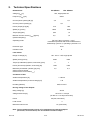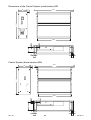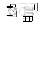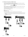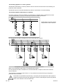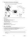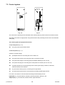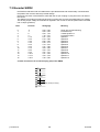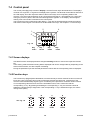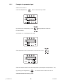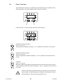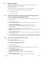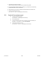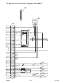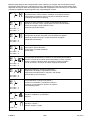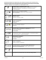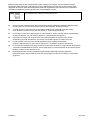
1
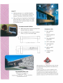
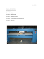
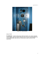
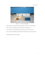
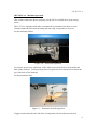
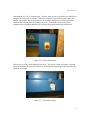
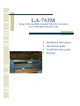
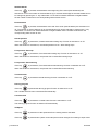
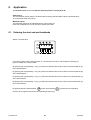
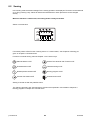
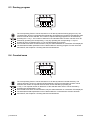
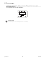
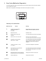
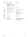
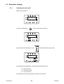
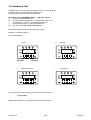
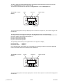
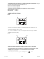
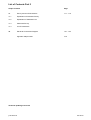
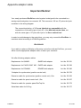
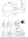
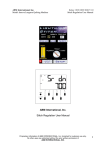
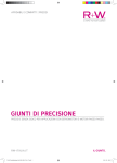
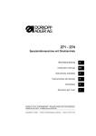
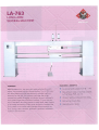
LA-763: V1.1
TABLE OF CONTENTS:
Introduction
Section 1.0 – Safety
Section 2.0 - Machine Setup
Section 3.0 – Machine Operation
Section 4.0 – Troubleshooting guide and notebook
Section 5.0 – Parts List
Figure 0.1 – LA-763
1
LA-763: V1.1
Introduction
ABM International would like to thank you for the purchase of an LA-763 Long Arm
Sewing Machine. ABM is confident that this machine will meet or exceed your
expectations for cost, speed and durability.
If at anytime you experience problems with any of your ABM machines we ask that you
contact us - 24 hours a day by calling our service department at (281) 443-4440. We can
help you solve the problem quickly, and correctly. Your calls, questions, and comments
will in turn help us to perfect the quality of our products and services in the future.
Once again, we thank you for your purchase.
ABM International, Inc.
Joe Podolski
Vice President
Engineering Department
2
LA-763: V1.1
Section 1: Safety
1.0 Safety Introduction
As with the operation of all machinery, safe operation of the LA-763 is a major concern
of ABM International, Inc. The purpose of this section is to inform personnel of the safe
and prudent operation of an LA-763.
We have attempted to recommend the most effective methods and calculations to warn
against actions that could result in personal injury, or make equipment unsafe. It is
important to understand that ABM cannot anticipate, or list all conceivable safety
methods and warn of all the possible hazards. In the interest of promoting safety, ABM
advises that the operating personnel should always make sure that personal safety and the
safe operation of the machine will not be adversely affected by their actions.
It is imperative that the operating personnel of the LA-763 read and understand the
information in this manual before operating the machine.
1.1 Safety Policy Statement
The conservation of the assets of any company, which include the buildings, equipment,
supplies and inventories as well as personnel, must be and is the responsibility of all
levels of management. The purpose of a personnel and property conservation program is
to insure that all phases of management recognize that personnel and property
conservation are both inseparable parts of a company’s objective…to produce quality
products at the lowest possible cost.
Safety of personnel in every aspect must be of first consideration. The implementation of
a conservation program will eliminate human suffering and effectively lower the direct
and indirect costs resulting from employee injury. It will substantially reduce the
exposure and probability of damage and / or loss of company’s physical assets.
1.2 Safety Practices
The safety factors must be observed to ensure safe operation of the LA-763 .
1.
2.
3.
4.
5.
6.
Read and understand the operating instructions of the LA-763 before operating.
Use extreme caution when working around the LA-763 electrical controls.
Keep hands or other body parts away from the moving parts of the LA-763 .
Wear appropriate personal safety protection.
Stop the LA-763 immediately at any sign of malfunction or danger.
Do not crawl under or into the LA-763 for any reason during the operation of the
machine.
7. Do not reach into the LA-763 at any time during the operation of the machine.
8. Do not climb, walk, or stand on the LA-763 at any time.
9. Do not tamper with factory installed guards and or safety devices.
10. Never operate machinery without all ABM installed guards and safety devices
intact, and in working order.
3
LA-763: V1.1
11. Before starting the LA-763, ensure that no loose tools, bars or parts are lying in or
on any part of the machine.
12. Proper fire fighting equipment should be kept in good operating condition and
kept near in the event of fire.
13. Never attempt to service any of the pneumatic components until the unit is
relieved of all air pressure.
14. Do not wear loose clothing or jewelry when operating the LA-763.
15. Always keep hair from coming in contact with moving parts.
4
LA-763: V1.1
SECTION 2.0 – Machine Setup
The LA-763 ships fully tested ready to operate. As a result, this manual provides a
section on machine setup so that you can install the machine. Please read this manual in
its’ entirety and follow all ABM instructions, especially the inspections. Total setup time,
less power and air hook-up, should take approximately 1 hour.
SETUP INSTRUCTIONS:
INSPECTION #1: Upon receipt of the machine, check to ensure that there is no visible
damage. Figure 0.1 and the front cover of this manual are enough for this inspection.
Note: that some components may be in different locations depending on the version
of the machine.
Determine the location in your facility for the sewing machine. Attach the eight (8)
machine legs supplied with the machine to the plates that were used to bolt the machine
to its skid. Level and position the machine in the desired location. Though not required,
ABM recommends that the machine be bolted to the floor. Place the foot pedal in front
of the machine on the floor and connect it.
Run a 220VAC line (15AMP) to the machine location. Though the machine does not
come equipped with a 220V plug, “ABM” does not recommend the use of any type of
extension cord to power the machine. As with any machine, power should be run
through approved conduit and ducting with proper termination. ABM does not supply a
main power disconnect with the machine and recommends that the customer install one.
You may connect the power to the machine at this time.
INSPECTION #2: Will confirm that the electronics of the LA-763 long arm sewing
machine are functioning properly.
WARNING: ELECTRICAL SHOCK HAZARD. THIS INSPECTION WILL
REQUIRE POWER TO BE ON WHILE THE ELECTRONICS CABINET IS
OPEN. IF A PROBLEM IS FOUND, YOU SHOULD NOT ATTEMPT TO
REPAIR IT WITH THE POWER ON. DISCONNECT THE MACHINE PRIOR
TO ADJUSTING ANY COMPONENTS WITHIN THE ELECTRICAL CABINET.
Step one; open the electronics cabinet located on the right vertical end-stand of the steel
bridge of the machine. The internals of the cabinet will look like Figure 1.0. From top to
bottom the components are as follows: Lamp power supply, servo motor, servo motion
controller .
Upon power up, the sewhead needles up.
5
LA-763: V1.1
Figure 2.0 – Electrical Panel.
FINAL TEST:
WARNING – WHEN OPERATING THE MACHINE, YOU MUST ENSURE
THAT THERE ARE NO LOOSE ITEMS SUCH AS TOOLS FOOD DRINKS ETC.
ON THE MACHINE AND THAT ALL PESONNEL ARE CLEAR OF THE
MACHINE.
6
LA-763: V1.1
Figure 2.1 – LA-763 sewing head.
Inspect the front of the machine and ensure that the sewhead is free of obstructions.
Step 1: Depress the treddle forward and the sewhead will begin to run.
Step 2: Release the treddle and the needle will stay down to pivot your fabric.
Step 3: Depress the treddle backwards and the needle will raise to the upper position.
Setup and inspection is now complete.
7
LA-763: V1.1
SECTION 3.0 – Machine Operation
This section will discuss how to properly use the LA763 to fulfill all of your sewing
needs.
The LA-763 is equipped with either a mechanical or pneumatic foot lifter to create
clearance under the foot when inserting and removing your product to be sewn.
For the mechanical lifter:
Figure 3.0 – Foot Lifter Operation.
To raise the presser foot, pull down on the white presser foot lift lever at located at the
back of the sewhead. To release the presser foot, pull the silver release bar located at the
top of the back of the sewhead.
For the pneumatic lifter:
Figure 3.1 – Pneumatic foot lift Operation
Toggle switch mounted to the left of the sewing head will raise and lower the foot.
8
LA-763: V1.1
Operating the LA-763 is a simple task. Turn the main power on and allow the machine to
energize (this may take 5 seconds). While the machine is powered on please make sure
that the foot pedal is not being pressed or the machine will activate an electrical safety
measure that will not allow the sewhead to work. To reset the safety, turn off the
machine remove anything that may be activating the pedal and turn the machine on.
Figure 3.2 – Power Disconnect
The speed of sewing can be adjusted two ways. The first is via the foot pedal. Pressing
the pedal further will cause the machine to speed up and releasing pressure will make the
machine slow down.
Figure 3.3 – Foot pedal control
9
LA-763: V1.1
Speed can also be limited on the servo controller interface. Press the TE SPEED button
until the menu with speed is shown. Press the four lower arrow keys to increase or
decrease the desired maximum speed. When modification is complete, press TE SPEED
to store the number in memory.
Figure 3.5 – Servo motor controller interface
10
LA-763: V1.1
SECTION 4.0 – Troubleshooting guide
ABM has done its best to include as much information as possible. However, not all
problems are listed, therefore ABM asks that whenever a problem occurs you contact a
service technician at our home office. To reach service dial 281-443-4440 and ask for a
service technician, they are on call 24 hours a day, seven days a week.
Troubleshooting notes:
A few blank pages are provided so that you and your personnel can keep records and
notes of machine problems. By using this section and keeping it attached to the manual,
you will always have your own personalized quick reference repair section.
11
LA-763: V1.1
TROUBLESHOOTING NOTES:
Date
Problem
Solution
12
LA-763: V1.1
TROUBLESHOOTING NOTES:
Date
Problem
Solution
13
LA-763M
Long Arm machine manual: Electric versions
www.abminternational.com
Installation instructions
Operational guide
Troubleshooting guide
Parts list
Table of Contents
Section 1.0 Section 2.0 Section 3.0 -
Machine Operation Guide
Troubleshooting guide
Parts List
EcoDrive
QE3760/QE5540
Instruction Manual
Part 1
QUICK-ROTAN Elektromotoren GmbH
Königstraße 154
67655 Kaiserslautern
Tel: 0631 / 200 38 80
Fax: 0631 / 200 38 62
E-Mail: [email protected]
www.quick-rotan.com
English 2004-03-10
The
symbol confirms that the respective drive system meets the
applicable safety requirements of the following EU directives:
- EC Maschine Directive 89/392/EWG
- EMV Directive 89/336/EWG
- Low Voltage Directive 73/23/EWG
ed-1-en
04-03-10
Contents
Page
Part 1
1.
General Safety Information
1.1 - 1.2
2.
Technical Specifications
2.1 - 2.3
3.
Range of Application
3.1
4.
Scope of Supply
3.1
5.
Transport and Storage
3.1
6.
6.1
6.2
6.3
6.4
6.5
Mounting Instructions
Mounting of the Motor
Adjustment of the motor and machine
Electrical connection
Preventive Action Against Electrostatic Charges
Mounting of Speed Control Unit (SWG)
6.1 - 6.7
Part 2
7.
Construction and Description of the EcoDrive Drive System
8.
Application
9.
Programming by the User
10.
Start of Operation
Part 3
11.
Survey and List of Parameters
12.
Electrical Connections Diagram
Technical updatings reserved !
ed-1-en
04-03-10
1.
General Safety Information
This EcoDrive Sewing Drive System has been constructed and tested in compliance with the relevant
regulations and safety standards and has left our factory in proper safety condition.
In order to maintain this condition and to ensure non-hazardous operation, the user is obliged to
observe the information and warning notes contained in this Operating Instructions Manual.
The EcoDrive is not a ready-to-use machine, but is designed for installation into machines of the sewingthread processing industry operating in clean and dry localities. It is not allowed to operate the
EcoDrive in any machine unless the machine destined for receiving installation of this motor is
specifically identified as being in compliance with the regulations of the EC Rule on machines.
Any application or use beyond the conditions stipulated above, such as outdoors, in moist or explosion
hazardous environment, is not considered to be in compliance with specifications. Application in
compliance with regulations and standards also includes close observation of the operating, maintenance
and repair conditions stipulated by the manufacturer.
The EcoDrive can function safely and reliably only when used in compliance with this Operating
Instructions Manual and in compliance with the use it is intended for.
Read this Operating Instructions Manual thoroughly before unpacking and commissioning the ECODRIVE. Please make yourself acquainted with all safety, installation. operating and maintenance
instructions before starting operation of the EcoDrive, its accessories and attachments.
Any and all activities on and by means of the EcoDrive must be carried out exclusively under close
observation of the general and specific safety instructions given in the ensuing sections of this
Operating Instructions Manual!
All persons involved must be made thoroughly familiar with these safety instructions, requiring them to
observe these closely. Non-observation of these safety instructions can cause injury to persons,
damage to objects or malfunction of or damage to the drive system itself.
Any and all accident prevention regulations as well as the rules on work in compliance with proper
practices and safety standards valid in the user country involved must be fully observed. This drive
system is subject to installation and commissioning by properly trained personnel!
Installation and commissioning of the EcoDrive must be made with due care by qualified technicians so
as to minimize the effects of any disturbing influences which are likely to constitute health hazards to
personnel or any other perilous condition.
Doing any work on any parts or elements of the equipment being under live voltage is not permitted!
Exceptions are subject to EN 50110.
Before removing any cover parts or installing any attachments or accessories - such as speed control
unit, light barrier control etc. - switch the machine off, shut off physical connection with mains voltage,
and wait for the machine to come to complete stop. Do not open the control box before ten minutes have
elapsed!
In order to reduce any hazard of burns, fire, electrical shock, or injury, it is basically not permitted to make
any structural modifications or other changes on the EcoDrive.
It is not allowed to operate the equipment with any cover or protection elements removed!
Before leaving the workplace, turn the ON/OFF switch into its OFF position. In case of prolonged pauses
of operation, remove the mains plug from the wall oulet so as to safeguard the drive system against
being inadvertantly switched on again.
Any equipment or auxiliary facilities additionally connected to the control system of the EcoDrive are only
allowed to be operated on low voltage generated by a safety transformer!
Never use the drive system with its ventilation louvers clogged. Make sure that ventilation louvers are
unobstructed by fibres, lint, dust etc.
ed-1-en
1.1
04-03-10
Do not introduce or drop any objects, such as needles, into the ventilation louvers.
Keep your hands out of the area of moving parts!
Do not operate the EcoDrive when using aerosols (sprays) or oxygen!
This Operating Instructions Manual is an integral part of the EcoDrive and must be passed on with it in
case of change of ownership.
The instructions given in the sections below are destined for your own safety as well as for that of other
persons.
Warnings given in various section of this Operating Instructions Manual for the purpose of
preventing specific hazards of injury to persons or damage to the equipment are identified
by the symbol shown at left.
This symbol is a warning given on the EcoDrive, indicating dangerous voltage.
The EcoDrive is permitted to operate only in a properly functional protection earth system
in compliance with all local rules and regulations.
ed-1-en
1.2
04-03-10
2.
Technical Specifications
Rated Values:
ED QE3760
Voltage (UN) [V]
EDL QE5540
230, single phase AC
Frequency (fN) [cps]
50/60
Current (drive system) (IN) [A]
3,5
5,0
Current (control system) [A]
0,6
Power (output) (P2) [W]
375
550
Speed (nn) [1/min]
6000
4000
Torque (Mn) [Nm]
0,63
1,2
Moment of motor inertia (Jmot) [kgcm²]
(without belt pulley)
0,5
1,0
Operating mode
S5 (40 % duty cycle at ts = 2.5 s)
Intermittent operation with electrical brake action,
relative duty cycle 40 %, operating cycle time 2.5 s
Protection type
IP40
Insulation class
E
Limit Values
Range of voltage [V]
190 - 240 +/- 10% single phase
Speed (n
) [1/min]
max
9000
Torque (accelleration) (Mmax, short-time) [Nm]
Power (short-time) (P2max, short-time) [W]
Maximum permissible (Jmasch) [kg cm²]
sewing machine inertia,
reduced to the motor shaft (Jmach)
4500
3
7
1000
1500
4,5
9,0
Conditions of Use
Ambient temperature [°C]
+ 5 bis 45
Ambient temperature (24 hour average) [°C]
< 35
Humidity (relative)
85% bei 30 °C
Driving voltage of the Outputs
Idling voltage [V]
25 DC
Voltage under load [V]
24 DC at I = 4 amps
(20 DC at I = 10 amps short-time)
Power
96 (200, short-time)
Load current
4
Maximum load current
10, (short-time)
Note: The accumulated load currents of all simultaneously operated outputs
(solenoids, solenoid valves) are not allowed to exceed 4 amps!
ed-1-en
2.1
04-03-10
Dimensions of the Control System (small version) ED
350,4
254,2
2
80
50
5,5
11
290,4
10
10
20
20
350,4
Control System (broad version) EDx
350,4
254,2
2
107
290,4
77
5,5
11
290,4
10
10
20
ed-1-en
20
2.2
04-03-10
Motor
l1
50
80
15
l2
80
ed-1-en
2.3
MS
MSL
l1 =
179
219
l2 =
147,5
187,5
04-03-10
3. Range of Application
The EcoDrive is not a ready-to use machine, but is intended for installation into other machines, such
as sewing units and sewing equipment used by the sewing thread processing industry.
The EcoDrive is destined for use in clean and dry localities.
Any application or use beyond the conditions stipulated above, such as outdoors, in moist or explosionhazardous environment, is not considered to be in compliance with specifications.
Application in compliance with regulations and standards also includes close observation of the operating,
maintenance and repair conditions stipulated by the manufacturer.
4. Scope of Supply
1x
Synchronous motor QE3760 with commutation transmitter
or Synchronous motor QE5540 with commutation transmitter
1x
Control system with mains power switch
1x
Speed control unit SWG2 (Art.Nr.63.012) + accessories
1x
Operating Instructions Manual
Optional:
1
Synchronizer (Art.Nr. 62.055)
1
Operator panel EcoTop
5. Transport and Storage
The EcoDrive has left our factory after thorough final inspection.
Please check the drive system for any transport damages.
If necessary, file claims with the carrier.
Complaints for missing parts will be accepted within 14 days from the date of purchase.
The EcoDrive and its accessories are shipped in a carton with polyurethane insert;
outside dimensions:
L = 600 mm,
W = 405 mm
H = 280 mm
This packing material protects the EcoDrive against outside influences during
transport and storage.
The EcoDrive is designed to withstand temperatures during transport and storage
of between -25°C and +55°C and briefly, but not lon ger than 24 hours, up to +70°C.
Storage in the packing material must be in a dry environment.
Handle the carton and its contents with care!
ed-1-en
3.1
04-03-10
6. Mounting Instructions
Before starting installation, please remove all parts from the packing material.
The carton holds the EcoDrive, accessories and Operating Instruction manual.
Check the content if complete.
If you have any questions with the installation, not clarified through the Instruction Manual,
please contact us or one of our nearest Service Stations.
Assemble the EcoDrive in compliance with the instructions and illustrations.
6.1 Motor assembly
There are three different ways to assemble the motor to the machine.
1.Machine head mount (rear / external)
2.Under the table top mount
3.Machine head mount (direct drive, internal)
There are three different ways to transmit the motor drive:
· Timing belt and timing gears.
· “V” belt and pulley.
· Direct drive on main shaft.
6.1.1 Use of timing belt.
Transmitting torque through timing belt, slippage is avoided.
Transmission ratio between motor and machine is 1:1.
Being so, no reference signal from sewing machine is required.
Many transmission ratios in both directions are possible,
on the available timing belt wheels.
In this case a reference position signal is needed by the machine.
6.1.2 Use of “V” belt
Transmitting torque through “V” belt, slippage is possible. Transmission ratio between motor and
machine is variable. Reference signal from sewing machine is required.
6.1.3 Assembly of the motor to the machine head.
Following, list of parts required:
- Assembly bracket (machine type related)
- Motor timing gear
- Machine timing gear
- Timing belt
- Belt cover
6.1.4 Assembly of the motor under the table
Following list of parts required:
- Assembly bracket
- Motor pulley
- Machine pulley
- “V” belt
- Belt cover
- If necessary synchronizer PD3
- Y-adapter
ed-1-en
6.1
04-03-10
6.2 Motor and machine adjustment
a)
Adjust motor shaft to reference position (zero position)
- Terminal box at top (viewpoint)
- Motor shaft groove (-90°) quarter to twelve in re lation to terminal
box equals zero position, rotate motor shaft.
b)
Adjust machine reference position (zero position)
- Rotate machine pulley (sewing rotation) until needle point starts
penetrating needle hole of throat plate (zero position)
c)
Assembly of timing belt
- Slide belt to motor and machine timing gear maintain and guarantee
positions described in a) and b).
ed-1-en
6.2
04-03-10
6.3 Electrical Connection (to Mains Power)
All work on the electrical equipment (connection, maintenance, repair) is permitted to be performed
only by or under the supervision of a properly qualified technician.
The EcoDrive is designed for connection to an earthed AC mains power system having a rated voltage
between
190 and 240 Volts, 50/60 cps.
Before connecting the power supply line, make sure that your mains power voltage is within the rated
voltage range specified on the nameplate of the EcoDrive.
Connection to mains power is permitted only by means of a multi-contact plug with protection earth
contact. Fixed connection is not permitted.
Connect the following potentials:
Phase
(L1 or L2 or L3)
Neutral conductor (N)
Protection earth (PE)
The EcoDrive is designed for connection to the following types of mains power systems:
- TN (system with a directly earthed point and with a protection earth conductor (PE) connected to this
point)
- TT (system with a directly earthed point, the protection earth conductor (PE) not being connected to
this point)
- IT (system not directly earthed)
IT-System
TT-System
TN-System
ed-1-en
6.3
04-03-10
The following applies to TT and IT systems:
All elements protected by a common protective device must be connected to the same earthing via
protection earth conductors.
All elements apt to be touched simultaneously must be connected to a common earthing.
The following applies additionally to IT systems:
No active conductor within the installation is permitted to be earthed directly. All elements must be
connected individually, in groups, or in total with a protection earthing conductor.
Single-phase connector system
with protection earth conductor
Do not operate more than 5 EcoDrives on one circuit fused with 16 amps.
Threephase connector system with protection earth conductor
Make sure to distribute loads evenly in a threephase AC system!
Do not operate more than 3 EcoDrives on one face fused with 16 amps in order not to overload
the N-conductor!
The EcoDrive is a protection class I device, i.e. for protection at indirect touching it comprises a
protection earth connection.
The EcoDrive is permitted to operate only in a properly functional protection earth system in
compliance with all local rules and regulations in order to avoid danger to persons by electric
shock or fire hazards in case of malfunction.
ed-1-en
6.4
04-03-10
It is not permitted to disable the protection system by using extension cables not equipped with a
protection earth conductor.
Caution:
Any interruption of the protection earth conductor within the EcoDrive or outside, or by
disconnecting the protection earth connection, can result in making the equipment
hazardous.
Any intentional interruption is inadmissible.
Fault Current Protection Devices
If any EcoDrives are to be monitored via fault current protection devices, then the latter must be shock
puls proof, short pulse delayed as well as suited for alternating and pulsating constant fault currents.
For connections, use line types not lighter than plastic- insulated sheathed flexible cables H05 VV.
The minimum conductor cross section must be 1 mm2, with the line length not in excess of 5 m.
The voltage drop in the protection earth conductor is not permitted to exceed 3.3 V at a measuring
current of 10 amps.
Any lines installed must be properly protected against anticipated loads and must be properly fastened.
Place and attach lines so as to maintain a minimum distance of 25 mm relative to any moving parts.
Place lines, mains power leads and low voltage circuits at a proper distance from each other to achieve
adequate separation.
For replacement make sure to use exclusively fuses of the type and current rating specified.
Any bridging-over of fuses is inadmissible and will create electrical or fire hazards.
If there is reason to presume that operation without hazards will not be possible, discontinue operation of
the drive system and safeguard the equipment against inadvertant use.
Reasons to presume that operation without hazards will not be possible are as follows:
-
if the drive system presents visible damage, for instance mains power connection cable,
-
if the drive system fails to function,
-
after lengthy storage at unfavourable conditions.
The control box may be opened only by properly qualified personnel and after having separated the drive
system from mains power by pulling the plug out. (After switching the system off, wait at least 10
minutes.)
Insert and lock carefully the connectors on the control system after having checked the pin and socket
configuration and the plug-in direction, to avoid malfunction.
The brake action will not be initiated when mains power supply is switched off or power failure occurs
during operation of the EcoDrive.
When leaving the workplace or when doing maintenance work, separate the machine from
mains power by pulling out the plug. For this, do not pull at the cable, but grip the plug and pull it
out.
Before separating the EcoDrive from mains power,
bring all control elements into „OFF“ or „0“ position.
ed-1-en
6.5
04-03-10
6.4 Electro-Magnetic Compatibility (EMC)
The EcoDrive is designed for installation/attachment to EMC sewing units and equipment, i.e. it complies
with the relevant EMC regulations (CDV IEC 204-3-1 44 sec 169) for a cable length of 500 mm at each
input or output connector. In accordance with experience, this is adequate for sewing units.
More complicated sewing equipment may require additional action due to longer cables, unfavourable
cable placement, neighbouring strong interference fields etc.
The following action can be appropriate for reducing or eliminating interference:
-
The use of appropriate filters, delay units, line material or line placement.
-
Lines belonging to different circuits (such as mains power, low voltage) being placed at a proper
distance from each other to minimize interference.
-
Reference potential conductors for the circuits, or a common connection point:
star-type wiring with one or more reference points earthed via insulated conductors having a large
cross section.
-
Electrically conductive parts of the sewing unit or equipment should be connected via potential
compensation leads to the protection earth conductor on the EcoDrive control box. (Use leads suited
for high frequencies: fine-gauge stranded leads with a cross section of at least 2.5 mm2, or largearea copper bands.)
When connecting potential compensation leads, make sure to achieve good contact, i.e. use toothed
washers for connections to painted parts.
Include the following parts in potential compensation:
- sewing machine head
- sewing machine stand
- treadle
- housings of solenoids or solenoid valves
- holding brackets for push-button switches
- stands for stackers, band feeders etc.
-
Mass Connections
Lead mass connection lines from each equipment element to a common point.
Use large cross section braided leads between moving parts and casings while keeping mass
connection as short as possible.
-
Signal Transmission
Use electrostatic and magnetic screening, twisted conductors and appropriate line placement to
ensure that transmission of interference voltages from control or mains power lines to signal lines is
prevented.
(Right-angle line crossings are better than any lower angles; by all means avoid parallel
placement.)
-
Separation of Equipment Parts
Equipment parts that are susceptible to interference parts (pulse-processing and/or low-level
subassemblies) should be mounted separately from and/or be screened against switching devices
such as electromagnetic relays, thyristors etc.
-
Although being largely insusceptible to interference, the EcoDrive should not be operated in the
immediate vicinity of HF welding devices or similar equipment to avoid malfunction.
-
The EcoDrive is capable of complying with EMC regulations only when the control box front is
provided with its cover!
-
The covers of the control box must remain closed during operation in order to avoid malfunction due
to EMC causes as well as pollution by dust penetration.
Whenever trouble should occur, please contact the manufacturer.
ed-1-en
6.6
04-03-10
6.5 Mounting of the Speed Control Unit (SWG)
-
Attach the speed control unit by means of the mounting bracket under the machine table.
-
Connect the push/pull bar of the SWG with the machine treadle by means of a pitman rod.
-
Install the mounting bracket for the SWG in such a way that the pitman rod and the push/pull
bar of the speed control unit (SWG) line up to the treadle.
This guarantees a optimal force transmission from treadle to SWG.
-
The pitman rod and the treadle should form an angle as close to 90 degrees as possible.
-
The speed control unit can be swivelled on the control box within a range of 40 degrees.
-
Make sure that the treadle can move with ease!
ed-1-en
6.7
04-03-10
EcoDrive
QE3760/QE5540
Type
P40ED
Instruction Manual
Part 2
QUICK-ROTAN Elektromotoren GmbH
Königstraße 154
67655 Kaiserslautern
Tel: 0631 / 200 38 80
Fax: 0631 / 200 38 62
E-Mail: [email protected]
www.quick-rotan.com
Englisch 2004-03-08
List of Contents Part 2
Chapt.
Contents
Page
7.
7.1
7.2
7.3
7.4
Description of the EcoDrive drive system
Motor QE3760 / QE5540
Control system
Speed control unit SWG2
Control panel S1
7.1 - 7.5
8.
8.1
8.2
8.3
8.4
8.5
Application
Entering the start and end backtacks
Sewing
Darning program
Counted seam
Error Messages
8.1 - 8.4
9.
9.1
9.1.1
9.1.2
9.2
Error codes (malfunction diagnostics)
Parameter settings
Selecting the user level
Example of a parameter input
Reset / Cold start
9.1 - 9.5
10.
10.1
Start of operation
Control of the direction of rotation and of the reference position from
the needle bar (needle position NPO)
Control of the needle positions NP1 / NP2
Control of the maximum speed
Hardware test
10.1 - 10.5
10.2
10.3
10.4
Technical updatings reserved!
p-40-ed-2-en
04-03-08
7. Description of the EcoDrive Drive System
The EcoDrive Drive System is an electronically commutated, brushless DC motor.
The system is composed of the following subassemblies
X1
Fig.7.2
X2
Fig.7.1
3 3 3 3
A
B
C
Fig.7.4
Fig.7.5
Fig.7.3
Motor QE3760 / QE5540 (Fig.7.1) with integrated optoelectronic incremental encoder for commutation
and positioning.
Control (Fig.7.2) with
- mains connection with interference rejection circuit
- electronically controlled combinational circuit
- intermediate DC circuit
- motor-driven current inverter
- electronic control for motor control and machine specific functions
- connection for a sewing light
Speed control unit SWG2 (Fig.7.3)
Control panel S1 (Fig.7.4)
Mains switch located under the desktop table (Fig.7.5)
7.1 Motor QE3760/QE5540
The motor is a synchronous motor. It has a permanent-magnetic rotor, a stator with three-phase winding
and an optoelectronic increment encoder for commutation and positioning.
The rated capacity of the motor (shaft capacity) is 375W (QE3760), 550W (QE5540) in S5 mode.
The rated speed of the motor is 6000 rpm (QE3760), 4000 rpm (QE5540),
the maximum speed is 9000 rpm (QE3760), 4500 rpm (QE5540).
The motor has two mains leads:
a)
b)
four-wire with special quadripolar AMP plug (X1 Fig.7.1) for connecting the stator coil to the control
system
six-wire shielded with nine-pole D-sub plug (X2 Fig.7.2) for connecting the increment encoder to the
control system.
p-40-ed-2-en
7.1
04-03-08
7.2 Control system
X0
Fig. 7.6
Fig 7.7
The control box is attached to the underside of the machine table by means of the four enclosed screws.
The mains connection is single-phase, using the three-wire cord protruding from the rear and a standard
safety plug.
The control system has peripheral functions:
on the front panel (Fig. 7.6):
X0
nine-pole D-sub jack for data transfer
on the rear panel (Fig. 7.7):
sockets or connector plugs
X1
quadripole socket for connecting the motor’s stator coil
X2
nine-pole D-sub jack for connecting the motor’s increment encoder
X3
nine-pole D-sub plug for connecting set point adjuster SWG2 (Art. No. 63.012)
X4
nine-pole D-sub plug for connecting the control panel OC-TOP/AP (Art. No. 64.175)
X5
37-pole D-sub jack for connecting the process control system (keys, switches, solenoids,
solenoid valves) on the machine.
X6
six-pole RJ45 western jack for connecting from a light barrier
X7
six-pole RJ45 western jack for connecting from a bobbin thread supply monitor
In function, the control is connected with the sewing machine/sewing unit via:
Inputs (Ex), e.g. for push-buttons, switches, proximity switches, detectors, and
Outputs (Ax), e.g. for solenoids, solenoid valves, signal indicators.
p-40-ed-2-en
7.2
04-03-08
7.3 Encoder SWG2
the SWG2 is attached under the table with the provided bracket and mechanically connected with
the pedal of the machine with the provided linkage.
Electrical connection of the SWG2 is made with the nin-pin coupling on plug X3 on the rear side of
the control.
The SWG2 is an analog mechanical-electrical converter that converts the pedal stroke into voltage.
This analog output voltage of the SWG2 is digitised in the control so that the pedal stroke is divided
into 16 steps (positions).
Level
0
1
2
3
4
5
6
7
8
9
10
11
12
13
14
15
Position
Voltage [V]
Meaning
-2
-1
0
+1
+1 D
+2 D
+3 D
+4 D
+5 D
+6 D
+7 D
+8 D
+9 D
+10 D
+11 D
+12 D
0,00 - 0,50
0,50 - 0,94
0,94 - 1,76
1,76 - 2,21
2,21 - 2,43
2,43 - 2,66
2,66 - 2,90
2,90 - 3,13
3,13 - 3,37
3,37 - 3,60
3,60 - 3,84
3,84 - 4,07
4,07 - 4,31
4,31 - 4,54
4,54 - 4,78
4,78 - 5,00
Seam end, thread trimming
Presserfoot up
Treadle position 0
Presserfoot down
Speed n1
Speed n2
Speed n3
Speed n4
Speed n5
Speed n6
Speed n7
Speed n8
Speed n9
Speed n10
Speed n11
Speed n12
contact connections of connection plug (X3) of the SWG2
1
2
3
4
5 +5V
6
7
8 0 … 5V SW (analogue voltage)
9
p-40-ed-2-en
0V
7.3
04-03-08
7.4 Control panel
The control panel (Fig. 7.8) consists of display 1 and the function keys described below. The display 1
consists of a single-line, 7 segment LCD display with 8 symbols. The texts 2, located above and next to
the LCD display, show the respective status of the function keys and the operating status of the
machine. The control panel switches on all LCD-segments and the horn automatically for a short time
during the power-on phase, after which the lettering PFAFF appears on the display, until the higherranking control unit sends commands to the control panel.
The function keys are located around the display 1. They are foil-packed without permanent marking
and without contact signal. Fixed functions are allocated to the keys, see Chapter 7.4.2 Fuction keys.
2
4
1
3
SPEED
TE
3
3
A
B
ERROR
3
C
3
D
Fig. 7.8
Key
field 1
Key
field 2
Key
field 3
Key
field 4
7.4.1 Screen displays
Activated functions are displayed with a triangular marking 3 below or next to the respective function
key.
In the sewing mode all relevant sewing data is displayed and can be changed directly, depending on the
status of the machine, see also Chapter 8.2 Sewing.
During the parameter input the selected parameter number with the corresponding value is displayed.
7.4.2 Function keys
The function keys (Fig.7.8) described below are used basically to switch machine functions on and off.
Each time a key is pressed, this must be confirmed by at least one beep tone. Irrespective of the
machine mode a double beep signal is given if invalid keys are pressed or maximum values reached.
If a corresponding value has to be set for the activated function, this is carried out with the
corresponding +/- key. By pressing and holding the corresponding +/- key, the relevant numerical
value 4 is changed slowly to begin with. If the corresponding +/- key is held down longer, the values
change more quickly.
A
B
C
D
Key
field 1
Key
field 2
Key
field 3
Key
field 4
see Fig. 7.8
p-40-ed-2-en
7.4
04-03-08
Start backtacks
is pressed, the backtacks at the beginning of the seam (start backtacks) are
If this key
switched on or off. The number of forward stitches (A) or reverse stitches (B) for the start backtacks can
be changed by pressing the +/- key underneath. To convert from double backtack to single backtack
set the number of stitches for the corresponding seam section at zero.
End backtacks
is pressed, the backtacks at the end of the seam (end backtacks) are switched on or
If this key
off. The number of reverse stitches (C) or forward stitches (D) can be changed by pressing the +/- key
underneath. To convert from double backtack to single backtack set the number of stitches for the
corresponding seam section at zero.
Needle position
If this key
is pressed the „needle raised after sewing stop“ function is switched on or off.
When the function is switched on, the needle positions at t.d.c. after sewing stops.
Foot position after stop
If this key
is pressed the „foot raised after sewing stop“ function is switched on or off.
When the function is switched on, the presser foot is raised after sewing stops.
Foot position after trimming
is pressed the „foot raised after thread trimming“ function is switched on or off.
If this key
When the function is switched on, the presser foot is raised after thread trimming.
Thread trimmer
If this key
is pressed the thread trimming function is switched on or off.
Darning program
If this key
is pressed the darning program function is switched on or off.
The counted seam function is switched off automatically.
Counted seam
If this key
is pressed the counted seam function is switched on or off.
The darning program function is switched off automatically.
TE/Speed
If this key
is pressed once the speed limit for the sewing mode is activated.
If this key
is pressed twice (within 5 seconds) the machine changes from sewing to input mode.
p-40-ed-2-en
7.5
04-03-08
8.
Application
This EcoDrive drive can be used with the external operator’s control panel S1.
Switching on
The on/off switch (mains switch) is located under the sewing machine table. When activated and live,
an control lamp at the switch lit up.
Maximum speed
The maximum speed can be adjusted with the control panel S1.
Press the TE/Speed key once to call up the speed input mode.
8.1
Entering the start and end backtacks
Switch on the machine.
SPEED
TE
3
A
ERROR
3
B
3
C
3
D
If necessary switch off the "darning seam" or "counted seam" function, see Chapter 8.3 Darning pro
gram or Chapter 8.4 Counted seam.
By pressing the corresponding +/- key ("A") select the desired value for the number of forward stitches (A)
of the start backtack.
By pressing the corresponding +/- key ("B") select the desired value for the number of reverse stitches (B)
of the start backtack.
By pressing the corresponding +/- key ("C") select the desired value for the number of reverse stitches (C)
of the end backtack.
By pressing the corresponding +/- key ("D") select the desired value for the number of forward stitches (D)
of the end backtack.
By pressing the keys start backtack
and/or end backtack
, activate the corresponding
function (arrow appears next to the corresponding function key).
p-40-ed-2-en
8.1
04-03-08
8.2
Sewing
In the sewing mode all relevant settings for the sewing operation are displayed. Functions can be switched
on or off by pressing a key. Values for start and end backtacks or stitch placement can be changed
directly.
When the machine is switched on, the sewing mode is always activated.
Switch on the machine.
SPEED
3
A
TE
ERROR
3
B
3
C
3
D
If necessary switch off the function "darning seam" or "counted seam", see Chapter 8.3 Darning program or Chapter 8.4 Counted seam.
Functions in manual sewing, also see Chapter 7.4.2 Function keys:
Start backtacks on/off
Presser foot raised at end of seam on/off
End backtacks on/off
Thread trimming on/off
Needle position raised on/off
Darning program on/off
Presser foot raised on/off
Counted seam on/off
Sewing is carried out with the pedal functions.
The "Darning program" and "Counted seam" functions are explained in more detail in Chapter 8.3
Darning program or Chapter 8.4 Counted seam.
p-40-ed-2-en
8.2
04-03-08
8.3 Darning program
1 5 1 5
A
B
5
1
C
1
The corresponding function can be switched on or off directly with the Darning program key. The
"counted seam" function is switched off automatically. Several darning programs with different seam
sections A and B can be selected. The number of required darning programs can be selected by
operating the +/- key 1. The number of stitches for the individual seam sections A and/or B can be
selected by operating the corresponding +/- key. By operating the corresponding +/- key it is
possible to select a repeating factor "C" for the selected darning program.
If the backtack functions are also activated, only the status backtack on or backtack off is displayed.
The individual backtack parameters can be altered after the "darning program" function has been
switched off, see Chapter 8.1 Entering start and end backtacks.
8.4 Counted seam
1 6 0
A
B
1
C
1
The corresponding function can be switched on or off directly with the Counted seam key. The
"darning program" function is switched off automatically. Several counted seam sections can be
selected. The number of required seam sections can be selected by operating the
+/- key 1. The required number of stitches"A" of the selected seam section can be selected by
operating the corresponding +/- key.
If the backtack functions are also activated, only the status backtack on or backtack off is displayed.
The individual backtack parameters can be altered after the "counted seam" function has been
switched off, see Chapter 8.1 Entering start and end backtacks.
p-40-ed-2-en
8.3
04-03-08
8.5 Error messages
If a fault occurs, the text "ERROR" appears on the display, together with an error code and short
instructions. An error message is caused by incorrect settings, faulty elements or seam programs as well
as by overload conditions.
For an explanation of the error codes see Chapter 9.
ERROR
E
9
Correct the error.
Acknowledge error correction by pressing the TE/Speed key.
p-40-ed-2-en
8.4
04-03-08
9
Error Codes (Malfunction Diagnostics)
The control system of the drive cyclically tests its own functional condition and the functional condition
of the complete drive system.
Malfunctions are signalled via the display of the external control panel, for instance:
ERROR
E
1
Summary of the malfunctions:
Malfunction-No.
Reason
Remedy
1
Treadle not in zero position
when mains power is
turned ON.
Bring treadle in zero position, check the
treadle, connect the Speed control unit.
9
Start lock is active.
Eliminate cause.
10
Machine class (<799>) was
changed.
Turn mains power switch OFF and ON again.
62
Short circuit on 24 V (32 V) DC.
Find short circuit and eliminate it
Turn mains power switch OFF and ON again.
63
Overload on 24 V (32 V) DC,
load current > 4 amps.
Turn mains power switch OFF and ON again
search component (magnet), what was the
reason why. Adjust new the magnet or
change it.
64
voltage too low (90 V - 150 V)
( U < 150V ).
let check the voltage from a specialist.
65
Power electronics not operational
after mains power ON,
mains power < 130V.
Turn mains power switch OFF and ON again,
if the malfunction still happens, then change
the control box.
66
Earth short (motor or motor supply line
has earth short in one or more phases).
Change the control box or the motor.
67
Internal malfunction
Change the control box.
p-40-ed-2-en
9.1
04-03-08
Malfunction-No.
Reason
Remedy
68
Power electronics shut-off
Eliminate cause.
when motor runs why:
a) Overcurrent, short circuit in motor or
supply line
b) Overvoltage, mains voltage too high (>300 V),
motor overloaded while decelerating
c) Undervoltage
70
Machine blocked, no increment from
synchronizer at max. motor torque.
Eliminate cause.
71
Commutation transmitter plug not inserted
Insert commutation transmitter plug
73
Motor overloaded.
Eliminate cause.
75
Internal malfunction: governor blocked.
Change control box.
92
Start lock while motor running.
Eliminate the causing input signal
and turn mains power switch OFF
and ON again.
93
Wrong EEPROM.
Change EEPROM.
Internal malfunction.
Change control box.
Governor disturbance:
Startangle within control
time not reached.
Turn hand wheel into needle position 2
(link take-up up), turn mains power switch OFF
and ON again, start new.
Raise value for parameter <880>
100
111
173
p-40-ed-2-en
9.2
04-03-08
9.1 Parameter settings
9.1.1
Selecting the user level
Switch on the machine.
3
A
3
B
3
C
Press the TE/Speed key
3
D
twice to call up the input mode.
TE
1 0 1
o n
A
By pressing the corresponding +/- key
select the parameter group "798".
TE
7 98
0
A
By pressing the corresponding +/- key select the desired user level:
"0" = operator level A
"1" = technician level B
"11" = service level C
The selected user level is displayed on the screen. (see arrow).
p-40-ed-2-en
9.3
04-03-08
9.1.2
Example of a parameter input
Switch on the machine.
Press the TE/Speed key
twice to select the input mode.
TE
1 0 1
o n
A
By pressing the corresponding +/- key
the user level "B",
select parameter "798" and
see Chapter 9.1.1 Selecting the user level.
TE
7 98
0
B
Select parameter "607" by pressing the corresponding +/- key
TE
607 4000
B
Select the required value for the maximum speed by pressing the corresponding +/- key.
By pressing the TE/Speed key
the selected value is taken over and the
machine switches to the sewing mode.
p-40-ed-2-en
9.4
04-03-08
9.2
Reset / Cold start
After selecting the reset menu, by pressing the corresponding key it is possible to reset
seam parameters, reset seam programs and to execute a cold start.
D
A
Press and hold "+" on keys A and D and switch on the machine!
1
2
A
3
B
D
A
Resetting the seam parameters
Press "+"on key "A".
All parameters are deleted, the display "—rE—" appears for a short time on the screen.
B
Resetting the seam programs
Press "+"on key "B".
All seam programs are deleted, the display "—rE—nA" appears for a short time on the
screen.
D
Cold start
Press "+" on key "D".
With the exception of the value for the machine class, the values of the machine control
unit are set back to their basic values, the display "—COLd—" appears for a short time on
the screen.
After the cold start all programmed values are set back to their status at the
time of delivery. For this reason after a cold start it is necessary to re-enter
first the parameter "799" and then the parameter "700".
p-40-ed-2-en
9.5
04-03-08
10.
Start of operation
If the EcoDrive has been stored at a temperature of <+5°C, then a working temperature
of between +5°C and +40°C must first be obtained.
The equipment must be dry.
Before work with the machine can be started, make sure to perform the following:
a) Control the direction of rotation and the reference position of the needle bar
b) Control the needle positions
c) Control the maximum speed
10.1
Control of the direction of rotation and of the reference position
from the needle bar (needle position NPO)
a) Activate programming level „b“ (technician level) (see section 9.1.1 „Selecting the user level „b“)
b) Set parameter 700
c) Actuate treadle briefly forward:
Reaction: The machine performs a full revolution and then positions in a random position.
d) Is the direction of rotation correct?
When yes, then proceed to adjust the reference position, proceed with e) below
If no, then activate parameter 800 and change the value <800> (on → off or off → on)
than proceed as b)
e) Turn the handwheel of the machine in the direction of rotation until the
point of the needle coming from up to down touches the level of the throat plate (= reference
position).
f)
Actuate the treadle briefly forward:
Reaction: The machine performs one revolution and positions in the same position that had been
previously obtained by hand.
g) As soon as new parameter numbers are activated, or the programming level „b“ is negated, then
the parameter value <700> is memorized and the reference position adjustment is completed.
10.2
Control of the needle positions NP1 / NP2
NP1 - needle down position (<702>)
NP2 - thread take up lever in the up position (<703>)
a) Activate programming level „b“ (technician level)
(see section 9.1.1 „Selecting the user level „b“)
b) Activate parameter 702
c) Actuate the treadle briefly forward
Reaction: The machine performs a revolution and then positions at the programmed <702>
d) Is the needle position correct?
When yes, then proceed as with g) below.
When no, then the position must be changed
by turning the hand wheel or
via key field 3 +/- or field 4 +/- (see section 7.4.2) at the control panael S1
e) Actuate the treadle briefly forward
Reaction: The machine performs a revolution and positions in the same position
p-40-ed-2-en
10.1
04-03-08
f)
The position can again be corrected.
When no further correction is needed, then proceed as with g) below.
g) As soon as another parameter number is called up, e.g. example 703, the previously
programmed value of <702> is memorized.
h) With parameter 703 correction is obtained as described above for parameter 702.
i)
10.3
Deactivate programming level „b“
(see section 9.1.1 and 9.1.2 „Selecting the user level „b“).
Control of the maximum speed
p-40-ed-2-en
a)
Activate programming level „b“
(see section 9.1.1 "Selecting the user level „b“)
b)
Set to parameter 607
c)
Check the parameter value <607> and make correction if necessary via
key field 3 +/- or key field 4 +/- at the control panel S1
d)
Deactivate programming level „b“
(see section 9.1.1 and 9.1.2 "„Selecting the user level „b“).
10.2
04-03-08
10.4 Hardware Test
Hardware Test is a check routine permitting to use the control panel S1
for testing various components of the drive system
(control system) and of the machine installation.
Activation of the „HARDWARE TEST“ = „HW-Test“ routine
a)
push key TE-SPEED two times
b)
to activate programming level „c“ set parameter <798> to 11
(see section 9.1.1 and 9.1.2 „programming level „b“).
c)
at programming level „c“, call up parameter 797
d)
Set <797> from OFF to ON with key field 4
After that, the display shows the first test block: Inputs.
Response: The display shows:
Survey of test blocks:
1
Inputs
E
2
1
key field 1
3
0
A
1
0
key field 4
Speed controlunit
S
Outputs
4
0
Synchronizer
I
0
To call up the test blocks (advancing from test block to test block),
use key field 1
Hint: further indications on the display are for optional functions!
p-40-ed-2-en
10.3
04-03-08
To call up various functional elements within a test block such as advancing from an Input to the
next, use key field 2 +/- on the control panel S1.
To activate functional elements selected, use key field 4 +/- on the control panel S1.
Test block 1: Inputs
Display:
Input
Input no.
E
1
State of input
0
key field 4
The function assigned to the input displayed can be seen from chapter 12 „Connections Diagram for
Connectors“.
The designations E (for input) are located on the lefthand side of the connectors shown.
The keys or selectors assigned to the inputs are designated S in the connections diagram and have
the same numbers as the associated inputs, i.e.
key S1 is connected to input E1
key S2 is connected to input E2
key Sx is connected to input Ex.
The operating state of the input is signalled in the 7th digit of the display.
Key/switch open
→ display: 0
Key/switch closed → display: 1
In the righthand part of the display, the connecting plug and the pin number to which the displayed
input is connected are shown for the purpose of reference.
Test block 2: Outputs
Display:
Output
Output no.
A
1
State of output
0
The function assigned to the ouput displayed can be seen from chapter 12 „Connections Diagram for
Connectors“.
p-40-ed-2-en
10.4
04-03-08
The designations A (for output) are located on the lefthand side of the connectors shown.
The solenoids/solenoid valves assigned to the outputs are designated Y in the connections diagram
and have the same numbers as the associated outputs, i.e.
solenoid Y2 is connected to output A2
solenoid Y3 is connected to output A3
solenoid Yx is connected to output Ax
The operating state of the output displayed is signalled in the 7th digit of the display.
Output not activated → display: 0
Output activated
→ display: 1
To activate an output, use key field 4 +/-.
Test block 3: Speed control unit (SWG)
Display:
SWG
Value
S
0
The treadle can be actuated to operate consecutively all 16 steps of the speed control unit.
The following is displayed in digits 6, 7 and 8
-2 / -1 / 0 / +1 / 1D / 2D / … / 12D, when the speed control unit is in proper condition.
Test block 4: Synchronizer (IWG)
Display:
Value
IWG
I
236
This test block permits to check the synchronizer (increment encoder). For this purpose,
the shaft of the motor must be rotated manually.
The increments (pulses) of the synchronizer are counted and shown in display digits 4, 5 and 6.
This display runs from 0 through 255 when the synchronizer is in proper condition.
To deactivate the test routine,
turn the mains power switch OFF, or press the TE/Speed key
p-40-ed-2-en
10.5
twice.
04-03-08
EcoDrive
QE3760/QE5540
Type
P40ED
Instruction Manual
Part 3
QUICK-ROTAN Elektromotoren GmbH
Königstraße 154
67655 Kaiserslautern
Tel:
0631 / 200 38 80
Fax:
0631 / 200 38 62
E-Mail: [email protected]
www.quick-rotan.com
Englisch 2005-10-25
List of Contents Part 3
Chapt. Contents
Page
11.
Survey and List of Parameters
11.1 - 11.9
11.1
Explanation of Parameter Survey
11.2
Explanation of Parameter List
11.3
Parameter Survey
11.4
List of Parameters
12.
Electrical Connections Diagram
12.1 - 12.4
Appendix adaptor cable
12.5
Technical updatings reserved!
p-40-ed-3-en
05-10-25
11. Survey and List of Parameters
11.1 Explanation of Parameter Survey
The parameter survey is designed as an aid for finding parameters quickly. It is a summary of references
for the parameter list. Listed behind each reference are all parameters which exert an influence on the
function described by the reference.
The parameter survey is divided into five columns:
Column 1 shows the references (functions) to which parameters are assigned.
Column 2 shows the abbreviations of the respective functions.
Column 3 shows all parameters (setting numbers) belonging to the respective reference.
Column 4 shows, for each function (reference) which controls inputs or outputs, the applicable
indications such as Ex or Ax which can also be found on the connections diagram.
Column 5 shows, for each function (control inputs (Ex) or control outputs (Ax)), the respective
plugs with the number of contacts (see connections diagram).
Example for searching a parameter:
Keyword (function): inverse rotation
The parameter survey shows in column 3 the parameter numbers 618, 801.
Suppose that the inverse rotation function is to be enabled. The parameter list shows this function under
parameter number 618.
11.2 Explanation of Parameter List
The parameter list is divided into 5 columns. These comprise, in
column 1: the parameter number,
column 2: is the explanation (meaning) of the parameters and the coding system of row 1 of the keys
of the mini operator's panel, used when the parameter concerned can be programmed with
the mini operator's panel,
column 3: the programming level (A, B, C) on which the parameter in question can be accessed,
column 4: the range of values within which the parameter in question can be set,
column 5: the value of the parameter in question is set on delivery ex factory.
Parameters having "either/or" validity (software switches) can merely be set to value Ι or ΙΙ. In the case
of such parameters, column 4 is empty.
Parameter numbers in acute brackets; e.g. <105>, mean the value (content) set for the parameter
in question.
Example:
107 Speed for front backtack when <106> = I
I
limited by <105>
II
limited by <607>
Explanation:
Parameter 107 is valid only the the value (content) of parameter <106> = I.
If parameter 107 is set to I (<107> = I), then the speed for the front backtack is limited by parameter 105,
e.g. <105> = 1500. If parameter 107 is set to II (<107> = II), then the speed for the front backtack is
limited by the value of parameter 607, e.g. <607> = 4000.
p-40-ed-3-en
11.1
05-10-25
11.3 Parameter survey P40ED 1_040_10
(PARAM.ENO)
Function
Abbrev’n
Parameter
Accelerate
DRZAN
722
Backtack
RIE
105/107/110
364/391/523
584/585
Backtack inversion
RIV
748
Backtack suppression
RIUNT
748
Blower
BLA
668
Brake
DRZAB
723
Catcher
FANG
707
Chopper
MESSER
105/110
Control
REG
880/884/885
886/887/889
890/900
Decorative backtack
ZRIE
391/522/523
530/775
Defect search
HWT
797
Delay
VERZ
623/642/643
730/761/770
939
Direction of rotation
DRR
800
Display
ANZ
605/933
Edge trimmer
KS
356/387/776
End backtack
ER
110
Engine
MOT
897
Feed reverse
TUM
301/364/643
721/757/939
Front backtack
AR
105/106/107
Hardware test
HWT
797
Inverse rotation
RDR
618/623/801
Machine class
MAKL
799
Machine run
ML
387
Needle position
NAPO
522/700/702
703/705/706
707/710/746
748
p-40-ed-3-en
11.2
Input
Connection
Output Socket/Contacts
05-10-25
Needle position change-over
NPW
446/748
Needle up without trimming
NHOS
446/710/748
Number of stitches
STZA
111/112/470
760
ON period
EINZ
528/715/889
Operator panel
BDF
101
Photocell
LS
111/112/113
163/199/615
Presser foot
PF
356/636/642
651/719/729
730/770
Program
PR
203/206/311
313
Programming level C
EBC
798
Residual brake
STBR
718
Seam end
NE
110/206
Seam start
NA
105
Single stitch
EST
392/446/748
Soft start
SANL
116/117
Speed
DRZ
105/106/107
110/117/199
203/530/585
605/606/607
608/609/901
Speed decrease
DRZAB
723
Speed increase
DRZAN
722
Speed limitation
DB
585
Stacker
STAP
528/776
Start
START
113
Start delay
STVERZ
729
Stitch condensation
STVD
105/106/107
110/364
Stitchcounter
STZ
760
Stop
STOP
206
Stop time
STOPZ
775
Target stitch
PEIPO
653/789
Thread clamp
FK
470
p-40-ed-3-en
11.3
05-10-25
Thread monitor
FW
382/660/760
Thread puller
FZ
761
Thread tension release
FSL
393/538/636
707/761
Thread trimming
SN
311/609/646
705/706/734
901
Thread wiper
WI
668/715
Time needed to switch on
EINZ
528/715/889
Timing output
TA
538/642/643
705/719/721
734
Vacuum
SAUG
105/110/356
Zigzag machine
ZZ
746
p-40-ed-3-en
11.4
05-10-25
11.4
List of Parameters P40ED 1_040_10
No.
Function (Meaning)
101
(BDF) Audible signal of the control panel pushbutton A,B,C
1 = on
0 = off
(AR/RIE/DRZ/MESSER/NA/SAUG/STVD) Speed for B,C
front backtack/ stitch condensation
(AR/DRZ/STVD) Speed for front backtack/stitch
B,C
condensation
1
variable (treadle-controlled)
0
constant (corresponding to <105>)
(AR/RIE/DRZ/STVD) Speed for front backtack/stitch B,C
condensation when <106> = I
1
limited by <105>
0
limited by <607>
(ER/RIE/DRZ/MESSER/NE/SAUG/STVD) Speed for B,C
end backtack/ stitch condensation
(LS/STZA) Light barrier compensation stitches 1
A,B,C
(stitches from light barrier clear to seam end)
(LS/STZA) Number of stitches for light barrier fade-out
105
106
107
110
111
112
3, 4
113
116
117
163
199
203
206
301
311
313
356
364
382
387
(PARAM.EN)
Level
on knit fabrics (according to stitch size)
(LS/START) Start with light barrier
B,C
1
when light barrier is dark only
0
also when light barrier is clear
(SANL) Soft start stitches
A,B,C
(SANL/DRZ) Speed for soft start stitches
B,C
(LS) Sewing with photocell
B,C
1
yes
0
no
(DRZ/LS) Speed for light barrier compensation
B,C
stitches
(PR/DRZ) Speed for seam program
B,C
1
variable (treadle-controlled)
0
constant (corresponding to <221> or <222>)
(NE/PR/STOP) Interrupt/discontinue seam sections B,C
at speed = constant (<203> = II)
1
with treadle -2
0
with treadle 0
(TUM) Switch-on voltage of the magnet for transport C
change-over
1 24V
0 32V
(PR/SN) Cancellation of stitch count
B,C
1
with thread cutting
0
without thread cutting
(PR) Programs are backtack programs (darning
A,B,C
programs)
1
yes
0
no
(PF/SAUG/KS) Input E4 is at
B,C
1
Presser foot
0
Vacuuming
(RIE/STVD/TUM) Transport change-over means for B,C
1
Back-tack
0
Stitch condensation
(FW) Switching threshold of the analogue input for theB,C
thread monitor
(ML/KS) Output Ax (motor run) is active
B,C
1
With Pedal = 1D (Motor running)
0
With Pedal = 1 (Lower presser foot)
p-40-ed-3-en
11.5
Range
Values
of
Standard
Value
1
Kl. 1, 2, 3, 4
0300 - 2000 1200 Kl. 1, 3, 4
0300 - 2000 700 Kl. 2
0
Kl. 1, 2, 3, 4
0
Kl. 1, 2, 3, 4
0300 - 2000 1200 Kl. 1, 3, 4
0300 - 2000 700 Kl. 2
0001 - 0030 8
Kl. 1, 2, 3, 4
A,B,C
0000 - 0100 0 Kl. 1, 2,
0
0000 - 0030 0
0030 - 0640 400
0
Kl. 1, 2, 3, 4
Kl. 1, 2, 3, 4
Kl. 1, 2, 3, 4
Kl. 1, 2, 3, 4
0300 - 2000 1200 Kl. 1, 2, 3, 4
1
Kl. 1, 2, 3, 4
0
Kl. 1, 2, 3, 4
0
Kl. 1, 2, 3, 4
1
Kl. 1, 2, 3, 4
0
Kl. 1, 2, 3, 4
1
Kl. 1, 2, 3, 4
1
Kl. 1, 2, 3, 4
0000 - 0100 15
1
Kl. 1, 2, 3, 4
Kl. 1, 2, 3, 4
05-10-25
391
392
393
407
446
470
522
523
528
530
538
584
585
605
606
607
608
609
615
618
623
631
636
(ZRIE/RIE) single stitch-decorative backtack
1 = on
0 = off
(EST) Change-over to sinle stitch via treadle
1 = on
0 = off
(FSL) Thread tension release after seam end
1 = on
0 = off
Kein Kommentar vorhanden
(NHOS/NPW/EST) Input E2 is
1 = needle up without trimming
2 = needle position change-over
3 = single stitch
4 = single stitch with reduced length
5 = backtack inversion
6 = backtack suppression
7 = change-over position
8 = puller lift switched off
(STK/FK/STZA) number of stitches for disabling
thread gripper
(NAPO/ZRIE) Needle position when stop occurs
during decorative backtack (stitch in stitch)
1
position 2 (up)
0
position 1 (down)
(RIE/ZRIE) Backtack
1
decorative backtack (stitch in stitch)
0
standard backtack
(EINZ/STAP) Duration (ms) of stacker function
(DRZ/ZRIE) Speed (max.) for decorative backtack
B,C
0
-
Kl. 4
Kl. 1, 2, 3
B,C
1
0
Kl. 1, 2, 3
Kl. 4
B,C
B,C
1
0001 - 0007 1
Kl. 1, 2, 3, 4
Kl. 1, 2, 3, 4
A,B,C
0000 - 0020 3
0
Kl. 4
Kl. 1, 2, 3
Kl. 1, 2, 3, 4
B,C
A,B,C
B,C
B,C
Kl. 1, 3, 4
Kl. 2
B,C
B,C
B,C
0300 - 4800 1000 Kl. 1, 2, 3, 4
0
Kl. 1, 2, 3, 4
B,C
B,C
0030 - 0300 180
0300 - 6000 4000
0300 - 3200 3000
0300 - 5500 1000
1
0
Kl.
Kl.
Kl.
Kl.
Kl.
Kl.
0060 - 0300 180
0060 - 0300 160
0
Kl. 1, 2, 3
Kl. 4
Kl. 1, 2, 3, 4
(DRZ) Speed level curve (treadle characteristic)
1
linear
0
not linear
(SN/DRZ) Trimming speed 1
B,C
(LS) End recognition when photocell goes
1
from light to dark
0
from dark to light
(RDR) Inverse rotation after seam end
1
yes
0
no
(RDR/VERZ) Delay in start-up time (ms) for inverse
rotation
Kein Kommentar vorhanden
B,C
11.6
0
0000 - 2500 120
0300 - 2000 1000
0300 - 2000 600
0010 - 0090 40
0010 - 0090 80
0
B,C
p-40-ed-3-en
Kl. 4
Kl. 1, 2, 3
B,C
(FSL/TA) Timing of output Ax (thread tension release)
(0 = 100%)
(RIE) Backtack
1
four times
0
double
(DRZ/DB/RIE) Speed limitation
(DRZ/ANZ) Actual speed in display
1
yes
0
no
(DRZ) Speed: level 1 (min.)
(DRZ) Speed: level 12 (max.)
(FSL/PF) thread tension release in conjunction
with presser foot
1
yes
0
no
0200 - 0700 450
-
B,C
B,C
B,C
B,C
B,C
0
0000 - 2000 30
0
0
-
Kl.
Kl.
Kl.
Kl.
Kl.
Kl.
1, 2, 3, 4
1, 3, 4
2
1, 2, 3
4
1, 2, 3, 4
1, 2, 3, 4
1, 3
2
4
1, 3, 4
2
Kl. 1, 2, 3, 4
Kl. 1, 2, 3, 4
Kl.
Kl.
Kl.
Kl.
4
1, 2, 3
1, 2, 3
4
05-10-25
642
643
646
651
653
660
668
694
700
(PF/VERZ/TA) preser foot time from switch-on
to voltage reduction (cycling)
(TUM/VERZ/TA) feed reverse time from switch-on
to voltage reduction (cycling)
(SN) Without thread trimmer magnet at seam end
1
on
0
off
(PF) Presser foot with automatic descent on
machine stop
1
yes
0
no
(PEIPO) Target stitch before sewing
1
yes
0
no
(FW) Bobbin thread monitoring
0
without (= *II*)
1
via a sensor (= **I*)
2 by a stitch count
(BLA/WI) Thread wiper/thread clearer
1
yes
0
no
Kein Kommentar vorhanden
B,C
0010 - 0150 100
Kl. 1, 2, 3, 4
B,C
0010 - 0150 100
Kl. 1, 2, 3, 4
B,C
0
Kl. 1, 2, 3, 4
B,C
1
Kl. 1, 2, 3, 4
B,C
0
Kl. 1, 2, 3, 4
0000 - 0002 0
Kl. 1, 2, 3, 4
0
Kl. 1, 2, 3, 4
A,B,C
B,C
B,C
0300 - 0800 500
0000 - 0255 0
Kl. 4
Kl. 1, 2, 3
Kl. 1, 2, 3, 4 *
0000 - 0255 90
0000 - 0255 15
0000 - 0255 80
0000 - 0255 236
0000 - 0255 230
0000 - 0255 226
0000 - 0255 200
0000 - 0255 140
0000 - 0255 100
0000 - 0255 136
0000 - 0255 15
0000 - 0255 100
0000 - 0255 80
0000 - 0255 164
0000 - 0255 195
0000 - 0255 184
0000 - 0255 206
0000 - 0255 212
0000 - 2000 60
0000 - 0100 0
0000 - 0100 7
0010 - 0060 40
0010 - 0090 40
Kl.
Kl.
Kl.
Kl.
Kl.
Kl.
Kl.
Kl.
Kl.
Kl.
Kl.
Kl.
Kl.
Kl.
Kl.
Kl.
Kl.
Kl.
Kl.
Kl.
Kl.
Kl.
Kl.
Kl.
B,C
0001 - 0060 50
0001 - 0060 30
Kl. 1, 2, 3
Kl. 4
B,C
0001 - 0060 40
0001 - 0060 27
Kl. 1, 2, 3
Kl. 4
B,C
B,C
B,C
0010 - 2000 120
0000 - 2000 50
0010 - 0090 10
0010 - 0090 40
0010 - 0090 80
0000 - 0255 90
0000 - 0255 20
0000 - 0255 80
Kl.
Kl.
Kl.
Kl.
Kl.
Kl.
Kl.
Kl.
B,C
702
(NAPO) Needle position 0
(reference position of the needle)
(NAPO) Needle position 1 (needle down)
703
(NAPO) Needle position 2 (thread take-up lever up)
B,C
705
(NAPO/SN/TA) Needle position 5 (end of trimming
B,C
signal 1 (magnetic thread trimmer)/clock pulses
start of the trimming signal 1)
(NAPO/SN) Needle position 6 (start trimming signal 2 B,C
(pneumatic thread trimmer))
706
707
710
715
718
719
721
722
723
729
730
734
746
B,C
(NAPO/FSL/FANG) Needle position 9
(thread tension release or thread catcher start)
(NAPO/NHOS) Needle position 3 (needle up)
B,C
B,C
(EINZ/WI) Duration (ms) of thread wiper
(STBR) Timing of residual brake
(0 = brake off)
(PF/TA) Timing output A4 (lifting presser foot)
(0 = 100% switched on)
(TUM/TA) Timing output A5 (feed reverse)
(0 = 100% switched on)
(DRZAN) Acceleration ramp
1
gradual
50
steep
(DRZAB) Brake ramp
1
gradual
50
steep
(STVERZ/PF) Start delay after lowering presser foot
(PF/VERZ) Lift delay for presser foot after seam end
(SN/TA) Timing output A2 (thread trimmer)
(0=100% switched on)
B,C
B,C
(NAPO/ZZ) Needle position for change-over,
zick-zack or three-fold-stitch
B,C
p-40-ed-3-en
11.7
B,C
B,C
1
2
3, 4
1, 3
2
4
1, 2
3
4
1
2
3
4
1, 3, 4
2
1, 2
3
4
1, 2, 3, 4
1, 2, 3
4
1, 2, 3
4
1, 2, 3, 4
1, 2, 3, 4
1, 2, 3, 4
1, 4
2
3
1
2
3, 4
05-10-25
748
B,C
0001 - 0007 5
Kl. 1, 2, 3, 4
B,C
A,B,C
0000 - 0255 25
0000 - 0250 5
Kl. 2
Kl. 1, 3, 4
Kl. 1, 2, 3, 4
B,C
0000 - 0080 0
Kl. 1, 2, 3, 4
762
(NHOS/NPW/EST/RIV/RIUNT/NAPO) Input E3 is
1 = needle up without trimming
2 = needle position change-over
3 = single stitch
4 = single stitch with reduced length
5 = backtack inversion
6 = backtack suppression
7 = change-over position
8 = puller lift switched off
(TUM) Feed reverse speed of reaction (40, 50,
60 ms)
(FW/SPFW/STZ/STZA)
- Stitch count for the remnant thread after the
bobbin thread monitor responds with direct bobbin
thread monitoring
- Multiplicator for the fixed value (200) for
determining the start value of the stitch counter
with indirect bobbin thread monitoring
(FSL/FZ/VERZ) Prolongation Thread tension release/
Thread puller
Kein Kommentar vorhanden
B,C
763
Kein Kommentar vorhanden
B,C
770
(PF/VERZ) Lifting delay of presser foot at threadleposition „-1“
(ZRIE/STOPZ) Stop time (ms) with stitch in stitch
backtack (decorative backtack)
(PEIPO) Needle position 10
(target stitch)
(HWT) Hardware test
1
yes
0
no
(EBC) Programming level C
1
yes
0
no
(MAKL) Machine class which has been selected
B,C
0000 - 0255 196
0000 - 0255 1
0010 - 0250 80
Kl.
Kl.
Kl.
Kl.
Kl.
0010 - 1000 100
0010 - 1000 150
0000 - 0255 248
Kl. 1, 3, 4
Kl. 2
Kl. 1, 2, 3, 4
757
760
761
775
789
797
798
799
800
801
880
(DRR) Direction of motor rotation viewed from belt
pulley
1
left-hand rotation
0
right-hand rotation
(RDR) Reverse rotation angle after seam end
(REG) Starting current max. [A]
B,C
B,C
C
4
1, 2, 3
4
1, 2, 3
1, 2, 3, 4
0
Kl. 1, 2, 3, 4
A,B,C
0000 - 0020 1
Kl. 1, 2, 3, 4
C
0001 - 0004 1
0001 - 0004 2
0001 - 0004 3
0001 - 0004 4
0000 - 0001 0
0000 - 0001 1
Kl.
Kl.
Kl.
Kl.
Kl.
Kl.
1*
2
3
4
1*
2, 3, 4
Kl.
Kl.
Kl.
Kl.
Kl.
Kl.
Kl.
Kl.
Kl.
Kl.
1, 2, 3, 4
1, 2, 3
4
1
2
3
4
1, 2, 3
4
1, 2, 3, 4
C
884
(REG) Proportional amplification of the speed control B,C
(in general)
885
(REG) Integral amplification of the speed control
C
886
(REG) Proportional amplification of the order
controllers
(REG) Differential amplification of the order
controllers
(EINZ/REG) Time required for order controlling
(0 = always)
(REG) Proportional amplification of the superior
order controllers for the residual brake
(MOT) MINI motor version
1 long
0 short
C
0010 - 0212 32
0001 - 0010 5
0001 - 0010 8
0003 - 0024 9
0003 - 0030 16
0003 - 0024 10
0003 - 0024 6
0010 - 0080 50
0010 - 0080 23
0001 - 0015 8
C
0001 - 0015 8
Kl. 1, 2, 3, 4
C
0000 - 2500 200
Kl. 1, 2, 3, 4
C
0001 - 0025 15
0001 - 0025 22
0000 - 0001 0
0000 - 0001 1
Kl.
Kl.
Kl.
Kl.
887
889
890
897
p-40-ed-3-en
11.8
B,C
C
C
1, 2, 3
4
1, 3, 4 *
2
05-10-25
900
(REG) Additional P-Amplification of the speed
control
B,C
901
933
(DRZ/SN) Trimming release speed
(ANZ) Display change-over
1
diagnosis
0
normal display
(VERZ/TUM) Rate time (premature change-over)
for the transport changer
939
p-40-ed-3-en
11.9
B,C
C
0001 - 0024 10
0001 - 0030 16
0001 - 0024 6
0030 - 0500 300
0
Kl.
Kl.
Kl.
Kl.
Kl.
1
2, 3
4
1, 2, 3, 4
1, 2, 3, 4
B,C
0010 - 0200 30
Kl. 1, 2, 3, 4
05-10-25
12. Electrical Connections Diagram X5 P40ED
X5
37
19
20
1
[A3]
OTE
X5
1
+5V
1
3 5 2
2
3
E2
6
7
OTE
[A2]
S1
S2
X7 2
5
5
4
X7 4
0V
E1
8
9
E4
10
E6
11
S4
S6
12
14
+15V
15
+24V
16
X7 1
13
E3
S3
17
18
20
500 mA
21
500 mA
22
500 mA
23
500 mA
24
500 mA
25
500 mA
+24V
26
A3
27
4A
A1
28
4A
29
500 mA
A2
30
4A
A10
31
500 mA
A6
32
4A
+24V
33
A5
34
8A
A4
35
8A
A8
36
4A
37
4A
P40ED12
Y3
Y1
Y2
X7 6
OTE
19
X7 3
0V
Y6
[A10]
Y5
Y4
Y8
12.1
05-10-25
Bedeutung der Magnete bzw. Magnetventile, Taster / Meaning of magnets and/or solenoids and keys
Signification des aimants resp. solenoides et touches / Significação dos imaõs e/ou as solenoidas e teclas
Significato dei magneti, delle valvole magnetiche e dei tasti / Significación de los imanes y/o los solenoides
y pulsadores / Betekenis van de magneten resp. magneetkleppen, toetsen
S1
Transportumstellung von Hand / manual feed reverse /
renversement de marche manuel / mudança do transporte manual /
commutazione trasporto a mano / inversión de transporte manual /
handmatige transportomschakeling
S2
S3
Nadel hoch ohne Schneiden / needle up without thread trimming /
aiguille en haut sans coupe / agulha para cima sem corte de linhas /
ago su senza taglio / aguja arriba sin corte /
naald omhoog zonder snijden
S2 <446> = 1
S3 <748> = 1
S2
S3
S2 <446> = 2
S3 <748> = 2
S2
S3
S2 <446> = 3
S3 <748> = 3
S2
S3
S2 <446> = 5
S3 <748> = 5
S2
S3
S2 <446> = 6
S3 <748> = 6
S2
S3
S2 <446> = 7
S3 <748> = 7
S4
Nadelpositionswechsel / needle position change-over /
changement de position d´aiguille / troça de posição da agulha /
cambio di posizione dell´ago / cambio de posición de aguja /
naaldpositie-verwisseling
Einzelstich / single stitch /
point unique / ponto individual /
punto singolo / puntada individual /
enkele steek
Nachfolgende Riegelfunktion invertieren / invert subsequent backtack
function / inverser la prochaine fonction de bridage / inverter o próximo
remate / invertire la funzione d'affr. successiva / invertir la próxima
función de remate / inverteren op elkaar volgende hechtfunctie
Riegelunterdrückung / backtack suppression /
suppression de bridage / supressão do remate /
soppressione dell'afrancatura / supresion del remate /
onderdrukking van het strookje
Umschaltposition / Change-over position /
position le commutation / posição de mudança /
posizione di commutazione / posición de cambio /
omschakeling position
Presserfuß / presser foot / pied presseur /
calcador / alzapiedino / prensatelas /
drukvoet
<356> = Ι
S4
Saugen / vacuuming /
aspiration / aspirar /
aspirare / aspirar / zuigen
<356> = ΙΙ
P40ED12
12.2
05-10-25
Bedeutung der Magnete bzw. Magnetventile, Taster / Meaning of magnets and/or solenoids and keys
Signification des aimants resp. solenoides et touches / Significação dos imaõs e/ou as solenoidas e teclas
Significato dei magneti, delle valvole magnetiche e dei tasti / Significación de los imanes y/o los solenoides
y pulsadores / Betekenis van de magneten resp. magneetkleppen, toetsen
S6
STOP/Anlaufsperre / STOP/Safety switch no run /
STOP/Verrouillage de remise en marche / STOP/Bloqueio de arranque /
STOP/Blocco avviamento / STOP/Bloqueo de repuesta en marcha /
STOP/Startblokkering
Y1
Motorlauf / motor runs / moteur en marche /
motor em movimento / motore in moto / motor en marcha /
loop van de machine
I max
4A
<356> = Ι
*
Y1
I max
4A
<356> = ΙΙ
*
Y2
I max
4A
*
Y3
I max
4A
*
Y4
I max
8A
*
Y5
I max
8A
*
Y6
I max
4A
<776> = 1
*
Y6
I max
4A
<776> = 2
*
Absaugung / vacuum /
aspiration / aspirar /
aspirazione / aspiración / zuigen
Fadenschneiden / thread trimmer /
coupe-fil / corte de linhas /
rasafilo / cortahilos /
draadsnijder
Fadenwischer / thread wiper / écarteur de fil /
retira-linhas / scartafilo / retirahilos /
draadwisser
Presserfuß heben / lifting presser foot / relevage du pied presseur /
levantar do calcador / sollevamento del alzapiedino /
elevación de prensatelas /
drukvoet optillen
Transportumsteller / feed reverse /
renversement de marche / mudança do transporte / commutazione trasporto /
inversión de transporte / transportomschakeling
Kantenschneider / edge trimmer
coupe de bord / corte cantos
rasa bordi / corta bordes
zoomsnijder
Stapler / stacker /
empileur / empilhadeira /
impilatore / apiladora / hefapparaat
I max
4A
Fadenspannungslösen / thread tension release / détendeur de fil /
soltar tensão da linha / sbloccaggio tendifilo / detensión del hilo /
verbreken van de draadspanning
A10
Signal Unterfadenwächter / signal bobbin thread sensor
[A2]
Tastergehäuse an der Nähmaschine / key case at the sewing machine
Y8
*
P40ED12
12.3
05-10-25
Bedeutung der Magnete bzw. Magnetventile, Taster / Meaning of magnets and/or solenoids and keys
Signification des aimants resp. solenoides et touches / Significação dos imaõs e/ou as solenoidas e teclas
Significato dei magneti, delle valvole magnetiche e dei tasti / Significación de los imanes y/o los solenoides
y pulsadores / Betekenis van de magneten resp. magneetkleppen, toetsen
[A3]
OTE
Oberteilerkennung / sewing machine identify unit
Q
Die Summe der Lastströme aller gleichzeitig eingeschalteten Stellglieder (Magnete, Magnetventile)
darf den Wert von 4A nicht überschreiten (siehe hierzu Kapitel 2. Technische Daten).
Q
The total of load currents of all servos activated simultaneously (solenoids, solenoid valves)
is not allowed to exceed 4 amps (see also section 2. Technical Specifications).
Q
Le total des courants de charge de tous les vérins (aimants, électro-vannes) activés simultanément
ne doit pas dépasser 4 A (voir aussi le chapitre 2. "caractéristiques techniques").
Q
A soma das correntes sob carga de todos os actuadores ligados ao mesmo tempo (ímans,
solenóides) não pode ultrapassar o valor de 4A (ver também capítulo 2. Dados Técnicos).
Q
La somma delle correnti di carico di tutti gli attuatori inseriti contemporaneamente
(magneti, elettrovalvole) non deve essere superiore a 4 A (vedere il capitolo 2. Dati Tecnici).
Q
La suma de las corrientes bajo carga de todos los elementos de todos los componentes de regulación
conectados simultáneamente (imanes, válvula magnética) no podrá sobrepasar el valor de 4A (véase
también el capítulo 2. de datos técnicos).
Q
De belastingsstroom van alle tegelijkertijd ingeschakelde bedieningsschakels (magneten,
magneetventielen) mag in totaal niet meer dan 4 A bedragen (zie hiervoor hoofdstuk 2. Technische
gegevens).
OTE
P40ED12
12.4
05-10-25
Appendix adaptor cable
Important Notice!
Your newly purchased EcoDrive control system is designed to be connected to a
sewing machine/system via connector X5. This connector X5 is a 37 pole sub-d jack
as shown in the wiring diagram.
The connections/wiring of X5 is not identical nor compatible with the
connections of the same type of jack X5 of the Ministop control box, nor
with the same type of 37 pole sub-d jack of a Servo control box!
In order to avoid damage to the control box, you may only connect the EcoDrive to
machines wired according to VDMA Regulations
EN 60204-31
If you wish to replace a Ministop or Servotop control box with an EcoDrive, you must
either use the appropriate adapter cable or rewire your machine!
We offer following adapter cables:
Replacement for Q40MS:
Q40ED with adapter
Art.-No. 55.591
Replacement for P40/51/52/47 MS
P40ED with adapter
Art.-No. 55.592
Replacement for PE40MS
PE40ED with adapter
Art.-No. 55.580
Y-Adapter for synchronizer (position control unit)
Art.-No. 55.570
Extension cable for synchronizer (position control unit) 1,5m
Art.-No. 55.506
Extension cable for speed control unit 1,5m
Art.-No. 55.507
Extension cable for operator panel EcoTop 5m
Art.-No. 55.573
Serial data cable for Q-Prog
Art.-No. 55.577
P40ED12
12.5
05-10-25