1
1P8-9-10 hyoshi
12/5/04 2:31 PM
Page 1
PROTECT YOUR INVESTMENT
Use Genuine YAMAHA Parts And Accessories
YZ250T1
OWNER’S SERVICE MANUAL
YZ250T1
PRINTED ON RECYCLED PAPER
YAMAHA MOTOR CO., LTD.
2500 SHINGAI IWATA SHIZUOKA JAPAN
PRINTED IN JAPAN
2004.5—2.8 × 1 !
(E)
LIT-11626-18-34
1P8-28199-10
1P8-9-10 hyoshi
12/5/04 2:31 PM
Page 2
EC010000
YZ250T1
OWNER’S SERVICE MANUAL
©2004 by Yamaha Motor Corporation, U.S.A.
1st Edition, May 2004
All rights reserved. Any reprinting or
unauthorized use without the written
permission of Yamaha Motor Corporation
U.S.A. is expressly prohibited.
Printed in Japan
P/N. LIT-11626-18-34
EC020000
INTRODUCTION
Congratulations on your purchase of a Yamaha
YZ series. This model is the culmination of
Yamaha’s vast experience in the production of
pacesetting racing machines. It represents the
highest grade of craftsmanship and reliability
that have made Yamaha a leader.
This manual explains operation, inspection,
basic maintenance and tuning of your machine.
If you have any questions about this manual or
your machine, please contact your Yamaha
dealer.
NOTE:
As improvements are made on this model, some
data in this manual may become outdated. If you
have any questions, please consult your Yamaha dealer.
w
PLEASE READ THIS MANUAL CAREFULLY
AND COMPLETELY BEFORE OPERATING
THIS MACHINE. DO NOT ATTEMPT TO
OPERATE THIS MACHINE UNTIL YOU
HAVE
ATTAINED
A
SATISFACTORY
KNOWLEDGE OF ITS CONTROLS AND
OPERATING FEATURES AND UNTIL YOU
HAVE BEEN TRAINED IN SAFE AND PROPER RIDING TECHNIQUES. REGULAR
INSPECTIONS AND CAREFUL MAINTENANCE, ALONG WITH GOOD RIDING
SKILLS, WILL ENSURE THAT YOU SAFELY
ENJOY THE CAPABILITIES AND THE RELIABILITY OF THIS MACHINE.
EC030002
YAMAHA MOTOR CORPORATION, U.S.A.
YZ/WR MOTORCYCLE LIMITED WARRANTY
Yamaha Motor Corporation, U.S.A. hereby warrants to the origi-
a. Installation of parts or accessories that are not qualitatively
nal retail purchaser that the following components equipped on
equivalent to genuine Yamaha parts.
FROM THIS WARRANTY ARE ANY INCIDENTAL OR CONSEQUENTIAL DAMAGES INCLUDING LOSS OF USE. SOME
new Yamaha YZ or WR motorcycles purchased from an autho-
b. Abnormal strain, neglect, or abuse.
STATES DO NOT ALLOW THE EXCLUSION OR LIMITATION
rized Yamaha motorcycle dealer in the continental United States
c. Accident or collision damage.
OF INCIDENTAL OR CONSEQUENTIAL DAMAGES, SO THE
will be free from defects in materiel and workmanship for the
d. Modification to original parts.
ABOVE EXCLUSION MAY NOT APPLY TO YOU.
period of time stated herein, subject to certain stated limitations.
e
Lack of proper maintenance.
YZ or WR components included under this warranty are the
f.
Damage due to improper transportation.
THIS WARRANTY GIVES YOU SPECIFIC LEGAL RIGHTS,
engine, frame, swingarm, and monoshock. It is understood that
AND YOU MAY ALSO HAVE OTHER RIGHTS WHICH VARY
the balance of the YZ or WR components are not covered by any
SPECIFIC EXCLUSIONS from this warranty shall include parts
warranty, expressed or implied. The balance of the components
replaced due to normal wear or routine maintenance.
YAMAHA MOTOR CORPORATION, U.S.A.
equipped on the unit are sold on an “as is” basis. This warranty
applies to the original purchaser only and is not transferable.
FROM STATE TO STATE.
Post Office Box 6555
THE CUSTOMER’S RESPONSIBILITY under this warranty shall
Cypress, California 90630
be to:
THE PERIOD OF WARRANTY for the above-listed Yamaha YZ
or WR components as originally installed on the unit shall be thirty (30) days from the date of purchase.
1. Operate and maintain the YZ or WR as specified in the
appropriate Owner’s Service Manual, and
2. Give notice to an authorized Yamaha motorcycle dealer of
any and all apparent defects within ten (10) days after dis-
MODELS EXCLUDED FROM WARRANTY include those used
covery, and make the machine available at that time for
for non-Yamaha-authorized renting, leasing, or other commercial
inspection and repairs at such dealer’s place of business.
purposes.
YAMAHA MOTOR CORPORATION, U.S.A. MAKES NO
DURING THE PERIOD OF WARRANTY any authorized Yama-
OTHER WARRANTY OF ANY KIND, EXPRESSED OR
ha motorcycle dealer will, free of charge, repair or replace, at
IMPLIED. ALL IMPLIED WARRANTIES OF MERCHANTABILI-
Yamaha’s option, any part adjudged defective by Yamaha due to
TY AND FITNESS FOR A PARTICULAR PURPOSE WHICH
faulty workmanship or material from the factory. Parts used in
EXCEED THE OBLIGATIONS AND TIME LIMITS STATED IN
warranty repairs will be warranted for the balance of the prod-
THIS WARRANTY ARE HEREBY DISCLAIMED BY YAMAHA
uct’s warranty period. All parts replaced under warranty become
MOTOR CORPORATION, U.S.A. AND EXCLUDED FROM
property of Yamaha Motor Corporation U.S.A.
THIS WARRANTY.
GENERAL EXCLUSIONS from this warranty shall include any
SOME STATES DO NOT ALLOW LIMITATIONS ON HOW
failures caused by:
LONG AN IMPLIED WARRANTY LASTS, SO THE ABOVE
LIMITATION MAY NOT APPLY TO YOU. ALSO EXCLUDED
WARRANTY QUESTIONS AND ANSWERS
Q.
A.
What costs are my responsibility during the warranty period?
The customer’s responsibility includes all costs of normal maintenance services, non-warranty
repairs, accident and collision damage, and oil, oil filters, air filters, spark plugs, and brake shoes or
pads.
Q.
A.
What are some examples of “abnormal” strain, neglect, or abuse?
These terms are general and overlap each other in areas. Specific examples include: Running the
machine without oil; operating the machine with a broken or damaged part which causes another part
to fail, damage or failure due to improper or careless transportation and or tie down; and so on. If you
have any specific questions on operation or maintenance, please contact your dealer for advice.
Q.
A.
Does the warranty cover incidental costs such as towing or transportation due to a failure?
No. The warranty is limited to repair of the machine itself.
Q.
May I perform any or all of the recommended maintenance shown in the Owner’s Service Manual
instead of having the dealer do them?
Yes, if you are a qualified mechanic and follow the procedures specified in the Owner’s Service Manual. We do recommend, however, that items requiring special tools or equipment be done by a Yamaha motorcycle dealer.
A.
Q.
A.
Will the warranty be void or canceled if I do not operate or maintain my new YZ or WR exactly as
specified in the Owner’s Service Manual?
No. The warranty on a new motorcycle cannot be “voided” or “cancelled.” However, if a particular
failure is caused by operation or maintenance other than as shown in the Owner’s Service
Manual, that failure may not be covered under warranty.
Q.
A.
What responsibility does my dealer have under this warranty?
Each Yamaha motorcycle dealer is expected to:
1. Completely set up every new machine before sale.
2. Explain the operation, maintenance, and warranty requirements to your satisfaction at the time of
sale, and upon your request at any later date.
In addition, each Yamaha motorcycle dealer is held responsible for his setup, service and warranty repair work.
Q.
A
Does the warranty on the engine include the carburetor, air filter, air box, and exhaust pipe?
No. The warranty covers only the engine components.
CUSTOMER SERVICE
If your machine requires warranty service, you must take it to any authorized Yamaha
motorcycle dealer within the continental United States. Be sure to bring your warranty registration identification or other valid proof of the original date of purchase. If a question or
problem arises regarding warranty, first contact the owner of the dealership. Since all warranty matters are handled at the dealer level, this person is in the best position to help you.
If you are still not satisfied and require additional assistance, please write:
YAMAHA MOTOR CORPORATION U.S.A.
CUSTOMER RELATIONS DEPARTMENT
P.O. Box 6555
Cypress, California 90630
When contacting Yamaha Motor Corporation, U.S.A. don’t forget to include any important
information such as names, addresses, model, V.I.N.(frame number), dates, and receipts.
CHANGE OF ADDRESS
The federal government requires each manufacturer of a motor vehicle to maintain a complete, up-to-date list of all first purchasers against the possibility of a safety-related defect
and recall. This list is compiled from the purchase registrations sent to Yamaha Motor Corporation, U.S.A. by the selling dealer at the time of your purchase.
If you should move after you have purchased your new motorcycle, please advise us of your
new address by sending a postcard listing your motorcycle model name, V.I.N.(frame number), dealer number (or dealer’s name) as it is shown on your warranty identification, your
name and new mailing address. Mail to:
YAMAHA MOTOR CORPORATION, U.S.A.
WARRANTY DEPARTMENT
P.O.Box 6555
Cypress, California 90630
This will ensure that Yamaha Motor Corporation, U.S.A. has an up-to-date registration
record in accordance with federal law.
EC040001
IMPORTANT NOTICE
THIS MACHINE IS DESIGNED STRICTLY FOR
COMPETITION USE, ONLY ON A CLOSED
COURSE. It is illegal for this machine to be
operated on any public street, road, or highway.
Off-road use on public lands may also be illegal.
Please check local regulations before riding.
qSAFETY
INFORMATION
1. THIS MACHINE IS TO BE OPERATED
BY AN EXPERIENCED RIDER ONLY.
Do not attempt to operate this machine
at maximum power until you are totally
familiar with its characteristics.
2. THIS MACHINE IS DESIGNED TO BE
RIDDEN BY THE OPERATOR ONLY.
Do not carry passengers on this
machine.
3. ALWAYS WEAR PROTECTIVE APPAREL.
When operating this machine, always
wear an approved helmet with goggles
or a face shield. Also wear heavy
boots, gloves, and protective clothing.
Always wear proper fitting clothing
that will not be caught in any of the
moving parts or controls of the
machine.
4. ALWAYS MAINTAIN YOUR MACHINE IN
PROPER WORKING ORDER.
For safety and reliability, the machine
must be properly maintained. Always
perform the pre-operation checks indicated in this manual. Correcting a
mechanical problem before you ride
may prevent an accident.
5. GASOLINE IS HIGHLY FLAMMABLE.
Always turn off the engine while refueling. Take care to not spill any gasoline
on the engine or exhaust system.
Never refuel in the vicinity of an open
flame, or while smoking.
6. GASOLINE CAN CAUSE INJURY.
If you should swallow some gasoline,
inhale excess gasoline vapors, or allow
any gasoline to get into your eyes, contact a doctor immediately. If any gasoline spills onto your skin or clothing,
immediately wash skin areas with soap
and water, and change your clothes.
7. ONLY OPERATE THE MACHINE IN AN
AREA WITH ADEQUATE VENTILATION.
Never start the engine or let it run for
any length of time in an enclosed area.
Exhaust fumes are poisonous. These
fumes contain carbon monoxide, which
by itself is odorless and colorless.
Carbon monoxide is a dangerous gas
which can cause unconsciousness or
can be lethal.
8. PARK THE MACHINE CAREFULLY;
TURN OFF THE ENGINE.
Always turn off the engine if you are
going to leave the machine. Do not
park the machine on a slope or soft
ground as it may fall over.
9. PROPERLY SECURE THE MACHINE
BEFORE TRANSPORTING IT.
When transporting the machine in
another vehicle, always be sure it is
properly secured and in an upright
position and that the fuel cock is in the
“OFF” position. Otherwise, fuel may
leak out of the carburetor or fuel tank.
EC050000
TO THE NEW OWNER
This manual will provide you with a good basic
understanding of features, operation, and basic
maintenance and inspection items of this
machine. Please read this manual carefully and
completely before operating your new machine.
If you have any questions regarding the operation or maintenance of your machine, please
consult your Yamaha dealer.
NOTE:
This manual should be considered a permanent
part of this machine and should remain with it
even if the machine is subsequently sold.
EC060000
NOTICE
Some data in this manual may become outdated due to improvements made to this
model in the future. If there is any question
you have regarding this manual or your
machine, please consult your Yamaha
dealer.
EC070001
F.I.M. MACHINE WEIGHTS:
Weights of machines without fuel
The minimum weights for motocross
machines are:
for the class 125 cc ........................minimum
88 kg (194 lb)
for the class 250 cc ........................minimum
98 kg (216 lb)
for the class 500 cc ........................minimum
102 kg (225 lb)
In modifying your machine (e.g., for weight
reduction), take note of the above limits of
weight.
EC080000
HOW TO USE
THIS MANUAL
EC081000
PARTICULARLY IMPORTANT
INFORMATION
Q
The Safety Alert Symbol means ATTENTION!
BECOME
ALERT!
YOUR
SAFETY
IS
INVOLVED!
w
Failure to follow WARNING instructions could
result in severe injury or death to the machine
operator, a bystander, or a person inspecting or
repairing the machine.
cC
A CAUTION indicates special precautions that
must be taken to avoid damage to the machine.
NOTE:
A NOTE provides key information to make procedures easier or clearer.
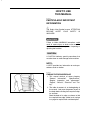
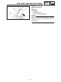
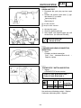
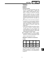
EC082000
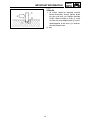
FINDING THE REQUIRED PAGE
1. This manual consists of seven chapters;
“General
Information”,
“Specifications”,
“Regular inspection and adjustments”,
“Engine”, “Chassis”, “Electrical” and “Tuning”.
2. The table of contents is at the beginning of
the manual. Look over the general layout of
the book before finding then required chapter and item.
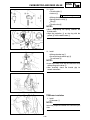
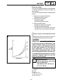
Bend the book at its edge, as shown, to find
the required fore edge symbol mark and go
to a page for required item and description.
EC083000
MANUAL FORMAT
All of the procedures in this manual are organized in a sequential, step-by-step format. The information has been complied to provide the mechanic with an easy to read, handy reference that contains
comprehensive explanations of all disassembly, repair, assembly, and inspection operations.
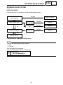
In this revised format, the condition of a faulty component will precede an arrow symbol and the
course of action required will follow the symbol, e.g.,
9Bearings
Pitting/Damage→ Replace.
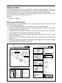
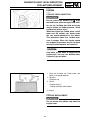
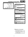
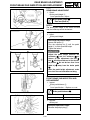
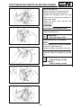
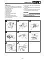
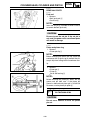
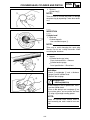
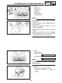
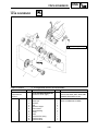
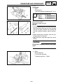
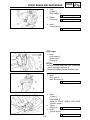
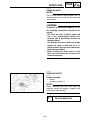
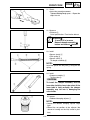
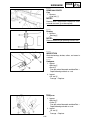
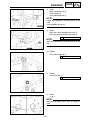
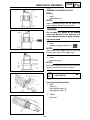
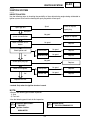
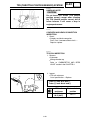
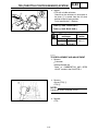
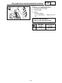
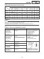
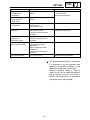
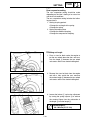
EC084002
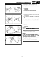
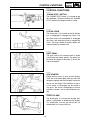
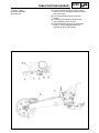
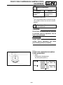
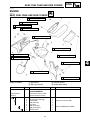
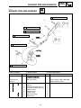
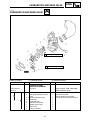
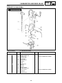
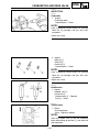
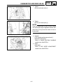
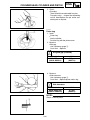
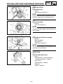
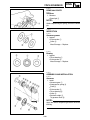
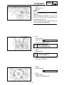
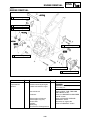
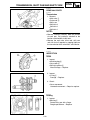
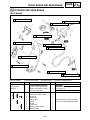
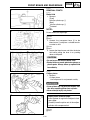
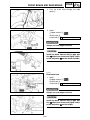
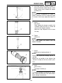
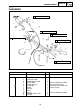
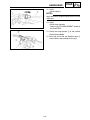
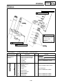
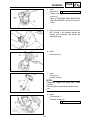
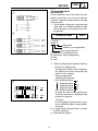
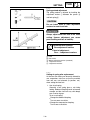
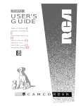
HOW TO READ DESCRIPTIONS
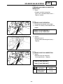
To help identify parts and clarify procedure steps, there are exploded diagrams at the start of each
removal and disassembly section.
1. An easy-to-see exploded diagram 1 is provided for removal and disassembly jobs.
2. Numbers 2 are given in the order of the jobs in the exploded diagram. A number that is enclosed
by a circle indicates a disassembly step.
3. An explanation of jobs and notes is presented in an easy-to-read way by the use of symbol marks
3. The meanings of the symbol marks are given on the next page.
4. A job instruction chart 4 accompanies the exploded diagram, providing the order of jobs, names
of parts, notes in jobs, etc.
5. Extent of removal 5 is provided in the job instruction chart to save the trouble of an unnecessary
removal job.
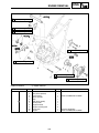
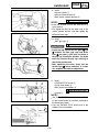
6. For jobs requiring more information, the step-by-step format supplements 6 are given in addition
to the exploded diagram and job instruction chart.
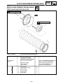
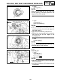
1
CLUTCH AND PR MARY DR VEN GEAR
ENG
O2@@@@@@6K
O2@@@@@@@@@@@@@@6K
O2@@@@@@@@@@@@@@@@@@@@@@6K
?O2@@@@@@@@@@@@@@@@@@@@@@@@@@@6X
O2@@@@@@@@@@@@@@@@@@@@@@@@@@@@@@@)K?
O2@@@@@@@@@@@@@@@@@@@@@@@@@@@@@@@@@@@6K?
O2@@@@@@@@@@@@@@@@@@@@@@@@@@@@@@@@@@@@@@@6X?
O2@@@@@@@@@@@@@@@@@@@@@@@@@@@@@@@@@@@@@@@@@@)K
O2@@@@@@@@@@@@@@@@@@@@@@@@@@@@@@@@@@@@@@@@@@@@@@6X
W2@@@@@@@@@@@@@@@@@@@@@@@@@@@@@@@@@@@@@@@@@@@@@@@@@)X?
?O&@@@@@@@@@@@@@@@@@@@@@@@@@@@@@@@@@@@@@@@@@@@@@@@@@@@)X
?W2@@@@@@@@@@@@@@@@@@@@@@@@@@@@@@@@@@@@@@@@@@@@@@@@@@@@@@)X?
O&@@@@@@@@@@@@@@@@@@@@@@@@@@@@@@@@@@@@@@@@@@@@@@@@@@@@@@@@)X
W2@@@@@@@@@@@@@@@@@@@@@@@@@@@@@@@@@@@@@@@@@@@@@@@@@@@@@@@@@@@1
?O&@@@@@@@@@@@@@@@@@@@@@@@@@@@@@@@@@@@@@@@@@@@@@@@@@@@@@@@@@@@@@L?
?O2@@@@@@@@@@@@@@@@@@@@@@@@@@@@@@@@@@@@@@@@@@@@@@@@@@@@@@@@@@@@@@@1?
?W2@@@@@@@@@@@@@@@@@@@@@@@@@@@@@@@@@@@@@@@@@@@@@@@@@@@@@@@@@@@@@@@@@@L
O&@@@@@@@@@@@@@@@@@@@@@@@@@@@@@@@@@@@@@@@@@@@@@@@@@@@@@@@@@@@@@@@@@@@1
O2@@@@@@@@@@@@@@@@@@@@@@@@@@@@@@@@@@@@@@@@@@@@@@@@@@@@@@@@@@@@@@@@@@@@@@
W2@@@@@@@@@@@@@@@@@@@@@@@@@@@@@@@@@@@@@@@@@@@@@@@@@@@@@@@@@@@@@@@@@@@@@@@@
?W&@@@@@@@@@@@@@@@@@@@@@@@@@@@@@@@@@@@@@@@@@@@@@@@@@@@@@@@@@@@@@@@@@@@@@@@@@
O&@@@@@@@@@@@@@@@@@@@@@@@@@@@@@@@@@@@@@@@@@@@@@@@@@@@@@@@@@@@@@@@@@@@@@@@@@@
W2@@@@@@@@@@@@@@@@@@@@@@@@@@@@@@@@@@@@@@@@@@@@@@@@@@@@@@@@@@@@@@@@@@@@@@@@@@@@
?O&@@@@@@@@@@@@@@@@@@@@@@@@@@@@@@@@@@@@@@@@@@@@@@@@@@@@@@@@@@@@@@@@@@@@@@@@@@@@@
?O2@@@@@@@@@@@@@@@@@@@@@@@@@@@@@@@@@@@@@@@@@@@@@@@@@@@@@@@@@@@@@@@@@@@@@@@@@@@@(M?
?W2@@@@@@@@@@@@@@@@@@@@@@@@@@@@@@@@@@@@@@@@@@@@@@@@@@@@@@@@@@@@@@@@@@@@@@@@@@@@@(Y
O&@@@@@@@@@@@@@@@@@@@@@@@@@@@@@@@@@@@@@@@@@@@@@@@@@@@@@@@@@@@@@@@@@@@@@@@@@@@@@0Y?
W2@@@@@@@@@@@@@@@@@@@@@@@@@@@@@@@@@@@@@@@@@@@@@@@@@@@@@@@@@@@@@@@@@@@@@@@@@@@@@(M?
?O&@@@@@@@@@@@@@@@@@@@@@@@@@@@@@@@@@@@@@@@@@@@@@@@@@@@@@@@@@@@@@@@@@@@@@@@@@@@@@0Y
?O2@@@@@@@@@@@@@@@@@@@@@@@@@@@@@@@@@@@@@@@@@@@@@@@@@@@@@@@@@@@@@@@@@@@@@@@@@@@@@(M
?O2@@@@@@@@@@@@@@@@@@@@@@@@@@@@@@@@@@@@@@@@@@@@@@@@@@@@@@@@@@@@@@@@@@@@@@@@@@@@@@0Y?
?W2@@@@@@@@@@@@@@@@@@@@@@@@@@@@@@@@@@@@@@@@@@@@@@@@@@@@@@@@@@@@@@@@@@@@@@@@@@@@@@(M?
O&@@@@@@@@@@@@@@@@@@@@@@@@@@@@@@@@@@@@@@@@@@@@@@@@@@@@@@@@@@@@@@@@@@@@@@@@@@@@@@0Y
W2@@@@@@@@@@@@@@@@@@@@@@@@@@@@@@@@@@@@@@@@@@@@@@@@@@@@@@@@@@@@@@@@@@@@@@@@@@@@@@0M
?O&@@@@@@@@@@@@@@@@@@@@@@@@@@@@@@@@@@@@@@@@@@@@@@@@@@@@@@@@@@@@@@@@@@@@@@@@@@@@@(M
?W2@@@@@@@@@@@@@@@@@@@@@@@@@@@@@@@@@@@@@@@@@@@@@@@@@@@@@@@@@@@@@@@@@@@@@@@@@@@@@@0Y?
O&@@@@@@@@@@@@@@@@@@@@@@@@@@@@@@@@@@@@@@@@@@@@@@@@@@@@@@@@@@@@@@@@@@@@@@@@@@@@@(M?
O2@@@@@@@@@@@@@@@@@@@@@@@@@@@@@@@@@@@@@@@@@@@@@@@@@@@@@@@@@@@@@@@@@@@@@@@@@@@@@@0Y
W2@@@@@@@@@@@@@@@@@@@@@@@@@@@@@@@@@@@@@@@@@@@@@@@@@@@@@@@@@@@@@@@@@@@@@@@@@@@@@@(M
?O&@@@@@@@@@@@@@@@@@@@@@@@@@@@@@@@@@@@@@@@@@@@@@@@@@@@@@@@@@@@@@@@@@@@@@@@@@@@@@@0Y?
?O2@@@@@@@@@@@@@@@@@@@@@@@@@@@@@@@@@@@@@@@@@@@@@@@@@@@@@@@@@@@@@@@@@@@@@@@@@@@@@@(M?
?O2@@@@@@@@@@@@@@@@@@@@@@@@@@@@@@@@@@@@@@@@@@@@@@@@@@@@@@@@@@@@@@@@@@@@@@@@@@@@@@@0Y
?W2@@@@@@@@@@@@@@@@@@@@@@@@@@@@@@@@@@@@@@@@@@@@@@@@@@@@@@@@@@@@@@@@@@@@@@@@@@@@@@@(M
O&@@@@@@@@@@@@@@@@@@@@@@@@@@@@@@@@@@@@@@@@@@@@@@@@@@@@@@@@@@@@@@@@@@@@@@@@@@@@@@@0Y?
W2@@@@@@@@@@@@@@@@@@@@@@@@@@@@@@@@@@@@@@@@@@@@@@@@@@@@@@@@@@@@@@@@@@@@@@@@@@@@@@@(M?
?O&@@@@@@@@@@@@@@@@@@@@@@@@@@@@@@@@@@@@@@@@@@@@@@@@@@@@@@@@@@@@@@@@@@@@@@@@@@@@@@@0Y
?W2@@@@@@@@@@@@@@@@@@@@@@@@@@@@@@@@@@@@@@@@@@@@@@@@@@@@@@@@@@@@@@@@@@@@@@@@@@@@@@@(M
O&@@@@@@@@@@@@@@@@@@@@@@@@@@@@@@@@@@@@@@@@@@@@@@@@@@@@@@@@@@@@@@@@@@@@@@@@@@@@@@@0Y?
W2@@@@@@@@@@@@@@@@@@@@@@@@@@@@@@@@@@@@@@@@@@@@@@@@@@@@@@@@@@@@@@@@@@@@@@@@@@@@@@@(M?
?O2@@?
?O&@@@@@@@@@@@@@@@@@@@@@@@@@@@@@@@@@@@@@@@@@@@@@@@@@@@@@@@@@@@@@@@@@@@@@@@@@@@@@@@0Y
?W2@@@@L
?O2@@@@@@@@@@@@@@@@@@@@@@@@@@@@@@@@@@@@@@@@@@@@@@@@@@@@@@@@@@@@@@@@@@@@@@@@@@@@@@@(M
O&@@@@@)X?
?O2@@@@@@@@@@@@@@@@@@@@@@@@@@@@@@@@@@@@@@@@@@@@@@@@@@@@@@@@@@@@@@@@@@@@@@@@@@@@@@@@0Y?
W2@@@@@@@@1?
?W2@@@@@@@@@@@@@@@@@@@@@@@@@@@@@@@@@@@@@@@@@@@@@@@@@@@@@@@@@@@@@@@@@@@@@@@@@@@@@@@@0M?
?W&@@@@@@@@@@L
O&@@@@@@@@@@@@@@@@@@@@@@@@@@@@@@@@@@@@@@@@@@@@@@@@@@@@@@@@@@@@@@@@@@@@@@@@@@@@@@@(M?
O&@@@@@@@@@@@1
W2@@@@@@@@@@@@@@@@@@@@@@@@@@@@@@@@@@@@@@@@@@@@@@@@@@@@@@@@@@@@@@@@@@@@@@@@@@@@@@@@0Y
O2@@@@@@@@@@@@@@
?O&@@@@@@@@@@@@@@@@@@@@@@@@@@@@@@@@@@@@@@@@@@@@@@@@@@@@@@@@@@@@@@@@@@@@@@@@@@@@@@@(M
W2@@@@@@@@@@@@@@@@
?O2@@@@@@@@@@@@@@@@@@@@@@@@@@@@@@@@@@@@@@@@@@@@@@@@@@@@@@@@@@@@@@@@@@@@@@@@@@@@@@@@0Y?
?O&@@@@@@@@@@@@@@@@5
?W2@@@@@@@@@@@@@@@@@@@@@@@@@@@@@@@@@@@@@@@@@@@@@@@@@@@@@@@@@@@@@@@@@@@@@@@@@@@@@@@@(M?
?W2@@@@@@@@@@@@@@@@@0Y
O&@@@@@@@@@@@@@@@@@@@@@@@@@@@@@@@@@@@@@@@@@@@@@@@@@@@@@@@@@@@@@@@@@@@@@@@@@@@@@@@@0Y
O&@@@@@@@@@@@@@@@@(M
W2@@@@@@@@@@@@@@@@@@@@@@@@@@@@@@@@@@@@@@@@@@@@@@@@@@@@@@@@@@@@@@@@@@@@@@@@@@@@@@@@(M
W2@@@@@@@@@@@@@@@@@0Y?
?O&@@@@@@@@@@@@@@@@@@@@@@@@@@@@@@@@@@@@@@@@@@@@@@@@@@@@@@@@@@@@@@@@@@@@@@@@@@@@@@@@0Y?
?O&@@@@@@@@@@@@@@@@(M?
?W2@@@@@@@@@@@@@@@@@@@@@@@@@@@@@@@@@@@@@@@@@@@@@@@@@@@@@@@@@@@@@@@@@@@@@@@@@@@@@@@@(M?
?W2@@@@@@@@@@@@@@@@@0Y
O&@@@@@@@@@@@@@@@@@@@@@@@@@@@@@@@@@@@@@@@@@@@@@@@@@@@@@@@@@@@@@@@@@@@@@@@@@@@@@@@@0Y
O&@@@@@@@@@@@@@@@@(M
O2@@@@@@@@@@@@@@@@@@@@@@@@@@@@@@@@@@@@@@@@@@@@@@@@@@@@@@@@@@@@@@@@@@@@@@@@@@@@@@@@(M
W2@@@@@@@@@@@@@@@@@0Y?
W2@@@@@@@@@@@@@@@@@@@@@@@@@@@@@@@@@@@@@@@@@@@@@@@@@@@@@@@@@@@@@@@@@@@@@@@@@@@@@@@@@0Y?
?O&@@@@@@@@@@@@@@@@(M?
?O&@@@@@@@@@@@@@@@@@@@@@@@@@@@@@@@@@@@@@@@@@@@@@@@@@@@@@@@@@@@@@@@@@@@@@@@@@@@@@@@@(M?
?W2@@@@@@@@@@@@@@@@@0Y
?W2@@@@@@@@@@@@@@@@@@@@@@@@@@@@@@@@@@@@@@@@@@@@@@@@@@@@@@@@@@@@@@@@@@@@@@@@@@@@@@@@@0Y
O&@@@@@@@@@@@@@@@@(M
O&@@@@@@@@@@@@@@@@@@@@@@@@@@@@@@@@@@@@@@@@@@@@@@@@@@@@@@@@@@@@@@@@@@@@@@@@@@@@@@@@(M
O2@@@@@@@@@@@@@@@@@0Y?
?O2@6X
O2@@@@@@@@@@@@@@@@@@@@@@@@@@@@@@@@@@@@@@@@@@@@@@@@@@@@@@@@@@@@@@@@@@@@@@@@@@@@@@@@@0Y?
W2@@@@@@@@@@@@@@@@@(M?
?W2@@@@1
W2@@@@@@@@@@@@@@@@@@@@@@@@@@@@@@@@@@@@@@@@@@@@@@@@@@@@@@@@@@@@@@@@@@@@@@@@@@@@@@@@@(M?
?W&@@@@@@@@@@@@@@@@@0Y
O&@@@@@@L?
?O&@@@@@@@@@@@@@@@@@@@@@@@@@@@@@@@@@@@@@@@@@@@@@@@@@@@@@@@@@@@@@@@@@@@@@@@@@@@@@@@@@0Y
O&@@@@@@@@@@@@@@@@(M
W2@@@@@@@@)X
?W2@@@@@@@@@@@@@@@@@@@@@@@@@@@@@@@@@@@@@@@@@@@@@@@@@@@@@@@@@@@@@@@@@@@@@@@@@@@@@@@@@0M
W2@@@@@@@@@@@@@@@@@0Y?
?O&@@@@@@@@@@1
O&@@@@@@@@@@@@@@@@@@@@@@@@@@@@@@@@@@@@@@@@@@@@@@@@@@@@@@@@@@@@@@@@@@@@@@@@@@@@@@@@(M
?W&@@@@@@@@@@@@@@@@(M?
?W2@@@@@@@@@@@@@L?
W2@@@@@@@@@@@@@@@@@@@@@@@@@@@@@@@@@@@@@@@@@@@@@@@@@@@@@@@@@@@@@@@@@@@@@@@@@@@@@@@@@0Y?
O&@@@@@@@@@@@@@@@@0Y
O&@@@@@@@@@@@@@@1?
?O&@@@@@@@@@@@@@@@@@@@@@@@@@@@@@@@@@@@@@@@@@@@@@@@@@@@@@@@@@@@@@@@@@@@@@@@@@@@@@@@@(M?
O2@@@@@@@@@@@@@@@@0M
W2@@@@@@@@@@@@@@@@@?
?O2@@@@@@@@@@@@@@@@@@@@@@@@@@@@@@@@@@@@@@@@@@@@@@@@@@@@@@@@@@@@@@@@@@@@@@@@@@@@@@@@@0Y
W2@@@@@@@@@@@@@@@@(M
?O&@@@@@@@@@@@@@@@@@5?
?W2@@@@@@@@@@@@@@@@@@@@@@@@@@@@@@@@@@@@@@@@@@@@@@@@@@@@@@@@@@@@@@@@@@@@@@@@@@@@@@@@@(M
?O&@@@@@@@@@@@@@@@@0Y?
?W2@@@@@@@@@@@@@@@@@@0Y?
O&@@@@@@@@@@@@@@@@@@@@@@@@@@@@@@@@@@@@@@@@@@@@@@@@@@@@@@@@@@@@@@@@@@@@@@@@@@@@@@@@@0Y?
?W2@@@@@@@@@@@@@@@@(M?
O&@@@@@@@@@@@@@@@@@(M?
W2@@@@@@@@@@@@@@@@@@@@@@@@@@@@@@@@@@@@@@@@@@@@@@@@@@@@@@@@@@@@@@@@@@@@@@@@@@@@@@@@@(M?
O&@@@@@@@@@@@@@@@@0Y
W2@@@@@@@@@@@@@@@@@@0Y
?O&@@@@@@@@@@@@@@@@@@@@@@@@@@@@@@@@@@@@@@@@@@@@@@@@@@@@@@@@@@@@@@@@@@@@@@@@@@@@@@@@@0Y
W2@@@@@@@@@@@@@@@@(M
?O&@@@@@@@@@@@@@@@@@(M
?O2@@@@@@@@@@@@@@@@@@@@@@@@@@@@@@@@@@@@@@@@@@@@@@@@@@@@@@@@@@@@@@@@@@@@@@@@@@@@@@@@@(M
?W&@@@@@@@@@@@@@@@@0Y?
?W2@@@@@@@@@@@@@@@@@@0Y?
?W2@@@@@@@@@@@@@@@@@@@@@@@@@@@@@@@@@@@@@@@@@@@@@@@@@@@@@@@@@@@@@@@@@@@@@@@@@@@@@@@@@@0Y?
O&@@@@@@@@@@@@@@@(M?
O&@@@@@@@@@@@@@@@@@(M?
W&@@@@@@@@@@@@@@@@@@@@@@@@@@@@@@@@@@@@@@@@@@@@@@@@@@@@@@@@@@@@@@@@@@@@@@@@@@@@@@@@@(M?
O2@@@@@@@@@@@@@@@@0Y
W2@@@@@@@@@@@@@@@@@@0Y
?W&@@@@@@@@@@@@@@@@@@@@@@@@@@@@@@@@@@@@@@@@@@@@@@@@@@@@@@@@@@@@@@@@@@@@@@@@@@@@@@@@@0Y
O2@@@@@@@@@@@@@@@@(M
?O&@@@@@@@@@@@@@@@@@(M
?W-X
W&@@@@@@@@@@@@@@@@@@@@@@@@@@@@@@@@@@@@@@@@@@@@@@@@@@@@@@@@@@@@@@@@@@@@@@@@@@@@@@@@(M
W2@@@@@@@@@@@@@@@@@0Y?
?W2@@@@@@@@@@@@@@@@@@0Y?
W&@)X?
?W&@@@@@@@@@@@@@@@@@@@@@@@@@@@@@@@@@@@@@@@@@@@@@@@@@@@@@@@@@@@@@@@@@@@@@@@@@@@@@@@@0Y?
?O&@@@@@@@@@@@@@@@@(M?
O&@@@@@@@@@@@@@@@@@(M?
?O&@@@1?
W&@@@@@@@@@@@@@@@@@@@@@@@@@@@@@@@@@@@@@@@@@@@@@@@@@@@@@@@@@@@@@@@@@@@@@@@@@@@@@@@(M?
?W2@@@@@@@@@@@@@@@@@0Y
W2@@@@@@@@@@@@@@@@@@0Y
?O2@@@@@@L
?W&@@@@@@@@@@@@@@@@@@@@@@@@@@@@@@@@@@@@@@@@@@@@@@@@@@@@@@@@@@@@@@@@@@@@@@@@@@@@@@@0Y
O&@@@@@@@@@@@@@@@@(M
?O&@@@@@@@@@@@@@@@@@(M
?O2@@@@@@@@1
W&@@@@@@@@@@@@@@@@@@@@@@@@@@@@@@@@@@@@@@@@@@@@@@@@@@@@@@@@@@@@@@@@@@@@@@@@@@@@@@0M
W2@@@@@@@@@@@@@@@@@0Y?
?W2@@@@@@@@@@@@@@@@@@0Y?hf?W2@@@@@@@@@@@L?
7@@@@@@@@@@@@@@@@@@@@@@@@@@@@@@@@@@@@@@@@@@@@@@@@@@@@@@@@@@@@@@@@@@@@@@@@@@@@@(M
?O&@@@@@@@@@@@@@@@@(M?
O&@@@@@@@@@@@@@@@@@(M?
W&@@@@@@@@@@@@)X
?J@@@@@@@@@@@@@@@@@@@@@@@@@@@@@@@@@@@@@@@@@@@@@@@@@@@@@@@@@@@@@@@@@@@@@@@@@@@@@0Y?
?W2@@@@@@@@@@@@@@@@@0Y
W2@@@@@@@@@@@@@@@@@@0Y
?O&@@@@@@@@@@@@@@1
W&@@@@@@@@@@@@@@@@@@@@@@@@@@@@@@@@@@@@@@@@@@@@@@@@@@@@@@@@@@@@@@@@@@@@@@@@@@@(M?
O&@@@@@@@@@@@@@@@@(M
?O&@@@@@@@@@@@@@@@@@(M
?W2@@@@@@@@@@@@@@@@@
7@@@@@@@@@@@@@@@@@@@@@@@@@@@@@@@@@@@@@@@@@@@@@@@@@@@@@@@@@@@@@@@@@@@@@@@@@@@0Y
O2@@@@@@@@@@@@@@@@@0Y?
?W2@@@@@@@@@@@@@@@@@@0Y?
O&@@@@@@@@@@@@@@@@@5
@@@@@@@@@@@@@@@@@@@@@@@@@@@@@@@@@@@@@@@@@@@@@@@@@@@@@@@@@@@@@@@@@@@@@@@@@@(M
W2@@@@@@@@@@@@@@@@@(M?
O&@@@@@@@@@@@@@@@@@(M?
W2@@@@@@@@@@@@@@@@@@0Y
?J@@@@@@@@@@@@@@@@@@@@@@@@@@@@@@@@@@@@@@@@@@@@@@@@@@@@@@@@@@@@@@@@@@@@@@@@@0Y?
?O&@@@@@@@@@@@@@@@@@0Y
W2@@@@@@@@@@@@@@@@@@0Y
?O&@@@@@@@@@@@@@@@@@(M
?7@@@@@@@@@@@@@@@@@@@@@@@@@@@@@@@@@@@@@@@@@@@@@@@@@@@@@@@@@@@@@@@@@@@@@@@(M?
?W2@@@@@@@@@@@@@@@@@(M
?O&@@@@@@@@@@@@@@@@@(M
?O2@@@@@@@@@@@@@@@@@@0Y?
J@@@@@@@@@@@@@@@@@@@@@@@@@@@@@@@@@@@@@@@@@@@@@@@@@@@@@@@@@@@@@@@@@@@@@@@0Y
O&@@@@@@@@@@@@@@@@@0Y?
?W2@@@@@@@@@@@@@@@@@@0Y?hf?W2@@@@@@@@@@@@@@@@@@(M?
7@@@@@@@@@@@@@@@@@@@@@@@@@@@@@@@@@@@@@@@@@@@@@@@@@@@@@@@@@@@@@@@@@@@@@(M
W2@@@@@@@@@@@@@@@@@(M?
O&@@@@@@@@@@@@@@@@@(M?
O&@@@@@@@@@@@@@@@@@@0Y
@@@@@@@@@@@@@@@@@@@@@@@@@@@@@@@@@@@@@@@@@@@@@@@@@@@@@@@@@@@@@@@@@@@@@0Y?
?W&@@@@@@@@@@@@@@@@@0Y
W2@@@@@@@@@@@@@@@@@@0Y
W2@@@@@@@@@@@@@@@@@@(M
@@@@@@@@@@@@@@@@@@@@@@@@@@@@@@@@@@@@@@@@@@@@@@@@@@@@@@@@@@@@@@@@@@@(M?
O&@@@@@@@@@@@@@@@@(M
?O&@@@@@@@@@@@@@@@@@(M
?O&@@@@@@@@@@@@@@@@@@0Y?
?J@@@@@@@@@@@@@@@@@@@@@@@@@@@@@@@@@@@@@@@@@@@@@@@@@@@@@@@@@@@@@@@@@@0Y
W2@@@@@@@@@@@@@@@@@0Y?
?W2@@@@@@@@@@@@@@@@@@0Y?hf?W2@@@@@@@@@@@@@@@@@@(M?
?7@@@@@@@@@@@@@@@@@@@@@@@@@@@@@@@@@@@@@@@@@@@@@@@@@@@@@@@@@@@@@@@@(M
?O&@@@@@@@@@@@@@@@@0M?
O&@@@@@@@@@@@@@@@@@(M?
W&@@@@@@@@@@@@@@@@@@0Y
?@@@@@@@@@@@@@@@@@@@@@@@@@@@@@@@@@@@@@@@@@@@@@@@@@@@@@@@@@@@@@@@@0Y?
?O2@@@@@@@@@@@@@@@@(M?
W2@@@@@@@@@@@@@@@@@@0Y
?O&@@@@@@@@@@@@@@@@@(M
?@@@@@@@@@@@@@@@@@@@@@@@@@@@@@@@@@@@@@@@@@@@@@@@@@@@@@@@@@@@@@@(M?
?W2@@@@@@@@@@@@@@@@@0Y
?O&@@@@@@@@@@@@@@@@@(M
?O2@@@@@@@@@@@@@@@@@@0Y?
J@@@@@@@@@@@@@@@@@@@@@@@@@@@@@@@@@@@@@@@@@@@@@@@@@@@@@@@@@@@@@0Y
O&@@@@@@@@@@@@@@@@(M
?W2@@@@@@@@@@@@@@@@@@0Y?hf?W2@@@@@@@@@@@@@@@@@@(M?
?O26X?
7@@@@@@@@@@@@@@@@@@@@@@@@@@@@@@@@@@@@@@@@@@@@@@@@@@@@@@@@@@@(M
W2@@@@@@@@@@@@@@@@@0Y?
O&@@@@@@@@@@@@@@@@@(M?
O&@@@@@@@@@@@@@@@@@@0Y
?W2@@@)X
@@@@@@@@@@@@@@@@@@@@@@@@@@@@@@@@@@@@@@@@@@@@@@@@@@@@@@@@@@@0Y?
?O&@@@@@@@@@@@@@@@@(M?
W2@@@@@@@@@@@@@@@@@@0Y
W2@@@@@@@@@@@@@@@@@@(M
O&@@@@@)X?
@@@@@@@@@@@@@@@@@@@@@@@@@@@@@@@@@@@@@@@@@@@@@@@@@@@@@@@@@0M?
?W2@@@@@@@@@@@@@@@@@0Y
?O&@@@@@@@@@@@@@@@@@(M
?O&@@@@@@@@@@@@@@@@@@0Y?
W2@@@@@@@@1?
@@@@@@@@@@@@@@@@@@@@@@@@@@@@@@@@@@@@@@@@@@@@@@@@@@@@@@@(M?
O&@@@@@@@@@@@@@@@@(M
?W2@@@@@@@@@@@@@@@@@@0Y?hf?W2@@@@@@@@@@@@@@@@@@(M?
?O&@@@@@@@@@@L
@@@@@@@@@@@@@@@@@@@@@@@@@@@@@@@@@@@@@@@@@@@@@@@@@@@@@@0Y
W2@@@@@@@@@@@@@@@@@0Y?
O&@@@@@@@@@@@@@@@@@(M?
W&@@@@@@@@@@@@@@@@@@(Y
?W2@@@@@@@@@@@@1
@@@@@@@@@@@@@@@@@@@@@@@@@@@@@@@@@@@@@@@@@@@@@@@@@@@@(M
?O&@@@@@@@@@@@@@@@@(M?
W2@@@@@@@@@@@@@@@@@@0Y
?O&@@@@@@@@@@@@@@@@@@0Y?
O&@@@@@@@@@@@@@@
@@@@@@@@@@@@@@@@@@@@@@@@@@@@@@@@@@@@@@@@@@@@@@@@@@@0Y?
?W2@@@@@@@@@@@@@@@@@0Y
?O&@@@@@@@@@@@@@@@@@(M
?W2@@@@@@@@@@@@@@@@@@(M?
W2@@@@@@@@@@@@@@@@
@@@@@@@@@@@@@@@@@@@@@@@@@@@@@@@@@@@@@@@@@@@@@@@@@(M?
O&@@@@@@@@@@@@@@@@(M
?O2@@@@@@@@@@@@@@@@@@0Y?
O&@@@@@@@@@@@@@@@@@@0Y
?O&@@@@@@@@@@@@@@@@5
@@@@@@@@@@@@@@@@@@@@@@@@@@@@@@@@@@@@@@@@@@@@@@@@0Y
W2@@@@@@@@@@@@@@@@@0Y?
?W2@@@@@@@@@@@@@@@@@@(M?
W2@@@@@@@@@@@@@@@@@@0M
?W2@@@@@@@@@@@@@@@@@0Y
@@@@@@@@@@@@@@@@@@@@@@@@@@@@@@@@@@@@@@@@@@@@@@(M
?O&@@@@@@@@@@@@@@@@(M?
O&@@@@@@@@@@@@@@@@@@0Y
?O&@@@@@@@@@@@@@@@@@(M
O&@@@@@@@@@@@@@@@@(M
3@@@@@@@@@@@@@@@@@@@@@@@@@@@@@@@@@@@@@@@@@@@@0Y?
?W2@@@@@@@@@@@@@@@@@0Y
W2@@@@@@@@@@@@@@@@@@(M
?O2@@@@@@@@@@@@@@@@@@0Y?
W2@@@@@@@@@@@@@@@@@0Y?
N@@@@@@@@@@@@@@@@@@@@@@@@@@@@@@@@@@@@@@@@@@(M?
O&@@@@@@@@@@@@@@@@(M
?O&@@@@@@@@@@@@@@@@@@0Y?hf?W2@@@@@@@@@@@@@@@@@@(M?
?O&@@@@@@@@@@@@@@@@(M?
?@@@@@@@@@@@@@@@@@@@@@@@@@@@@@@@@@@@@@@@@@0Y
W2@@@@@@@@@@@@@@@@@0Y?
?W2@@@@@@@@@@@@@@@@@@(M?
O&@@@@@@@@@@@@@@@@@@0Y
?W2@@@@@@@@@@@@@@@@@0Y
?@@@@@@@@@@@@@@@@@@@@@@@@@@@@@@@@@@@@@@@(M
?O&@@@@@@@@@@@@@@@@(M?
O&@@@@@@@@@@@@@@@@@@0Y
W2@@@@@@@@@@@@@@@@@@(M
O&@@@@@@@@@@@@@@@@(M
?3@@@@@@@@@@@@@@@@@@@@@@@@@@@@@@@@@@@@@0Y?
?W2@@@@@@@@@@@@@@@@@0Y
W2@@@@@@@@@@@@@@@@@@(M
?O&@@@@@@@@@@@@@@@@@@0Y?
W2@@@@@@@@@@@@@@@@@0Y?
?N@@@@@@@@@@@@@@@@@@@@@@@@@@@@@@@@@@@0M?
O&@@@@@@@@@@@@@@@@(M
?O&@@@@@@@@@@@@@@@@@@0Y?hf?O2@@@@@@@@@@@@@@@@@@0M?
?O&@@@@@@@@@@@@@@@@(M?
@@@@@@@@@@@@@@@@@@@@@@@@@@@@@@@@@(M?
W2@@@@@@@@@@@@@@@@@0Y?
?W2@@@@@@@@@@@@@@@@@@0M?hf?W2@@@@@@@@@@@@@@@@@@(M?
?W2@@@@@@@@@@@@@@@@@0Y
@@@@@@@@@@@@@@@@@@@@@@@@@@@@@@@@0Y
?O&@@@@@@@@@@@@@@@@(M?
O&@@@@@@@@@@@@@@@@@(M?
O&@@@@@@@@@@@@@@@@@@(Y
O&@@@@@@@@@@@@@@@@(M
O2@6X?
3@@@@@@@@@@@@@@@@@@@@@@@@@@@@@(M
?W2@@@@@@@@@@@@@@@@@0Y
W2@@@@@@@@@@@@@@@@@@0Y
W2@@@@@@@@@@@@@@@@@@@0Y?
W2@@@@@@@@@@@@@@@@@0Y?
W2@@@@)X
N@@@@@@@@@@@@@@@@@@@@@@@@@@@@(Y?
O&@@@@@@@@@@@@@@@@(M
?O&@@@@@@@@@@@@@@@@@(M
?O&@@@@@@@@@@@@@@@@@@(M?
?O&@@@@@@@@@@@@@@@@(M?
?O&@@@@@@1
?3@@@@@@@@@@@@@@@@@@@@@@@@@@0Y
W2@@@@@@@@@@@@@@@@@0Y?
?W2@@@@@@@@@@@@@@@@@@0Y?hf?O2@@@@@@@@@@@@@@@@@@@(Y
?O2@@@@@@@@@@@@@@@@@0Y
?W2@@@@@@@@@L?
?N@@@@@@@@@@@@@@@@@@@@@@@@0M
?O&@@@@@@@@@@@@@@@@(M?
O&@@@@@@@@@@@@@@@@@(M?hf?W2@@@@@@@@@@@@@@@@@@@@0Y?
?W2@@@@@@@@@@@@@@@@@(M
O&@@@@@@@@@@)X
3@@@@@@@@@@@@@@@@@@@@@(M
?W2@@@@@@@@@@@@@@@@@0Y
W2@@@@@@@@@@@@@@@@@@0Y
W&@@@@@@@@@@@@@@@@@@@0M?
O&@@@@@@@@@@@@@@@@@0Y?
W2@@@@@@@@@@@@@1
V'@@@@@@@@@@@@@@@@@@@0Y?
O&@@@@@@@@@@@@@@@@(M
?O&@@@@@@@@@@@@@@@@@(M
?O&@@@@@@@@@@@@@@@@@@(M?
W2@@@@@@@@@@@@@@@@@(M?
?O&@@@@@@@@@@@@@@@
?N@@@@@@@@@@@@@@@@@0M?
W2@@@@@@@@@@@@@@@@@0Y?
?W2@@@@@@@@@@@@@@@@@@0Y?hf?W2@@@@@@@@@@@@@@@@@@@0Y
?O&@@@@@@@@@@@@@@@@@(Y
?W2@@@@@@@@@@@@@@@@@
3@@@@@@@@@@@@@@0M?
?O&@@@@@@@@@@@@@@@@0M?
O&@@@@@@@@@@@@@@@@@(M?
O&@@@@@@@@@@@@@@@@@@0M
?W2@@@@@@@@@@@@@@@@@@0Y?
O&@@@@@@@@@@@@@@@@@5
V'@@@@@@@@@@@(M?
?W2@@@@@@@@@@@@@@@@(M?
W2@@@@@@@@@@@@@@@@@@0Y
W2@@@@@@@@@@@@@@@@@@(M
O&@@@@@@@@@@@@@@@@@0M?
W2@@@@@@@@@@@@@@@@@@0Y
?V'@@@@@@@@@0Y
O&@@@@@@@@@@@@@@@@0Y
?O&@@@@@@@@@@@@@@@@@(M
?O&@@@@@@@@@@@@@@@@@@0Y?
W2@@@@@@@@@@@@@@@@@(M?
?O&@@@@@@@@@@@@@@@@@(M
V'@@@@@@(M
W2@@@@@@@@@@@@@@@@(M
?W2@@@@@@@@@@@@@@@@@@0Y?hf?W2@@@@@@@@@@@@@@@@@@(M?
?O&@@@@@@@@@@@@@@@@@0Y
?W2@@@@@@@@@@@@@@@@@@0Y?
?V4@@@@0Y?
?O&@@@@@@@@@@@@@@@@0Y?
O&@@@@@@@@@@@@@@@@@(M?
O&@@@@@@@@@@@@@@@@@@0Y
?W2@@@@@@@@@@@@@@@@@0M
O&@@@@@@@@@@@@@@@@@(M?
?I40M?
?W2@@@@@@@@@@@@@@@@(M?
W2@@@@@@@@@@@@@@@@@@0Y
O2@@@@@@@@@@@@@@@@@@(M
O&@@@@@@@@@@@@@@@@(M
O2@@@@@@@@@@@@@@@@@@0Y
O&@@@@@@@@@@@@@@@@0Y
?O&@@@@@@@@@@@@@@@@@(M
W2@@@@@@@@@@@@@@@@@@@0Y?
W2@@@@@@@@@@@@@@@@@(Y?
W2@@@@@@@@@@@@@@@@@@(M
W2@@@@@@@@@@@@@@@@(M
?W2@@@@@@@@@@@@@@@@@@0Y?hf?O&@@@@@@@@@@@@@@@@@@0M?
?O&@@@@@@@@@@@@@@@@@0Y
?O&@@@@@@@@@@@@@@@@@@0Y?he?O@K
7@@@@@@@@@@@@@@@@0Y?
O&@@@@@@@@@@@@@@@@@(M?hf?W2@@@@@@@@@@@@@@@@@@(M?
?W2@@@@@@@@@@@@@@@@@(M
?W2@@@@@@@@@@@@@@@@@@(M?he?W2@@@@?
@@@@@@@@@@@@@@@(M?
W2@@@@@@@@@@@@@@@@@@0Y
O&@@@@@@@@@@@@@@@@@@0Y
O&@@@@@@@@@@@@@@@@@0Y?
O&@@@@@@@@@@@@@@@@@@0YhfO&@@@@@L
3@@@@@@@@@@@@@0Y
?O&@@@@@@@@@@@@@@@@@(M
O2@@@@@@@@@@@@@@@@@@(M
W2@@@@@@@@@@@@@@@@@0M?
W2@@@@@@@@@@@@@@@@@@(MhfW2@@@@@@@)X?
V'@@@@@@@@@@(M
?W2@@@@@@@@@@@@@@@@@@0Y?hfW2@@@@@@@@@@@@@@@@@@@0Y?
?O&@@@@@@@@@@@@@@@@(M?
?O&@@@@@@@@@@@@@@@@@@0Y?he?O&@@@@@@@@@1?
?V'@@@@@@@@0Y?
O&@@@@@@@@@@@@@@@@@(M?hf?O&@@@@@@@@@@@@@@@@@@(M?
?W2@@@@@@@@@@@@@@@@@0Y
?W2@@@@@@@@@@@@@@@@@@0M?he?W2@@@@@@@@@@@@L
V'@@@@@(M?
W2@@@@@@@@@@@@@@@@@@0Yhf?O2@@@@@@@@@@@@@@@@@@@0Y
O&@@@@@@@@@@@@@@@@(M
O&@@@@@@@@@@@@@@@@@(M?hfO&@@@@@@@@@@@@@1
?V'@@@0Y
?O&@@@@@@@@@@@@@@@@@(Mhf?W2@@@@@@@@@@@@@@@@@@@(M
W2@@@@@@@@@@@@@@@@@0Y?
W2@@@@@@@@@@@@@@@@@@0YhfO2@@@@@@@@@@@@@@@@
V40M
?W2@@@@@@@@@@@@@@@@@@0Y?hfW&@@@@@@@@@@@@@@@@@@@0Y?
?O&@@@@@@@@@@@@@@@@(M?
?O&@@@@@@@@@@@@@@@@@(MhfW2@@@@@@@@@@@@@@@@@@
O&@@@@@@@@@@@@@@@@@(M?hf?O&@@@@@@@@@@@@@@@@@@(M?
?W2@@@@@@@@@@@@@@@@@0Y
?W2@@@@@@@@@@@@@@@@@@0Y?he?O&@@@@@@@@@@@@@@@@@@5
O2@@@@@@@@@@@@@@@@@@0Yhf?W2@@@@@@@@@@@@@@@@@@@0Y
O&@@@@@@@@@@@@@@@@(M
O&@@@@@@@@@@@@@@@@@(M?he?W2@@@@@@@@@@@@@@@@@@@0Y
W2@@@@@@@@@@@@@@@@@@(M
W&@@@@@@@@@@@@@@@@@@(M
W2@@@@@@@@@@@@@@@@@0Y?
W2@@@@@@@@@@@@@@@@@@0YhfO&@@@@@@@@@@@@@@@@@@(M
?O&@@@@@@@@@@@@@@@@@@0Y?hf?O&@@@@@@@@@@@@@@@@@@0Y?
?O&@@@@@@@@@@@@@@@@(M?
?O&@@@@@@@@@@@@@@@@@(MhfW2@@@@@@@@@@@@@@@@@@@0Y?
?W2@@@@@@@@@@@@@@@@@@(M?hf?O2@@@@@@@@@@@@@@@@@@(M?
?W2@@@@@@@@@@@@@@@@@0Y
?W2@@@@@@@@@@@@@@@@@@0Y?he?O&@@@@@@@@@@@@@@@@@@(M?
W&@@@@@@@@@@@@@@@@@@0Yhf?W2@@@@@@@@@@@@@@@@@@@0Y
O&@@@@@@@@@@@@@@@@(M
O&@@@@@@@@@@@@@@@@@(M?he?W2@@@@@@@@@@@@@@@@@@@0Y
?O&@@@@@@@@@@@@@@@@@(M
O&@@@@@@@@@@@@@@@@@@(M
W2@@@@@@@@@@@@@@@@@0Y?
W2@@@@@@@@@@@@@@@@@@0YhfO&@@@@@@@@@@@@@@@@@@(M
?W2@@@@@@@@@@@@@@@@@@0Y?hfW2@@@@@@@@@@@@@@@@@@@0Y?
?O&@@@@@@@@@@@@@@@@(M?
?O&@@@@@@@@@@@@@@@@@(MhfW2@@@@@@@@@@@@@@@@@@@0Y?
O&@@@@@@@@@@@@@@@@@(M?hf?O&@@@@@@@@@@@@@@@@@@(M?
?W2@@@@@@@@@@@@@@@@@0Y
?W2@@@@@@@@@@@@@@@@@@0Y?he?O&@@@@@@@@@@@@@@@@@@0M?
O26X
W2@@@@@@@@@@@@@@@@@@0Yhf?W2@@@@@@@@@@@@@@@@@@@0Y
O&@@@@@@@@@@@@@@@@0M
O&@@@@@@@@@@@@@@@@@(M?he?W2@@@@@@@@@@@@@@@@@@(M?
W2@@@1
7@@@@@@@@@@@@@@@@@(M
W&@@@@@@@@@@@@@@@@@@(M
W2@@@@@@@@@@@@@@@@(M
W2@@@@@@@@@@@@@@@@@@0YhfO&@@@@@@@@@@@@@@@@@@0Y
?O&@@@@@L?
3@@@@@@@@@@@@@@@@0Y?hf?O&@@@@@@@@@@@@@@@@@@0Y?
?O&@@@@@@@@@@@@@@@@(Y?
?O&@@@@@@@@@@@@@@@@@(MhfW2@@@@@@@@@@@@@@@@@@(M
?W2@@@@@@@)X
V'@@@@@@@@@@@@@(M?hf?W2@@@@@@@@@@@@@@@@@@(M?
?W2@@@@@@@@@@@@@@@@@0Y
?W2@@@@@@@@@@@@@@@@@@0Y?he?O&@@@@@@@@@@@@@@@@@@0Y?
O&@@@@@@@@@1
?N@@@@@@@@@@@@0Y
O&@@@@@@@@@@@@@@@@@@0Y
O&@@@@@@@@@@@@@@@@0M
O&@@@@@@@@@@@@@@@@@(M?he?W2@@@@@@@@@@@@@@@@@@(M?
W2@@@@@@@@@@@@L?
3@@@@@@@@@(M
W2@@@@@@@@@@@@@@@@@@(M
W2@@@@@@@@@@@@@@@@(M
W2@@@@@@@@@@@@@@@@@@0YhfO&@@@@@@@@@@@@@@@@@@0Y
?O&@@@@@@@@@@@@@1?
V'@@@@@@@0Y?hf?O&@@@@@@@@@@@@@@@@@@0Y?
?O&@@@@@@@@@@@@@@@@0Y?
?O&@@@@@@@@@@@@@@@@@(MhfO2@@@@@@@@@@@@@@@@@@(M
?W2@@@@@@@@@@@@@@@@L
?V'@@@@(M?hf?O2@@@@@@@@@@@@@@@@@@(M?
?W2@@@@@@@@@@@@@@@@(M?
?W2@@@@@@@@@@@@@@@@@@0Y?heW2@@@@@@@@@@@@@@@@@@@0Y?
O&@@@@@@@@@@@@@@@@@,
V'@@0Yhf?O2@@@@@@@@@@@@@@@@@@@0Y
O&@@@@@@@@@@@@@@@@0Y
O&@@@@@@@@@@@@@@@@@0M?he?O&@@@@@@@@@@@@@@@@@@(M?
W2@@@@@@@@@@@@@@@@@@(Y
?V+Mhf?W2@@@@@@@@@@@@@@@@@@@(M
W2@@@@@@@@@@@@@@@@(M
O2@@@@@@@@@@@@@@@@@(M?he?W2@@@@@@@@@@@@@@@@@@@0Y
?O&@@@@@@@@@@@@@@@@@@0Y?
W&@@@@@@@@@@@@@@@@@@@0Y?
?O&@@@@@@@@@@@@@@@@0Y?
W2@@@@@@@@@@@@@@@@@@0YhfO&@@@@@@@@@@@@@@@@@@(M
?W2@@@@@@@@@@@@@@@@@@(M?
?O&@@@@@@@@@@@@@@@@@@(M?
?W2@@@@@@@@@@@@@@@@(M?
?O&@@@@@@@@@@@@@@@@@(MhfW2@@@@@@@@@@@@@@@@@@@0Y?
O&@@@@@@@@@@@@@@@@@@0Y
?W2@@@@@@@@@@@@@@@@@@@0Y
O&@@@@@@@@@@@@@@@@0Y
?W2@@@@@@@@@@@@@@@@@@0Y?he?O&@@@@@@@@@@@@@@@@@@0M?
O2@@@@@@@@@@@@@@@@@@(M
W&@@@@@@@@@@@@@@@@@@0M
O2@@@@@@@@@@@@@@@@(M
O&@@@@@@@@@@@@@@@@@(M?he?W2@@@@@@@@@@@@@@@@@@(M?
W2@@@@@@@@@@@@@@@@@@@0Y?
?O&@@@@@@@@@@@@@@@@@(M
W2@@@@@@@@@@@@@@@@@0Y?
W2@@@@@@@@@@@@@@@@@@0YhfO&@@@@@@@@@@@@@@@@@@0Y
?O&@@@@@@@@@@@@@@@@@@(M?
?W2@@@@@@@@@@@@@@@@@@0Y?
?O&@@@@@@@@@@@@@@@@(M?
?O&@@@@@@@@@@@@@@@@@(MhfW2@@@@@@@@@@@@@@@@@@(M
?W2@@@@@@@@@@@@@@@@@@@0Y
?7@@@@@@@@@@@@@@@@@(M?
?W2@@@@@@@@@@@@@@@@@0Y
?W2@@@@@@@@@@@@@@@@@@0Y?he?O&@@@@@@@@@@@@@@@@@@0Y?
O&@@@@@@@@@@@@@@@@@@(M
?@@@@@@@@@@@@@@@@@0Y
O&@@@@@@@@@@@@@@@@(M
O&@@@@@@@@@@@@@@@@@(M?he?W2@@@@@@@@@@@@@@@@@@(M?
W2@@@@@@@@@@@@@@@@@@@0Y?
?3@@@@@@@@@@@@@@(M
W2@@@@@@@@@@@@@@@@@0Y?
W2@@@@@@@@@@@@@@@@@@0YhfO&@@@@@@@@@@@@@@@@@@0Y
?O&@@@@@@@@@@@@@@@@@@(M?
?V'@@@@@@@@@@@@0Y?
?O&@@@@@@@@@@@@@@@@(M?
?O&@@@@@@@@@@@@@@@@@(MhfW2@@@@@@@@@@@@@@@@@@(M
?W2@@@@@@@@@@@@@@@@@@@0Y
O26X
N@@@@@@@@@@(M?
?W2@@@@@@@@@@@@@@@@@0Y
?W2@@@@@@@@@@@@@@@@@@0Y?he?O&@@@@@@@@@@@@@@@@@@0Y?
O&@@@@@@@@@@@@@@@@@@(M
W2@@@1
?3@@@@@@@@0Y
O&@@@@@@@@@@@@@@@@(M
O&@@@@@@@@@@@@@@@@@(M?he?W2@@@@@@@@@@@@@@@@@@(M?
W2@@@@@@@@@@@@@@@@@@@0Y?
?O&@@@@@L?
?V'@@@@@(M
W2@@@@@@@@@@@@@@@@@0Y?
W2@@@@@@@@@@@@@@@@@@0YhfO&@@@@@@@@@@@@@@@@@@0Y
?O&@@@@@@@@@@@@@@@@@@(M?
?W2@@@@@@@)X
V'@@@0Y?
?O&@@@@@@@@@@@@@@@@(M?
?O&@@@@@@@@@@@@@@@@@(MhfO2@@@@@@@@@@@@@@@@@@(M
?W2@@@@@@@@@@@@@@@@@@@0Y
O&@@@@@@@@@)X?
?V40M?
?W2@@@@@@@@@@@@@@@@@0Y
?W2@@@@@@@@@@@@@@@@@@0Y?heW2@@@@@@@@@@@@@@@@@@@0Y?
O&@@@@@@@@@@@@@@@@@@(M
W2@@@@@@@@@@@@1?
O&@@@@@@@@@@@@@@@@(M
O&@@@@@@@@@@@@@@@@@(M?he?O&@@@@@@@@@@@@@@@@@@(M?
W2@@@@@@@@@@@@@@@@@@@0Y?
?O&@@@@@@@@@@@@@@L
W2@@@@@@@@@@@@@@@@@0Y?
W2@@@@@@@@@@@@@@@@@@0Yhe?W2@@@@@@@@@@@@@@@@@@@0Y
?O&@@@@@@@@@@@@@@@@@@(M?
?O2@@@@@@@@@@@@@@@@)X?
?O&@@@@@@@@@@@@@@@@(M?
?O&@@@@@@@@@@@@@@@@@(MhfO&@@@@@@@@@@@@@@@@@@0M
?W2@@@@@@@@@@@@@@@@@@@0Y
?W2@@@@@@@@@@@@@@@@@@@)X
?W2@@@@@@@@@@@@@@@@@0Y
?O2@@@@@@@@@@@@@@@@@@0Y?heW2@@@@@@@@@@@@@@@@@@(M
O&@@@@@@@@@@@@@@@@@@(M
O&@@@@@@@@@@@@@@@@@@@@@1
O&@@@@@@@@@@@@@@@@0M
?W2@@@@@@@@@@@@@@@@@@0M?he?O&@@@@@@@@@@@@@@@@@@0Y?
W2@@@@@@@@@@@@@@@@@@@0Y?
W2@@@@@@@@@@@@@@@@@@@@@@@@L?
W2@@@@@@@@@@@@@@@@(M
W&@@@@@@@@@@@@@@@@@(M?he?W2@@@@@@@@@@@@@@@@@@(M?
?O&@@@@@@@@@@@@@@@@@@(M?
?O&@@@@@@@@@@@@@@@@@@@@@@@@@)X
?O&@@@@@@@@@@@@@@@@0Y?
?O&@@@@@@@@@@@@@@@@@0YhfO&@@@@@@@@@@@@@@@@@@0Y
?W2@@@@@@@@@@@@@@@@@@@0Y
?W2@@@@@@@@@@@@@@@@@@@@@@@@@@@@1
?W2@@@@@@@@@@@@@@@@(M?
?W2@@@@@@@@@@@@@@@@@(MhfW2@@@@@@@@@@@@@@@@@@(M
O&@@@@@@@@@@@@@@@@@@(M
O&@@@@@@@@@@@@@@@@@@@@@@@@@@@@@@L?
O&@@@@@@@@@@@@@@@@0Y
O&@@@@@@@@@@@@@@@@@0Y?he?O&@@@@@@@@@@@@@@@@@@0Y?
W2@@@@@@@@@@@@@@@@@@@0Y?
W2@@@@@@@@@@@@@@@@@@@@@@@@@@@@@@@@)X
W2@@@@@@@@@@@@@@@@(M
W2@@@@@@@@@@@@@@@@@(M?he?W2@@@@@@@@@@@@@@@@@@(M?
?O&@@@@@@@@@@@@@@@@@@(M?
?O&@@@@@@@@@@@@@@@@@@@@@@@@@@@@@@@@@@1
7@@@@@@@@@@@@@@@@0Y?
?O&@@@@@@@@@@@@@@@@@0YhfO&@@@@@@@@@@@@@@@@@@0Y
?W2@@@@@@@@@@@@@@@@@@@0Y
?W2@@@@@@@@@@@@@@@@@@@@@@@@@@@@@@@@@@@@@L?
3@@@@@@@@@@@@@@(M?
?W2@@@@@@@@@@@@@@@@@(MhfW2@@@@@@@@@@@@@@@@@@(M
O&@@@@@@@@@@@@@@@@@@(M
O&@@@@@@@@@@@@@@@@@@@@@@@@@@@@@@@@@@@@@@)X
N@@@@@@@@@@@@@0Y
O&@@@@@@@@@@@@@@@@@0Y?he?O&@@@@@@@@@@@@@@@@@@0Y?
W2@@@@@@@@@@@@@@@@@@@0Y?
W2@@@@@@@@@@@@@@@@@@@@@@@@@@@@@@@@@@@@@@@@@)X?
?3@@@@@@@@@@(M
O2@@@@@@@@@@@@@@@@@(M?he?W2@@@@@@@@@@@@@@@@@@(M?
?O&@@@@@@@@@@@@@@@@@@(M?
?O&@@@@@@@@@@@@@@@@@@@@@@@@@@@@@@@@@@@@@@@@@@@1?
?V'@@@@@@@@0Y?
W2@@@@@@@@@@@@@@@@@@0YhfO&@@@@@@@@@@@@@@@@@@0Y
?W2@@@@@@@@@@@@@@@@@@@0Y
?O2@@@@@@@@@@@@@@@@@@@@@@@@@@@@@@@@@@@@@@@@@@@@@@L
V'@@@@@(M?
?O&@@@@@@@@@@@@@@@@@(MhfO2@@@@@@@@@@@@@@@@@@0M
O&@@@@@@@@@@@@@@@@@@(M
?W2@@@@@@@@@@@@@@@@@@@@@@@@@@@@@@@@@@@@@@@@@@@@@@@@)X?
?V'@@@0Y
?W2@@@@@@@@@@@@@@@@@@0Y?heW2@@@@@@@@@@@@@@@@@@(M
O2@@@@@@@@@@@@@@@@@@@0Y?
O&@@@@@@@@@@@@@@@@@@@@@@@@@@@@@@@@@@@@@@@@@@@@@@@@@@)X
V40M
O&@@@@@@@@@@@@@@@@@(M?he?O&@@@@@@@@@@@@@@@@@@0Y?
W2@@@@@@@@@@@@@@@@@@@(M?
W2@@@@@@@@@@@@@@@@@@@@@@@@@@@@@@@@@@@@@@@@@@@@@@@@@@@@@1
W2@@@@@@@@@@@@@@@@@@0Yhe?W2@@@@@@@@@@@@@@@@@@(M?
?O&@@@@@@@@@@@@@@@@@@@0Y
?O&@@@@@@@@@@@@@@@@@@@@@@@@@@@@@@@@@@@@@@@@@@@@@@@@@@@@@@@L?
?O&@@@@@@@@@@@@@@@@@(MhfO&@@@@@@@@@@@@@@@@@@0Y
?W2@@@@@@@@@@@@@@@@@@@(M
?W2@@@@@@@@@@@@@@@@@@@@@@@@@@@@@@@@@@@@@@@@@@@@@@@@@@@@@@@@@)X
?O2@@@@@@@6K
?W2@@@@@@@@@@@@@@@@@@0Y?heW2@@@@@@@@@@@@@@@@@@(M
O&@@@@@@@@@@@@@@@@@@@0Y?
O&@@@@@@@@@@@@@@@@@@@@@@@@@@@@@@@@@@@@@@@@@@@@@@@@@@@@@@@@@@@)X?
?O2@@@@@@@@@@@@@@@@@@@@@@@@6K?
O&@@@@@@@@@@@@@@@@@(M?he?O&@@@@@@@@@@@@@@@@@@0Y?
W2@@@@@@@@@@@@@@@@@@@(M?
W2@@@@@@@@@@@@@@@@@@@@@@@@@@@@@@@@@@@@@@@@@@@@@@@@@@@@@@@@@@@@@@1?
?O2@@@@@@@@@@@@@@@@@@@@@@@@@@@@@@@@@@@6K
W2@@@@@@@@@@@@@@@@@@0Yhe?W2@@@@@@@@@@@@@@@@@@(M?
?O&@@@@@@@@@@@@@@@@@@@0Y
?O&@@@@@@@@@@@@@@@@@@@@@@@@@@@@@@@@@@@@@@@@@@@@@@@@@@@@@@@@@@@@@@@@L
?O2@@@@@@@@@@@@@@@@@@@@@@@@@@@@@@@@@@@@@@@@@@@@@@@@6K?
?O&@@@@@@@@@@@@@@@@@(MhfO&@@@@@@@@@@@@@@@@@@0Y
?W2@@@@@@@@@@@@@@@@@@@(M
?W2@@@@@@@@@@@@@@@@@@@@@@@@@@@@@@@@@@@@@@@@@@@@@@@@@@@@@@@@@@@@@@@@@@)X?
?O2@@@@@@@@@@@@@@@@@@@@@@@@@@@@@@@@@@@@@@@@@@@@@@@@@@@@@@@@@@@@@@6K?
?W2@@@@@@@@@@@@@@@@@@0Y?heW2@@@@@@@@@@@@@@@@@@(M
O&@@@@@@@@@@@@@@@@@@@0Y?
O&@@@@@@@@@@@@@@@@@@@@@@@@@@@@@@@@@@@@@@@@@@@@@@@@@@@@@@@@@@@@@@@@@@@@1?
?O2@@@@@@@@@@@@@@@@@@@@@@@@@@@@@@@@@@@@@@@@@@@@@@@@@@@@@@@@@@@@@@@@@@@@@@@@@6K
O&@@@@@@@@@@@@@@@@@0M?he?O&@@@@@@@@@@@@@@@@@@0Y?
W2@@@@@@@@@@@@@@@@@@@0M?
W2@@@@@@@@@@@@@@@@@@@@@@@@@@@@@@@@@@@@@@@@@@@@@@@@@@@@@@@@@@@@@@@@@@@@@@@L
O2@@@@@@@@@@@@@@@@@@@@@@@@@@@@@@@@@@@@@@@@@@@@@@@@@@@@@@@@@@@@@@@@@@@@@@@@@@@@@@@@@@@@6K
?@@@@@@@@@@@@@@@@@@(M?he?W2@@@@@@@@@@@@@@@@@@(M?
?O&@@@@@@@@@@@@@@@@@@(M?
?O&@@@@@@@@@@@@@@@@@@@@@@@@@@@@@@@@@@@@@@@@@@@@@@@@@@@@@@@@@@@@@@@@@@@@@@@@)X?
O2@@@@@@@@@@@@@@@@@@@@@@@@@@@@@@@@@@@@@@@@@@@@@@@@@@@@@@@@@@@@@@@@@@@@@@@@@@@@@@@@@@@@@@@@@@@@@@@@6K
?3@@@@@@@@@@@@@@@@0YhfO&@@@@@@@@@@@@@@@@@@0Y
?W2@@@@@@@@@@@@@@@@@@@0Y
?W2@@@@@@@@@@@@@@@@@@@@@@@@@@@@@@@@@@@@@@@@@@@@@@@@@@@@@@@@@@@@@@@@@@@@@@@@@@@1?
O2@@@@@@@@@@@@@@@@@@@@@@@@@@@@@@@@@@@@@@@@@@@@@@@@@@@@@@@@@@@@@@@@@@@@@@@@@@@@@@@@@@@@@@@@@@@@@@@@@@@@@@@@@@@@6K
?V'@@@@@@@@@@@@@(MhfW2@@@@@@@@@@@@@@@@@@(M
O&@@@@@@@@@@@@@@@@@@(M
O&@@@@@@@@@@@@@@@@@@@@@@@@@@@@@@@@@@@@@@@@@@@@@@@@@@@@@@@@@@@@@@@@@@@@@@@@@@@@@L
O2@@@@@@@@@@@@@@@@@@@@@@@@@@@@@@@@@@@@@@@@@@@@@@@@@@@@@@@@@@@@@@@@@@@@@@@@@@@@@@@@@@@@@@@@@@@@@@@@@@@@@@@@@@@@@@@@@@@@@@@@6K
N@@@@@@@@@@@@0Y?he?O&@@@@@@@@@@@@@@@@@@0Y?
W2@@@@@@@@@@@@@@@@@@@0Y?
O2@@@@@@@@@@@@@@@@@@@@@@@@@@@@@@@@@@@@@@@@@@@@@@@@@@@@@@@@@@@@@@@@@@@@@@@@@@@@@@@)X?
?O2@@@@@@@@@@@@@@@@@@@@@@@@@@@@@@@@@@@@@@@@@@@@@@@@@@@@@@@@@@@@@@@@@@@@@@@@@@@@@@@@@@@@@@@@@@@@@@@@@@@@@@@@@@@@@@@@@@@@@@@@@@@@@@@@@@@6X
?3@@@@@@@@@(M?he?O2@@@@@@@@@@@@@@@@@@0M?
?O&@@@@@@@@@@@@@@@@@@(M?
W2@@@@@@@@@@@@@@@@@@@@@@@@@@@@@@@@@@@@@@@@@@@@@@@@@@@@@@@@@@@@@@@@@@@@@@@@@@@@@@@@@@)X
?O2@@@@@@@@@@@@@@@@@@@@@@@@@@@@@@@@@@@@@@@@@@@@@@@@@@@@@@@@@@@@@@@@@@@@@@@@@@@@@@@@@@@@@@@@@@@@@@@@@@@@@@@@@@@@@@@@@@@@@@@@@@@@@@@@@@@@@@@@@@@@@@)K?
?V'@@@@@@@0Yhe?W2@@@@@@@@@@@@@@@@@@(M?
?W2@@@@@@@@@@@@@@@@@@@0Y
?O&@@@@@@@@@@@@@@@@@@@@@@@@@@@@@@@@@@@@@@@@@@@@@@@@@@@@@@@@@@@@@@@@@@@@@@@@@@@@@@@@@@@@1
?O2@@@@@@@@@@@@@@@@@@@@@@@@@@@@@@@@@@@@@@@@@@@@@@@@@@@@@@@@@@@@@@@@@@@@@@@@@@@@@@@@@@@@@@@@@@@@@@@@@@@@@@@@@@@@@@@@@@@@@@@@@@@@@@@@@@@@@@@@@@@@@@@@@@@@@@@@@@@@6K?
V'@@@@(MhfO&@@@@@@@@@@@@@@@@@@0Y
O&@@@@@@@@@@@@@@@@@@(M
?W2@@@@@@@@@@@@@@@@@@@@@@@@@@@@@@@@@@@@@@@@@@@@@@@@@@@@@@@@@@@@@@@@@@@@@@@@@@@@@@@@@@@@@@@L?
O2@@@@@@@@@@@@@@@@@@@@@@@@@@@@@@@@@@@@@@@@@@@@@@@@@@@@@@@@@@@@@@@@@@@@@@@@@@@@@@@@@@@@@@@@@@@@@@@@@@@@@@@@@@@@@@@@@@@@@@@@@@@@@@@@@@@@@@@@@@@@@@@@@@@@@@@@@@@@@@@@@@@@@6X?
?V'@@0Y?heW2@@@@@@@@@@@@@@@@@@(M
W2@@@@@@@@@@@@@@@@@@@0Y?
O&@@@@@@@@@@@@@@@@@@@@@@@@@@@@@@@@@@@@@@@@@@@@@@@@@@@@@@@@@@@@@@@@@@@@@@@@@@@@@@@@@@@@@@@@)X
O2@@@@@@@@@@@@@@@@@@@@@@@@@@@@@@@@@@@@@@@@@@@@@@@@@@@@@@@@@@@@@@@@@@@@@@@@@@@@@@@@@@@@@@@@@@@@@@@@@@@@@@@@@@@@@@@@@@@@@@@@@@@@@@@@@@@@@@@@@@@@@@@@@@@@@@@@@@@@@@@@@@@@@@@@@@@@@@@@@@)K
V+M?he?O&@@@@@@@@@@@@@@@@@@0Y?
?O&@@@@@@@@@@@@@@@@@@(M?
W2@@@@@@@@@@@@@@@@@@@@@@@@@@@@@@@@@@@@@@@@@@@@@@@@@@@@@@@@@@@@@@@@@@@@@@@@@@@@@@@@@@@@@@@@@@@1
?O2@@@@@@@@@@@@@@@@@@@@@@@@@@@@@@@@@@@@@@@@@@@@@@@@@@@@@@@@@@@@@@@@@@@@@@@@@@@@@@@@@@@@@@@@@@@@@@@@@@@@@@@@@@@@@@@@@@@@@@@@@@@@@@@@@@@@@@@@@@@@@@@@@@@@@@@@@@@@@@@@@@@@@@@@@@@@@@@@@@@@@@@@@@@@@6X
?W2@@@@@@@@@@@@@@@@@@(M?
?W2@@@@@@@@@@@@@@@@@@@0Y
?O&@@@@@@@@@@@@@@@@@@@@@@@@@@@@@@@@@@@@@@@@@@@@@@@@@@@@@@@@@@@@@@@@@@@@@@@@@@@@@@@@@@@@@@@@@@@@@L?
?O2@@@@@@@@@@@@@@@@@@@@@@@@@@@@@@@@@@@@@@@@@@@@@@@@@@@@@@@@@@@@@@@@@@@@@@@@@@@@@@@@@@@@@@@@@@@@@@@@@@@@@@@@@@@@@@@@@@@@@@@@@@@@@@@@@@@@@@@@@@@@@@@@@@@@@@@@@@@@@@@@@@@@@@@@@@@@@@@@@@@@@@@@@@@@@@@@@@@@@@)X?
O&@@@@@@@@@@@@@@@@@@(Y
O&@@@@@@@@@@@@@@@@@@(M
?W2@@@@@@@@@@@@@@@@@@@@@@@@@@@@@@@@@@@@@@@@@@@@@@@@@@@@@@@@@@@@@@@@@@@@@@@@@@@@@@@@@@@@@@@@@@@@@@@)X
?O2@@@@@@@@@@@@@@@@@@@@@@@@@@@@@@@@@@@@@@@@@@@@@@@@@@@@@@@@@@@@@@@@@@@@@@@@@@@@@@@@@@@@@@@@@@@@@@@@@@@@@@@@@@@@@@@@@@@@@@@@@@@@@@@@@@@@@@@@@@@@@@@@@@@@@@@@@@@@@@@@@@@@@@@@@@@@@@@@@@@@@@@@@@@@@@@@@@@@@@@@@@@@@@@@@)X
W2@@@@@@@@@@@@@@@@@@@0Y?
W2@@@@@@@@@@@@@@@@@@@0Y?
O&@@@@@@@@@@@@@@@@@@@@@@@@@@@@@@@@@@@@@@@@@@@@@@@@@@@@@@@@@@@@@@@@@@@@@@@@@@@@@@@@@@@@@@@@@@@@@@@@@1
?O2@@@@@@@@@@@@@@@@@@@@@@@@@@@@@@@@@@@@@@@@@@@@@@@@@@@@@@@@@@@@@@@@@@@@@@@@@@@@@@@@@@@@@@@@@@@@@@@@@@@@@@@@@@@@@@@@@@@@@@@@@@@@@@@@@@@@@@@@@@@@@@@@@@@@@@@@@@@@@@@@@@@@@@@@@@@@@@@@@@@@@@@@@@@@@@@@@@@@@@@@@@@@@@@@@@@@@@@@@@)K?
?O&@@@@@@@@@@@@@@@@@@(M?
?O&@@@@@@@@@@@@@@@@@@(M?
W2@@@@@@@@@@@@@@@@@@@@@@@@@@@@@@@@@@@@@@@@@@@@@@@@@@@@@@@@@@@@@@@@@@@@@@@@@@@@@@@@@@@@@@@@@@@@@@@@@@@@L?
O2@@@@@@@@@@@@@@@@@@@@@@@@@@@@@@@@@@@@@@@@@@@@@@@@@@@@@@@@@@@@@@@@@@@@@@@@@@@@@@@@@@@@@@@@@@@@@@@@@@@@@@@@@@@@@@@@@@@@@@@@@@@@@@@@@@@@@@@@@@@@@@@@@@@@@@@@@@@@@@@@@@@@@@@@@@@@@@@@@@@@@@@@@@@@@@@@@@@@@@@@@@@@@@@@@@@@@@@@@@@@@@@@@@@6X?
?W2@@@@@@@@@@@@@@@@@@@0Y
?O2@@@@@@@@@@@@@@@@@@@0Y
?O&@@@@@@@@@@@@@@@@@@@@@@@@@@@@@@@@@@@@@@@@@@@@@@@@@@@@@@@@@@@@@@@@@@@@@@@@@@@@@@@@@@@@@@@@@@@@@@@@@@@@@1?
O2@@@@@@@@@@@@@@@@@@@@@@@@@@@@@@@@@@@@@@@@@@@@@@@@@@@@@@@@@@@@@@@@@@@@@@@@@@@@@@@@@@@@@@@@@@@@@@@@@@@@@@@@@@@@@@@@@@@@@@@@@@@@@@@@@@@@@@@@@@@@@@@@@@@@@@@@@@@@@@@@@@@@@@@@@@@@@@@@@@@@@@@@@@@@@@@@@@@@@@@@@@@@@@@@@@@@@@@@@@@@@@@@@@@@@@@@@@@@@@)X
?7@@@@@@@@@@@@@@@@@@0M
?W2@@@@@@@@@@@@@@@@@@@(M
?W2@@@@@@@@@@@@@@@@@@@@@@@@@@@@@@@@@@@@@@@@@@@@@@@@@@@@@@@@@@@@@@@@@@@@@@@@@@@@@@@@@@@@@@@@@@@@@@@@@@@@@@@@L
?O2@@@@@@@@@@@@@@@@@@@@@@@@@@@@@@@@@@@@@@@@@@@@@@@@@@@@@@@@@@@@@@@@@@@@@@@@@@@@@@@@@@@@@@@@@@@@@@@@@@@@@@@@@@@@@@@@@@@@@@@@@@@@@@@@@@@@@@@@@@@@@@@@@@@@@@@@@@@@@@@@@@@@@@@@@@@@@@@@@@@@@@@@@@@@@@@@@@@@@@@@@@@@@@@@@@@@@@@@@@@@@@@@@@@@@@@@@@@@@@@@@@@@@@)X?
?@@@@@@@@@@@@@@@@@(M
O&@@@@@@@@@@@@@@@@@@@0Y?
O&@@@@@@@@@@@@@@@@@@@@@@@@@@@@@@@@@@@@@@@@@@@@@@@@@@@@@@@@@@@@@@@@@@@@@@@@@@@@@@@@@@@@@@@@@@@@@@@@@@@@@@@@@)X?
O2@@@@@@@@@@@@@@@@@@@@@@@@@@@@@@@@@@@@@@@@@@@@@@@@@@@@@@@@@@@@@@@@@@@@@@@@@@@@@@@@@@@@@@@@@@@@@@@@@@@@@@@@@@@@@@@@@@@@@@@@@@@@@@@@@@@@@@@@@@@@@@@@@@@@@@@@@@@@@@@@@@@@@@@@@@@@@@@@@@@@@@@@@@@@@@@@@@@@@@@@@@@@@@@@@@@@@@@@@@@@@@@@@@@@@@@@@@@@@@@@@@@@@@@@@@@@@@)K
?3@@@@@@@@@@@@@@@0Y?
W2@@@@@@@@@@@@@@@@@@@(M?
W2@@@@@@@@@@@@@@@@@@@@@@@@@@@@@@@@@@@@@@@@@@@@@@@@@@@@@@@@@@@@@@@@@@@@@@@@@@@@@@@@@@@@@@@@@@@@@@@@@@@@@@@@@@@@1?
O2@@@@@@@@@@@@@@@@@@@@@@@@@@@@@@@@@@@@@@@@@@@@@@@@@@@@@@@@@@@@@@@@@@@@@@@@@@@@@@@@@@@@@@@@@@@@@@@@@@@@@@@@@@@@@@@@@@@@@@@@@@@@@@@@@@@@@@@@@@@@@@@@@@@@@@@@@@@@@@@@@@@@@@@@@@@@@@@@@@@@@@@@@@@@@@@@@@@@@@@@@@@@@@@@@@@@@@@@@@@@@@@@@@@@@@@@@@@@@@@@@@@@@@@@@@@@@@@@@@@@@@@@6X
?V'@@@@@@@@@@@@0M?
?O&@@@@@@@@@@@@@@@@@@@0Y
?O&@@@@@@@@@@@@@@@@@@@@@@@@@@@@@@@@@@@@@@@@@@@@@@@@@@@@@@@@@@@@@@@@@@@@@@@@@@@@@@@@@@@@@@@@@@@@@@@@@@@@@@@@@@@@@@L
O2@@@@@@@@@@@@@@@@@@@@@@@@@@@@@@@@@@@@@@@@@@@@@@@@@@@@@@@@@@@@@@@@@@@@@@@@@@@@@@@@@@@@@@@@@@@@@@@@@@@@@@@@@@@@@@@@@@@@@@@@@@@@@@@@@@@@@@@@@@@@@@@@@@@@@@@@@@@@@@@@@@@@@@@@@@@@@@@@@@@@@@@@@@@@@@@@@@@@@@@@@@@@@@@@@@@@@@@@@@@@@@@@@@@@@@@@@@@@@@@@@@@@@@@@@@@@@@@@@@@@@@@@@@@@@@@@@)X?
N@@@@@@@@@@(M?
?O2@@@@@@@@@@@@@@@@@@@(M
?O2@@@@@@@@@@@@@@@@@@@@@@@@@@@@@@@@@@@@@@@@@@@@@@@@@@@@@@@@@@@@@@@@@@@@@@@@@@@@@@@@@@@@@@@@@@@@@@@@@@@@@@@@@@@@@@@@)X?
W2@@@@@@@@@@@@@@@@@@@@@@@@@@@@@@@@@@@@@@@@@@@@@@@@@@@@@@@@@@@@@@@@@@@@@@@@@@@@@@@@@@@@@@@@@@@@@@@@@@@@@@@@@@@@@@@@@@@@@@@@@@@@@@@@@@@@@@@@@@@@@@@@@@@@@@@@@@@@@@@@@@@@@@@@@@@@@@@@@@@@@@@@@@@@@@@@@@@@@@@@@@@@@@@@@@@@@@@@@@@@@@@@@@@@@@@@@@@@@@@@@@@@@@@@@@@@@@@@@@@@@@@@@@@@@@@@@@@@@@)X
?3@@@@@@@@0Y
?W2@@@@@@@@@@@@@@@@@@@@0Y?hf?W2@@@@@@@@@@@@@@@@@@@@@@@@@@@@@@@@@@@@@@@@@@@@@@@@@@@@@@@@@@@@@@@@@@@@@@@@@@@@@@@@@@@@@@@@@@@@@@@@@@@@@@@@@@@@@@@@@@@)X
7@@@@@@@@@@@@@@@@@@@@@@@@@@@@@@@@@@@@@@@@@@@@@@@@@@@@@@@@@@@@@@@@@@@@@@@@@@@@@@@@@@@@@@@@@@@@@@@@@@@@@@@@@@@@@@@@@@@@@@@@@@@@@@@@@@@@@@@@@@@@@@@@@@@@@@@@@@@@@@@@@@@@@@@@@@@@@@@@@@@@@@@@@@@@@@@@@@@@@@@@@@@@@@@@@@@@@@@@@@@@@@@@@@@@@@@@@@@@@@@@@@@@@@@@@@@@@@@@@@@@@@@@@@@@@@@@@@@@@@@@)X?
?V'@@@@@(M
O&@@@@@@@@@@@@@@@@@@@(M?
O&@@@@@@@@@@@@@@@@@@@@@@@@@@@@@@@@@@@@@@@@@@@@@@@@@@@@@@@@@@@@@@@@@@@@@@@@@@@@@@@@@@@@@@@@@@@@@@@@@@@@@@@@@@@@@@@@@@@@@1
@@@@@@@@@@@@@@@@@@@@@@@@@@@@@@@@@@@@@@@@@@@@@@@@@@@@@@@@@@@@@@@@@@@@@@@@@@@@@@@@@@@@@@@@@@@@@@@@@@@@@@@@@@@@@@@@@@@@@@@@@@@@@@@@@@@@@@@@@@@@@@@@@@@@@@@@@@@@@@@@@@@@@@@@@@@@@@@@@@@@@@@@@@@@@@@@@@@@@@@@@@@@@@@@@@@@@@@@@@@@@@@@@@@@@@@@@@@@@@@@@@@@@@@@@@@@@@@@@@@@@@@@@@@@@@@@@@@@@@@@@@)X
V'@@@0Y?
W2@@@@@@@@@@@@@@@@@@@@0Y
W2@@@@@@@@@@@@@@@@@@@@@@@@@@@@@@@@@@@@@@@@@@@@@@@@@@@@@@@@@@@@@@@@@@@@@@@@@@@@@@@@@@@@@@@@@@@@@@@@@@@@@@@@@@@@@@@@@@@@@@@@L?
@@@@@@@@@@@@@@@@@@@@@@@@@@@@@@@@@@@@@@@@@@@@@@@@@@@@@@@@@@@@@@@@@@@@@@@@@@@@@@@@@@@@@@@@@@@@@@@@@@@@@@@@@@@@@@@@@@@@@@@@@@@@@@@@@@@@@@@@@@@@@@@@@@@@@@@@@@@@@@@@@@@@@@@@@@@@@@@@@@@@@@@@@@@@@@@@@@@@@@@@@@@@@@@@@@@@@@@@@@@@@@@@@@@@@@@@@@@@@@@@@@@@@@@@@@@@@@@@@@@@@@@@@@@@@@@@@@@@@@@@@@@)X?
?V'@
?W&@@@@@@@@@@@@@@@@@@@(M
?O&@@@@@@@@@@@@@@@@@@@@@@@@@@@@@@@@@@@@@@@@@@@@@@@@@@@@@@@@@@@@@@@@@@@@@@@@@@@@@@@@@@@@@@@@@@@@@@@@@@@@@@@@@@@@@@@@@@@@@@@@@1?
3@@@@@@@@@@@@@@@@@@@@@@@@@@@@@@@@@@@@@@@@@@@@@@@@@@@@@@@@@@@@@@@@@@@@@@@@@@@@@@@@@@@@@@@@@@@@@@@@@@@@@@@@@@@@@@@@@@@@@@@@@@@@@@@@@@@@@@@@@@@@@@@@@@@@@@@@@@@@@@@@@@@@@@@@@@@@@@@@@@@@@@@@@@@@@@@@@@@@@@@@@@@@@@@@@@@@@@@@@@@@@@@@@@@@@@@@@@@@@@@@@@@@@@@@@@@@@@@@@@@@@@@@@@@@@@@@@@@@@@@@@@@)X
V'
O&@@@@@@@@@@@@@@@@@@@0Y?hf?W2@@@@@@@@@@@@@@@@@@@@@@@@@@@@@@@@@@@@@@@@@@@@@@@@@@@@@@@@@@@@@@@@@@@@@@@@@@@@@@@@@@@0Mhe?I4@@@@@@@@@@@@@@@@@@@@@@@@@@?
V4@@@@@@@@@@@@@@@@@@@@@@@@@@@@@@@@@@@@@@@@@@@@@@@@@@@@@@@@@@@@@@@@@@@@@@@@@@@@@@@@@@@@@@@@@@@@@@@@@@@@@@@@@@@@@@@@@@@@@@@@@@@@@@@@@@@@@@@@@@@@@@@@@@@@@@@@@@@@@@@@@@@@@@@@@@@@@@@@@@@@@@@@@@@@@@@@@@@@@@@@@@@@@@@@@@@@@@@@@@@@@@@@@@@@@@@@@@@@@@@@@@@@@@@@@@@@@@@@@@@@@@@@@@@@@@@@@@@@@@@@@@@)X?
O2@@@@@@@@@@@@@@@@@@@(M?
O&@@@@@@@@@@@@@@@@@@@@@@@@@@@@@@@@@@@@@@@@@@@@@@@@@@@@@@@@@@@@@@@@@@@@@@@@@@@@@0M?
?I4@@@@@@@@@@@@@@@@@@?
I4@@@@@@@@@@@@@@@@@@@@@@@@@@@@@@@@@@@@@@@@@@@@@@@@@@@@@@@@@@@@@@@@@@@@@@@@@@@@@@@@@@@@@@@@@@@@@@@@@@@@@@@@@@@@@@@@@@@@@@@@@@@@@@@@@@@@@@@@@@@@@@@@@@@@@@@@@@@@@@@@@@@@@@@@@@@@@@@@@@@@@@@@@@@@@@@@@@@@@@@@@@@@@@@@@@@@@@@@@@@@@@@@@@@@@@@@@@@@@@@@@@@@@@@@@@@@@@@@@@@@@@@@@@@@@@@@@@@@@@@@@@)X
W2@@@@@@@@@@@@@@@@@@@@0Y
W2@@@@@@@@@@@@@@@@@@@@@@@@@@@@@@@@@@@@@@@@@@@@@@@@@@@@@@@@@@@@@@@@@@@@@@@@@@@0M?
?I4@@@@@@@@@@@@?
I4@@@@@@@@@@@@@@@@@@@@@@@@@@@@@@@@@@@@@@@@@@@@@@@@@@@@@@@@@@@@@@@@@@@@@@@@@@@@@@@@@@@@@@@@@@@@@@@@@@@@@@@@@@@@@@@@@@@@@@@@@@@@@@@@@@@@@@@@@@@@@@@@@@@@@@@@@@@@@@@@@@@@@@@@@@@@@@@@@@@@@@@@@@@@@@@@@@@@@@@@@@@@@@@@@@@@@@@@@@@@@@@@@@@@@@@@@@@@@@@@@@@@@@@@@@@@@@@@@@@@@@@@@@@@@@@@@@@@@@@1
?W&@@@@@@@@@@@@@@@@@@@(M
?O&@@@@@@@@@@@@@@@@@@@@@@@@@@@@@@@@@@@@@@@@@@@@@@@@@@@@@@@@@@@@@@@@@@@@@@@0M
?I4@@@@@@@@@@@@@@@@@@@@@@@@@@@@@@@@@@@@@@@@@@@@@@@@@@@@@@@@@@@@@@@@@@@@@@@@@@@@@@@@@@@@@@@@@@@@@@@@@@@@@@@@@@@@@@@@@@@@@@@@@@@@@@@@@@@@@@@@@@@@@@@@@@@@@@@@@@@@@@@@@@@@@@@@@@@@@@@@@@@@@@@@@@@@@@@@@@@@@@@@@@@@@@@@@@@@@@@@@@@@@@@@@@@@@@@@@@@@@@@@@@@@@@@@@@@@@@@@@@@@@@@@@@@@@@@@@@@@@L?
O&@@@@@@@@@@@@@@@@@@@0Y?hf?W2@@@@@@@@@@@@@@@@@@@@@@@@@@@@@@@@@@@@@@@@@@@@@@@@@@@@@@@@@@@@@@@@@@@@@@@0M
I4@@@@@@@@@@@@@@@@@@@@@@@@@@@@@@@@@@@@@@@@@@@@@@@@@@@@@@@@@@@@@@@@@@@@@@@@@@@@@@@@@@@@@@@@@@@@@@@@@@@@@@@@@@@@@@@@@@@@@@@@@@@@@@@@@@@@@@@@@@@@@@@@@@@@@@@@@@@@@@@@@@@@@@@@@@@@@@@@@@@@@@@@@@@@@@@@@@@@@@@@@@@@@@@@@@@@@@@@@@@@@@@@@@@@@@@@@@@@@@@@@@@@@@@@@@@@@@@@@@@@@@@@@@@@@@@@@@)X
W2@@@@@@@@@@@@@@@@@@@(M?
O&@@@@@@@@@@@@@@@@@@@@@@@@@@@@@@@@@@@@@@@@@@@@@@@@@@@@@@@@@@@@@@@@@@@@@0M?
?I4@@@@@@@@@@@@@@@@@@@@@@@@@@@@@@@@@@@@@@@@@@@@@@@@@@@@@@@@@@@@@@@@@@@@@@@@@@@@@@@@@@@@@@@@@@@@@@@@@@@@@@@@@@@@@@@@@@@@@@@@@@@@@@@@@@@@@@@@@@@@@@@@@@@@@@@@@@@@@@@@@@@@@@@@@@@@@@@@@@@@@@@@@@@@@@@@@@@@@@@@@@@@@@@@@@@@@@@@@@@@@@@@@@@@@@@@@@@@@@@@@@@@@@@@@@@@@@@@@@@@@@@@@@@@@@@@)X?
?O&@@@@@@@@@@@@@@@@@@@0Y
W2@@@@@@@@@@@@@@@@@@@@@@@@@@@@@@@@@@@@@@@@@@@@@@@@@@@@@@@@@@@@@@@@@@@@@0M?
I4@@@@@@@@@@@@@@@@@@@@@@@@@@@@@@@@@@@@@@@@@@@@@@@@@@@@@@@@@@@@@@@@@@@@@@@@@@@@@@@@@@@@@@@@@@@@@@@@@@@@@@@@@@@@@@@@@@@@@@@@@@@@@@@@@@@@@@@@@@@@@@@@@@@@@@@@@@@@@@@@@@@@@@@@@@@@@@@@@@@@@@@@@@@@@@@@@@@@@@@@@@@@@@@@@@@@@@@@@@@@@@@@@@@@@@@@@@@@@@@@@@@@@@@@@@@@@@@@@@@@@@@@@@@@@@)X
?W2@@@@@@@@@@@@@@@@@@@(M
?O&@@@@@@@@@@@@@@@@@@@@@@@@@@@@@@@@@@@@@@@@@@@@@@@@@@@@@@@@@@@@@@@@@@@0M
?I4@@@@@@@@@@@@@@@@@@@@@@@@@@@@@@@@@@@@@@@@@@@@@@@@@@@@@@@@@@@@@@@@@@@@@@@@@@@@@@@@@@@@@@@@@@@@@@@@@@@@@@@@@@@@@@@@@@@@@@@@@@@@@@@@@@@@@@@@@@@@@@@@@@@@@@@@@@@@@@@@@@@@@@@@@@@@@@@@@@@@@@@@@@@@@@@@@@@@@@@@@@@@@@@@@@@@@@@@@@@@@@@@@@@@@@@@@@@@@@@@@@@@@@@@@@@@@@@@@@@@@@@@@@@@1
?*@@@@@@@@@@@@@@@@@@@0Y?hf?O2@@@@@@@@@@@@@@@@@@@@@@@@@@@@@@@@@@@@@@@@@@@@@@@@@@@@@@@@@@@@@@@@@@@0M
I4@@@@@@@@@@@@@@@@@@@@@@@@@@@@@@@@@@@@@@@@@@@@@@@@@@@@@@@@@@@@@@@@@@@@@@@@@@@@@@@@@@@@@@@@@@@@@@@@@@@@@@@@@@@@@@@@@@@@@@@@@@@@@@@@@@@@@@@@@@@@@@@@@@@@@@@@@@@@@@@@@@@@@@@@@@@@@@@@@@@@@@@@@@@@@@@@@@@@@@@@@@@@@@@@@@@@@@@@@@@@@@@@@@@@@@@@@@@@@@@@@@@@@@@@@@@@@@@@@@@@@@@@@@L?
?V'@@@@@@@@@@@@@@@@(M?hf?W2@@@@@@@@@@@@@@@@@@@@@@@@@@@@@@@@@@@@@@@@@@@@@@@@@@@@@@@@@@@@@@@@@@@0M
?I4@@@@@@@@@@@@@@@@@@@@@@@@@@@@@@@@@@@@@@@@@@@@@@@@@@@@@@@@@@@@@@@@@@@@@@@@@@@@@@@@@@@@@@@@@@@@@@@@@@@@@@@@@@@@@@@@@@@@@@@@@@@@@@@@@@@@@@@@@@@@@@@@@@@@@@@@@@@@@@@@@@@@@@@@@@@@@@@@@@@@@@@@@@@@@@@@@@@@@@@@@@@@@@@@@@@@@@@@@@@@@@@@@@@@@@@@@@@@@@@@@@@@@@@@@@@@@@@@@@@@@@@)X
V'@@@@@@@@@@@@@@0Y
O&@@@@@@@@@@@@@@@@@@@@@@@@@@@@@@@@@@@@@@@@@@@@@@@@@@@@@@@@@@@@@@@@@@0M
I4@@@@@@@@@@@@@@@@@@@@@@@@@@@@@@@@@@@@@@@@@@@@@@@@@@@@@@@@@@@@@@@@@@@@@@@@@@@@@@@@@@@@@@@@@@@@@@@@@@@@@@@@@@@@@@@@@@@@@@@@@@@@@@@@@@@@@@@@@@@@@@@@@@@@@@@@@@@@@@@@@@@@@@@@@@@@@@@@@@@@@@@@@@@@@@@@@@@@@@@@@@@@@@@@@@@@@@@@@@@@@@@@@@@@@@@@@@@@@@@@@@@@@@@@@@@@@@@@@@@@@)X?
?V'@@@@@@@@@@@(M
W2@@@@@@@@@@@@@@@@@@@@@@@@@@@@@@@@@@@@@@@@@@@@@@@@@@@@@@@@@@@@@@@@@@(M
I4@@@@@@@@@@@@@@@@@@@@@@@@@@@@@@@@@@@@@@@@@@@@@@@@@@@@@@@@@@@@@@@@@@@@@@@@@@@@@@@@@@@@@@@@@@@@@@@@@@@@@@@@@@@@@@@@@@@@@@@@@@@@@@@@@@@@@@@@@@@@@@@@@@@@@@@@@@@@@@@@@@@@@@@@@@@@@@@@@@@@@@@@@@@@@@@@@@@@@@@@@@@@@@@@@@@@@@@@@@@@@@@@@@@@@@@@@@@@@@@@@@@@@@@@@@@@@@@@@@@@1?
V'@@@@@@@@@0Y?hf?O&@@@@@@@@@@@@@@@@@@@@@@@@@@@@@@@@@@@@@@@@@@@@@@@@@@@@@@@@@@@@@@@@@@0Y?
O2@@@@@@@@@@@@@@6K
?I'@@@@@@@@@@@@@@@@@@@@@@@@@@@@@@@@@@@@@@@@@@@@@@@@@@@@@@@@@@@@@@@@@@@@@@@@@@@@@@@@@@@@@@@@@@@@@@@@@@@@@@@@@@@@@@@@@@@@@@@@@@@@@@@@@@@@@@@@@@@@@@@@@@@@@@@@@@@@@@@@@@@@@@@@@@@@@@@@@@@@@@@@@@@@@@@@@@@@@@@@@@@@@@@@@@@@@@@@@@@@@@@@@@@@@@@@@@@@@@@@@@@@@@@@@@@@@@@@@@L
?N@@@@@@@(M?hf?W2@@@@@@@@@@@@@@@@@@@@@@@@@@@@@@@@@@@@@@@@@@@@@@@@@@@@@@@@@@@@@@@@@@(M?
O2@@@@@@@@@@@@@@@@@@@@@@@@@@@@@@6K
V4@@@@@@@@@@@@@@@@@@@@@@@@@@@@@@@@@@@@@@@@@@@@@@@@@@@@@@@@@@@@@@@@@@@@@@@@@@@@@@@@@@@@@@@@@@@@@@@@@@@@@@@@@@@@@@@@@@@@@@@@@@@@@@@@@@@@@@@@@@@@@@@@@@@@@@@@@@@@@@@@@@@@@@@@@@@@@@@@@@@@@@@@@@@@@@@@@@@@@@@@@@@@@@@@@@@@@@@@@@@@@@@@@@@@@@@@@@@@@@@@@@@@@@@@@@@@@@@@@)X?
3@@@@@0Y
W&@@@@@@@@@@@@@@@@@@@@@@@@@@@@@@@@@@@@@@@@@@@@@@@@@@@@@@@@@@@@@@@@@@(Y
?O2@@@@@@@@@@@@@@@@@@@@@@@@@@@@@@@@@@@@@@@6K
?I4@@@@@@@@@@@@@@@@@@@@@@@@@@@@@@@@@@@@@@@@@@@@@@@@@@@@@@@@@@@@@@@@@@@@@@@@@@@@@@@@@@@@@@@@@@@@@@@@@@@@@@@@@@@@@@@@@@@@@@@@@@@@@@@@@@@@@@@@@@@@@@@@@@@@@@@@@@@@@@@@@@@@@@@@@@@@@@@@@@@@@@@@@@@@@@@@@@@@@@@@@@@@@@@@@@@@@@@@@@@@@@@@@@@@@@@@@@@@@@@@@@@@@@@@@@@@@@@)X
V'@@(M
?W&@@@@@@@@@@@@@@@@@@@@@@@@@@@@@@@@@@@@@@@@@@@@@@@@@@@@@@@@@@@@@@@@@@(Y?
?O2@@@@@@@@@@@@@@@@@@@@@@@@@@@@@@@@@@@@@@@@@@@@@@6K?
?I'@@@@@@@@@@@@@@@@@@@@@@@@@@@@@@@@@@@@@@@@@@@@@@@@@@@@@@@@@@@@@@@@@@@@@@@@@@@@@@@@@@@@@@@@@@@@@@@@@@@@@@@@@@@@@@@@@@@@@@@@@@@@@@@@@@@@@@@@@@@@@@@@@@@@@@@@@@@@@@@@@@@@@@@@@@@@@@@@@@@@@@@@@@@@@@@@@@@@@@@@@@@@@@@@@@@@@@@@@@@@@@@@@@@@@@@@@@@@@@@@@@@@@@@@@@@@@@1
?V40Y?
?7@@@@@@@@@@@@@@@@@@@@@@@@@@@@@@@@@@@@@@@@@@@@@@@@@@@@@@@@@@@@@@@@@@0Y
O2@@@@@@@@@@@@@@@@@@@@@@@@@@@@@@@@@@@@@@@@@@@@@@@@@@@@@6K?
V4@@@@@@@@@@@@@@@@@@@@@@@@@@@@@@@@@@@@@@@@@@@@@@@@@@@@@@@@@@@@@@@@@@@@@@@@@@@@@@@@@@@@@@@@@@@@@@@@@@@@@@@@@@@@@@@@@@@@@@@@@@@@@@@@@@@@@@@@@@@@@@@@@@@@@@@@@@@@@@@@@@@@@@@@@@@@@@@@@@@@@@@@@@@@@@@@@@@@@@@@@@@@@@@@@@@@@@@@@@@@@@@@@@@@@@@@@@@@@@@@@@@@@@@@@@@@@@L?
?3@@@@@@@@@@@@@@@@@@@@@@@@@@@@@@@@@@@@@@@@@@@@@@@@@@@@@@@@@@@@@@@@(M
?O2@@@@@@@@@@@@@@@@@@@@@@@@@@@@@@@@@@@@@@@@@@@@@@@@@@@@@@@@@@@@6K?
I4@@@@@@@@@@@@@@@@@@@@@@@@@@@@@@@@@@@@@@@@@@@@@@@@@@@@@@@@@@@@@@@@@@@@@@@@@@@@@@@@@@@@@@@@@@@@@@@@@@@@@@@@@@@@@@@@@@@@@@@@@@@@@@@@@@@@@@@@@@@@@@@@@@@@@@@@@@@@@@@@@@@@@@@@@@@@@@@@@@@@@@@@@@@@@@@@@@@@@@@@@@@@@@@@@@@@@@@@@@@@@@@@@@@@@@@@@@@@@@@@@@@@@@@@@@@@)X
?V'@@@@@@@@@@@@@@@@@@@@@@@@@@@@@@@@@@@@@@@@@@@@@@@@@@@@@@@@@@@@@@(Y?
O2@@@@@@@@@@@@@@@@@@@@@@@@@@@@@@@@@@@@@@@@@@@@@@@@@@@@@@@@@@@@@@@@@@6K
I4@@@@@@@@@@@@@@@@@@@@@@@@@@@@@@@@@@@@@@@@@@@@@@@@@@@@@@@@@@@@@@@@@@@@@@@@@@@@@@@@@@@@@@@@@@@@@@@@@@@@@@@@@@@@@@@@@@@@@@@@@@@@@@@@@@@@@@@@@@@@@@@@@@@@@@@@@@@@@@@@@@@@@@@@@@@@@@@@@@@@@@@@@@@@@@@@@@@@@@@@@@@@@@@@@@@@@@@@@@@@@@@@@@@@@@@@@@@@@@@@@@@@@@@@@@@1
V'@@@@@@@@@@@@@@@@@@@@@@@@@@@@@@@@@@@@@@@@@@@@@@@@@@@@@@@@@@@@(Y
?O2@@@@@@@@@@@@@@@@@@@@@@@@@@@@@@@@@@@@@@@@@@@@@@@@@@@@@@@@@@@@@@@@@@@@@@@@6K?
I4@@@@@@@@@@@@@@@@@@@@@@@@@@@@@@@@@@@@@@@@@@@@@@@@@@@@@@@@@@@@@@@@@@@@@@@@@@@@@@@@@@@@@@@@@@@@@@@@@@@@@@@@@@@@@@@@@@@@@@@@@@@@@@@@@@@@@@@@@@@@@@@@@@@@@@@@@@@@@@@@@@@@@@@@@@@@@@@@@@@@@@@@@@@@@@@@@@@@@@@@@@@@@@@@@@@@@@@@@@@@@@@@@@@@@@@@@@@@@@@@@@@@@@@@@@
?V'@@@@@@@@@@@@@@@@@@@@@@@@@@@@@@@@@@@@@@@@@@@@@@@@@@@@@@@@@@(Y?
?O2@@@@@@@@@@@@@@@@@@@@@@@@@@@@@@@@@@@@@@@@@@@@@@@@@@@@@@@@@@@@@@@@@@@@@@@@@@@@6K?
I'@@@@@@@@@@@@@@@@@@@@@@@@@@@@@@@@@@@@@@@@@@@@@@@@@@@@@@@@@@@@@@@@@@@@@@@@@@@@@@@@@@@@@@@@@@@@@@@@@@@@@@@@@@@@@@@@@@@@@@@@@@@@@@@@@@@@@@@@@@@@@@@@@@@@@@@@@@@@@@@@@@@@@@@@@@@@@@@@@@@@@@@@@@@@@@@@@@@@@@@@@@@@@@@@@@@@@@@@@@@@@@@@@@@@@@@@@@@@@@@@@@@@@@@@L?
N@@@@@@@@@@@@@@@@@@@@@@@@@@@@@@@@@@@@@@@@@@@@@@@@@@@@@@@@@(Y
?O2@@@@@@@@@@@@@@@@@@@@@@@@@@@@@@@@@@@@@@@@@@@@@@@@@@@@@@@@@@@@@@@@@@@@@@@@@@@@@@@@6K?
?V4@@@@@@@@@@@@@@@@@@@@@@@@@@@@@@@@@@@@@@@@@@@@@@@@@@@@@@@@@@@@@@@@@@@@@@@@@@@@@@@@@@@@@@@@@@@@@@@@@@@@@@@@@@@@@@@@@@@@@@@@@@@@@@@@@@@@@@@@@@@@@@@@@@@@@@@@@@@@@@@@@@@@@@@@@@@@@@@@@@@@@@@@@@@@@@@@@@@@@@@@@@@@@@@@@@@@@@@@@@@@@@@@@@@@@@@@@@@@@@@@@@@@@@@)X
?3@@@@@@@@@@@@@@@@@@@@@@@@@@@@@@@@@@@@@@@@@@@@@@@@@@@@@@@(Y?
?O2@@@@@@@@@@@@@@@@@@@@@@@@@@@@@@@@@@@@@@@@@@@@@@@@@@@@@@@@@@@@@@@@@@@@@@@@@@@@@@@@@@@@6K?
?I'@@@@@@@@@@@@@@@@@@@@@@@@@@@@@@@@@@@@@@@@@@@@@@@@@@@@@@@@@@@@@@@@@@@@@@@@@@@@@@@@@@@@@@@@@@@@@@@@@@@@@@@@@@@@@@@@@@@@@@@@@@@@@@@@@@@@@@@@@@@@@@@@@@@@@@@@@@@@@@@@@@@@@@@@@@@@@@@@@@@@@@@@@@@@@@@@@@@@@@@@@@@@@@@@@@@@@@@@@@@@@@@@@@@@@@@@@@@@@@@@@@@@@@1
?V'@@@@@@@@@@@@@@@@@@@@@@@@@@@@@@@@@@@@@@@@@@@@@@@@@@@@@(Y
?O2@@@@@@@@@@@@@@@@@@@@@@@@@@@@@@@@@@@@@@@@@@@@@@@@@@@@@@@@@@@@@@@@@@@@@@@@@@@@@@@@@@@@@@@@6X?
V'@@@@@@@@@@@@@@@@@@@@@@@@@@@@@@@@@@@@@@@@@@@@@@@@@@@@@@@@@@@@@@@@@@@@@@@@@@@@@@@@@@@@@@@@@@@@@@@@@@@@@@@@@@@@@@@@@@@@@@@@@@@@@@@@@@@@@@@@@@@@@@@@@@@@@@@@@@@@@@@@@@@@@@@@@@@@@@@@@@@@@@@@@@@@@@@@@@@@@@@@@@@@@@@@@@@@@@@@@@@@@@@@@@@@@@@@@@@@@@@@@@@@@@
V'@@@@@@@@@@@@@@@@@@@@@@@@@@@@@@@@@@@@@@@@@@@@@@@@@@@(Y?
?O2@@@@@@@@@@@@@@@@@@@@@@@@@@@@@@@@@@@@@@@@@@@@@@@@@@@@@@@@@@@@@@@@@@@@@@@@@@@@@@@@@@@@@@@@@@@)K
?V4@@@@@@@@@@@@@@@@@@@@@@@@@@@@@@@@@@@@@@@@@@@@@@@@@@@@@@@@@@@@@@@@@@@@@@@@@@@@@@@@@@@@@@@@@@@@@@@@@@@@@@@@@@@@@@@@@@@@@@@@@@@@@@@@@@@@@@@@@@@@@@@@@@@@@@@@@@@@@@@@@@@@@@@@@@@@@@@@@@@@@@@@@@@@@@@@@@@@@@@@@@@@@@@@@@@@@@@@@@@@@@@@@@@@@@@@@@@@@@@@@@@@@L?
?N@@@@@@@@@@@@@@@@@@@@@@@@@@@@@@@@@@@@@@@@@@@@@@@@@@(Y
?W2@@@@@@@@@@@@@@@@@@@@@@@@@@@@@@@@@@@@@@@@@@@@@@@@@@@@@@@@@@@@@@@@@@@@@@@@@@@@@@@@@@@@@@@@@@@@@@@6K
?I'@@@@@@@@@@@@@@@@@@@@@@@@@@@@@@@@@@@@@@@@@@@@@@@@@@@@@@@@@@@@@@@@@@@@@@@@@@@@@@@@@@@@@@@@@@@@@@@@@@@@@@@@@@@@@@@@@@@@@@@@@@@@@@@@@@@@@@@@@@@@@@@@@@@@@@@@@@@@@@@@@@@@@@@@@@@@@@@@@@@@@@@@@@@@@@@@@@@@@@@@@@@@@@@@@@@@@@@@@@@@@@@@@@@@@@@@@@@@@@@@@@@)X
3@@@@@@@@@@@@@@@@@@@@@@@@@@@@@@@@@@@@@@@@@@@@@@@@(Y?
W&@@@@@@@@@@@@@@@@@@@@@@@@@@@@@@@@@@@@@@@@@@@@@@@@@@@@@@@@@@@@@@@@@@@@@@@@@@@@@@@@@@@@@@@@@@@@@@@@@@6K
V'@@@@@@@@@@@@@@@@@@@@@@@@@@@@@@@@@@@@@@@@@@@@@@@@@@@@@@@@@@@@@@@@@@@@@@@@@@@@@@@@@@@@@@@@@@@@@@@@@@@@@@@@@@@@@@@@@@@@@@@@@@@@@@@@@@@@@@@@@@@@@@@@@@@@@@@@@@@@@@@@@@@@@@@@@@@@@@@@@@@@@@@@@@@@@@@@@@@@@@@@@@@@@@@@@@@@@@@@@@@@@@@@@@@@@@@@@@@@@@@@@@@1
V'@@@@@@@@@@@@@@@@@@@@@@@@@@@@@@@@@@@@@@@@@@@@@@(Y
?O&@@@@@@@@@@@@@@@@@@@@@@@@@@@@@@@@@@@@@@@@@@@@@@@@@@@@@@@@@@@@@@@@@@@@@@@@@@@@@@@@@@@@@@@@@@@@@@@@@@@@@6X
?V'@@@@@@@@@@@@@@@@@@@@@@@@@@@@@@@@@@@@@@@@@@@@@@@@@@@@@@@@@@@@@@@@@@@@@@@@@@@@@@@@@@@@@@@@@@@@@@@@@@@@@@@@@@@@@@@@@@@@@@@@@@@@@@@@@@@@@@@@@@@@@@@@@@@@@@@@@@@@@@@@@@@@@@@@@@@@@@@@@@@@@@@@@@@@@@@@@@@@@@@@@@@@@@@@@@@@@@@@@@@@@@@@@@@@@@@@@@@@@@@@@@@
?V'@@@@@@@@@@@@@@@@@@@@@@@@@@@@@@@@@@@@@@@@@@@@(Y?
?W2@@@@@@@@@@@@@@@@@@@@@@@@@@@@@@@@@@@@@@@@@@@@@@@@@@@@@@@@@@@@@@@@@@@@@@@@@@@@@@@@@@@@@@@@@@@@@@@@@@@@@@@@)K?
V'@@@@@@@@@@@@@@@@@@@@@@@@@@@@@@@@@@@@@@@@@@@@@@@@@@@@@@@@@@@@@@@@@@@@@@@@@@@@@@@@@@@@@@@@@@@@@@@@@@@@@@@@@@@@@@@@@@@@@@@@@@@@@@@@@@@@@@@@@@@@@@@@@@@@@@@@@@@@@@@@@@@@@@@@@@@@@@@@@@@@@@@@@@@@@@@@@@@@@@@@@@@@@@@@@@@@@@@@@@@@@@@@@@@@@@@@@@@@@@@@@@L?
N@@@@@@@@@@@@@@@@@@@@@@@@@@@@@@@@@@@@@@@@@@@@H
O&@@@@@@@@@@@@@@@@@@@@@@@@@@@@@@@@@@@@@@@@@@@@@@@@@@@@@@@@@@@@@@@@@@@@@@@@@@@@@@@@@@@@@@@@@@@@@@@@@@@@@@@@@@@6X?
?V'@@@@@@@@@@@@@@@@@@@@@@@@@@@@@@@@@@@@@@@@@@@@@@@@@@@@@@@@@@@@@@@@@@@@@@@@@@@@@@@@@@@@@@@@@@@@@@@@@@@@@@@@@@@@@@@@@@@@@@@@@@@@@@@@@@@@@@@@@@@@@@@@@@@@@@@@@@@@@@@@@@@@@@@@@@@@@@@@@@@@@@@@@@@@@@@@@@@@@@@@@@@@@@@@@@@@@@@@@@@@@@@@@@@@@@@@@@@@@@@@@)X
?3@@@@@@@@@@@@@@@@@@@@@@@@@@@@@@@@@@@@@@@@@@5?
W2@@@@@@@@@@@@@@@@@@@@@@@@@@@@@@@@@@@@@@@@@@@@@@@@@@@@@@@@@@@@@@@@@@@@@@@@@@@@@@@@@@@@@@@@@@@@@@@@@@@@@@@@@@@@@@)X
V'@@@@@@@@@@@@@@@@@@@@@@@@@@@@@@@@@@@@@@@@@@@@@@@@@@@@@@@@@@@@@@@@@@@@@@@@@@@@@@@@@@@@@@@@@@@@@@@@@@@@@@@@@@@@@@@@@@@@@@@@@@@@@@@@@@@@@@@@@@@@@@@@@@@@@@@@@@@@@@@@@@@@@@@@@@@@@@@@@@@@@@@@@@@@@@@@@@@@@@@@@@@@@@@@@@@@@@@@@@@@@@@@@@@@@@@@@@@@@@@@@1
?V'@@@@@@@@@@@@@@@@@@@@@@@@@@@@@@@@@@@@@@@@@H?
?O&@@@@@@@@@@@@@@@@@@@@@@@@@@@@@@@@@@@@@@@@@@@@@@@@@@@@@@@@@@@@@@@@@@@@@@@@@@@@@@@@@@@@@@@@@@@@@@@@@@@@@@@@@@@@@@@@)X?
?V'@@@@@@@@@@@@@@@@@@@@@@@@@@@@@@@@@@@@@@@@@@@@@@@@@@@@@@@@@@@@@@@@@@@@@@@@@@@@@@@@@@@@@@@@@@@@@@@@@@@@@@@@@@@@@@@@@@@@@@@@@@@@@@@@@@@@@@@@@@@@@@@@@@@@@@@@@@@@@@@@@@@@@@@@@@@@@@@@@@@@@@@@@@@@@@@@@@@@@@@@@@@@@@@@@@@@@@@@@@@@@@@@@@@@@@@@@@@@@@@@@
V'@@@@@@@@@@@@@@@@@@@@@@@@@@@@@@@@@@@@@@@5
?W2@@@@@@@@@@@@@@@@@@@@@@@@@@@@@@@@@@@@@@@@@@@@@@@@@@@@@@@@@@@@@@@@@@@@@@@@@@@@@@@@@@@@@@@@@@@@@@@@@@@@@@@@@@@@@@@@@@@)X
V'@@@@@@@@@@@@@@@@@@@@@@@@@@@@@@@@@@@@@@@@@@@@@@@@@@@@@@@@@@@@@@@@@@@@@@@@@@@@@@@@@@@@@@@@@@@@@@@@@@@@@@@@@@@@@@@@@@@@@@@@@@@@@@@@@@@@@@@@@@@@@@@@@@@@@@@@@@@@@@@@@@@@@@@@@@@@@@@@@@@@@@@@@@@@@@@@@@@@@@@@@@@@@@@@@@@@@@@@@@@@@@@@@@@@@@@@@@@@@@@@L?
?N@@@@@@@@@@@@@@@@@@@@@@@@@@@@@@@@@@@@@@(Y
W&@@@@@@@@@@@@@@@@@@@@@@@@@@@@@@@@@@@@@@@@@@@@@@@@@@@@@@@@@@@@@@@@@@@@@@@@@@@@@@@@@@@@@@@@@@@@@@@@@@@@@@@@@@@@@@@@@@@@@)K?
?V'@@@@@@@@@@@@@@@@@@@@@@@@@@@@@@@@@@@@@@@@@@@@@@@@@@@@@@@@@@@@@@@@@@@@@@@@@@@@@@@@@@@@@@@@@@@@@@@@@@@@@@@@@@@@@@@@@@@@@@@@@@@@@@@@@@@@@@@@@@@@@@@@@@@@@@@@@@@@@@@@@@@@@@@@@@@@@@@@@@@@@@@@@@@@@@@@@@@@@@@@@@@@@@@@@@@@@@@@@@@@@@@@@@@@@@@@@@@@@@@1?
3@@@@@@@@@@@@@@@@@@@@@@@@@@@@@@@@@@@@@H?
?W&@@@@@@@@@@@@@@@@@@@@@@@@@@@@@@@@@@@@@@@@@@@@@@@@@@@@@@@@@@@@@@@@@@@@@@@@@@@@@@@@@@@@@@@@@@@@@@@@@@@@@@@@@@@@@@@@@@@@@@@@6X?
V'@@@@@@@@@@@@@@@@@@@@@@@@@@@@@@@@@@@@@@@@@@@@@@@@@@@@@@@@@@@@@@@@@@@@@@@@@@@@@@@@@@@@@@@@@@@@@@@@@@@@@@@@@@@@@@@@@@@@@@@@@@@@@@@@@@@@@@@@@@@@@@@@@@@@@@@@@@@@@@@@@@@@@@@@@@@@@@@@@@@@@@@@@@@@@@@@@@@@@@@@@@@@@@@@@@@@@@@@@@@@@@@@@@@@@@@@@@@@@@@L
V'@@@@@@@@@@@@@@@@@@@@@@@@@@@@@@@@@@@5
O&@@@@@@@@@@@@@@@@@@@@@@@@@@@@@@@@@@@@@@@@@@@@@@@@@@@@@@0Mhe?I4@@@@@@@@@@@@@@@@@@@@@@@@@@@@@@@@@@@@@@@@@@@@@@@@@@@@@)X
?V'@@@@@@@@@@@@@@@@@@@@@@@@@@@@@@@@@@@@@@@@@@@@@@@@@@@@@@@@@@@@@@@@@@@@@@@@@@@@@@@@@@@@@@@@@@@@@@@@@@@@@@@@@@@@@@@@@@@@@@@@@@@@@@@@@@@@@@@@@@@@@@@@@@@@@@@@@@@@@@@@@@@@@@@@@@@@@@@@@@@@@@@@@@@@@@@@@@@@@@@@@@@@@@@@@@@@@@@@@@@@@@@@@@@@@@@@@@@@@@1
?V'@@@@@@@@@@@@@@@@@@@@@@@@@@@@@@@@@(Y
W2@@@@@@@@@@@@@@@@@@@@@@@@@@@@@@@@@@@@@@@@@@@@@@@@@0M?
?I4@@@@@@@@@@@@@@@@@@@@@@@@@@@@@@@@@@@@@@@@@@@@@@@@)X?
V'@@@@@@@@@@@@@@@@@@@@@@@@@@@@@@@@@@@@@@@@@@@@@@@@@@@@@@@@@@@@@@@@@@@@@@@@@@@@@@@@@@@@@@@@@@@@@@@@@@@@@@@@@@@@@@@@@@@@@@@@@@@@@@@@@@@@@@@@@@@@@@@@@@@@@@@@@@@@@@@@@@@@@@@@@@@@@@@@@@@@@@@@@@@@@@@@@@@@@@@@@@@@@@@@@@@@@@@@@@@@@@@@@@@@@@@@@@@@@@
N@@@@@@@@@@@@@@@@@@@@@@@@@@@@@@@@@H?
?W&@@@@@@@@@@@@@@@@@@@@@@@@@@@@@@@@@@@@@@@@@@@@@0M
I4@@@@@@@@@@@@@@@@@@@@@@@@@@@@@@@@@@@@@@@@@@@@)X
?N@@@@@@@@@@@@@@@@@@@@@@@@@@@@@@@@@@@@@@@@@@@@@@@@@@@@@@@@@@@@@@@@@@@@@@@@@@@@@@@@@@@@@@@@@@@@@@@@@@@@@@@@@@@@@@@@@@@@@@@@@@@@@@@@@@@@@@@@@@@@@@@@@@@@@@@@@@@@@@@@@@@@@@@@@@@@@@@@@@@@@@@@@@@@@@@@@@@@@@@@@@@@@@@@@@@@@@@@@@@@@@@@@@@@@@@@@@@@@@L?
?3@@@@@@@@@@@@@@@@@@@@@@@@@@@@@@@@
W&@@@@@@@@@@@@@@@@@@@@@@@@@@@@@@@@@@@@@@@@@@@0M?
I4@@@@@@@@@@@@@@@@@@@@@@@@@@@@@@@@@@@@@@@@@)X?
3@@@@@@@@@@@@@@@@@@@@@@@@@@@@@@@@@@@@@@@@@@@@@@@@@@@@@@@@@@@@@@@@@@@@@@@@@@@@@@@@@@@@@@@@@@@@@@@@@@@@@@@@@@@@@@@@@@@@@@@@@@@@@@@@@@@@@@@@@@@@@@@@@@@@@@@@@@@@@@@@@@@@@@@@@@@@@@@@@@@@@@@@@@@@@@@@@@@@@@@@@@@@@@@@@@@@@@@@@@@@@@@@@@@@@@@@@@@@@1?
?V'@@@@@@@@@@@@@@@@@@@@@@@@@@@@@@5
7@@@@@@@@@@@@@@@@@@@@@@@@@@@@@@@@@@@@@@@@@0M
?I4@@@@@@@@@@@@@@@@@@@@@@@@@@@@@@@@@@@@@@@)X
V'@@@@@@@@@@@@@@@@@@@@@@@@@@@@@@@@@@@@@@@@@@@@@@@@@@@@@@@@@@@@@@@@@@@@@@@@@@@@@@@@@@@@@@@@@@@@@@@@@@@@@@@@@@@@@@@@@@@@@@@@@@@@@@@@@@@@@@@@@@@@@@@@@@@@@@@@@@@@@@@@@@@@@@@@@@@@@@@@@@@@@@@@@@@@@@@@@@@@@@@@@@@@@@@@@@@@@@@@@@@@@@@@@@@@@@@@@@@@@L
N@@@@@@@@@@@@@@@@@@@@@@@@@@@@@(Y
?J@@@@@@@@@@@@@@@@@@@@@@@@@@@@@@@@@@@@@@@0M?
I4@@@@@@@@@@@@@@@@@@@@@@@@@@@@@@@@@@@@@)X?
?V'@@@@@@@@@@@@@@@@@@@@@@@@@@@@@@@@@@@@@@@@@@@@@@@@@@@@@@@@@@@@@@@@@@@@@@@@@@@@@@@@@@@@@@@@@@@@@@@@@@@@@@@@@@@@@@@@@@@@@@@@@@@@@@@@@@@@@@@@@@@@@@@@@@@@@@@@@@@@@@@@@@@@@@@@@@@@@@@@@@@@@@@@@@@@@@@@@@@@@@@@@@@@@@@@@@@@@@@@@@@@@@@@@@@@@@@@@@@@1
?3@@@@@@@@@@@@@@@@@@@@@@@@@@@@H?
W&@@@@@@@@@@@@@@@@@@@@@@@@@@@@@@@@@@@@@0M?
I4@@@@@@@@@@@@@@@@@@@@@@@@@@@@@@@@@@@@)X
V'@@@@@@@@@@@@@@@@@@@@@@@@@@@@@@@@@@@@@@@@@@@@@@@@@@@@@@@@@@@@@@@@@@@@@@@@@@@@@@@@@@@@@@@@@@@@@@@@@@@@@@@@@@@@@@@@@@@@@@@@@@@@@@@@@@@@@@@@@@@@@@@@@@@@@@@@@@@@@@@@@@@@@@@@@@@@@@@@@@@@@@@@@@@@@@@@@@@@@@@@@@@@@@@@@@@@@@@@@@@@@@@@@@@@@@@@@@@@
?V'@@@@@@@@@@@@@@@@@@@@@@@@@@@
?W&@@@@@@@@@@@@@@@@@@@@@@@@@@@@@@@@@@@@0M?
I4@@@@@@@@@@@@@@@@@@@@@@@@@@@@@@@@@@@)X?
?V'@@@@@@@@@@@@@@@@@@@@@@@@@@@@@@@@@@@@@@@@@@@@@@@@@@@@@@@@@@@@@@@@@@@@@@@@@@@@@@@@@@@@@@@@@@@@@@@@@@@@@@@@@@@@@@@@@@@@@@@@@@@@@@@@@@@@@@@@@@@@@@@@@@@@@@@@@@@@@@@@@@@@@@@@@@@@@@@@@@@@@@@@@@@@@@@@@@@@@@@@@@@@@@@@@@@@@@@@@@@@@@@@@@@@@@@@@@@
V'@@@@@@@@@@@@@@@@@@@@@@@@@5
W&@@@@@@@@@@@@@@@@@@@@@@@@@@@@@@@@@@@0M?
I'@@@@@@@@@@@@@@@@@@@@@@@@@@@@@@@@@@)X
N@@@@@@@@@@@@@@@@@@@@@@@@@@@@@@@@@@@@@@@@@@@@@@@@@@@@@@@@@@@@@@@@@@@@@@@@@@@@@@@@@@@@@@@@@@@@@@@@@@@@@@@@@@@@@@@@@@@@@@@@@@@@@@@@@@@@@@@@@@@@@@@@@@@@@@@@@@@@@@@@@@@@@@@@@@@@@@@@@@@@@@@@@@@@@@@@@@@@@@@@@@@@@@@@@@@@@@@@@@@@@@@@@@@@@@@@@@@
?N@@@@@@@@@@@@@@@@@@@@@@@@(Y
?W&@@@@@@@@@@@@@@@@@@@@@@@@@@@@@@@@@@0M?
?V4@@@@@@@@@@@@@@@@@@@@@@@@@@@@@@@@@@)X?
?3@@@@@@@@@@@@@@@@@@@@@@@@@@@@@@@@@@@@@@@@@@@@@@@@@@@@@@@@@@@@@@@@@@@@@@@@@@@@@@@@@@@@@@@@@@@@@@@@@@@@@@@@@@@@@@@@@@@@@@@@@@@@@@@@@@@@@@@@@@@@@@@@@@@@@@@@@@@@@@@@@@@@@@@@@@@@@@@@@@@@@@@@@@@@@@@@@@@@@@@@@@@@@@@@@@@@@@@@@@@@@@@@@@@@@@@@@@L?
3@@@@@@@@@@@@@@@@@@@@@@@H?
W&@@@@@@@@@@@@@@
?
?
?
?
?
?
?
?
?
?
?
?
?
?
?
?
?
?
?
?
?
?
?
?
?
?
?
?
?
?
?
?
?
?
?
?
?
?
?
?
?
?
?
?
?
?
?
?
?
?
?
?
?
?
?
?
?
?
?
?
?
?
?
?
?
?
?
?
?
?
?
?
?
?
?
?
?
?
?
?
?
?
?
?
?
?
?
?
?
?
?
?
?
?
?
?
?
?
?
?
?
?
?
?
?
?
?
?
?
?
?
?
?
?
?
?
?
?
?
?
?
?
?
?
?
?
?
?
?
?
?
?
?
?
?
?
?
?
?
?
?
?
?
?
?
?
?
?
?
?
?
?
?
?
?
?
?
?
?
?
?
?
?
?
?
?
?
?
?
?
?
?
?
?
?
?
?
?
?
?
?
?
?
?
?
?
?
?
?
?
?
?
?
?
?
?
?
?
?
?
?
?
?
?
?
?
?
?
?
?
?
?
?
?
?
?
?
?
?
?
?
?
?
?
?
?
?
?
?
?
?
?
?
?
?
?
?
?
?
?
?
?
?
?
?
?
?
?
?
?
?
?
?
?
?
?
?
?
?
?
?
?
?
?
?
?
?
?
?
?
?
?
?
?
?
?
?
?
?
?
?
?
?
?
?
?
?
?
?
?
?
?
?
?
?
?
?
?
?
?
?
?
?
?
?
?
?
?
?
?
?
?
?
?
?
?
?
?
?
?
?
?
?
?
?
?
?
?
?
?
?
?
?
?
?
?
?
?
?
?
?
?
?
?
?
?
?
?
?
?
?
?
?
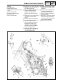
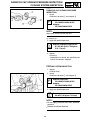
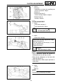
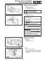
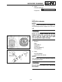
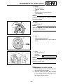
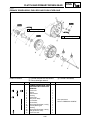
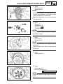
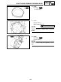
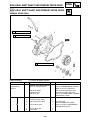
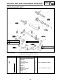
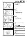
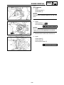
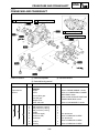
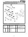
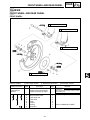
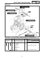
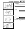
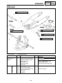
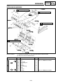
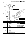
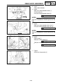
ENG
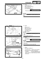
CLUTCH AND PR MARY DR VEN GEAR
å
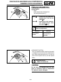
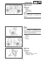
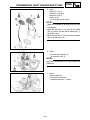
PR MARY DR VEN GEAR PUSH ROD AND PUSH EVER AX E
REMOVA PO N S
C
R m
N 1
w
C
2
3
NOTE
2
w
4 5
∫
C
4
5
M
å
∫
3
U
CDN
U
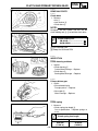
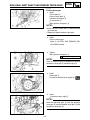
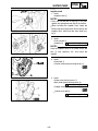
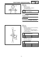
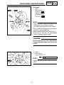
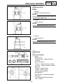
NSPEC ON
C
1
D m
2
W
D m
C
C
C
m
4
1
3
m
m
m
2
m
C
C
m
m
m
m
W
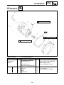
→R
→R
m
→R
a
D m
→R
G
W
M
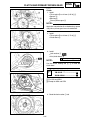
5
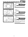
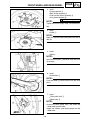
CDN
M
C
M
m
M
C
O
a
→ R
C
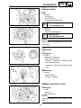
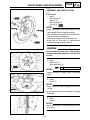
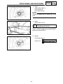
mm
4-33
m
mm
6
1
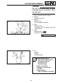
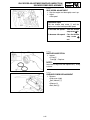
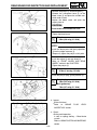
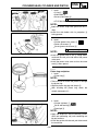
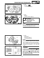
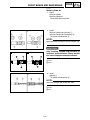
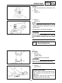
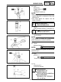
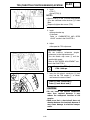
EC085002
2
GEN
INFO
SPEC
3
4
INSP
ADJ
ENG
5
6
CHAS
ELEC
7
TUN
0
q
w
e
r
t
y
u
i
o
p
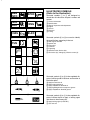
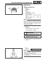
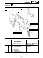
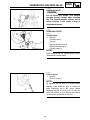
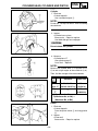
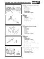
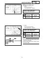
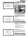
a
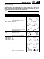
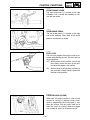
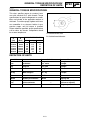
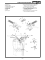
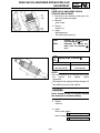
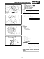
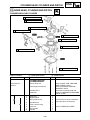
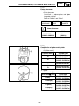
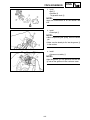
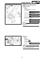
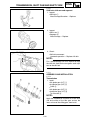
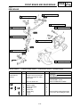
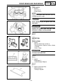
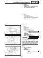
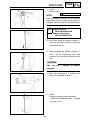
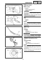
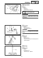
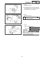
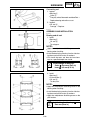
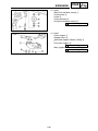
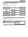
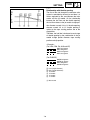
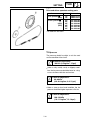
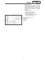
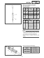
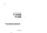
Illustrated symbols 1 to 7 are designed as
thumb tabs to indicate the chapter’s number and
content.
1 General information
2 Specifications
3 Regular inspection and adjustments
4 Engine
5 Chassis
6 Electrical
7 Tuning
Illustrated symbols 8 to r are used to identify
the specifications appearing in the text.
8 With engine mounted
9 Special tool
0 Filling fluid
q Lubricant
w Tightening
e Specified value, Service limit
r Resistance (Ω), Voltage (V), Electric current (A)
8
9
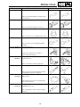
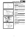
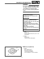
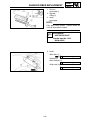
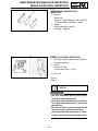
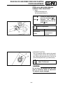
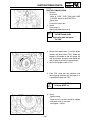
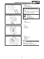
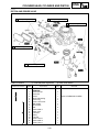
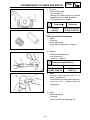
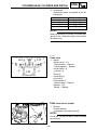
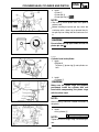
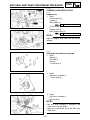
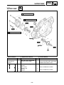
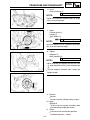
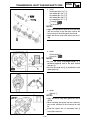
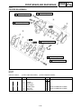
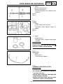
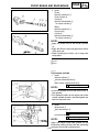
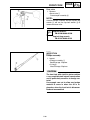
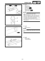
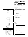
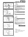
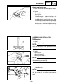
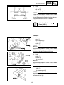
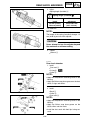
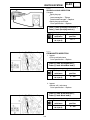
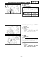
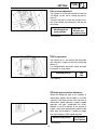
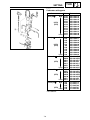
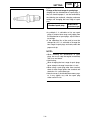
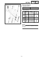
ILLUSTRATED SYMBOLS
(Refer to the illustration)
Illustrated symbols t to o in the exploded diagrams indicate grade of lubricant and location of
lubrication point.
t Apply transmission oil
y Apply engine mixing oil
u Apply molybdenum disulfide oil
i Apply lightweight lithium-soap base grease
o Apply molybdenum disulfide grease
Illustrated symbols p to a in the exploded diagrams indicate where to apply a locking agent
and where to install new parts.
p Apply locking agent (LOCTITER)
a Use new one
EC090000
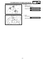
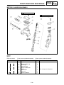
INDEX
GENERAL
INFORMATION
GEN
INFO
1
SPEC
2
INSP
ADJ
3
ENG
4
CHAS
5
ELEC
6
TUN
7
SPECIFICATIONS
REGULAR
INSPECTION AND
ADJUSTMENTS
ENGINE
CHASSIS
ELECTRICAL
TUNING
EC0A0000
CONTENTS
CHAPTER 1
GENERAL INFORMATION
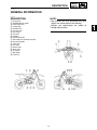
DESCRIPTION ............................................1-1
MACHINE IDENTIFICATION ......................1-2
IMPORTANT INFORMATION .....................1-3
CHECKING OF CONNECTION ..................1-6
SPECIAL TOOLS........................................1-7
CONTROL FUNCTIONS.............................1-9
FUEL AND ENGINE MIXING OIL.............1-12
STARTING AND BREAK-IN .....................1-13
TORQUE-CHECK POINTS.......................1-16
CLEANING AND STORAGE ....................1-17
CHAPTER 2
SPECIFICATIONS
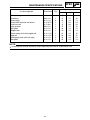
GENERAL SPECIFICATIONS ....................2-1
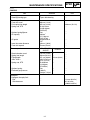
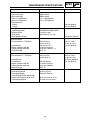
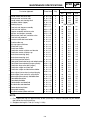
MAINTENANCE SPECIFICATIONS ...........2-3
GENERAL TORQUE SPECIFICATIONS..2-13
DEFINITION OF UNITS ............................2-13
CABLE ROUTING DIAGRAM ..................2-14
CHAPTER 3
REGULAR INSPECTION
AND ADJUSTMENTS
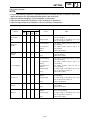
MAINTENANCE INTERVALS.....................3-1
PRE-OPERATION INSPECTION AND
MAINTENANCE ..........................................3-4
ENGINE.......................................................3-5
CHASSIS...................................................3-17
ELECTRICAL............................................3-38
CHAPTER 4
ENGINE
SEAT, FUEL TANK AND SIDE
COVERS .....................................................4-1
EXHAUST PIPE AND SILENCER ..............4-3
RADIATOR..................................................4-4
CARBURETOR AND REED VALVE...........4-7
CYLINDER HEAD , CYLINDER AND
PISTON .....................................................4-18
CLUTCH AND PRIMARY DRIVEN
GEAR .......................................................4-33
KICK AXLE, SHIFT SHAFT AND
PRIMARY DRIVE GEAR...........................4-40
YPVS GOVERNOR ...................................4-49
WATER PUMP ..........................................4-52
CDI MAGNETO .........................................4-56
ENGINE REMOVAL ..................................4-60
CRANKCASE AND CRANKSHAFT.........4-65
TRANSMISSION, SHIFT CAM AND
SHIFT FORK .............................................4-72
CHAPTER 5
CHASSIS
FRONT WHEEL AND REAR WHEEL ........5-1
FRONT BRAKE AND REAR BRAKE.......5-10
FRONT FORK ...........................................5-26
HANDLEBAR............................................5-41
STEERING ................................................5-48
SWINGARM ..............................................5-53
REAR SHOCK ABSORBER.....................5-61
CHAPTER 6
ELECTRICAL
ELECTRICAL COMPONENTS AND
WIRING DIAGRAM .....................................6-1
IGNITION SYSTEM.....................................6-2
SOLENOID VALVE SYSTEM .....................6-7
TPS (THROTTLE POSITION SENSOR)
SYSTEM......................................................6-9
CHAPTER 7
TUNING
ENGINE.......................................................7-1
CHASSIS...................................................7-13
DESCRIPTION
GEN
INFO
EC100000
GENERAL INFORMATION
EC110000
DESCRIPTION
NOTE:
1
2
3
4
5
6
7
8
9
0
q
w
e
r
t
y
u
i
o
9The machine you have purchased may differ
slightly from those shown in the following.
9Designs and specifications are subject to
change without notice.
Clutch lever
“ENGINE STOP” button
Front brake lever
Throttle grip
Radiator cap
Fuel tank cap
Kick starter
Fuel tank
Radiator
Coolant drain bolt
Check bolt (Transmission oil level)
Rear brake pedal
Valve joint
Fuel cock
Starter knob
Drive chain
Air cleaner
Shift pedal
Front fork
1-1
1
MACHINE IDENTIFICATION
GEN
INFO
EC120001
MACHINE IDENTIFICATION
There are two significant reasons for knowing
the serial number of your machine:
1. When ordering parts, you can give the number to your Yamaha dealer for positive identification of the model you own.
2. If your machine is stolen, the authorities will
need the number to search for and identify
your machine.
EC121001
VEHICLE IDENTIFICATION NUMBER
(For USA, CDN, AUS, NZ and E)
The vehicle identification number 1 is stamped
on the right of the steering head pipe.
EC122001
FRAME SERIAL NUMBER
(For F, D, GB, I and ZA)
The frame serial number 1 is stamped on the
right of the steering head pipe.
EC123001
ENGINE SERIAL NUMBER
The engine serial number 1 is stamped into the
elevated part of the right-side of the engine.
EC124000
MODEL LABEL
The model label 1 is affixed to the frame under
the rider’s seat. This information will be needed
to order spare parts.
1-2
IMPORTANT INFORMATION
GEN
INFO
EC130000
IMPORTANT INFORMATION
EC131010
PREPARATION FOR REMOVAL AND DIS
ASSEMBLY
1. Remove all dirt, mud, dust, and foreign
material before removal and disassembly.
When washing the machine with high pressured water, cover the parts as follows.
9Silencer exhaust port
9Side cover air intake port
9Water pump housing hole at the bottom
2. Use proper tools and cleaning equipment.
Refer to “SPECIAL TOOLS” section.
3. When disassembling the machine, keep
mated parts together. They include gears,
cylinders, pistons, and other mated parts
that have been “mated” through normal
wear. Mated parts must be reused as an
assembly or replaced.
4. During the machine disassembly, clean all
parts and place them in trays in the order of
disassembly. This will speed up assembly
time and help assure that all parts are correctly reinstalled.
5. Keep away from fire.
1-3
IMPORTANT INFORMATION
GEN
INFO
EC132000
ALL REPLACEMENT PARTS
1. We recommend to use Yamaha genuine
parts for all replacements. Use oil and/or
grease recommended by Yamaha for
assembly and adjustment.
EC133000
GASKETS, OIL SEALS AND O-RINGS
1. All gaskets, oil seals, and O-rings should be
replaced when an engine is overhauled. All
gasket surfaces, oil seal lips, and O-rings
must be cleaned.
2. Properly oil all mating parts and bearings
during reassembly. Apply grease to the oil
seal lips.
EC134000
LOCK WASHERS/PLATES AND COTTER
PINS
1. All lock washers/plates 1 and cotter pins
must be replaced when they are removed.
Lock tab(s) should be bent along the bolt or
nut flat(s) after the bolt or nut has been
properly tightened.
EC135001
BEARINGS AND OIL SEALS
1. Install the bearing (s) 1 and oil seal (s) 2
with their manufacturer’s marks or numbers
facing outward. (In other words, the
stamped letters must be on the side
exposed to view.) When installing oil seal(s),
apply a light coating of light-weight lithium
base grease to the seal lip(s). Oil the bearings liberally when installing.
cC
Do not use compressed air to spin the
bearings dry. This causes damage to the
bearing surfaces.
1-4
IMPORTANT INFORMATION
GEN
INFO
EC136000
CIRCLIPS
1. All circlips should be inspected carefully
before reassembly. Always replace piston
pin clips after one use. Replace distorted
circlips. When installing a circlip 1, make
sure that the sharp-edged corner 2 is positioned opposite to the thrust 3 it receives.
See the sectional view.
4 Shaft
1-5
CHECKING OF CONNECTION
GEN
INFO
EC1C0001
CHECKING OF CONNECTION
Dealing with stains, rust, moisture, etc. on the
connector.
1. Disconnect:
9Connector
2. Dry each terminal with an air blower.
3. Connect and disconnect the connector two
or three times.
4. Pull the lead to check that it will not come
off.
5. If the terminal comes off, bend up the pin 1
and reinsert the terminal into the connector.
6. Connect:
9Connector
NOTE:
The two connectors “click” together.
7. Check for continuity with a tester.
NOTE:
9If there in no continuity, clean the terminals.
9Be sure to perform the steps 1 to 7 listed
above when checking the wireharness.
9For a field remedy, use a contact revitalizer
available on the market.
9Use the tester on the connector as shown.
1-6
GEN
INFO
SPECIAL TOOLS
EC140002
SPECIAL TOOLS
The proper special tools are necessary for complete and accurate tune-up and assembly. Using the
correct special tool will help prevent damage caused by the use of improper tools or improvised techniques. The shape and part number used for the special tool differ by country, so two types are provided. Refer to the list provided to avoid errors when placing an order.
NOTE:
9For U.S.A. and Canada, use part number starting with “YM-”, “YU-” or “ACC -”.
9For others, use part number starting with “90890-”.
Part number
YU-1135-A, 90890-01135
Tool name / How to use
Crankcase separating tool
IIIustration
YU-1135-A
90890-01135
YM-1189
90890-01189
YU-1235
90890-01235
90890-01252
This tool is used to split the crankcase as well
as remove the crankshaft from either case.
YM-1189, 90890-01189
Flywheel puller
This tool is used to remove the flywheel magneto.
YU-1235, 90890-01235
Rotor holding tool
This tool is used when loosening or tightening the
flywheel magneto securing nut.
YU-3097, 90890-01252
Dial gauge and stand
YU-3097
YU-1256
Spark plug hole dial stand
YU-1256
These tools are used to set the ignition timing.
Crankcase installing tool
YU-90050, 90890-01274
Pot
YU-90050, 90890-01275
Bolt
YU-90063, 90890-01278
YU-90050
YU-90063
90890-01274
90890-01275
90890-01278
YU-1304
90890-01304
YU-24460-01
YU-33984
90890-01325
90890-01352
Adapter
These tools are used to install the crankshaft.
YU-1304, 90890-01304
Piston pin puller
This tool is used to remove the piston pin.
YU-24460-01,90890-01325
Radiator cap tester
YU-33984, 90890-01352
Adapter
These tools are used for checking the cooling
system.
1-7
GEN
INFO
SPECIAL TOOLS
Part number
YU-33975, 90890-01403
Tool name / How to use
Ring nut wrench
IIIustration
YU-33975
90890-01403
YM-01442
90890-01442
YM-01500
90890-01500
YM-01501
90890-01501
YM-3112-C
90890-03112
YU-8036-B
90890-03113
YM-91042
90890-04086
YM-34487
90890-06754
ACC-QUICK-GS-KT
90890-85505
This tool is used when tighten the steering ring nut
to specification.
YM-01442, 90890-01442
Fork seal driver
This tool is used when install the fork oil seal.
YM-01500, 90890-01500
Cap bolt wrench
This tool is used to loosen or tighten the base valve.
YM-01501, 90890-01501
Cap bolt ring wrench
This tool is used to loosen or tighten the damper
assembly.
YU-3112-C, 90890-03112
Yamaha pocket tester
Use this tool to inspect the coil resistance,
output voltage and amperage.
YU-8036-B
Inductive tachometer
90890-03113
Engine tachometer
This tool is needed for observing engine rpm.
YM-91042, 90890-04086
Clutch holding tool
This tool is used to hold the clutch when removing
or installing the clutch boss securing nut.
YM-34487
Dynamic spark tester
90890-06754
Ignition checker
This instrument is necessary for checking the ignition system components.
ACC-QUICK-GS-KT
90890-85505
Quick gasket ®
YAMAHA Bond No. 1215
This sealant (Bond) is used for crankcase mating
surface, etc.
1-8
CONTROL FUNCTIONS
GEN
INFO
EC150000
CONTROL FUNCTIONS
EC151000
“ENGINE STOP” BUTTON
The “ENGINE STOP” button 1 is located on the
left handlebar. Continue pushing the “ENGINE
STOP” button till the engine comes to a stop.
EC152000
CLUTCH LEVER
The clutch lever 1 is located on the left handlebar; it disengages or engages the clutch. Pull
the clutch lever to the handlebar to disengage
the clutch, and release the lever to engage the
clutch. The lever should be pulled rapidly and
released slowly for smooth starts.
EC153000
SHIFT PEDAL
The gear ratios of the constant-mesh 5 speed
transmission are ideally spaced. The gears can
be shifted by using the shift pedal 1 on the left
side of the engine.
EC154000
KICK STARTER
Rotate the kick starter 1 away from the engine.
Push the starter down lightly with your foot until
the gears engage, then kick smoothly and forcefully to start the engine. This model has a primary kick starter so the engine can be started in
any gear if the clutch is disengaged. In normal
practices, however, shift to neutral before starting.
EC155001
THROTTLE GRIP
The throttle grip 1 is located on the right handlebar; it accelerates or decelerates the engine.
For acceleration, turn the grip toward you; for
deceleration, turn it away from you.
1-9
CONTROL FUNCTIONS
GEN
INFO
EC156000
FRONT BRAKE LEVER
The front brake lever 1 is located on the right
handlebar. Pull it toward the handlebar to activate the front brake.
EC157000
REAR BRAKE PEDAL
The rear brake pedal 1 is located on the right
side of the machine. Press down on the brake
pedal to activate the rear brake.
EC158001
FUEL COCK
The fuel cock supplies fuel from the tank to carburetor while filtering the fuel. The fuel cock has
the two positions:
OFF: With the lever in this position, fuel will not
flow. Always return the lever to this position when the engine is not running.
ON: With the lever in this position, fuel flows to
the carburetor. Normal riding is done with
the lever in this position.
EC159000
STARTER KNOB (CHOKE)
When cold, the engine requires a richer air-fuel
mixture for starting. A separate starter circuit,
which is controlled by the starter knob 1, supplies this mixture. Pull the starter knob out to
open the circuit for starting. When the engine
has warmed up, push it in to close the circuit.
1-10
CONTROL FUNCTIONS
GEN
INFO
EC15R001
DETACHABLE SIDESTAND
This sidestand 1 is used to support only the
machine when standing or transporting it.
w
9Never apply additional force to the sidestand.
9Remove this sidestand before starting
out.
EC15F000
VALVE JOINT
This valve joint 1 prevents fuel from flowing out
and is installed to the fuel tank breather hose.
cC
In this installation, make sure the arrow
faces the fuel tank and also downward.
EC15f000
SET PIN
This set pin 1 is used to remove and install the
push rod of the engine.
cC
Be sure to use the set pin. If the set pin is
not used, the power valve constituent parts
will result in damage.
EC15e000
NIPPLE WRENCH
This nipple wrench 1 is used to tighten the
spoke.
1-11
FUEL AND ENGINE MIXING OIL
GEN
INFO
EC160051
FUEL AND ENGINE MIXING OIL
Mix oil with the gas at the ratio specified below.
Always use fresh, name-brand gasoline, and mix
the oil and gas the day of the race. Do not use
premix that is more than a few hours old.
Recommended fuel:
Premium unleaded gasoline
only with a research octane
number of 95 or higher.
NOTE:
If knocking or pinging occurs, use a different
brand of gasoline or higher octane grade.
cC
Never mix two types of oil in the same
batch; clotting of the oil could result. If you
wish to change oil types, be sure to drain
the fuel tank and the carburetor float bowl
of old premix prior to filling with the new
type.
Fuel tank capacity:
8.0 L (1.76 Imp gal, 2.11 US gal)
Mixing oil
Recommended oil:
Yamalube “2-R”
(Yamalube racing 2-cycle oil)
Mixing ratio: 30 : 1
If unavailable, use an equivalent
type of oil.
1-12
STARTING AND BREAK-IN
GEN
INFO
EC190000
STARTING AND BREAK-IN
cC
Before starting the machine, perform the
checks in the pre-operation check list.
w
Never start or run the engine in a closed
area. The exhaust fumes are poisonous;
they can cause loss of consciousness and
death in a very short time. Always operate
the machine in a well-ventilated area.
EC191001
STARTING A COLD ENGINE
1. Shift the transmission into neutral.
2. Turn the fuel cock to “ON” and full open the
starter knob (CHOKE).
3. With the throttle completely closed start the
engine by kicking the kick starter forcefully
with firm stroke.
4. Run the engine at idle or slightly higher until
it warms up: this usually takes about one or
two minutes.
5. The engine is warmed up when it responds
normally to the throttle with the starter knob
(CHOKE) turned off.
cC
Do not warm up the engine for extended periods.
EC193001
STARTING A WARM ENGINE
Do not operate the starter knob (CHOKE). Open
the throttle slightly and start the engine by kicking the kick starter forcefully with firm stroke.
cC
Observe the following break-in procedures
during initial operation to ensure optimum
performance and avoid engine damage.
1-13
STARTING AND BREAK-IN
GEN
INFO
EC194001
BREAK-IN PROCEDURES
1. Before starting the engine, fill the fuel tank
with a break-in oil-fuel mixture as follows.
Mixing oil:
Mixing ratio:
Yamalube “2-R”
15:1
2. Perform the pre-operation checks on the
machine.
3. Start and warm up the engine. Check the
idle speed, and check the operation of the
controls and the “ENGINE STOP” button.
4. Operate the machine in the lower gears at
moderate throttle openings for five to eight
minutes. Stop and check the spark plug
condition; it will show a rich condition during
break-in.
5. Allow the engine to cool. Restart the engine
and operate the machine as in the step
above for five minutes. Then, very briefly
shift to the higher gears and check full-throttle response. Stop and check the spark
plug.
6. After again allowing the engine to cool,
restart and run the machine for five more
minutes. Full throttle and the higher gears
may be used, but sustained full-throttle
operation should be avoided. Check the
spark plug condition.
7. Allow the engine to cool, remove the top
end, and inspect the piston and cylinder.
Remove any high spots on the piston with
#600 grit wet sandpaper. Clean all components and carefully reassemble the top end.
8. Drain the break-in oil-fuel mixture from the
fuel tank and refill with the specified mix.
9. Restart the engine and check the operation
of the machine throughout its entire operating range. Stop and check the spark plug
condition. Restart the machine and operate
it for about 10 to 15 more minutes. The
machine will now be ready to race.
1-14
STARTING AND BREAK-IN
GEN
INFO
cC
9After the break-in or before each race, you
must check the entire machine for loose fittings and fasteners as per “TORQUECHECK POINTS”.
Tighten all such fasteners as required.
9When any of the following parts have been
replaced, they must be broken in.
CYLINDER AND CRANKSHAFT:
About one hour of break-in operation is
necessary.
PISTON, RING AND GEARS:
These parts require about 30 minutes of
break-in operation at half-throttle or less.
Observe the condition of the engine carefully during operation.
1-15
TORQUE-CHECK POINTS
GEN
INFO
EC1A0013
TORQUE-CHECK POINTS
Frame construction
Combined seat and tank
Engine mounting
Frame to engine
Engine bracket to engine
Engine bracket to frame
Steering
Suspension
Wheel
Steering shaft to
handlebar
Steering shaft to frame
Steering shaft to handle crown
Handle crown to handlebar
Front
Steering shaft to
front fork
Front fork to handle crown
Front fork to under bracket
Rear
For link type
Assembly of links
Link to frame
Link to shock absorber
Link to swingarm
Rear
Installation of shock
absorber
Shock absorber to frame
Rear
Installation of swingarm
Tightening of pivot shaft
Installation of wheel
Front
Tightening of front axle
Tightening of axle holder
Tightening of rear axle
Wheel to sprocket
Rear
Brake
Frame to rear frame
Fuel tank to frame
Front
Caliper to front fork
Brake disc to wheel
Tightening of union bolt
Master cylinder to handlebar
Tightening of air bleeder
Tightening of brake hose holder
Rear
Brake pedal to frame
Brake disc to wheel
Tighening of union bolt
Master cylinder to frame
Tightening of air bleeder
Tightening of brake hose holder
Fuel system
Fuel tank to fuel cock
NOTE:
1-16
Concerning the tightening torque, refer to “
MAINTENANCE SPECIFICATIONS” section in
the CHAPTER 2.
CLEANING AND STORAGE
GEN
INFO
EC1B0000
CLEANING AND STORAGE
EC1B1000
CLEANING
Frequent cleaning of your machine will enhance
its appearance, maintain good overall performance, and extend the life of many components.
1. Before washing the machine, block off the
end of the exhaust pipe to prevent water
from entering. A plastic bag secured with a
rubber band may be used for this purpose.
2. If the engine is excessively greasy, apply
some degreaser to it with a paint brush. Do
not apply degreaser to the chain, sprockets,
or wheel axles.
3. Rinse the dirt and degreaser off with a garden hose; use only enough pressure to do
the job.
cC
Excessive hose pressure may cause water
seepage and contamination of wheel bearings, front forks, brakes and transmission
seals. Many expensive repair bills have
resulted from improper high pressure
detergent applications such as those available in coin-operated car washers.
4. After the majority of the dirt has been hosed
off, wash all surfaces with warm water and a
mild detergent. Use an old toothbrush to
clean hard-to-reach places.
5. Rinse the machine off immediately with
clean water, and dry all surfaces with a soft
towel or cloth.
6. Immediately after washing, remove excess
water from the chain with a paper towel and
lubricate the chain to prevent rust.
7. Clean the seat with a vinyl upholstery cleaner to keep the cover pliable and glossy.
8. Automotive wax may be applied to all painted or chromed surfaces. Avoid combination
cleaner-waxes, as they may contain abrasives.
9. After completing the above, start the engine
and allow it to idle for several minutes.
1-17
CLEANING AND STORAGE
GEN
INFO
EC1B2001
STORAGE
If your machine is to be stored for 60 days or
more, some preventive measures must be taken
to avoid deterioration. After cleaning the
machine thoroughly, prepare it for storage as follows:
1. Drain the fuel tank, fuel lines, and the carburetor float bowl.
2. Remove the spark plug, pour a tablespoon
of SAE 10W-30 motor oil in the spark plug
hole, and reinstall the plug. With the engine
stop switch pushed in, kick the engine over
several times to coat the cylinder walls with
oil.
3. Remove the drive chain, clean it thoroughly
with solvent, and lubricate it. Reinstall the
chain or store it in a plastic bag tied to the
frame.
4. Lubricate all control cables.
5. Block the frame up to raise the wheels off
the ground.
6. Tie a plastic bag over the exhaust pipe outlet to prevent moisture from entering.
7. If the machine is to be stored in a humid or
salt-air environment, coat all exposed metal
surfaces with a film of light oil. Do not apply
oil to rubber parts or the seat cover.
NOTE:
Make any necessary repairs before the machine
is stored.
1-18
GENERAL SPECIFICATIONS
SPEC
EC200000
SPECIFICATIONS
EC211000
GENERAL SPECIFICATIONS
Model name:
YZ250T1 (USA, CDN)
YZ250 (EUROPE, ZA)
YZ250T (AUS, NZ)
Model code number:
1P81 (USA, CDN, ZA)
1P82 (EUROPE)
1P84 (AUS, NZ)
Dimensions:
USA, ZA
AUS, NZ
EUROPE
CDN
2,179 mm
(85.8 in)
827 mm
(32.6 in)
1,306 mm
(51.4 in)
989 mm
(38.9 in)
1,481 mm
(58.3 in)
383 mm
(15.1 in)
←
2,188 mm
(86.1 in)
←
2,186 mm
(86.1 in)
←
1,310 mm
(51.6 in)
992 mm
(39.1 in)
1,485 mm
(58.5 in)
386 mm
(15.2 in)
1,309 mm
(51.5 in)
←
Overall length
Overall width
Overall height
Seat height
Wheelbase
Minimum ground clearance
Dry weight:
Without oil and fuel
Engine:
Engine type
Cylinder arrangement
Displacement
Bore × Stroke
Compression ratio
Starting system
Lubrication system:
Oil type or grade (2-Cycle):
Transmission oil
Periodic oil change
Total amount
←
←
←
←
←
Liquid cooled 2-stroke, gasoline
Single cylinder, forward inclined
249 cm3 (8.76 lmp oz, 8.42 US oz)
66.4 × 72 mm (2.614 × 2.835 in)
9.1~10.9 : 1 (Expect for EUROPE)
9.0~10.6 : 1 (For EUROPE)
Kick starter
Premix (30 : 1)(Yamalube 2-R)
Yamalube 4 (10W-30) or SAE 10W-30 type SE
motor oil
0.75 L (0.66 Imp qt, 0.79 US qt)
0.80 L (0.70 Imp qt, 0.85 US qt)
1.20 L (1.06 Imp qt, 1.27 US qt)
Air filter:
Wet type element
Tank capacity
←
96.0 kg (211.6 lb)
Coolant capacity (including all routes):
Fuel:
Type
←
Premium unleaded gasoline
only with a research octane
number of 95 or higher
8.0 L (1.76 Imp gal, 2.11 US gal)
2-1
2
SPEC
GENERAL SPECIFICATIONS
Carburetor:
Type/Manufacturer
PWK38S/KEIHIN
Spark plug:
Type/Manufacturer
Gap
BR8EG/NGK (resistance type)
0.5~0.6 mm (0.020~0.024 in)
Clutch type:
Wet, multiple-disc
Transmission:
Primary reduction system
Primary reduction ratio
Secondary reduction system
Secondary reduction ratio
Transmission type
Operation
Gear ratio: 1st
2nd
3rd
4th
5th
Chassis:
Frame type
Caster angle
Trail
USA, ZA, AUS, NZ
←
←
←
49/14 (3.500)
←
Gear
63/21 (3.000)
Chain drive
50/14 (3.571)
Constant mesh,
5-speed
Left foot operation
27/14 (1.929)
23/15 (1.533)
23/18 (1.278)
24/22 (1.091)
20/21 (0.952)
USA, ZA, AUS, NZ
Semi double
cradle
26.9°
115 mm (4.53 in)
EUROPE, CDN
←
←
←
←
←
←
EUROPE
CDN
←
←
27.0°
117 mm (4.61 in)
26.9°
116 mm (4.57 in)
Tire:
Type
Size (front)
Size (rear)
Tire pressure (front and rear)
With tube
80/100-21 51M
110/90-19 62M
100 kPa (1.0 kgf/cm2, 15 psi)
Brake:
Front brake type
Operation
Rear brake type
Operation
Single disc brake
Right hand operation
Single disc brake
Right foot operation
Suspension:
Front suspension
Rear suspension
Telescopic fork
Swingarm (link type monocross suspension)
Shock absorber:
Front shock absorber
Rear shock absorber
Coil spring/oil damper
Coil spring/Gas, oil damper
Wheel travel:
Front wheel travel
Rear wheel travel
300 mm (11.8 in)
315 mm (12.4 in)
Electrical:
Ignition system
CDI magneto
2-2
MAINTENANCE SPECIFICATIONS
SPEC
EC212000
MAINTENANCE SPECIFICATIONS
EC212100
ENGINE
Item
Cylinder head:
Combustion chamber capacity
Warp limit
Cylinder:
Bore size
Taper limit
Out of round limit
Piston:
Piston size/
Measuring point*
Piston clearance
Piston offset
Piston pin:
Piston pin outside diameter
Piston ring:
Sectional sketch
End gap (installed)
Side clearance (installed) : 1st
: 2nd
Standard
USA, CDN, ZA,
AUS, NZ
EUROPE
21.0 cm3
(0.739 Imp oz,
0.710 US oz)
…
21.5 cm3
(0.757 Imp oz,
0.727 US oz)
…
66.400~66.414 mm
(2.6142~2.6147 in)
…
…
Limit
…
0.03 mm (0.0012 in)
66.5 mm (2.618 in)
0.05 mm (0.0020 in)
0.01 mm (0.0004 in)
…
66.352~66.367 mm
(2.6120~2.6129 in)
17.5 mm (0.69 in)
0.045~0.050 mm
(0.0018~0.0020 in)
1.5 mm (0.059 in)/EX-side
…
0.1 mm (0.004 in)
17.995~18.000 mm
(0.7085~0.7087 in)
17.975 mm
(0.7077 in)
Plain
B=1.0 mm (0.039 in)
T=2.55 mm (0.100 in)
0.40~0.55 mm (0.016~0.022 in)
0.030~0.065 mm (0.0012~0.0026 in)
0.030~0.065 mm (0.0012~0.0026 in)
…
…
…
0.95 mm (0.037 in)
0.1 mm (0.004 in)
0.1 mm (0.004 in)
59.95~60.00 mm (2.360~2.362 in)
0.03 mm (0.0012 in)
…
0.25~0.75 mm (0.010~0.030 in)
0.4~1.0 mm (0.016~0.039 in)
…
2.9~3.1 mm (0.114~0.122 in)
8
1.5~1.7 mm (0.059~0.067 in)
7
…
50.0 mm (1.969 in)
6
2.8 mm (0.110 in)
…
…
…
0.2 mm (0.008 in)
48.0 mm (1.890 in)
…
…
Crankshaft:
Crank width “A”
Runout limit “C”
Connecting rod big end
side clearance “D”
Small end free play “F”
Clutch:
Friction plate thickness
Quantity
Clutch plate thickness
Quantity
Warp limit
Clutch spring free length
Quantity
2-3
0.05 mm (0.0020 in)
2.0 mm (0.08 in)
MAINTENANCE SPECIFICATIONS
Item
SPEC
Standard
Clutch housing thrust clearance
Clutch housing radial clearance
Clutch release method
Limit
0.17~0.23 mm (0.007~0.009 in)
0.030~0.055 mm (0.001~0.002 in)
Inner push, cam push
…
…
…
Transmission:
Main axle deflection limit
Drive axle deflection limit
…
…
0.01 mm (0.0004 in)
0.01 mm (0.0004 in)
Shifter:
Shifting type
Guide bar bending limit
Cam drum and guide bar
…
Kick starter type:
Kick and ratchet type
…
0.05 mm (0.0020 in)
…
Air filter oil grade (oiled filter):
Foam-air-filter oil or equivalent oil
…
Carburetor:
USA, CDN, ZA,
AUS, NZ
Type/Manufacturer
I.D. mark
Main jet
Main air jet
Jet needle-clip position
Main nozzle
Cutaway
Pilot jet
Pilot air screw
(for reference only)
Valve seat size
Starter jet
Power jet
Float arm height
(M.J.)
(M.A.J)
(J.N.)
(N.J.)
(C.A.)
(P.J.)
(P.A.S.)
(V.S.)
(G.S.)
(P.W.J.)
(F.H.)
Reed valve:
Thickness*
Valve stopper height
Valve bending limit
Cooling:
Radiator core size:
Width
Height
Thickness
Radiator cap opening pressure
Radiator capacity (total)
Water pump:
Type
EUROPE
PWK38S/KEIHIN
1P81 00
#178
#200
N3EJ-2
ø2.9
#7
#50
1
←
1P82 10
#180
←
N3EW-3
←
←
#52
7/8
…
…
…
…
…
…
…
…
…
ø3.8 mm (0.15 in)
#85
#50
5.5~7.5 mm
(0.22~030 in)
←
←
←
←
…
…
…
…
0.42 mm (0.017 in)
10.3~10.7 mm (0.406~0.421 in)
…
…
…
107.8 mm (4.24 in)
240 mm (9.45 in)
32 mm (1.26 in)
95~125 kPa
(0.95~1.25 kg/cm2, 13.5~17.8 psi)
0.63 L (0.55 Imp qt, 0.67 US qt)
…
…
…
…
Single-suction centrifugal pump
…
2-4
0.2 mm (0.008 in)
…
SPEC
MAINTENANCE SPECIFICATIONS
Tightening torque
Part to be tightened
▲
▲
▲
▲
▲
▲
Spark plug
Cylinder head (nut)
(stud)
Cylinder (nut)
(stud)
Power valve :
Holder
Link rod
Push rod
Thrust plate
Side holder
Link lever
Pulley
Cover
Governor fork
Housing
Impeller
Water pump housing cover
Coolant drain bolt
Radiator
Radiator panel
Radiator hose clamp
Air filter element
Carburetor joint
Air filter case
Air filter guide clamp
Reed valve
Throttle cable adjust bolt and locknut
Throttle cable
Exhaust pipe (front)
Exhaust pipe (rear)
Exhaust pipe stay (front)
Exhaust pipe stay (rear)
Silencer
Fiber (silencer)
Crankcase
Crankcase cover (left)
Chain cover
Crankcase cover (right)
Bearing plate cover (drive axle left)
Bearing plate cover (main axle right)
Holder
Oil drain bolt
Oil check bolt
Kick starter
Ratchet wheel stopper
Clutch cover
Thread size
Q’ty
Nm
m•kg
ft•lb
M14S × 1.25
M 8 × 1.25
M 8 × 1.25
M10 × 1.25
M10 × 1.25
1
6
6
4
4
20
25
13
42
13
2.0
2.5
1.3
4.2
1.3
14
18
9.4
30
9.4
M 5 × 0.8
M 5 × 0.8
M 5 × 0.8
M 5 × 0.8
M 5 × 0.8
M 4 × 0.7
M 4 × 0.7
M 5 × 0.8
M 4 × 0.7
M 5 × 0.8
M 8 × 1.25
M 6 × 1.0
M 6 × 1.0
M 6 × 1.0
M 6 × 1.0
M 6 × 1.0
M 6 × 1.0
M 6 × 1.0
M 6 × 1.0
M 5 × 0.8
M 3 × 0.5
M 8 × 1.25
M 6 × 0.75
M 6 × 1.0
M 6 × 1.0
M 8 × 1.25
M 6 × 1.0
M 6 × 1.0
M 6 × 1.0
M 6 × 1.0
M 6 × 1.0
M 6 × 1.0
M 6 × 1.0
M 6 × 1.0
M 6 × 1.0
M 6 × 1.0
M12 × 1.5
M 6 × 1.0
M 8 × 1.25
M 6 × 1.0
M 6 × 1.0
2
2
1
1
4
1
2
4
2
4
1
4
1
6
2
8
1
5
4
1
4
1
1
1
1
1
1
2
2
11
5
2
9
2
2
2
1
1
1
2
6
6
6
5
6
4
4
4
4
5
5
14
10
10
10
10
1
2
10
8
1
1
7
4
14
12
25
12
12
10
14
8
8
10
10
10
10
20
10
30
10
10
0.6
0.6
0.5
0.6
0.4
0.4
0.4
0.4
0.5
0.5
1.4
1.0
1.0
1.0
1.0
0.1
0.2
1.0
0.8
0.1
0.1
0.7
0.4
1.4
1.2
2.5
1.2
1.2
1.0
1.4
0.8
0.8
1.0
1.0
1.0
1.0
2.0
1.0
3.0
1.0
1.0
4.3
4.3
3.6
4.3
2.9
2.9
2.9
2.9
3.6
3.6
10
7.2
7.2
7.2
7.2
0.7
1.4
7.2
5.8
0.7
0.7
5.1
2.9
10
8.7
18
8.7
8.7
7.2
10
5.8
5.8
7.2
7.2
7.2
7.2
14
7.2
22
7.2
7.2
2-5
SPEC
MAINTENANCE SPECIFICATIONS
Tightening torque
Part to be tightened
Primary drive gear
Clutch boss
Clutch spring
Clutch cable adjust bolt and locknut
Push lever axle
Drive sprocket
Shift guide
Stopper lever
Torsion spring (shift shaft) stopper bolt
Segment
Bearing plate cover (shift cam right)
Shift pedal
Thread size
M10 × 1.25
M20 × 1.0
M 6 × 1.0
M 6 × 0.75
M 5 × 0.8
M20 × 1.0
M 6 × 1.0
M 6 × 1.0
M 8 × 1.25
M 8 × 1.25
M 6 × 1.0
M 6 × 1.0
Q’ty
1
1
6
1
1
1
2
1
1
1
2
1
Nm
m•kg
ft•lb
55
75
10
4
6
75
10
10
22
30
10
10
5.5
7.5
1.0
0.4
0.6
7.5
1.0
1.0
2.2
3.0
1.0
1.0
40
54
7.2
2.9
4.3
54
7.2
7.2
16
22
7.2
7.2
NOTE:
- marked portion shall be checked for torque tightening after break-in or before each race.
2-6
MAINTENANCE SPECIFICATIONS
SPEC
EC212201
CHASSIS
Item
Steering system:
Steering bearing type
Front suspension:
Front fork travel
Fork spring free length
Spring rate, STD
Optional spring/Spacer
Oil capacity
Oil grade
Inner tube outer diameter
Front fork top end
Rear suspension:
Shock absorber travel
Spring free length
Fitting length
<Min.~Max.>
Spring rate, STD
Optional spring
Enclosed gas pressure
Swingarm:
Swingarm free play limit
End
Side clearance
Standard
Limit
Taper roller bearing
…
300 mm (11.8 in)
465 mm (18.3 in)
K=4.3 N/mm
(0.438 kg/mm,
24.5 lb/in)
Yes
430 cm3
(15.1 Imp oz,
14.5 US oz)
Suspension oil
“S1”
48 mm (1.89 in)
Zero mm (Zero in)
…
460 mm (18.1 in)
…
…
…
…
…
…
USA, CDN, ZA,
AUS,NZ
132 mm (5.20 in)
260 mm (10.24 in)
251 mm (9.88 in)
240.5~258.5 mm
(9.47~10.18 in)
K=48 N/mm
(4.9 kg/mm,
274.4 lb/in)
Yes
1,000 kPa
(10 kg/cm2, 142 psi)
…
…
EUROPE
←
←
253 mm (9.96 in)
←
…
…
…
…
←
…
←
←
…
…
1.0 mm (0.04 in)
0.2~0.9 mm
(0.008~0.035 in)
2-7
MAINTENANCE SPECIFICATIONS
Item
SPEC
Standard
Limit
Wheel:
Front wheel type
Rear wheel type
Front rim size/Material
Rear rim size/Material
Rim runout limit:
Radial
Lateral
Spoke wheel
Spoke wheel
21 × 1.60/Aluminum
19 × 2.15/Aluminum
…
…
…
…
…
…
2.0 mm (0.08 in)
2.0 mm (0.08 in)
Drive chain
Type/Manufacturer
Number of links
Chain slack
Chain length (15 links)
DID520DMA2 SDH/DAIDO
113 links + joint
48~58 mm (1.9~2.3 in)
…
…
…
…
250 × 3.0 mm
(9.84 × 0.12 in)
4.4 mm (0.17 in)
11.0 mm (0.433 in)
27.0 mm (1.063 in) × 2
DOT #4
250 × 2.5 mm
(9.84 × 0.10 in)
1.0 mm (0.04 in)
…
…
…
245 × 4.0 mm
(9.65 × 0.16 in)
…
6.4 mm (0.25 in)
11.0 mm (0.433 in)
25.4 mm (1.000 in)
DOT #4
245 × 3.5 mm
(9.65 × 0.14 in)
0.15 mm (0.006 in)
1.0 mm (0.04 in)
…
…
…
95 mm (3.74 in)
Zero mm (Zero in)
…
…
8~13 mm (0.31~0.51 in)
3~5 mm (0.12~0.20 in)
…
…
Front disc brake:
Disc outside dia. × Thickness
Pad thickness
Master cylinder inside dia.
Caliper cylinder inside dia.
Brake fluid type
Rear disc brake:
Disc outside dia. × Thickness
Deflection limit
Pad thickness
Master cylinder inside dia.
Caliper cylinder insdie dia.
Brake fluid type
Brake lever & brake pedal:
Brake lever position
Brake pedal height
(vertical height above footrest top)
Clutch lever free play (lever end)
Throttle grip free play
2-8
242.9 mm (9.563 in)
SPEC
MAINTENANCE SPECIFICATIONS
Tightening torque
Part to be tightened
Thread size
Q’ty
Nm
Handle crown and outer tube
Under bracket and outer tube
Handle crown and steering shaft
Handlebar holder (upper)
Steering ring nut
Front fork and damper assembly
Front fork and adjuster
Damper assembly and base valve
Adjuster and damper assembly
Bleed screw (front fork) and base valve
Front fork and protector
Protector and brake hose holder
Throttle cable cap
Grip cap upper and lower
Clutch lever (nut)
Clutch lever holder
Front brake master cylinder and bracket
Front brake master cylinder cap
Brake lever mounting (bolt)
Brake lever mounting (nut)
Brake lever position locknut
Cable guide (front brake hose) and under bracket
Front brake hose union bolt (master cylinder)
Front brake hose union bolt (caliper)
Front brake caliper and front fork
Front brake caliper and brake hose holder
Brake caliper (front and rear) and pad pin plug
Brake caliper (front and rear) and pad pin
Brake caliper (front and rear) and bleed screw
Front wheel axle and nut
Front wheel axle holder
Front brake disc and wheel hub
Rear brake disc and wheel hub
Footrest bracket and frame
Brake pedal mounting
Rear brake master cylinder and frame
M 8 × 1.25
M 8 × 1.25
M24 × 1.0
M 8 × 1.25
M28 × 1.0
M51 × 1.5
M22 × 1.25
M42 × 1.5
M12 × 1.25
M 5 × 0.8
M 6 × 1.0
M 6 × 1.0
M 4 × 0.7
M 6 × 1.0
M 6 × 1.0
M 5 × 0.8
M 6 × 1.0
M 4 × 0.7
M 6 × 1.0
M 6 × 1.0
M 6 × 1.0
M 6 × 1.0
M10 × 1.25
M10 × 1.25
M 8 × 1.25
M 6 × 1.0
M10 × 1.0
M10 × 1.0
M 8 × 1.25
M16 × 1.5
M 8 × 1.25
M 6 × 1.0
M 6 × 1.0
M10 × 1.25
M 8 × 1.25
M 6 × 1.0
4
4
1
4
1
2
2
2
2
2
6
2
2
2
1
2
2
2
1
1
1
1
1
1
2
1
2
2
2
1
4
6
6
4
1
2
m•kg
ft•lb
2.3
17
2.0
14
14.5
105
2.8
20
Refer to NOTE.
3.0
30
22
5.5
55
40
2.9
29
21
2.9
29
21
0.1
1
0.7
1.0
10
7.2
0.7
7
5.1
0.1
1
0.7
0.4
4
2.9
0.4
4
2.9
0.4
4
2.9
0.9
9
6.5
0.2
2
1.4
0.6
6
4.3
0.6
6
4.3
0.5
5
3.6
0.4
4
2.9
3.0
30
22
3.0
30
22
2.3
23
17
1.0
10
7.2
0.3
3
2.2
1.8
18
13
0.6
6
4.3
10.5
105
75
2.3
23
17
1.2
12
8.7
1.4
14
10
5.5
55
40
2.6
26
19
1.0
10
7.2
23
20
145
28
NOTE:
1. First, tighten the ring nut approximately 38 Nm (3.8 m•kg, 27 ft•lb) by using the ring nut wrench,
then loosen the ring nut one turn.
2. Retighten the ring nut 7 Nm (0.7 m•kg, 5.1 ft•lb).
2-9
SPEC
MAINTENANCE SPECIFICATIONS
Tightening torque
Part to be tightened
Rear brake master cylinder cap
Rear brake hose union bolt (caliper)
Rear brake hose union bolt (master cylinder)
Rear wheel axle and nut
Driven sprocket and wheel hub
Nipple (spoke)
Disc cover and rear brake caliper
Protector and rear brake caliper
Chain puller adjust bolt and locknut
Engine mounting:
Engine bracket and frame
Engine and frame (front)
Engine and frame (upper)
Engine and frame (lower)
Pivot shaft and nut
Relay arm and swingarm
Relay arm and connecting rod
Connecting rod and frame
Rear shock absorber and frame
Rear shock absorber and relay arm
Rear frame and frame (upper)
Rear frame and frame (lower)
Swingarm and brake hose holder
Swingarm and patch
Drive chain tensioner mounting
Chain support and swingarm
Seal guard and swingarm
Cable guide and frame
Fuel tank mounting boss and frame
Fuel tank mounting
Fuel tank and fuel cock
Fuel tank and seat set bracket
Fuel tank and hooking screw (fitting band)
Fuel tank and fuel tank bracket
Seat mounting
Side cover mounting
Air scoop and fuel tank
Air scoop and panel
Front fender mounting
Rear fender mounting (front)
Rear fender mounting (rear)
Number plate
Thread size
Q’ty
Nm
m•kg
ft•lb
M 4 × 0.7
M10 × 1.25
M10 × 1.25
M20 × 1.5
M 8 × 1.25
–
M 6 × 1.0
M 6 × 1.0
M 8 × 1.25
2
1
1
1
6
72
2
2
2
2
30
30
125
42
3
7
7
16
0.2
3.0
3.0
12.5
4.2
0.3
0.7
0.7
1.6
1.4
22
22
90
30
2.2
5.1
5.1
11
M 8 × 1.25
M10 × 1.25
M10 × 1.25
M10 × 1.25
M16 × 1.5
M14 × 1.5
M14 × 1.5
M14 × 1.5
M10 × 1.25
M10 × 1.25
M 8 × 1.25
M 8 × 1.25
M 5 × 0.8
M 4 × 0.7
M 8 × 1.25
M 6 × 1.0
M 5 × 0.8
M 5 × 0.8
M10 × 1.25
M 6 × 1.0
M 6 × 1.0
M 6 × 1.0
M 6 × 1.0
M 6 × 1.0
M 8 × 1.25
M 6 × 1.0
M 6 × 1.0
M 6 × 1.0
M 6 × 1.0
M 6 × 1.0
M 6 × 1.0
M 6 × 1.0
2
1
1
1
1
1
1
1
1
1
1
2
4
4
2
3
4
2
2
2
2
1
1
4
2
2
4
2
4
2
2
1
34
64
64
64
85
80
80
80
56
53
32
29
1
2
19
7
5
4
20
10
7
7
7
7
19
7
7
6
7
7
12
7
3.4
6.4
6.4
6.4
8.5
8.0
8.0
8.0
5.6
5.3
3.2
2.9
0.1
0.2
1.9
0.7
0.5
0.4
2.0
1.0
0.7
0.7
0.7
0.7
1.9
0.7
0.7
0.6
0.7
0.7
1.2
0.7
24
46
46
46
61
58
58
58
40
38
23
21
0.7
1.4
13
5.1
3.6
2.9
14
7.2
5.1
5.1
5.1
5.1
13
5.1
5.1
4.3
5.1
5.1
8.7
5.1
NOTE:
- marked portion shall be checked for torque tightening after break-in or before each race.
2-10
SPEC
MAINTENANCE SPECIFICATIONS
EC212300
ELECTRICAL
Item
Ignition system:
Ignition timing (B.T.D.C.)
Advancer type
Standard
Limit
0.18 mm (0.007 in)
Electrical
…
…
…
…
CDI unit-model/Manufacturer
5CU-10/YAMAHA
720~1,080 Ω at 20°C (68°F)
(Black-Black/Red)
44~66 Ω at 20°C (68°F)
(Green/Blue-Green/White)
248~372 Ω at 20°C (68°F)
(White/Blue-White/Red)
5NX-01/YAMAHA
Ignition coil:
Model/Manufacturer
Minimum spark gap
Primary winding resistance
Secondary winding resistance
1P8-00/YAMAHA
6 mm (0.24 in)
0.20~0.30 Ω at 20°C (68°F)
9.5~14.3 kΩ at 20°C (68°F)
…
…
…
…
Spark plug cap:
Resistance
4~6 kΩ at 20°C (68°F)
…
CDI:
Magneto-model (stator)/Manufacturer
Source coil 1 resistance (color)
Source coil 2 resistance (color)
Pickup coil resistance (color)
…
…
…
Tightening torque
Part to be tightened
Stator
Rotor
Ignition coil
Thread size
M 6 × 1.0
M12 × 1.25
M 6 × 1.0
2-12
Q’ty
3
1
2
Nm
m•kg
ft•lb
8
56
7
0.8
5.6
0.7
5.8
40
5.1
GENERAL TORQUE SPECIFICATIONS/
DEFINITION OF UNITS
SPEC
EC220001
GENERAL TORQUE SPECIFICATIONS
This chart specifies torque for standard fasteners with standard I.S.O. pitch threads. Torque
specifications for special components or assemblies are included in the applicable sections of
this book. To avoid warpage, tighten multi-fastener assemblies in a crisscross fashion, in progressive stages, until full torque is reached.
Unless otherwise specified, torque specifications
call for clean, dry threads. Components should
be at room temperature.
A: Distance across flats
B: Outside thread diameter
TORQUE SPECIFICATION
A
(Nut)
B
(Bolt)
10 mm
12 mm
14 mm
17 mm
19 mm
22 mm
6 mm
8 mm
10 mm
12 mm
14 mm
16 mm
Nm
m•kg
ft•lb
6
15
30
55
85
130
0.6
1.5
3.0
5.5
8.5
13
4.3
11
22
40
61
94
EC230000
DEFINITION OF UNITS
Unit
Read
Definition
Measure
mm
cm
milimeter
centimeter
10- meter
10-2 meter
Length
Length
kg
kilogram
103 gram
Weight
N
Newton
1 kg × m/sec2
Force
Nm
m•kg
Newton meter
Meter kilogrma
N×m
m × kg
Torque
Torque
Pa
Pascal
N/m2
Pressure
N/mm
Newton per millimeter
N/mm
Spring rate
L
cm3
Liter
Cubic centimeter
—
—
Volume or capacity
Volume or capacity
r/min
Revolution per minute
—
Engine speed
3
2-13
CABLE ROUTING DIAGRAM
SPEC
EC240000
CABLE ROUTING DIAGRAM
1
2
3
4
5
6
7
Radiator hose
Throttle cable
Clutch cable
“ENGINE STOP” button lead
Radiator breather hose
C.D.I. magneto lead
Ignition coil lead
A Pass the clutch cable on the out- H Pass the clutch cable in front of
side of the throttle cable and
the center of the cylinder head
“ENGINE STOP” button lead.
tightening nut.
B Pass through the cable guide the I Pass the air vent hose, overflow
throttle cable, “ENGINE STOP”
hose and crankcase breather
button lead and clutch cable.
hose between the frame and
C Align the throttle cable locating
connecting rod.
tape with the cable guide.
J Locate the clamp ends in the
D Pass above the radiator hose the
arrowed range.
throttle cable, “ENGINE STOP”
button lead and clutch cable.
E Clamp the “ENGINE STOP” button lead to the frame.
F Clamp to the frame the throttle
cable, clutch cable, TPS (throttle
position sensor) lead and solenoid valve lead.
G Clamp to the frame the throttle
cable, TPS (throttle position sensor) lead and solenoid valve
lead.
2-14
CABLE ROUTING DIAGRAM
1
2
3
4
5
6
7
8
Clamp
Radiator hose
Solenoid valve lead
TPS (throttle position sensor)
lead
Air vent hose (left)
Crankcase breather hose
Overflow hose
Air vent hose (right)
A Insert the tip of the fuel tank
breather hose into the hole in
the steering shaft cap.
B Pass the radiator breather hose,
ignition coil lead and C.D.I.
magneto lead between the
frame and the left of the radiator.
C Clamp the C.D.I. magneto lead
and ignition coil lead to the
frame.
D Install the side core and ignition
coil together to the frame.
E Pass the radiator breather hose
from the outside of the engine
bracket to the inside of the
downtube. Pass the radiator
breather hose on the inside of
the C.D.I. magneto lead.
F Clamp the C.D.I. magneto lead,
radiator breather hose and
Y.P.V.S. breather hose.
2-15
SPEC
G Clamp to the frame the radiator
breather hose and C.D.I. magneto lead.
H Pass the C.D.I. magneto lead
and radiator breather hose in
front of the radiator hose.
I Pass the throttle cable behind
the air vent hose.
J Pass the air vent hose, overflow
hose and crankcase breather
hose so that they do not contact
the rear shock absorber.
K Clamp the air vent hoses.
CABLE ROUTING DIAGRAM
1
2
3
4
5
6
7
8
9
0
Clamp
High tension cord
C.D.I.unit
“ENGINE STOP” button lead
Ignition coil lead
Radiator hose
Radiator breather hose
Throttle cable
Clutch cable
Wireharness
A Clamp the wireharness to the
right engine bracket.
B Pass the high tension cord to
the right of the radiator hose.
C Pass the C.D.I. unit lead
between the frame and the right
side of the radiator and then
above the radiator fitting boss.
D Pass the radiator breather hose
behind the radiator hose.
E Locate the clamp ends in the
arrowed range.
F Insert the C.D.I. unit band until it
stops at the C.D.I. unit stay.
2-16
SPEC
CABLE ROUTING DIAGRAM
SPEC
A Install the brake hose so that its pipe portion
directs as shown and lightly touches the projection on the caliper.
B Pass the brake hose into the brake hose
holders.
C If the brake hose contacts the spring (rear
shock absorber), correct its twist.
D Install the brake hose so that its pipe portion
directs as shown and lightly touches the
projection on the master cylinder.
1 Master cylinder
2 Brake hose holder
3 Brake hose
2-17
CABLE ROUTING DIAGRAM
1
2
3
4
5
6
7
8
Brake hose
Master cylinder
“ENGINE STOP” button lead
“ENGINE STOP” button
Throttle cable
Clutch cable
Clamp
Cable guide
SPEC
A Install the brake hose so that its pipe portion
directs as shown and lightly touches the
projection on the master cylinder.
B Pass the “ENGINE STOP” button lead in
the middle of the clutch holder.
C Clamp the “ENGINE STOP” button lead to
the handlebar to 3 clicks.
D Pass the brake hose in front of the number
plate and through the cable guide.
2-18
MAINTENANCE INTERVALS
INSP
ADJ
EC300000
REGULAR INSPECTION AND ADJUSTMENTS
EC310013
MAINTENANCE INTERVALS
The following schedule is intended as a general guide to maintenance and lubrication. Bear in mind
that such factors as weather, terrain, geographical location, and individual usage will alter the required
maintenance and lubrication intervals. If you are a doubt as to what intervals to follow in maintaining
and lubricating your machine, consult your Yamaha dealer.
Item
After
Every
breakrace
in
PISTON
Inspect and clean
Replace
●
●
PISTON RING
Inspect
Replace
●
●
PISTON PIN, SMALL END BEARING
Inspect
Replace
CYLINDER HEAD
Inspect and clean
Retighten
CYLINDER
Inspect and clean
Replace
YPVS
Inspect and clean
CLUTCH
Inspect and adjust
Replace
TRANSMISSION
Replace oil
Inspect
Replace bearing
Every
third
Every As refifth quired
●
●
●
●
●
●
●
●
●
●
●
●
●
Inspect carbon deposits
and eliminate them
Check gasket
●
MUFFLER
Inspect
Clean
Retighten
●
●
Inspect housing, friction
plate, clutch plate and
spring
Yamalube 4 (10W-30) or
SAE 10W-30 SE motor oil
Inspect wear
●
●
●
●
●
CRANK
Inspect and clean
CARBURETOR
Inspect, adjust and clean
●
●
●
●
Inspect score marks
Inspect wear
Inspect carbon deposits
and eliminate them
SHIFT FORK, SHIFT CAM, GUIDE BAR
Inspect
ROTOR NUT
Retighten
Inspect crack
Inspect carbon deposits
and eliminate them
Check ring end gap
●
●
●
●
Remarks
●
●
●
●
SPARK PLUG
Inspect and clean
Replace
●
●
DRIVE CHAIN
Lubricate, slack, alignment
Replace
●
●
3-1
●
●
●
Use chain lube
Chain slack: 48~58 mm
(1.9~2.3 in)
3
MAINTENANCE INTERVALS
Item
COOLING SYSTEM
Check coolant level and leakage
Check radiator cap operation
Replace coolant
Inspect hoses
OUTSIDE NUTS AND BOLTS
Retighten
After
Every
breakrace
in
●
●
●
FRAME
Clean and inspect
●
●
FUEL TANK, COCK
Clean and inspect
●
FRONT FORKS
Inspect and adjust
Replace oil
Replace oil seal
FRONT FORK OIL SEAL AND DUST SEAL
Clean and lube
●
●
●
●
BRAKES
Adjust lever position and pedal height
Lubricate pivot point
Check brake disc surface
Check fluid level and leakage
Retighten brake disc bolts, caliper bolts,
master cylinder bolts and union bolts
Replace pads
Replace brake fluid
Every As refifth quired
●
●
AIR FILTER
Clean and lubricate
Replace
Every
third
Remarks
Every two years
Refer to “STARTING
AND BREAK-IN” section
in the CHAPTER 1.
●
Use foam air-filter oil or
equivalent oil
●
●
Every one year
●
●
●
●
●
●
●
●
●
●
●
●
●
●
●
●
●
●
Suspension oil “S1”
Lithium base grease
PROTECTOR GUIDE
Replace
REAR SHOCK ABSORBER
Inspect and adjust
Lube
Retighten
INSP
ADJ
●
(After
rain ride)
●
●
●
●
CHAIN GUARD AND ROLLERS
Inspect
●
●
SWINGARM
Inspect, lube and retighten
●
●
Molybdenum disulfide grease
RELAY ARM, CONNECTING ROD
Inspect, lube and retighten
●
●
Molybdenum disulfide grease
●
●
STEERING HEAD
Inspect free play and retighten
Clean and lube
Replace bearing
TIRE, WHEELS
Inspect air pressure, wheel run-out,
tire wear and spoke looseness
Retighten sprocket bolt
Inspect bearings
Replace bearings
Lubricate
THROTTLE, CONTROL CABLE
Check routing and connection
Lubricate
●
●
●
●
●
●
●
●
●
●
●
●
3-2
●
●
Molybdenum disulfide grease
Lithium base grease
●
Lithium base grease
Yamaha cable lube or
SAE 10W-30 motor oil
PRE-OPERATION INSPECTION AND MAINTENANCE
INSP
ADJ
EC320000
PRE-OPERATION INSPECTION AND MAINTENANCE
Before riding for break-in operation, practice or a race, make sure the machine is in good operating
condition.
Before using this machine, check the following points.
EC321000
GENERAL INSPECTION AND MAINTENANCE
Item
Routine
Page
Coolant
Check that coolant is filled up to the radiator filler cap.
Check the cooling system for leakage.
P3-5~9
Fuel
Check that a fresh mixture of oil and gasoline is filled in
the fuel tank. Check the fuel line for leakage.
P1-12
Transmission oil
Check that the oil level is correct. Check the crankcase
for leakage.
P3-12~14
Gear shifter and clutch
Check that gears can be shifted correctly in order and
that the clutch operates smoothly.
P3-9
Throttle grip/Housing
Check that the throttle grip operation and free play
are correctly adjusted. Lubricate the throttle grip and
housing, if necessary.
P3-10~11
Brakes
Check the play of front brake and effect of front and
rear brake.
P3-17~23
Chain
Check chain slack and alignment. Check that the chain
is lubricated properly.
P3-24~26
Wheels
Check for excessive wear and tire pressure. Check for
loose spokes and have no excessive play.
P3-34~35
Steering
Check that the handlebar can be turned smoothly and
have no excessive play.
P3-35~36
Front forks and
rear shock absorber
Check that they operate smoothly and there is no oil
leakage.
P3-26~33
Cables (wires)
Check that the clutch and throttle cables move smoothly. Check that they are not caught when the handlebars
are turned or when the front forks travel up and down.
—
Muffler
Check that the muffler is tightly mounted and has no
cracks.
Sprocket
Check that the driven sprocket tightening bolt is
not loose.
P3-24
Lubrication
Check for smooth operation. Lubricate if necessary.
P3-37
Bolts and nuts
Check the chassis and engine for loose bolts and nuts.
P1-16
Lead connectors
Check that the CDI magneto, CDI unit, and ignition coil
are connected tightly.
P1-6
Settings
Is the machine set suitably for the condition of the
racing course and weather or by taking into account the
results of test runs before racing? Are inspection and
maintenance completely done?
P7-1~24
3-4
P3-15~16
ENGINE/COOLANT LEVEL INSPECTION/
COOLANT REPLACEMENT
INSP
ADJ
EC350000
ENGINE
EC351011
COOLANT LEVEL INSPECTION
w
Do not remove the radiator cap 1, drain
bolt and hoses when the engine and radiator are hot. Scalding hot fluid and steam
may be blown out under pressure, which
could cause serious injury.
When the engine has cooled, place a thick
towel over the radiator cap, slowly rotate
the cap counterclockwise to the detent.
This procedure allows any residual pressure to escape. When the hissing sound
has stopped, press down on the cap while
turning counterclockwise and remove it.
cC
Hard water or salt water is harmful to the
engine parts. You may use distilled water,
if you can’t get soft water.
1. Place the machine on a level place, and
hold it in an upright position.
2. Remove:
9Radiator cap
3. Check:
9Coolant level a
Coolant level low→Add coolant.
1 Radiator
EC353011
COOLANT REPLACEMENT
w
Do not remove the radiator cap when the
engine is hot.
3-5
COOLANT REPLACEMENT
INSP
ADJ
cC
Take care so that coolant does not splash
on painted surfaces. If it splashes, wash it
away with water.
1. Place a container under the engine.
2. Remove:
9Coolant drain bolt 1
3. Remove:
9Radiator cap
Drain the coolant completely.
4. Clean:
9Cooling system
Thoroughly flush the cooling system with
clean tap water.
5. Install:
9Copper washer
9Coolant drain bolt
10 Nm (1.0 m•kg, 7.2 ft•lb)
6. Fill:
9Radiator
9Engine
To specified level.
Recommended coolant:
High quality ethylene glycol
anti-freeze containing
anti-corrosion for
aluminum engine
Coolant 1 and water
(soft water) 2 mixing ratio:
50%/50%
Coolant capacity:
1.20 L (1.06 Imp qt, 1.27 US qt)
3-6
RADIATOR CAP INSPECTION
INSP
ADJ
cC
9Do not mix more than one type of ethylene glycol antifreeze containing corrosion inhibitors for aluminum engine.
9Do not use water containing impurities
or oil.
Handling notes of coolant:
The coolant is harmful so it should be handled
with special care.
w
9When coolant splashes to your eye.
Thoroughly wash your eye with water
and see your doctor.
9When coolant splashes to your clothes.
Quickly wash it away with water and then
with soap.
9When coolant is swallowed.
Quickly make him vomit and take him to
a doctor.
7. Install:
9Radiator cap
Start the engine and warm it up for a several minutes.
8. Check:
9Coolant level
Coolant level low→Add coolant.
EC355000
RADIATOR CAP INSPECTION
1. Inspect:
9Seal (radiator cap) 1
9Valve and valve seat 2
Crack/Damage→Replace.
Exist fur deposits 3→Clean or replace.
3-7
RADIATOR CAP OPENING PRESSURE INSPECTION/
COOLING SYSTEM INSPECTION
INSP
ADJ
EC356002
RADIATOR CAP OPENING PRESSURE
INSPECTION
1. Attach:
9Radiator cap tester 1 and adapter 2
Radiator cap tester:
YU-24460-01/90890-01325
Adapter:
YU-33984/90890-01352
NOTE:
Apply water on the radiator cap seal.
3 Radiator cap
2. Apply the specified pressure.
Radiator cap opening pressure:
95~125 kPa (0.95~1.25 kg/cm2,
13.5~17.8 psi)
3. Inspect:
9Pressure
Impossible to maintain the specified pressure for 10 seconds→Replace.
EC357003
COOLING SYSTEM INSPECTION
1. Inspect:
9Coolant level
2. Attach:
9Radiator cap tester 1 and adapter 2
Radiator cap tester:
YU-24460-01/90890-01325
Adapter:
YU-33984/90890-01352
3. Apply the specified pressure.
Standard pressure:
180 kPa (1.8 kg/cm2, 25.6 psi)
NOTE:
9Do not apply pressure more than specified
pressure.
9Radiator should be filled fully.
3-8
CLUTCH ADJUSTMENT
INSP
ADJ
4. Inspect:
9Pressure
Impossible to maintain the specified pressure for 10 seconds→Repair.
9Radiator 1
9Radiator hose joint 2
Coolant leakage→Repair or replace.
9Radiator hose 3
Swelling→Replace.
EC359020
CLUTCH ADJUSTMENT
1. Check:
9Clutch lever free play a
Out of specification→Adjust.
Clutch lever free play a:
8~13 mm (0.31~0.51 in)
2. Adjust:
9Clutch lever free play
Clutch lever free play adjustment steps:
9Loosen the locknut 1.
9Turn the adjuster 2 until free play a is within the specified limits.
9Tighten the locknut.
Locknut:
4 Nm (0.4 m•kg, 2.9 ft•lb)
NOTE:
9Before adjustment, expose the adjuster by
moving the boot 3 and cap 4 away.
9Make minute adjustment on the lever side
using the adjuster 5.
9After adjustment, check proper operation of
clutch lever.
3. Install:
9Cap 1
9Boot 2
NOTE:
Place the tip a of the cap in the boot.
3-9
THROTTLE CABLE ADJUSTMENT/
THROTTLE LUBRICATION
INSP
ADJ
EC35A001
THROTTLE CABLE ADJUSTMENT
1. Check:
9Throttle grip free play a
Out of specification→Adjust.
a:
Throttle grip free play ?
3~5 mm (0.12~0.20 in)
2. Adjust:
9Throttle grip free play
Throttle grip free play adjustment steps:
9Loosen the locknut 1.
9Turn the adjuster 2 until the specified free
play is obtained.
9Tighten the locknut.
Locknut:
7 Nm (0.7 m•kg, 5.1 ft•lb)
NOTE:
Before adjusting the throttle cable free play,
the engine idle speed should be adjusted.
w
After adjusting, turn the handlebar to
right and left and make sure that the
engine idling does not run faster.
EC35S002
THROTTLE LUBRICATION
1. Remove:
9Cap cover 1
9Throttle cable cap 2
2. Apply:
9Lithium soap base grease
On the throttle cable end a, tube guide
cable winding portion b and roller sliding
surface c.
3-10
INSP
ADJ
AIR FILTER CLEANING
3. Install:
9Throttle cable cap
1 Nm (0.1 m•kg, 0.7 ft•lb)
9Cap cover
EC35G041
AIR FILTER CLEANING
NOTE:
Proper air filter maintenance is the biggest key
to preventing premature engine wear and damage.
cC
Never run the engine without the air filter
element in place; this would allow dirt and
dust to enter the engine and cause rapid
wear and possible engine damage.
1. Remove:
9Seat
9Fitting bolt 1
9Washer 2
9Air filter element 3
9Filter guide 4
2. Clean:
9Air filter element
Clean them with solvent.
NOTE:
After cleaning, remove the remaining solvent by
squeezing the element.
cC
Do not twist the element when squeezing
the element.
3-11
TRANSMISSION OIL LEVEL CHECK
INSP
ADJ
3. Inspect:
9Air filter element
Damage→Replace.
4. Apply:
9Foam-air-filter oil or equivalent oil
To the element.
NOTE:
Squeeze out the excess oil. Element should be
wet but not dripping.
5. Install:
9Filter guide 1
NOTE:
Align the projection a on filter guide with the
hole b in air filter element.
6. Apply:
9Lithium soap base grease
On the matching surface a on air filter element.
7. Install:
9Air filter element 1
9Washer
2 Nm (0.2 m•kg, 1.4 ft•lb)
9Fitting bolt
NOTE:
Align the projection a on filter guide with the
hole b in air filter case.
EC35H002
TRANSMISSION OIL LEVEL CHECK
1. Start the engine, warm it up for several minutes and wait for five minutes.
2. Place the machine on a level place and hold
it up on upright position by placing the suitable stand under the engine.
3-12
TRANSMISSION OIL REPLACEMENT
INSP
ADJ
3. Check:
9Transmission oil level
Transmission oil level checking steps:
9Remove the oil check bolt 1.
9Inspect the oil level.
NOTE:
Be sure the machine is positioned straight
up when inspecting the oil level.
w
Never attempt to remove the oil check bolt
just after high speed operation. The heated oil could spout out, causing danger.
Wait until the oil cools down.
Oil flows out→Oil level is correct.
Oil does not flow out→Oil level is low.
Add transmission
oil until oil flows
out.
Recommended oil:
Yamalube 4 (10W-30) or SAE
10W-30 type SE motor oil
9Inspect the gasket (oil check bolt), replace if
damaged.
9Tighten the oil check bolt.
Oil check bolt:
10 Nm (1.0 m•kg, 7.2 ft•lb)
EC35K002
TRANSMISSION OIL REPLACEMENT
1. Start the engine and warm it up for several
minutes and wait for five minute.
2. Place the machine on a level place and hold
it on upright position by placing the suitable
stand under the engine.
3. Place a suitable container under the engine.
3-13
INSP
ADJ
PILOT AIR SCREW ADJUSTMENT
4. Remove:
9Oil drain bolt 1
9Oil filler cap 2
Drain the transmission oil.
5. Install:
9Aluminum washer
9Oil drain bolt 1
20 Nm (2.0 m•kg, 14 ft•lb)
6. Fill:
9Transmission oil
Recommended oil:
Yamalube 4 (10W-30) or SAE
10W-30 type SE motor oil
Oil capacity
(periodic oil change):
0.75 L (0.66 Imp qt, 0.79 US qt)
7. Check:
9Oil leakage
8. Check:
9Transmission oil level
9. Install:
9Oil filler cap 2
EC35L021
PILOT AIR SCREW ADJUSTMENT
1. Adjust:
9Pilot air screw 1
Adjusting steps:
9Turn in the pilot air screw until it is lightly
seated.
9Turn out the pilot air screw by the factory-set
number of turns.
NOTE:
To optimize the fuel flow at a smaller throttle
opening, each machine’s pilot air screw has
been individually set at the factory. Before
adjusting the pilot air screw, turn it in fully and
count the number of turns. Record this number as the factory-set number of turns out.
Pilot air screw:
1 turn out
*7/8 turns out
(for reference only)
*For EUROPE
3-14
IDLE SPEED ADJUSTMENT/MUFFLER INSPECTION/
SILENCER FIBER REPLACEMENT
INSP
ADJ
EC35M001
IDLE SPEED ADJUSTMENT
1. Start the engine and thoroughly warm it up.
2. Adjust:
9Idle speed
Adjustment steps:
Turn the throttle stop screw 1 until the
engine runs at the lowest possible speed.
To increase idle speed → Turn the throttle
stop screw 1 in.
To decrease idle speed → Turn the throttle
stop screw 1
out.
EC35P030
MUFFLER INSPECTION
1. Inspect:
9O-ring 1
Damage → Replace.
NOTE:
Install the O-rings with their depressed a facing
outward.
EC35R051
SILENCER FIBER REPLACEMENT
1. Remove:
9Side cover (right)
9Bolt (silencer) 1
9Silencer 2
9Bolt (fiber) 3
3-15
SILENCER FIBER REPLACEMENT
INSP
ADJ
2. Remove:
9Inner pipe 1
3. Replace:
9Fiber 2
4. Install:
9Inner pipe
NOTE:
Fully apply Quick gasket® (Yamaha bond No.
1215) or equivalent as shown.
Quick gasket®:
ACC-QUICK-GS-KT
Yamaha bond No. 1215:
90890-85505
5. Install:
9Bolt (fiber) 1
10 Nm (1.0 m•kg, 7.2 ft•lb)
9Silencer 2
9Bolt (silencer) 3
12 Nm (1.2 m•kg, 8.7 ft•lb)
9Side cover (right)
7 Nm (0.7 m•kg, 5.1 ft•lb)
3-16
CHASSIS/BRAKE SYSTEM AIR BLEEDING
INSP
ADJ
EC360000
CHASSIS
EC361030
BRAKE SYSTEM AIR BLEEDING
w
Bleed the brake system if:
9The system has been disassembled.
9A brake hose has been loosened or removed.
9The brake fluid is very low.
9The brake operation is faulty.
A dangerous loss of braking performance may
occur if the brake system is not properly bled.
1. Remove:
9Master cylinder cap
9Diaphragm
9Reservoir float (front brake)
9Protector (rear brake)
2. Bleed:
9Brake fluid
Å Front
ı Rear
Air bleeding steps:
a. Add proper brake fluid to the reservoir.
b. Install the diaphragm. Be careful not to
spill any fluid or allow the reservoir to
overflow.
c. Connect the clear plastic tube 2 tightly to
the caliper bleed screw 1.
d. Place the other end of the tube into a
container.
e. Slowly apply the brake lever or pedal
several times.
f. Pull the lever in or push down on the pedal. Hold the lever or pedal in position.
g. Loosen the bleed screw and allow the
lever or pedal to travel towards its limit.
h. Tighten the bleed screw when the lever
or pedal limit has been reached; then release the lever or pedal.
Bleed screw:
6 Nm (0.6 m•kg, 4.3 ft•lb)
i. Repeat steps (e) to (h) until of the air
bubbles have been removed from the
system.
3-17
FRONT BRAKE ADJUSTMENT
INSP
ADJ
NOTE:
If bleeding is difficult, it may be necessary
to let the brake fluid system stabilize for a
few hours. Repeat the bleeding procedure
when the tiny bubbles in the system have
disappeared.
j. Add brake fluid to the level line on the
reservoir.
w
Check the operation of the brake after
bleeding the brake system.
3. Install:
9Protector (rear brake)
9Reservoir float (front brake)
9Diaphragm
9Master cylinder cap
EC362041
FRONT BRAKE ADJUSTMENT
1. Check:
9Brake lever position a
Brake lever position a:
Standard position
95 mm (3.74 in)
Extent of adjutment
76 ~ 97 mm
(2.99 ~ 3.82 in)
2. Remove:
9Lever cover
3. Adjust:
9Brake lever position
Brake lever position adjustment steps:
9Loosen the locknut 1.
9Turn the adjusting bolt 2 until the lever
position a is within specified position.
9Tighten the locknut.
Locknut:
5 Nm (0.5 m•kg, 3.6 ft•lb)
cC
Be sure to tighten the locknut, as it will
cause poor brake performance.
4. Install:
9Lever cover
3-18
REAR BRAKE ADJUSTMENT/
FRONT BRAKE PAD INSPECTION AND REPLACEMENT
INSP
ADJ
EC364005
REAR BRAKE ADJUSTMENT
1. Check:
9Brake pedal height a
Out of specification→Adjust.
Brake pedal height a:
Zero mm (Zero in)
NOTE:
The brake pedal height is the vertical distance
from the inside top end of the footrest.
2. Adjust:
9Brake pedal height
Pedal height adjustment steps:
9Loosen the locknut 1.
9Turn the adjusting nut 2 until the pedal
height a is within specified height.
9Tighten the locknut.
w
9Adjust the pedal height between the
maximum Å and the minimum ı as
shown. (In this adjustment, the bolt 3
end b should protrude out of the threaded portion 4 but not be less than 2 mm
(0.08 in) c away from the brake pedal
5).
9After the pedal height adjustment, make
sure that the rear brake does not drag.
EC365080
FRONT BRAKE PAD INSPECTION AND
REPLACEMENT
1. Inspect:
9Brake pad thickness a
Out of specification → Replace as a set.
Brake pad thickness a:
Standard
<Limit>
4.4 mm (0.17 in)
1.0 mm (0.04 in)
2. Replace:
9Brake pad
Brake pad replacement steps:
9Remove the pad pin plug 1.
3-19
FRONT BRAKE PAD INSPECTION AND REPLACEMENT
INSP
ADJ
9Loosen the pad pin 2.
9Remove the caliper 3 from the front fork.
9Remove the pad pin and brake pads 4.
9Connect the transparent hose 5 to the
bleed screw 6 and place the suitable container under its end.
9Loosen the bleed screw and push the
caliper piston in.
cC
Do not reuse the drained brake fluid.
9Tighten the bleed screw.
Bleed screw:
6 Nm (0.6 m•kg, 4.3 ft•b)
9Install the brake pads 7 and pad pin.
NOTE:
9Install the brake pads with their projections
a into the caliper recesses b.
9Temporarily tighten the pad pin at this point.
9Install the caliper 8 and tighten the pad pin
9.
Bolt (caliper):
23 Nm (2.3 m•kg, 17 ft•lb)
Pad pin:
18 Nm (1.8 m•kg, 13 ft•lb)
3-20
REAR BRAKE PAD INSPECTION AND REPLACEMENT
INSP
ADJ
9Install the pad pin plug 0.
Pad pin plug:
3 Nm (0.3 m•kg, 2.2 ft•lb)
3. Inspect:
9Brake fluid level
Refer
to
“BRAKE
INSPECTION” section.
FLUID
LEVEL
4. Check:
9Brake lever operation
A softy or spongy feeling → Bleed brake
system.
Refer to “BRAKE SYSTEM AIR BLEEDING” section.
EC366060
REAR BRAKE PAD INSPECTION AND
REPLACEMENT
1. Inspect:
9Brake pad thickness a
Out of specification → Replace as a set.
Brake pad thickness a:
Standard
<Limit>
6.4 mm (0.25 in)
1.0 mm (0.04 in)
2. Replace:
9Brake pad
Brake pad replacement steps:
9Remove the protector 1 and pad pin plug
2.
9Loosen the pad pin 3.
9Remove the rear wheel 4 and caliper 5.
Refer to “FRONT WHEEL AND REAR
WHEEL” section in the CHAPTER 5.
3-21
REAR BRAKE PAD INSPECTION AND REPLACEMENT
INSP
ADJ
9Remove the pad pin 6 and brake pads 7.
9Connect the transparent hose 8 to the
bleed screw 9 and place the suitable container under its end.
9Loosen the bleed screw and push the
caliper piston in.
cC
Do not reuse the drained brake fluid.
9Tighten the bleed screw.
Bleed screw:
6 Nm (0.6 m•kg, 4.3 ft•lb)
9Install the brake pads 0 and pad pin q.
NOTE:
9Install the brake pads with their projections
a into the caliper recesses b.
9Temporarily tighten the pad pin at this point.
9Install the caliper w and rear wheel e.
Refer to “FRONT WHEEL AND REAR
WHEEL” section in the CHAPTER 5.
9Tighten the pad pin r.
Pad pin:
18 Nm (1.8 m•kg, 13 ft•lb)
9Install the pad pin plug t and protector y.
Pad pin plug:
3 Nm (0.3 m•kg, 2.2 ft•lb)
Bolt (protector):
7 Nm (0.7 m•kg, 5.1 ft•lb)
3. Inspect:
9Brake fluid level
Refer
to
“BRAKE
INSPECTION” section.
FLUID
LEVEL
4. Check:
9Brake pedal operation
A softy or spongy feeling → Bleed brake
system.
Refer to “BRAKE SYSTEM AIR BLEEDING”
section.
3-22
REAR BRAKE PAD INSULATOR INSPECTION
BRAKE FLUID LEVEL INSPECTION
INSP
ADJ
EC36b000
REAR BRAKE PAD INSULATOR
INSPECTION
1. Remove:
9Brake pad
Refer to “REAR BRAKE PAD INSPECTION AND REPLACEMENT” section.
2. Inspect:
9Rear brake pad insulator 1
Damage → Replace.
EC367001
BRAKE FLUID LEVEL INSPECTION
1. Place the master cylinder so that its top is in
a horizontal position.
2. Inspect:
9Brake fluid level
Fluid at lower level → Fill up.
a Lower level
ÅFront
ıRear
Recommended brake fluid:
DOT #4
w
9Use only designated quality brake fluid to
avoid poor brake performance.
9Refill with same type and brand of brake fluid; mixing fluids could result in poor brake
performance.
9Be sure that water or other contaminants do
not enter master cylinder when refilling.
9Clean up spilled fluid immediately to avoid
erosion of painted surfaces or plastic parts.
3-23
SPROCKETS INSPECTION/DRIVE CHAIN INSPECTION
INSP
ADJ
EC368000
SPROCKETS INSPECTION
1. Inspect:
9Sprocket teeth a
Excessive wear → Replace.
NOTE:
Replace the drive, driven sprockets and drive
chain as a set.
EC369002
DRIVE CHAIN INSPECTION
1. Measure:
9Drive chain length (15 links) a
Out of specification→Replace.
Drive chain length (15 links):
Limit: 242.9 mm (9.563 in)
NOTE:
9While measuring the drive chain length push
down on the drive chain to increase its tension.
9Measure the length between drive chain roller
1 and y as shown.
9Perform this measurement at two or three different places.
2. Remove:
9Master link clip
9Joint 1
9Drive chain 2
3. Clean:
9Drive chain
Place it in kerosene, and brush off as much
dirt as possible. Then remove the chain
from the kerosene and dry the chain.
3-24
DRIVE CHAIN SLACK ADJUSTMENT
INSP
ADJ
4. Check:
9Drive chain stiffness a
Clean and oil the chain and hold as
illustrated.
Stiff→Replace drive chain.
5. Install:
9Drive chain 1
9Joint 2
9Master link clip 3
cC
Be sure to install the master link clip to the
direction as shown.
a Turning direction
6. Lubricate:
9Drive chain
Drive chain lubricant:
SAE 10W-30 motor oil or suitable
chain lubricants
EC36A061
DRIVE CHAIN SLACK ADJUSTMENT
1. Elevate the rear wheel by placing the suitable stand under the engine.
2. Check:
9Drive chain slack a
Above the seal guard installation bolt.
Out of specification → Adjust
Drive chain slack:
48~58 mm (1.9~2.3 in)
NOTE:
Before checking and/or adjusting, rotate the rear
wheel through several revolutions and check the
slack several times to find the tightest point. Check
and/or adjust chain slack with rear wheel in this
“tight chain” position.
3-25
FRONT FORK INSPECTION
INSP
ADJ
3. Adjust:
9Drive chain slack
Drive chain slack adjustment steps:
9Loosen the axle nut 1 and locknuts 2.
9Adjust chain slack by turning the
adjusters 3.
To tighten → Turn adjuster 3 counterclockwise.
To loosen → Turn adjuster 3 clockwise
and push wheel forward.
9Turn each adjuster exactly the same amount
to maintain correct axle alignment. (There are
marks a on each side of chain puller alignment.)
NOTE:
Turn the adjuster so that the chain is in line
with the sprocket, as viewed from the rear.
cC
Too small chain slack will overload the
engine and other vital parts; keep the
slack within the specified limits.
9Tighten the axle nut while pushing down the
drive chain.
Axle nut:
125 Nm (12.5 m•kg, 90 ft•lb)
9Tighten the locknuts.
Locknut:
16 Nm (1.6 m•kg, 11 ft•lb)
EC36C000
FRONT FORK INSPECTION
1. Inspect:
9Front fork smooth action
Operate the front brake and stroke the
front fork.
Unsmooth action/oil leakage → Repair or
replace.
3-26
FRONT FORK OIL SEAL AND DUST SEAL CLEANING/
FRONT FORK INTERNAL PRESSURE RELIEVING/
FRONT FORK REBOUND DAMPING FORCE ADJUSTMENT
INSP
ADJ
EC36D001
FRONT FORK OIL SEAL AND DUST SEAL
CLEANING
1. Remove:
9Protector
9Dust seal 1
NOTE:
Use a thin screw driver, and be careful not to
damage the inner fork tube and dust seal.
2. Clean:
9Dust seal a
9Oil seal b
NOTE:
9Clean the dust seal and oil seal after every run.
9Apply the lithium soap base grease on the inner tube.
EC36f000
FRONT FORK
RELIEVING
INTERNAL
PRESSURE
NOTE:
If the front fork initial movement feels stiff during
a run, relieve the front fork internal pressure.
1. Elevate the front wheel by placing a suitable
stand under the engine.
2. Remove the air bleed screw 1 and release
the internal pressure from the front fork.
3. Install:
9Air bleed screw
1 Nm (0.1 m•kg, 0.7 ft•lb)
EC36H002
FRONT FORK REBOUND DAMPING FORCE
ADJUSTMENT
1. Adjust:
9Rebound damping force
By turning the adjuster 1.
Stiffer a →
Softer b →
3-27
Increase the rebound damping
force. (Turn the adjuster 1 in.)
Decrease
the
rebound
damping force. (Turn the
adjuster 1 out.)
FRONT FORK COMPRESSION DAMPING FORCE
ADJUSTMENT
INSP
ADJ
Extent of adjustment:
Maximum
Fully turned in
position
Minimum
20 clicks out
(from maximum
position)
9STANDARD POSITION:
This is the position which is back by the specific number of clicks from the fully turned-in
position.
Standard position:
13 clicks out
cC
Do not force the adjuster past the minimum
or maximum extent of adjustment. The adjuster may be damaged.
w
Always adjust each front fork to the same
setting. Uneven adjustment can cause
poor handling and loss of stability.
EC36J001
FRONT FORK COMPRESSION DAMPING
FORCE ADJUSTMENT
1. Adjust:
9Compression damping force
By turning the adjuster 1.
Stiffer a →
Softer b →
3-28
Increase the compression
damping force. (Turn the
adjuster 1 in.)
Decrease the compression
damping force. (Turn the
adjuster 1 out.)
REAR SHOCK ABSORBER INSPECTION
INSP
ADJ
Extent of adjustment:
Maximum
Fully turned in
position
Minimum
20 clicks out
(from maximum
position)
9STANDARD POSITION:
This is the position which is back by the specific number of clicks from the fully turned-in
position.
Standard position:
8 clicks out
cC
Do not force the adjuster past the minimum
or maximum extent of adjustment. The adjuster may be damaged.
w
Always adjust each front fork to the same
setting. Uneven adjustment can cause
poor handling and loss of stability.
EC36K000
REAR SHOCK ABSORBER INSPECTION
1. Inspect:
9Swingarm smooth action
Abnormal noise/Unsmooth action →
Grease the pivoting points or repair the
pivoting points.
Damage/Oil leakage → Replace.
3-29
REAR SHOCK ABSORBER SPRING PRELOAD
ADJUSTMENT
INSP
ADJ
EC36M014
REAR SHOCK ABSORBER SPRING
PRELOAD ADJUSTMENT
1. Elevate the rear wheel by placing the suitable stand under the engine.
2. Remove:
9Rear frame
3. Loosen:
9Locknut 1
4. Adjust:
9Spring preload
By turning the adjuster 2.
Stiffer →
Softer →
Increase the spring preload.
(Turn the adjuster 2 in.)
Decrease the spring preload. (Turn the adjuster 2
out.)
Spring length (installed) a:
Standard length
Extent of adjustment
251 mm (9.88 in)
240.5~258.5 mm
*253 mm (9.96 in)
(9.47~10.18 in)
NOTE:
9Be sure to remove all dirt and mud from around
the
locknut
and
adjuster
before
adjustment.
9The length of the spring (installed) changes 1.5
mm (0.06 in) per turn of the adjuster.
cC
Never attempt to turn the adjuster beyond
the maximum or minimum setting.
5. Tighten:
9Locknut
6. Install:
9Rear frame (upper)
32 Nm (3.2 m•kg, 23 ft•lb)
9Rear frame (lower)
29 Nm (2.9 m•kg, 21 ft•lb)
3-30
REAR SHOCK ABSORBER REBOUND DAMPING
FORCE ADJUSTMENT
INSP
ADJ
EC36N014
REAR SHOCK ABSORBER REBOUND
DAMPING FORCE ADJUSTMENT
1. Adjust:
9Rebound damping force
By turning the adjuster 1.
Stiffer a →
Softer b →
Increase the rebound damping
force. (Turn the adjuster 1 in.)
Decrease
the
rebound
damping force. (Turn the adjuster 1 out.)
Extent of adjustment:
Maximum
Fully turned in
position
Minimum
20 clicks out
(from maximum
position)
9STANDARD POSITION:
This is the position which is back by the specific number of clicks from the fully turned-in position. (Which align the punch mark a on the adjuster with the punch mark b on the bracket.)
Standard position:
About 12 clicks out
cC
Do not force the adjuster past the minimum or maximum extent of adjustment.
The adjuster may be damaged.
3-31
REAR SHOCK ABSORBER LOW COMPRESSION
DAMPING FORCE ADJUSTMENT
INSP
ADJ
EC36c000
REAR SHOCK ABSORBER LOW
COMPRESSION DAMPING FORCE
ADJUSTMENT
1. Adjust:
9Low compression damping force
By turning the adjuster 1.
Stiffer a →
Softer b →
Increase the low compression
damping force. (Turn the adjuster 1 in.)
Decrease the low compression damping force. (Turn
the adjuster 1 out.)
Extent of adjustment:
Maximum
Fully turned in
position
Minimum
20 clicks out
(from maximum
position)
9STANDARD POSITION:
This is the position which is back by the specific number of clicks from the fully turned-in position. (Which align the punch mark a on the adjuster with the punch mark b on the high compression damping adjuster.)
Standard position:
About 11 clicks out
cC
Do not force the adjuster past the minimum or maximum extent of adjustment.
The adjuster may be damaged.
3-32
REAR SHOCK ABSORBER HIGH COMPRESSION
DAMPING FORCE ADJUSTMENT
INSP
ADJ
EC36d000
REAR SHOCK ABSORBER HIGH
COMPRESSION DAMPING FORCE
ADJUSTMENT
1. Adjust:
9High compression damping force
By turning the adjuster 1.
Stiffer a →
Softer b →
Increase the high compression
damping force. (Turn the adjuster 1 in.)
Decrease the high compression damping force. (Turn
the adjuster 1 out.)
Extent of adjustment:
Maximum
Fully turned in
position
Minimum
2 turns out
(from maximum
position)
9STANDARD POSITION:
This is the position which is back by the specific number of turns from the fully turned-in position. (Which align the punch mark a on the adjuster with the punch mark b on the adjuster
body.)
Standard position:
About 1-1/2 turns out
cC
Do not force the adjuster past the minimum or maximum extent of adjustment.
The adjuster may be damaged.
3-33
TIRE PRESSURE CHECK/SPOKES INSPECTION AND
TIGHTENING/WHEEL INSPECTION
INSP
ADJ
EC36Q001
TIRE PRESSURE CHECK
1. Measure:
9Tire pressure
Out of specification → Adjust.
Standard tire pressure:
100 kPa (1.0 kgf/cm2, 15 psi)
NOTE:
9Check the tire while it is cold.
9Loose bead stoppers allow the tire to slip off its
position on the rim when the tire pressure is
low.
9A tilted tire valve stem indicates that the tire
slips off its position on the rim.
9If the tire valve stem is found tilted, the tire is
considered to be slipping off its position.
Correct the tire position.
EC36S002
SPOKES INSPECTION AND TIGHTENING
1. Inspect:
9Spokes 1
Bend/Damage → Replace.
Loose spoke → Retighten.
2. Tighten:
3 Nm (0.3 m•kg, 2.2 ft•lb)
9Spokes
NOTE:
Be sure to retighten these spokes before and after break-in. After a practice or a race check
spokes for looseness.
EC36T000
WHEEL INSPECTION
1. Inspect:
9Wheel runout
Elevate the wheel and turn it.
Abnormal runout → Replace.
3-34
STEERING HEAD INSPECTION AND ADJUSTMENT
INSP
ADJ
2. Inspect:
9Bearing free play
Exist play → Replace.
EC36U070
STEERING HEAD INSPECTION AND
ADJUSTMENT
1. Elevate the front wheel by placing a suitable
stand under the engine.
2. Check:
9Steering shaft
Grasp the bottom of the forks and gently
rock the fork assembly back and forth.
Free play → Adjust steering head.
3. Check:
9Steering smooth action
Turn the handlebar lock to lock.
Unsmooth action → Adjust steering ring
nut.
4. Adjust:
9Steering ring nut
Steering ring nut adjustment steps:
9Remove the number plate.
9Remove the handlebar and handle crown.
9Loosen the ring nut 1 using the ring nut
wrench 2.
Ring nut wrench:
YU-33975/90890-01403
9Tighten the ring nut 3 using ring nut wrench
4.
NOTE:
9Apply the lithium soap base grease on the
thread of the steering shaft.
9Set the torque wrench to the ring nut wrench
so that they form a right angle.
3-35
STEERING HEAD INSPECTION AND ADJUSTMENT
INSP
ADJ
Ring nut wrench:
YU-33975/90890-01403
Ring nut (initial tightening):
38 Nm (3.8 m•kg, 27ft•lb)
9Loosen the ring nut one turn.
9Retighten the ring nut using the ring nut
wrench.
w
Avoid over-tightening.
Ring nut (final tightening):
7 Nm (0.7 m•kg, 5.1 ft•lb)
9Check the steering shaft by turning it lock to
lock. If there is any binding, remove the
steering shaft assembly and inspect the
steering bearings.
9Install the plain washer 5, handle crown 6,
plain washer 7, steering shaft nut 8, Steering shaft cap 9, handlebar 0, handlebar
holder q and number plate w.
NOTE:
9The upper handlebar holder should be
installed with the punched mark a forward.
Install
the handlebar so that the marks b are
9
in place on both sides.
9Insert the end of the fuel breather hose e
into the hole in the steering shaft cap.
cC
First tighten the bolts on the front side of
the handlebar holder, and then tighten the
bolts on the rear side.
Steering shaft nut:
145 Nm (14.5 m•kg, 105 t•lb)
Handlebar upper holder:
28 Nm (2.8 m•kg, 20 ft•lb)
Pinch bolt (handle crown):
23 Nm (2.3 m•kg, 17 ft•lb)
Number plate:
7 Nm (0.7 m•kg, 5.1 ft•lb)
3-36
LUBRICATION
INSP
ADJ
EC36a042
LUBRICATION
To ensure smooth operation of all components,
lubricate your machine during setup, after breakin, and after every race.
1 All control cable
2 Clutch lever pivot
3 Shift pedal pivot
4 Footrest pivot
5 Throttle-to-handlebar contact
6 Drive chain
7 Throttle roller sliding surface
8 Tube guide cable winding portion
9 Throttle cable end
0 Clutch cable end
Å Use Yamaha cable lube or equivalent on
these areas.
ı Use SAE10W-30 motor oil or suitable chain
lubricants.
Ç Lubricate the following areas with high quality, lightweight lithium-soap base grease.
cC
Wipe off any excess grease, and avoid getting grease on the brake discs.
A
A
A
A
A
B
C
C
3-37
ELECTRICAL/SPARK PLUG INSPECTION
INSP
ADJ
EC370000
ELECTRICAL
EC371001
SPARK PLUG INSPECTION
1. Remove:
9Spark plug
2. Inspect:
9Electrode 1
Wear/Damage → Replace.
9Insulator color 2
Normal condition is a medium to light tan
color.
Distinctly different color → Check the
engine condition.
NOTE:
When the engine runs for many hours at low
speeds, the spark plug insulator will become
sooty, even if the engine and carburetor are in
good operating condition.
3. Measure:
9Plug gap a
Use a wire gauge or thickness gauge.
Out of specification → Regap.
Spark plug gap:
0.5~0.6 mm (0.020~0.024 in)
Standard spark plug:
BR8EG/NGK (resistance type)
4. Clean the plug with a spark plug cleaner if
necessary.
5. Tighten:
9Spark plug
20 Nm (2.0 m•kg, 14 ft•lb)
NOTE:
9Before installing a spark plug, clean the
gasket surface and plug surface.
9Finger-tighten a the spark plug before torquing
to specification b.
3-38
IGNITION TIMING CHECK
INSP
ADJ
EC372012
IGNITION TIMING CHECK
1. Remove:
9Fuel tank
Refer to “SEAT, FUEL TANK AND SIDE
COVERS” section in the CHAPTER 4.
9Spark plug
9Crankcase cover (left)
2. Attach:
9Dial gauge 1
9Spark plug hole dial stand 2
Dial gauge:
YU-3097/90890-01252
Spark plug hole dial stand:
YU-1256
3. Rotate the magneto rotor 1 until the piston
reaches top dead center (TDC). When this
happens, the needle on the dial gauge will
stop and reverse directions even though the
rotor is being turned in the same direction.
4. Set the dial gauge to zero at TDC.
5. From TDC, rotate the rotor clockwise until
the dial gauge indicates that the piston is at
a specified distance from TDC.
Ignition timing (B.T.D.C.):
0.18 mm (0.007 in)
6. Check:
9Ignition timing
Punch mark a on rotor should be aligned
with punch mark b on stator.
Not aligned → Adjust.
3-39
IGNITION TIMING CHECK
INSP
ADJ
7. Adjust:
9Ignition timing
Adjustment steps:
9Loosen the screws (stator) 1.
9Align the punch mark on the rotor with
punch mark on the stator 2 by moving the
stator.
9Tighten the screws (stator).
Screw (stator):
8 Nm (0.8 m•kg, 5.8 ft•lb)
3-40
SEAT, FUEL TANK AND SIDE COVERS
ENG
EC400000
ENGINE
EC4R0000
SEAT, FUEL TANK AND SIDE COVERS
19 Nm (1.9 m•kg, 13 ft•lb)
7 Nm (0.7 m•kg, 5.1 ft•lb)
6 Nm (0.6 m•kg, 4.3 ft•lb)
7 Nm (0.7 m•kg, 5.1 ft•lb)
7 Nm (0.7 m•kg, 5.1 ft•lb)
7 Nm (0.7 m•kg, 5.1 ft•lb)
10 Nm (1.0 m•kg, 7.2 ft•lb)
19 Nm (1.9 m•kg, 13 ft•lb)
7 Nm (0.7 m•kg, 5.1 ft•lb)
7 Nm (0.7 m•kg, 5.1 ft•lb)
7 Nm (0.7 m•kg, 5.1 ft•lb)
6 Nm (0.6 m•kg, 4.3 ft•lb)
1 Seat removal
3 Side covers removal
Extent of removal:
Extent of removal
Order
2 Fuel tank removal
4 Number plate removal
Part name
Q’ty
Remarks
SEAT, FUEL TANK AND SIDE
COVERS REMOVAL
Turn the fuel cock to “OFF”.
Disconnect the fuel hose.
Preparation for
removal
1
2
3
4
1
2
3
4
5
6
7
8
Seat
Air scoop (left and right)
Fitting band
Bolt (fuel tank)
Fuel tank
Side cover (left)
Side cover (right)
Number plate
4-1
1
2
1
2
1
1
1
1
Remove on fuel tank side.
Refer to “REMOVAL POINTS”.
4
SEAT, FUEL TANK AND SIDE COVERS
ENG
EC4R3000
REMOVAL POINTS
EC413110
Side cover
1. Remove:
9 Bolt (side cover)
9 Side cover (left and right) 1
NOTE:
Draw the side cover downward to remove it
because its claws a are inserted in the air
cleaner case.
4-2
EXHAUST PIPE AND SILENCER
ENG
EC4S0000
EXHAUST PIPE AND SILENCER
12 Nm (1.2 m•kg, 8.7 ft•lb)
12 Nm (1.2 m•kg, 8.7 ft•lb)
10 Nm (1.0 m•kg, 7.2 ft•lb)
12 Nm (1.2 m•kg, 8.7 ft•lb)
25 Nm (2.5 m•kg, 18 ft•lb)
14 Nm (1.4 m•kg, 10 ft•lb)
1 Silencer removal
Extent of removal:
Extent of removal
Order
1
2
Part name
Q’ty
EXHAUST PIPE AND
SILENCER REMOVAL
Side cover (right)
Preparation for
removal
2
2 Exhaust pipe removal
1
2
3
4
5
6
7
8
9
Bolt (silencer)
Silencer
Collar [D=ø10.5 mm (0.41 in)]
Collar [D=ø10.0 mm (0.39 in)]
Grommet (front)
Grommet (rear)
Tension spring
Bolt (exhaust pipe)
Exhaust pipe
4-3
Remarks
Refer to “SEAT, FUEL TANK AND
SIDE COVERS” section.
2
1
1
1
1
1
2
2
1
ENG
RADIATOR
EC450001
RADIATOR
1 Nm (0.1 m•kg, 0.7 ft•lb)
10 Nm (1.0 m•kg, 7.2 ft•lb)
10 Nm (1.0 m•kg, 7.2 ft•lb)
10 Nm (1.0 m•kg, 7.2 ft•lb)
10 Nm (1.0 m•kg, 7.2 ft•lb)
1 Nm (0.1 m•kg, 0.7 ft•lb)
1 Radiator removal
Extent of removal:
Extent of removal
Order
Part name
Q’ty
RADIATOR REMOVAL
Drain the coolant.
Preparation for
removal
Refer to “COOLANT REPLACEMENT”
section in the CHAPTER 3.
Refer to “SEAT, FUEL TANK AND
SIDE COVERS” section.
Seat and fuel tank
1
1
2
3
4
5
6
7
8
Panel
Clamp (radiator hose 2)
Radiator hose 1
Radiator (left)
Radiator hose 4
Radiator (right)
Radiator hose 2
Radiator breather hose
4-4
Remarks
2
2
1
1
1
1
2
1
Only loosening.
RADIATOR
ENG
EC456000
HANDLING NOTE
w
Do not remove the radiator cap when the
engine and radiator are hot. Scalding hot
fluid and steam may be blown out under
pressure, which could cause serious
injury.
When the engine has cooled, open the
radiator cap by the following procedure:
Place a thick rag, like a towel, over the
radiator cap, slowly rotate the cap counterclockwise to the detent. This procedure
allows any residual pressure to escape.
When the hissing sound has stopped,
press down on the cap while turning counterclockwise and remove it.
EC454000
INSPECTION
EC444100
Radiator
1. Inspect:
9Radiator core 1
Obstruction → Blow out with compressed air
through rear of the radiator.
Bent fin → Repair/replace.
4-5
ENG
RADIATOR
EC455000
ASSEMBLY AND INSTALLATION
EC445354
Radiator
1. Install:
9Radiator breather hose 1
9Radiator hose 2 2
1 Nm (0.1 m•kg, 0.7 ft•lb)
To radiator (right) 3.
2. Install:
9Radiator (right) 1
9Plain washer 2
9Bolt [radiator (right)] 3
10 Nm (1.0 m•kg, 7.2 ft•lb)
9Radiator hose 4 4
1 Nm (0.1 m•kg, 0.7 ft•lb)
Refer to “CABLE ROUTING DIAGRAM”
section in the CHAPTER 2.
3. Install:
9Radiator (left) 1
9Plain washer 2
9Bolt [radiator (left)] 3
10 Nm (1.0 m•kg, 7.2 ft•lb)
9Radiator hose 1 4
1 Nm (0.1 m•kg, 0.7 ft•lb)
Refer to “CABLE ROUTING DIAGRAM”
section in the CHAPTER 2.
4. Tighten:
9Clamp (radiator hose 2) 5
1 Nm (0.1 m•kg, 0.7 ft•lb)
5. Install:
9Panel 1
9Bolt (panel) 2
10 Nm (1.0 m•kg, 7.2 ft•lb)
NOTE:
Fit the hook a on the inner side first into the
radiator.
4-6
ENG
CARBURETOR AND REED VALVE
EC460000
CARBURETOR AND REED VALVE
10 Nm (1.0 m•kg, 7.2 ft•lb)
1 Nm (0.1 m•kg, 0.7 ft•lb)
1 Carburetor removal
Extent of removal:
Extent of removal
Order
2 Reed valve removal
Part name
Q’ty
CARBURETOR AND
REED VALVE REMOVAL
Fuel tank
Preparation for
removal
1
2
1
2
3
4
5
6
7
8
9
Solenoid valve lead
TPS (throttle position sensor)
lead
Clamp (carburetor joint)
Carburetor
Carburetor joint
Reed valve assembly
Stopper (reed valve)
Reed valve
Plate (reed valve)
4-7
Remarks
Refer to “SEAT, FUEL TANK AND
SIDE COVERS” section.
1
1
2
1
1
1
2
2
1
Disconnect the solenoid valve lead.
Disconnect the TPS
(throttle position sensor) lead.
Loosen the screws (carburetor joint).
CARBURETOR AND REED VALVE
ENG
EC468000
CARBURETOR DISASSEMBLY
4 Nm (0.4 m•kg, 2.9 ft•lb)
1 Carburetor disassembly
Extent of removal:
Extent of removal
Order
Part name
Q’ty
1
1
2
3
4
5
6
7
8
9
0
q
w
e
r
t
CARBURETOR DISASSEMBLY
Mixing chamber top
Throttle valve
Needle holder
Jet needle
Float chamber
Float pin
Float
Needle valve
Main jet
Pilot jet
Starter plunger
Throttle stop screw
Pilot air screw
Power jet
Solenoid valve
1
1
1
1
1
1
1
1
1
1
1
1
1
1
1
4-8
Remarks
Refer to “REMOVAL POINTS”.
Refer to “REMOVAL POINTS”.
CARBURETOR AND REED VALVE
ENG
EC466020
HANDLING NOTE
cC
Do not loosen the screws {TPS (throttle
position sensor)} except when changing
the TPS (throttle position sensor) due to
failure because it will cause a drop in
engine performance.
EC463000
REMOVAL POINTS
EC463110
Throttle valve
1. Remove:
9Throttle valve 1
9Ring 2
9Spring (throttle valve) 3
9Mixing chamber top 4
9Throttle cable 5
NOTE:
While compressing the spring (throttle valve),
disconnect the throttle cable.
EC463401
Pilot air screw
1. Remove:
9Pilot air screw 1
NOTE:
To optimize the fuel flow at a smaller throttle
opening, each machine’s pilot air screw has
been individually set at the factory. Before
removing the pilot air screw, turn it in fully and
count the number of turns. Record this number
as the factory-set number of turns out.
4-9
CARBURETOR AND REED VALVE
ENG
EC464000
INSPECTION
EC464130
Carburetor
1. Inspect:
9Carburetor body
Contamination → Clean.
NOTE:
9Use a petroleum based solvent for cleaning.
Blow out all passages and jets with compressed air.
9Never use a wire.
2. Inspect:
9Main jet 1
9Pilot jet 2
9Power jet 3
Contamination → Clean.
NOTE:
9Use a petroleum based solvent for cleaning.
Blow out all passages and jets with compressed air.
9Never use a wire.
EC464210
Needle valve
1. Inspect:
9Needle valve 1
9Valve seat 2
Grooved wear a → Replace.
Dust b → Clean.
EC464310
Throttle valve
1. Check:
9Free movement
Stick → Repair or replace.
NOTE:
Insert the throttle valve 2 into the carburetor
body while pulling up the lever 1, and check for
free movement.
4-10
CARBURETOR AND REED VALVE
ENG
EC464401
Jet needle
1. Inspect:
9Jet needle 1
Bends/Wear → Replace.
9Clip groove
Free play exists/Wear → Replace.
9Clip position
Standard clip position:
No.2 Groove
*No.3 Groove
*For EUROPE
EC464511
Float height
1. Measure:
9 Float height a
Out of specification → Adjust.
Float height:
5.5~7.5 mm (0.22~0.30 in)
Measurement and adjustment steps:
9Hold the carburetor in an upside down position.
9Measure the distance between the mating
surface of the float chamber and top of the
float using a vernier calipers.
NOTE:
The float arm should be resting on the needle valve, but not compressing the needle
valve.
9If the float height is not within specification,
inspect the valve seat and needle valve.
9If either is worn, replace them both.
9If both are fine, adjust the float height by
bending the float tab b on the float.
9Recheck the float height.
4-11
ENG
CARBURETOR AND REED VALVE
EC464600
Float
1. Inspect:
9Float 1
Damage → Replace.
EC464701
Reed valve
1. Measure:
9Reed valve bending a
Out of specification → Replace.
Reed valve bending limit:
0.2 mm (0.008 in)
9Valve stopper height b
Out of specification → Adjust stopper/
Replace valve stopper.
Valve stopper height:
10.3 ~10.7 mm (0.406~0.421 in)
EC465000
ASSEMBLY AND INSTALLATION
EC465173
Reed valve
1. Install:
9Reed valve 1
9Stopper (reed valve) 2
9Screw (reed valve) 3
1 Nm (0.1 m•kg, 0.7 ft•lb)
NOTE:
9Install the reed valve with the reed valve bending as shown.
9Note the cut a in the lower corner of the reed
and stopper plate.
cC
Tighten each screw gradually to avoid
warping.
4-12
CARBURETOR AND REED VALVE
ENG
2. Install:
9Gasket (reed valve) 1
9Plate (reed valve) 2
9Reed valve assembly 3
9Reed valve spacer 4
NOTE:
Install the reed valve spacer with its chamfered
side a to the right.
3. Install:
9Carburetor joint 1
9Bolt (carburetor joint) 2
10 Nm (1.0 m•kg, 7.2 ft•lb)
EC4652F0
Carburetor
1. Install:
9Power jet 1
To carburetor 2.
2. Install:
9O-ring 1
9Solenoid valve 2
9Clamp 3
9Screw (clamp) 4
To carburetor 5.
cC
9Before installing the solenoid valve, blow
air on the solenoid valve and its installing
location on the carburetor in order to
remove any foreign particles such as chips
etc.
9Apply the engine oil on the solenoid valve
thread.
4-13
CARBURETOR AND REED VALVE
ENG
3. Install:
9Pilot air screw 1
9Throttle stop screw 2
Note the following installation points:
9Turn in the pilot air screw until it is lightly
seated.
9Turn out the pilot air screw by the number of
turns recorded before removing.
Pilot air screw:
1 turn out
*7/8 turns out
(for reference only)
*For EUROPE
4. Install:
9Starter plunger 1
5. Install:
9Pilot jet 1
9Main jet 2
6. Install:
9Needle valve 1
9Float 2
9Float pin 3
NOTE:
9After installing the needle valve to the float,
install them to the carburetor.
9Check the float for smooth movement.
4-14
CARBURETOR AND REED VALVE
ENG
7. Install:
9Float chamber 1
9Plate 2
9Screw (float chamber) 3
8. Install:
9Air vent hose [/=580 mm (22.8 in)] 1
9Air vent hose [/=400mm (15.7 in)] 2
9Overflow hose [/=280mm (11.0 in)] 3
9Clamp 4
Refer to “CABLE ROUTING DIAGRAM”
section in the CHAPTER 2.
NOTE:
Install the air vent hoses and overflow hose to
the carburetor with their ends not having the
cuts a toward the carburetor.
9. Install:
9Jet needle 1
9Collar 2
9Spring 3
9Needle holder 4
To throttle valve 5.
NOTE:
Install the spring with its smaller dia. a facing
the collar.
4-15
ENG
CARBURETOR AND REED VALVE
10. Install:
9Throttle cable 1
9Locknut 2
4 Nm (0.4 m•kg, 2.9 ft•lb)
9Mixing chamber top 3
9Spring (throttle valve) 4
9Ring 5
9Throttle valve 6
NOTE:
9While compressing the spring, connect the
throttle cable.
9Align the projection a on the ring with the
groove b in the needle holder 7.
11. Install:
9Mixing chamber top 1
9Screw(mixing chamber top) 2
To carburetor 3.
NOTE:
9Insert the throttle valve into the carburetor body
while pulling up the lever 4.
9After installing, check the throttle grip for
smooth movement.
EC465391
Carburetor installation
1. Install:
9Carburetor 1
NOTE:
Install the projection between the carburetor joint
slots.
4-16
CARBURETOR AND REED VALVE
ENG
2. Tighten:
9Screw (carburetor joint) 1
3. Tighten:
9Screw (air cleaner joint) 1
NOTE:
Place the screw head a with its top as shown
and secure the clamp in alignment with the horizontal line b that passes the center of the carburetor bore.
4. Connect:
9TPS (throttle position sensor) lead 1
9Solenoid valve lead 2
Refer to “CABLE ROUTING DIAGRAM”
section in the CHAPTER 2.
5. Adjust:
9Idle speed
Refer to “IDLE SPEED ADJUSTMENT”
section in the CHAPTER 3.
4-17
ENG
CYLINDER HEAD, CYLINDER AND PISTON
EC470000
CYLINDER
HEAD, CYLINDER AND PISTON
EC478000
CYLINDER HEAD AND CYLINDER
34 Nm (3.4 m•kg, 24 ft•lb)
64 Nm (6.4 m•kg, 46 ft•lb)
20 Nm (2.0 m•kg, 14 ft•lb)
5 Nm (0.5 m•kg, 3.6 ft•lb)
25 Nm (2.5 m•kg, 18 ft•lb)
10 Nm (1.0 m•kg, 7.2 ft•lb)
42 Nm (4.2 m•kg, 30 ft•lb)
5 Nm (0.5 m•kg, 3.6 ft•lb)
10 Nm (1.0 m•kg, 7.2 ft•lb)
1 Cylinder head removal
Extent of removal:
Extent of removal
Order
Part name
2 Cylinder removal
Q’ty
CYLINDER HEAD AND
CYLINDER REMOVAL
Seat and fuel tank
Preparation for
removal
Refer to “SEAT, FUEL TANK AND
SIDE COVERS” section.
Refer to ”EXHAUST PIPE AND
SILENCER” section.
Disconnect at cylinder head side.
Refer to “CARBURETOR AND REED
VALVE” section.
Exhaust pipe and silencer
Radiator hose 1
Carburetor
1
2
1
2
3
Spark plug
Engine bracket
Nut (cylinder head)
1
2
6
4
5
6
7
8
Cylinder head
Power valve housing
Push rod
Nut (cylinder)
Cylinder
1
1
1
4
1
4-18
Remarks
Loosen each nut 1/4 turn, and remove
them after all nuts are loosened.
Refer to “REMOVAL POINTS”.
CYLINDER HEAD, CYLINDER AND PISTON
ENG
EC478100
PISTON AND POWER VALVE
4 Nm (0.4 m•kg, 2.9 ft•lb)
6 Nm (0.6 m•kg, 4.3 ft•lb)
4 Nm (0.4 m•kg, 2.9 ft•lb)
4 Nm (0.4 m•kg, 2.9 ft•lb)
4 Nm (0.4 m•kg, 2.9 ft•lb)
1 Piston and piston ring removal
Extent of removal:
Extent of removal
1
2
2 Power valve removal
Order
Part name
Q’ty
1
2
3
4
5
6
7
8
9
10
11
12
13
14
15
16
17
PISTON AND POWER VALVE
REMOVAL
Piston pin clip
Piston pin
Piston
Small end bearing
Piston ring
Power valve cover
Side holder
Thrust plate
Bolt
Valve holder 1
Valve shaft
Link lever
Pulley
Link rod
Power valve 2
Valve holder 2
Power valve 1
2
1
1
1
2
1
2
1
3
1
1
1
2
1
2
1
1
4-19
Remarks
Refer to “REMOVAL POINTS”.
CYLINDER HEAD, CYLINDER AND PISTON
ENG
EC473000
REMOVAL POINTS
EC473220
Push rod
1. Remove:
9Bolt (push rod) 1
9Push rod 2
NOTE:
Insert the set pin 3 included in owner’s tool kit
to remove the bolt (push rod).
cC
Be sure to use the set pin. If the set pin is
not used, the power valve constituent parts
will result in damage.
EC473402
Piston and piston ring
1. Remove:
9Piston pin clip 1
NOTE:
Before removing the piston pin clip, cover the
crankcase with a clean rag to prevent the piston pin clip from falling into the crankcase cavity.
2. Remove:
9Piston pin 1
9Piston 2
9Small end bearing 3
NOTE:
Before removing the piston pin, deburr the clip
groove and pin hole area. If the piston pin
groove is deburred and piston pin is still difficult
to remove, use the piston pin puller 4.
Piston pin puller:
YU-1304/90890-01304
cC
Do not use a hammer to drive the piston
pin out.
4-20
CYLINDER HEAD, CYLINDER AND PISTON
ENG
3. Remove:
9Piston ring 1
NOTE:
Take care not to scratch the piston or damage
the piston ring by expanding it more than necessary.
EC474000
INSPECTION
EC474102
Cylinder head
1. Eliminate:
9Carbon deposits
Use a rounded scraper 1.
NOTE:
Take care to avoid damaging the spark plug
threads. Do not use a sharp instrument. Avoid
scratching the aluminum.
2. Inspect:
9Cylinder head water jacket
Crust of minerals/Rust → Remove.
9Cylinder head warpage
Out of specification → Re-surface.
Warpage measurement and re-surfacement steps:
9Attach a straightedge 1 and a thickness
gauge 2 on the cylinder head.
9Measure the warpage.
Warpage limit:
0.03 mm(0.0012 in)
9If the warpage is out of specification, resurface the cylinder head.
9Place # 400~600 grit wet sandpaper 3 on
the surface plate, and re-surface the head
4 using a figure-eight sanding pattern.
NOTE:
Rotate the cylinder head several times to
avoid removing too much material from one
side.
4-21
CYLINDER HEAD, CYLINDER AND PISTON
ENG
EC474201
Cylinder
1. Eliminate:
9Carbon deposits
Use a rounded scraper 1.
NOTE:
Do not use a sharp instrument. Avoid scratching
the aluminum.
2. Inspect:
9Cylinder inner surface
Score marks → Repair or replace.
Use #400~600 grit wet sandpaper.
cC
Do not rebore the cylinder.
3. Measure:
9Cylinder bore “C”
Use cylinder gauge 1.
Out of limit → Replace.
NOTE:
Measure the cylinder bore “C” in parallel (A, B,
C) to and at right angles to the crankshaft (a, b).
Then, find the average of the measurements.
Standard
Cylinder 66.400~66.414mm
bore “C” (2.6142~2.6147 in)
Taper
—
“T”
Wear limit
66.5 mm
(2.618 in)
0.05 mm
(0.0020 in)
C=Maximum Aa~Cb
T=(Maximum Aa, or Ab) —
(Maximum Ba, or Bb)
EC474321
Piston
1. Eliminate:
9Carbon deposits
From the piston crown a and ring groove
b.
2. Inspect:
9Piston wall
Score marks → Repair or replace.
4-22
CYLINDER HEAD, CYLINDER AND PISTON
ENG
3. Measure:
9Piston skirt diameter
Use micrometer 1.
Measure the specific distance b from the
stepped surface a on inside of the piston.
Out of specification → Replace.
Distance b
17.5 mm
(0.69 in)
Piston dia.
66.352~66.367 mm
(2.6120~2.6129 in)
EC474402
Piston pin and small end bearing
1. Inspect:
9Piston pin
9Small end bearing
Signs of heat discoloration → Replace.
2. Measure:
9Piston pin outside diameter
Use micrometer 1.
Out of limit → Replace.
Piston pin outside diameter:
Standard
17.995~18.000 mm
(0.7085~0.7087 in)
<Limit>
17.975 mm
(0.7077 in)
3. Check:
9Free play (when the piston pin 1 is in
place in the piston 2)
There should be no noticeable for the play.
Free play exists → Replace piston pin
and/or piston.
4. Install:
9Small end bearing
9Piston pin
Into the small end of connecting rod.
4-23
CYLINDER HEAD, CYLINDER AND PISTON
ENG
5. Check:
9Free play
There should be no noticeable free play.
Free play exists → Inspect the connecting
rod for wear/Replace the pin and/or connecting rod as required.
EC474502
Piston ring
1. Install:
9Piston ring
Into the cylinder.
Push the ring with the piston crown.
2. Measure:
9End gap
Use a thickness gauge 1.
Out of limit → Replace.
Ring end gap (installed):
Standard
0.40~0.55 mm
(0.016~0.022 in)
<Limit>
0.95 mm
(0.037 in)
3. Measure:
9Side clearance
Use a thickness gauge 1.
Out of limit → Replace piston and/or ring.
Side clearance:
Standard
0.030~0.065 mm
(0.0012~0.0026 in)
NOTE:
Check at several points.
4-24
<Limit>
0.1 mm
(0.004 in)
ENG
CYLINDER HEAD, CYLINDER AND PISTON
EC474602
Piston clearance
1. Calculate:
9Piston clearance
Out of limit → Replace piston, and piston
ring and/or cylinder.
Refer to “Cylinder” and “Piston”.
PISTON
CLEARANCE
= CYLINDER – PISTON
BORE
DIAMETER
Piston clearance:
Standard
0.045~0.050 mm
(0.0018~0.0020 in)
<Limit>
0.1 mm
(0.004 in)
EC474700
Combination of piston and cylinder
1. Check:
9Cylinder mark a
Cylinder mark a
A
B
C
D
Cylinder size
66.400~66.402 mm
(2.61417~2.61425 in)
66.404~66.406 mm
(2.61433~2.61441 in)
66.408~66.410 mm
(2.61449~2.61457 in)
66.412~66.414 mm
(2.61465~2.61472 in)
2. Check:
9Piston mark a
Piston mark a (color)
A (red)
B (orange)
C (green)
D (purple)
4-25
Piston size
66.352~66.355 mm
(2.61228~2.61240 in)
66.356~66.359 mm
(2.61244~2.61256 in)
66.360~66.363 mm
(2.61260~2.61272 in)
66.364~66.367 mm
(2.61276~2.61287 in)
CYLINDER HEAD, CYLINDER AND PISTON
ENG
3. Combination:
Combine the piston and cylinder by the following chart.
Cylinder mark
A
B
C
D
Piston mark (color)
A (red)
B (orange)
C (green)
D (purple)
NOTE:
When you purchase a cylinder, you cannot designate its size. Choose the piston that matches
the above chart.
EC474841
Power valve
1. Inspect:
9Power valve 1, 2 1
Wear/Damage → Replace.
Carbon deposits → Remove.
9Valve holder 1 2
9Link lever 3
9Pulley 4
9Valve shaft 5
9Link rod 6
9Plain washer 7
Wear/Damage → Replace.
9Spring 1, 2 8
Broken → Replace.
EC474901
Power valve hole on cylinder
1. Remove:
9Carbon deposits
From power valve hole surface a.
NOTE:
Do not use a sharp instrument. Avoid scratching
the aluminum.
4-26
ENG
CYLINDER HEAD, CYLINDER AND PISTON
EC475000
ASSEMBLY AND INSTALLATION
EC475193
Power valve
1. Install:
9Power valve 1 1
9Valve holder 2 2
9Bolt (valve holder 2) 3
6 Nm (0.6 m•kg, 4.3 ft•lb)
NOTE:
9Install the power valve 1 with its gouge a facing upside.
9Apply the molybdenum disulfide oil on the
power valve 1.
2. Install:
9Power valve 2 1
9Link rod 2
9Plain washer 3
9Screw (link rod) 4
6 Nm (0.6 m•kg, 4.3 ft•lb)
NOTE:
Install the link rod with the cuts a in its arm
ends fitting over the pins b on the power valves
2.
3. Install:
9Thrust plate 1
9Screw (thrust plate) 2
6 Nm (0.6 m•kg, 4.3 ft•lb)
NOTE:
Be sure to install the thrust plate to the cylinder
before installing the valve shaft.
4-27
CYLINDER HEAD, CYLINDER AND PISTON
ENG
4. Install:
9Spring 1 1
9Link lever 2
9Pulley 3
9Spring 2 4
9Plain washer 5
9Valve shaft 6
NOTE:
9Install the spring 1 to the link lever, and then to
the cylinder.
Install
the spring 1 with its stopper portion a
9
facing inward.
9Apply the molybdnum disulfide oil on the
grooves in the pulleys.
9Apply the lithium soap base grease on the oil
seal lip.
9Install the valve shaft with its cut b aligning
with the thrust plate 7, and then rotate the
valve shaft so that its cut faces upward.
5. Install:
9Valve holder 1 1
9Bolt (link lever) 2
4 Nm (0.4 m•kg, 2.9 ft•lb)
9Bolt (pulley) 3
4 Nm (0.4 m•kg, 2.9 ft•lb)
NOTE:
First tighten the bolt (link lever), and then tighten
the bolts (pulleys).
6. Check:
9Power valve 1 smooth movement
Unsmooth movement → Repair
replace.
4-28
or
ENG
CYLINDER HEAD, CYLINDER AND PISTON
7. Install:
9O-ring 1
9Side holder 2
9Screw (side holder) 3
4 Nm (0.4 m•kg, 2.9 ft•lb)
9YPVS breather hose 4
NOTE:
9Apply the lithium soap base grease on the Orings.
Install
the side holder with its projection a
9
facing upward.
8. Install:
9Gasket (power valve cover) 1
9Power valve cover 2
9Screw (power valve cover) 3
4 Nm (0.4 m•kg, 2.9 ft•lb)
NOTE:
9Install the gasket with its cut a facing downward and the seal print side toward the power
valve cover.
9Install the power valve cover so that the arrow
mark b faces upward.
EC475233
Piston ring and piston
1. Install:
9Piston ring 1
NOTE:
9Take care not to scratch the piston or damage
the piston ring.
9Align the piston ring gap with the pin 2.
9After installing the piston ring, check the
smooth movement of it.
2. Install:
9Gasket (cylinder) 1
9Small end bearing 2
9Dowel pin 3
NOTE:
9Apply the engine oil onto the bearing (crankshaft and connecting rod) and connecting rod
big end washers.
9Install the gasket with the seal print side toward
the crankcase.
4-29
CYLINDER HEAD, CYLINDER AND PISTON
ENG
3. Install:
9Piston 1
9Piston pin 2
9Piston pin clip 3
NOTE:
9The arrow a on the piston dome must point to
exhaust side.
9Before installing the piston pin clip, cover the
crankcase with a clean rag to prevent the piston pin clip from falling into the crankcase cavity.
cC
Do not allow the clip open ends to meet the
piston pin slot b .
EC475383
Cylinder head and cylinder
1. Apply:
9Engine oil
To piston 1 piston ring 2 and cylinder surface.
2. Install:
9Cylinder 1
cC
Make sure the piston rings are properly
positioned. Install the cylinder with one
hand while compressing the piston rings
with the other hand.
NOTE:
After installing, check the smooth movement of
the piston.
3. Install:
9Nut (cylinder) 1
42 Nm (4.2 m•kg, 30 ft•lb)
NOTE:
Tighten the nuts in stage, using a crisscross pattern.
4-30
ENG
CYLINDER HEAD, CYLINDER AND PISTON
4. Install:
9Push rod 1
9Bolt (push rod) 2
5 Nm (0.5 m•kg, 3.6 ft•lb)
NOTE:
9Insert the set pin 3 included in owner’s tool kit
to install the bolt (push rod).
9Do not forget to remove the set pin.
cC
Be sure to use the set pin. If the set pin is
not used, the power valve constituent parts
will result in damage.
5. Install:
9Gasket (power valve housing)
9Power valve housing 1
9Bolt (power valve housing) 2
5 Nm (0.5 m•kg, 3.6 ft•lb)
6. Install:
9O-ring 1
9Dowel pin 2
NOTE:
Apply the lithium soap base grease on the Orings.
7. Install:
9Cylinder head 1
9Copper washer 2
9Nut (cylinder head) 3
25 Nm (2.5 m•kg, 18 ft•lb)
NOTE:
Tighten the nuts (cylinder head) in stage, using a
crisscross pattern.
4-31
CYLINDER HEAD, CYLINDER AND PISTON
ENG
8. Install:
9Engine bracket 1
9Bolt (engine bracket) 2
34 Nm (3.4 m•kg, 24 ft•lb)
9Engine mounting bolt (upper) 3
64 Nm (6.4 m•kg, 46 ft•lb)
9. Install:
9Spark plug 1
20 Nm (2.0 m•kg, 14 ft•lb)
9Spark plug cap 2
4-32
CLUTCH AND PRIMARY DRIVEN GEAR
ENG
EC490000
CLUTCH
AND PRIMARY DRIVEN GEAR
EC498000
CLUTCH PLATE AND FRICTION PLATE
10 Nm (1.0 m•kg, 7.2 ft•lb)
10 Nm (1.0 m•kg, 7.2 ft•lb)
1 Clutch plate and friction plate removal
Extent of removal:
Extent of removal
Order
Part name
Q’ty
CLUTCH PLATE AND
FRICTION PLATE REMOVAL
Drain the transmission oil.
Preparation for
removal
Refer to “TRANSMISSION OIL REPLACEMENT“ section in the CHAPTER 3.
Shift the brake pedal downward.
Refer to“CDI MAGNETO“section.
Disconnect at engine side.
Bolt (brake pedal)
Rotor and stator
Clutch cable
1
1
2
3
4
5
6
Clutch cover
Screw (clutch spring)
Clutch spring
Pressure plate
Friction plate
Clutch plate
1
6
6
1
8
7
4-33
Remarks
CLUTCH AND PRIMARY DRIVEN GEAR
ENG
EC498200
PRIMARY DRIVEN GEAR, PUSH ROD AND PUSH LEVER AXLE
75 Nm (7.5 m•kg, 54 ft•lb)
6 Nm (0.6 m•kg, 4.3 ft•lb)
1 Push rod and push lever axle removal
3 Primary driven gear removal
Extent of removal:
Extent of removal
1
3
2
1
3
1
Order
Part name
Q’ty
1
2
3
4
5
6
7
8
9
10
11
12
13
14
PRIMARY DRIVEN GEAR, PUSH
ROD AND PUSH LEVER AXLE
REMOVAL
Push rod 1
Circlip
Plain washer
Bearing
Push rod 2
Nut (clutch boss)
Lock washer
Clutch boss
Thrust plate [D=ø44mm (1.73 in)]
Primary driven gear
Bearing
Thrust plate [D=ø42mm (1.65 in)]
Bolt (push lever axle)
Push lever axle
1
1
1
1
1
1
1
1
1
1
1
1
1
1
4-34
2 Push rod 1 disassembly
Remarks
Use special tool.
Refer to “REMOVAL POINTS”.
CLUTCH AND PRIMARY DRIVEN GEAR
ENG
EC493000
å
REMOVAL POINTS
EC483211
Clutch boss
1. Remove:
9Nut 1
9Lock washer 2
9Clutch boss 3
NOTE:
Straighten the lock washer tab and use the
clutch holding tool 4, 5 to hold the clutch boss.
∫
Clutch holding tool:
YM-91042................................ 4
90890-04086............................5
å For USA and CDN
∫ Except for USA and CDN
EC494000
INSPECTION
EC484100
Clutch housing and boss
1. Inspect:
9Clutch housing 1
Cracks/Wear/Damage → Replace.
9Clutch boss 2
Scoring/Wear/Damage → Replace.
EC484201
Primary driven gear
1. Check:
9Circumferential play
Free play exists → Replace.
9Gear teeth a
Wear/ Damage → Replace.
EC484400
Clutch spring
1. Measure:
9Clutch spring free length a
Out of specification → Replace springs as
a set.
Clutch spring free length:
Standard
50.0 mm
(1.969 in)
4-35
<Limit>
48.0 mm
(1.890 in)
CLUTCH AND PRIMARY DRIVEN GEAR
ENG
EC484500
Friction plate
1. Measure:
9Friction plate thickness
Out of specification → Replace friction
plate as a set.
Measure at all four points.
Friction plate thickness:
Standard
2.9~3.1 mm
(0.114~0.122 in)
<Limit>
2.8 mm
(0.110 in)
EC484600
Clutch plate
1. Measure:
9Clutch plate warpage
Out of specification → Replace clutch plate
as a set.
Use a surface plate 1 and thickness
gauge 2.
Warp limit:
0.2 mm (0.008 in)
EC484700
Push lever axle
1. Inspect:
9Push lever axle 1
Wear/Damage → Replace.
EC484810
Push rod
1. Inspect:
9Push rod 1 1
9Bearing 2
9Plain washer 3
9Push rod 2 4
Wear/Damage/Bend → Replace.
EC495000
ASSEMBLY AND INSTALLATION
EC485120
Push lever axle
1. Install:
9Push lever axle 1
9Copper washer 2
9Bolt (push lever axle) 3
6 Nm (0.6 m•kg, 4.3ft•lb)
NOTE:
Apply the lithium soap base grease on the oil
seal lip and push lever axle.
4-36
ENG
CLUTCH AND PRIMARY DRIVEN GEAR
EC495230
Clutch
1. Install:
9Thrust plate [D=ø 42 mm (1.65 in)] 1
9Spacer 2
9Bearing 3
9Primary driven gear 4
NOTE:
Apply the transmission oil on the bearing, spacer
and primary driven gear inner circumference.
2. Install:
9Thrust plate [D=ø 44 mm (1.73 in)] 1
9Clutch boss 2
3. Install:
9Lock washer 1
9Nut (clutch boss) 2
å
75 Nm (7.5 m•kg, 54 ft•lb)
NOTE:
Use the clutch holding tool 3, 4 to hold the
clutch boss.
Clutch holding tool:
YM-91042 ..............................3
90890-04086..........................4
∫
å For USA and CDN
∫ Except for USA and CDN
4. Bend the lock washer 1 tab.
4-37
CLUTCH AND PRIMARY DRIVEN GEAR
ENG
5. Install:
9Friction plate 1
9Clutch plate 2
NOTE:
9Install the clutch plates and friction plates alternately on the clutch boss, starting with a friction
plate and ending with a friction plate.
9Apply the transmission oil on the friction plates
and clutch plates.
6. Install:
9Bearing 1
9Plain washer 2
9Circlip 3
To push rod 1 4.
NOTE:
Apply the lithium soap base grease on the bearing and plain washer.
7. Install:
9Push rod 2 1
9Push rod 1 2
NOTE:
9Apply the transmission oil on the ends of the
push rod 2.
9Install the push rod 2 with its smaller end a
toward you.
8. Install:
9Pressure plate 1
9. Install:
9Clutch spring 1
9Screw (clutch spring) 2
10 Nm (1.0 m•kg, 7.2 ft•lb)
NOTE:
Tighten the screws in stage, using a crisscross
pattern.
4-38
ENG
CLUTCH AND PRIMARY DRIVEN GEAR
10. Install:
9O-ring 1
To clucth cover.
11. Install:
9Clutch cover 1
9Bolt (clutch cover) 2
10 Nm (1.0 m•kg, 7.2 ft•lb)
NOTE:
Tighten the bolts in stage, using a crisscross
pattern.
12. Install:
9O-ring 1
9Clutch cable 2
NOTE:
Apply the lithium soap base grease on the Oring.
4-39
KICK AXLE, SHIFT SHAFT AND PRIMARY DRIVE GEAR
ENG
EC4C0000
KICK
AXLE, SHIFT SHAFT AND PRIMARY DRIVE GEAR
EC4C8000
PRIMARY DRIVE GEAR
30 Nm (3.0 m•kg, 22 ft•lb)
10 Nm (1.0 m•kg, 7.2 ft•lb)
55 Nm (5.5 m•kg, 40 ft•lb)
1 Primary drive gear removal
Extent of removal:
Extent of removal
Order
Part name
Q’ty
RPIMARY DRIVE GEAR REMOVAL
Drain the transmission oil.
Preparation for
removal
Refer to “TRANSMISSION OIL REPLACEMENT“ section in the CHAPTER 3.
Shift the brake pedal downward.
Disconnect at water pump side.
Refer to “CYLINDER HEAD, CYLINDER
AND PISTON” section.
Bolt (brake pedal)
Radiator hose 4
Bolt (push rod)
1
1
2
3
Kick starter
Crankcase cover (right)
Bolt (Primary drive gear)
1
1
1
4
Primary driven gear
1
5
6
Primary drive gear
Thrust plate
1
1
4-40
Remarks
Only loosening
Refer to “REMOVAL POINTS”.
Refer to “CLUTCH AND PRIMARY
DRIVEN GEAR”section.
KICK AXLE, SHIFT SHAFT AND PRIMARY DRIVE GEAR
ENG
EC4C8100
KICK AXLE AND SHIFT SHAFT
10 Nm (1.0 m•kg, 7.2 ft•lb)
10 Nm (1.0 m•kg, 7.2 ft•lb)
10 Nm (1.0 m•kg, 7.2 ft•lb)
10 Nm (1.0 m•kg, 7.2 ft•lb)
1 Kick axle and kick idle gear removal
Extent of removal:
2 Shift shaft and stopper lever removal
Extent of removal
Order
Part name
Q’ty
Remarks
KICK AXLE AND SHIFT SHAFT
REMOVAL
1
2
1
2
3
4
5
6
7
8
9
10
Kick idle gear
kick axle assembly
Shift pedal
Shift shaft
Roller
Shift guide
Shift lever assembly
Stopper lever
Holder
Tension spring
1
1
1
1
1
1
1
1
1
1
4-41
Refer to “REMOVAL POINTS”.
Refer to “REMOVAL POINTS”.
KICK AXLE, SHIFT SHAFT AND PRIMARY DRIVE GEAR
ENG
EC4C3000
REMOVAL POINTS
EC483111
Primary drive gear
1. Loosen:
9Bolt (primary drive gear) 1
NOTE:
Place an aluminum plate a between the teeth of
the primary drive gear 2 and driven gear 3.
EC4B3101
Kick axle assembly
1. Remove:
9Kick axle assembly 1
NOTE:
Unhook the torsion spring 2 from the hole a in
the crankcase.
EC4C3101
Shift guide and shift lever assembly
1. Remove:
9Bolt (shift guide)
9Shift guide 1
9Shift lever assembly 2
NOTE:
The shift lever assembly is disassembled at the
same time as the shift guide.
EC4C4000
INSPECTION
EC4C4200
Kick axle and ratchet wheel
1. Check:
9Ratchet wheel 1 smooth movement
Unsmooth movement → Replace.
9Kick axle 2
Wear/Damage → Replace.
9Spring 3
Broken → Replace.
4-42
KICK AXLE, SHIFT SHAFT AND PRIMARY DRIVE GEAR
ENG
EC4C4300
Kick gear, kick idle gear and ratchet wheel
1. Inspect:
9Kick gear 1
9Kick idle gear 2
9Ratchet wheel 3
9Gear teeth a
9Ratchet teeth b
Wear/Damage → Replace.
EC4B4400
Shift shaft
1. Inspect:
9Shift shaft 1
Bend/Damage → Replace.
9Spring 2
Broken → Replace.
EC4C4100
Shift guide and shift lever assembly
1. Inspect:
9Shift guide 1
9Shift lever 2
9Pawl 3
9Pawl pin 4
9Spring 5
Wear/Damage → Replace.
EC4C4400
Stopper lever
1. Inspect:
9Stopper lever 1
Wear/Damage → Replace.
9Bearing 2
Rotate outer race with a finger.
Rough spot/Seizure → Replace the stopper
lever.
9Tension spring 3
Broken → Replace.
EC484300
Primary drive gear and primary driven gear
1. Inspect:
9Primary drive gear 1
9Primary driven gear 2
Wear/Damage → Replace.
4-43
ENG
KICK AXLE, SHIFT SHAFT AND PRIMARY DRIVE GEAR
EC4C5000
ASSEMBLY AND INSTALLATION
EC4C5130
Stopper lever
1. Install:
9Tension spring 1
9Holder 2
9Bolt (holder) 3
10 Nm (1.0 m•kg, 7.2 ft•lb)
9Plain washer 4
9Stopper lever 5
9Bolt (stopper lever) 6
10 Nm (1.0 m•kg, 7.2 ft•lb)
NOTE:
Align the stopper lever roller with the slot on
segment.
EC4C5202
Shift guide and shift lever assembly
1. Install:
9Spring 1
9Pawl pin 2
9Pawl 3
To shift lever 4.
2. Install:
9Shift lever assembly 1
To shift guide 2.
3. Install:
9Shift lever assembly 1
9Shift guide 2
NOTE:
9The shift lever assembly is installed at the
same time as the shift guide.
9Apply the transmission oil on the bolt (segment) shaft.
4-44
ENG
KICK AXLE, SHIFT SHAFT AND PRIMARY DRIVE GEAR
4. Install:
9Bolt (shift guide) 1
10 Nm (1.0 m•kg, 7.2 ft•lb)
EC4C5310
Shift shaft
1. Install:
9Roller 1
9Plain washer 2
9Shift shaft 3
NOTE:
Apply the transmission oil on the roller and shift
shaft.
EC4C5602
Kick axle assembly
1. Install:
9Kick gear 1
9Plain washer 2
9Circlip 3
9Ratchet wheel 4
9Spring 5
9Plain washer 6
9Circlip 7
To kick axle 8.
NOTE:
9Apply the transmission oil on the kick gear
inner circumference.
9Align the punch mark a on the ratchet wheel
with the punck mark b on the kick axle.
2. Install:
9Torsion spring 1
To kick axle 2.
NOTE:
Make sure the stopper a of the torsion spring
fits into the hole b on the kick axle.
4-45
KICK AXLE, SHIFT SHAFT AND PRIMARY DRIVE GEAR
ENG
3. Install:
9Spring guide 1
NOTE:
Slide the spring guide into the kick axle, make
sure the groove a in the spring guide fits on the
stopper of the torsion spring.
4. Install:
9Plain washer 1
9Kick axle assembly 2
NOTE:
9Apply the molybdenum disulfide grease on the
contacting surfaces of the kick axle stopper a
and stopper plate 3.
9Apply the transmission oil on the kick axle.
9Slide the kick axle assembly into the crankcase
and make sure the kick axle stopper fits into
the stopper plate.
5. Hook:
9Torsion spring 1
NOTE:
Turn the torsion spring clockwise and hook into
the proper hole a in the crankcase.
EC4C5420
Kick idle gear
1. Install:
9Kick idle gear 1
9Plain washer 2
9Circlip 3
NOTE:
9Apply the transmission oil on the kick idle gear
inner circumference.
9Install the kick idle gear with its depressed side
a toward you.
4-46
KICK AXLE, SHIFT SHAFT AND PRIMARY DRIVE GEAR
ENG
EC4C5531
Primary drive gear
1. Install:
9Thrust plate 1
9Primary drive gear 2
9Governor drive gear 3
9Plain washer 4
9Bolt (primary drive gear) 5
NOTE:
9Install the plain washer with its chamfered side
a toward you.
9Temporarily tighten the bolt at this point.
2. Install:
9Primary driven gear
Refer to “CLUTCH AND PRIMARY DRIVEN GEAR” section.
3. Tighten:
9Bolt (primary drive gear) 1
55 Nm (5.5 m•kg, 40 ft•lb)
NOTE:
Place an aluminum plate a between the teeth of
the primary drive gear 2 and driven gear 3.
4. Install:
9Dowel pin 1
9Gasket [crankcase cover (right)] 2
5. Install:
9Crankcase cover (right) 1
NOTE:
Mesh the governor gear 2 with the governor
drive gear 3 and the impeller shaft gear 4 with
the primary drive gear 5.
4-47
ENG
KICK AXLE, SHIFT SHAFT AND PRIMARY DRIVE GEAR
6. Install:
9Bolt [crankcase cover (right)] 1
10 Nm (1.0 m•kg, 7.2 ft•lb)
NOTE:
Tighten the bolts in stage, using a crisscross
pattern.
7. Install:
9Kick starter 1
9Plain washer 2
9Bolt (kick starter) 3
30 Nm (3.0 m•kg, 22 ft•lb)
NOTE:
Install the kick starter closest to but not contacting the clutch cover mounting boss a.
8. Install:
9Shift pedal 1
9Bolt (shift pedal) 2
10 Nm (1.0 m•kg, 7.2 ft•lb)
NOTE:
Install the shift pedal so that the top of the shift
pedal outer diameter a is highest without
exceeding the line b connecting the center of
the shift shaft and bottom of the screw
[crankcase cover (left)] 3.
4-48
YPVS GOVERNOR
ENG
EC4K0000
YPVS GOVERNOR
5 Nm (0.5 m•kg, 3.6 ft•lb)
1 YPVS governor removal and disassembly
Extent of removal:
Extent of removal
Order
Q’ty
YPVS GOVERNOR REMOVAL
Crankcase cover (right)
Preparation for
removal
1
Part name
1
2
3
4
5
6
7
8
9
10
11
12
Governor assembly
Dowel pin
Retainer
Ball
Retainer weight
Plain washer
Thrust bearing
Collar
Plate
Compression spring
Governor gear
Governor shaft
Refer to “KICK AXLE, SHIFT SHAFT AND
PRIMARY DRIVE GEAR” section.
1
1
1
4
1
4
2
1
1
1
1
1
4-49
Remarks
Refer to “REMOVAL POINTS”.
YPVS GOVERNOR
ENG
EC4K3000
REMOVAL POINTS
EC4K3100
Governor
1. Remove:
9Dowel pin 1
NOTE:
While compressing the spring, remove the dowel
pin.
EC4K4000
INSPECTION
EC4K4100
Governor groove
1. Inspect:
9Plain washer 1
9Collar 2
Wear/Damage → Replace.
EC4K4200
Bearing
1. Inspect:
9Thrust bearing 1
9Plain washer 2
Wear/Damage → Replace.
EC4K5000
ASSEMBLY AND INSTALLATION
EC4K5130
Governor
1. Install:
9Governor gear 1
9Compression spring 2
9Plate 3
9Plain washer 4
9Thrust bearing 5
9Collar 6
9Retainer weight 7
To governor shaft 8.
NOTE:
Apply the lithium soap base grease on the thrust
bearing.
4-50
YPVS GOVERNOR
ENG
2. Install:
9Ball 1
9Retainer 2
To governor shaft 3.
NOTE:
Apply the transmission oil on the retainer and
ball.
3. Install:
9Dowel pin 1
NOTE:
9While compressing the spring, install the dowel
pin.
9Make sure the dowel pin fits into the groove a
in the retainer.
4. Install:
9Governor assembly 1
NOTE:
Align the groove a in the governor with the fork
b and set the governor in the crankcase cover.
4-51
WATER PUMP
ENG
EC4G0000
WATER PUMP
10 Nm (1.0 m•kg, 7.2 ft•lb)
14 Nm (1.4 m•kg, 10 ft•lb)
10 Nm (1.0 m•kg, 7.2 ft•lb)
1 Impeller shaft removal
Extent of removal:
Extent of removal
Order
Part name
2 Oil seal removal
Q’ty
WATER PUMP DISASSEMBLY
Crankcase cover (right)
Preparation for
removal
1
2
1
2
3
4
5
6
Water pump housing cover
Impeller
Plain washer
Impeller shaft
Bearing
Oil seal
4-52
Remarks
Refer to “KICK AXLE, SHIFT SHAFT AND
PRIMARY DRIVE GEAR” section.
1
1
1
1
1
2
Refer to “REMOVAL POINTS”.
Refer to “REMOVAL POINTS”.
WATER PUMP
ENG
EC4G3000
REMOVAL POINTS
EC4G3110
Impeller shaft
1. Remove:
9Impeller 1
9Plain washer 2
9Impeller shaft 3
NOTE:
Hold the impeller shaft on its width across the
flats a with spanners, etc. and remove the
impeller.
EC4G3210
Oil seal
NOTE:
It is not necessary to disassemble the water
pump, unless there is an abnormality such as
excessive change in coolant level, discoloration
of coolant, or milky transmission oil.
1. Remove:
9Bearing 1
2. Remove:
9Oil seal 1
EC4G4000
INSPECTION
EC444200
Impeller shaft
1. Inspect:
9Impeller shaft 1
Bend/Wear/Damage → Replace.
Fur deposits → Clean.
4-53
WATER PUMP
ENG
EC444300
Impeller shaft gear
1. Inspect:
9Gear teeth a
Wear/Damage → Replace.
EC4H4600
Bearing
1. Inspect:
9Bearing 1
Rotate inner race with a finger.
Rough spot/Seizure → Replace.
EC444400
Oil seal
1. Inspect:
9Oil seal 1
Wear/Damage → Replace.
EC4G5000
ASSEMBLY AND INSTALLATION
EC4G5111
Oil seal
1. Install:
9Oil seal 1
NOTE:
9Apply the lithium soap base grease on the oil
seal lip.
9Install the oil seal with its manufacture's marks
or numbers facing the crankcase cover (right)
2.
2. Install:
9Bearing 1
NOTE:
Install the bearing by pressing its outer race parallel.
4-54
ENG
WATER PUMP
EC4G5220
Impeller shaft
1. Install:
9Impeller shaft 1
NOTE:
9Take care so that the oil seal lip is not damaged or the spring does not slip off its position.
9When installing the impeller shaft, apply the
lithium soap base grease on the oil seal lip and
impeller shaft. And install the shaft while turning it.
2. Install:
9Plain washer 1
9Impeller 2
14 Nm (1.4 m•kg, 10 ft•lb)
NOTE:
Hold the impeller shaft on its width across the
flats a with spanners, etc. and install the
impeller.
3. Install:
9Dowel pin 1
9Gasket (water pump housing cover) 2
4. Install:
9Water pump housing cover 1
9Bolt (water pump housing cover) 2
10 Nm (1.0 m•kg, 7.2 ft•lb)
9Copper washer (coolant drain bolt) 3
9Coolant drain bolt 4
10 Nm (1.0 m•kg, 7.2 ft•lb)
4-55
CDI MAGNETO
ENG
EC4L0000
CDI MAGNETO
8 Nm (0.8 m•kg, 5.8 ft•lb)
8 Nm (0.8 m•kg, 5.8 ft•lb)
56 Nm (5.6 m•kg, 40 ft•lb)
1 CDI magneto removal
Extent of removal:
Extent of removal
Order
Part name
Q’ty
CDI MAGNETO REMOVAL
Seat and fuel tank
Preparation for
removal
Refer to “SEAT, FUEL TANK AND
SIDE COVERS” section.
Refer to “RADIATOR” section.
Bolt [radiator (left)]
Disconnect the CDI magneto lead.
1
1
2
3
4
5
Crankcase cover (left)
Nut (rotor)
Rotor
Stator
Woodruff key
4-56
Remarks
1
1
1
1
1
Use special tool.
Refer to “REMOVAL POINTS”.
CDI MAGNETO
ENG
EC4L3000
REMOVAL POINTS
EC4L3102
Rotor
1. Remove:
9Nut (rotor) 1
9Plain washer 2
Use the rotor holding tool 3.
Rotor holding tool:
YU-1235/90890-01235
2. Remove:
9Rotor 1
Use the flywheel puller 2.
Flywheel puller:
YM-1189/90890-01189
NOTE:
When installing the flywheel puller, turn it counterclockwise.
EC4L4000
INSPECTION
EC4L4101
CDI magneto
1. Inspect:
9Rotor inner surface a
9Stator outer surface b
Damage → Inspect the crankshaft runout
and crankshaft bearing.
If necessary, replace CDI magneto and/or
stator.
EC4L4200
Woodruff key
1. Inspect:
9Woodruff key 1
Damage → Replace.
EC4L5000
ASSEMBLY AND INSTALLATION
EC4L5172
CDI magneto
1. Install:
9Stator 1
9Screw (stator) 2
NOTE:
Temporarily tighten the screw (stator) at this
point.
4-57
CDI MAGNETO
ENG
2. Install:
9Woodruff key 1
9Rotor 2
NOTE:
9Clean the tapered portions of the crankshaft
and rotor.
9When installing the woodruff key, make sure
that its flat surface a is in parallel with the
crankshaft center line b.
9When installing the rotor, align the keyway c
of the rotor with the woodruff key.
3. Install:
9Plain washer 1
9Nut (rotor) 2
56 Nm (5.6 m•kg, 40 ft•lb)
Use the rotor holding tool 3.
Rotor holding tool:
YU-1235/90890-01235
4. Adjust:
9Ignition timing
Ignition timing (B.T.D.C.):
0.18 mm (0.007 in)
Refer to “IGNITION TIMING CHECK” section in the CHAPTER 3.
5. Tighten:
9Screw (stator) 1
8 Nm (0.8 m•kg, 5.8 ft•lb)
6. Check:
9Ignition timing
Re-check the ignition timing.
4-58
CDI MAGNETO
ENG
7. Connect:
9CDI magneto lead 1
Refer to “CABLE ROUTING DIAGRAM”
section in the CHAPTER 2.
8. Install:
9Gasket [crankcase cover (left)]
9Crankcase cover (left) 1
9Screw [crankcase cover (left)] 2
8 Nm (0.8 m•kg, 5.8 ft•lb)
NOTE:
Tighten the screws in stage, using a crisscross
pattern.
4-59
ENG
ENGINE REMOVAL
EC4M0000
ENGINE REMOVAL
34 Nm (3.4 m•kg, 24 ft•lb)
64 Nm (6.4 m•kg, 46 ft•lb)
26 Nm (2.6 m•kg, 19 ft•lb)
85 Nm (8.5 m•kg, 61 ft•lb)
64 Nm (6.4 m•kg, 46 ft•lb)
75 Nm (7.5 m•kg, 54 ft•lb)
8 Nm (0.8 m•kg, 5.8 ft•lb)
Extent of removal
Preparation for
removal
Order
Part name
Q’ty
ENGINE REMOVAL
Hold the machine by placing the
suitable stand under the engine.
Seat and fuel tank
Carburetor
Exhaust pipe and silencer
Exhaust pipe stay (rear)
Clutch cable
Radiator
Spark plug
Disconnect the CDI magneto lead.
4-60
Remarks
w
Support the machine securely so there is no danger of it falling over.
Refer to “SEAT, FUEL TANK AND
SIDE COVERS” section.
Refer to “CARBURETOR AND REED
VALVE” section.
Refer to “EXHAUST PIPE AND
SILENCER” section.
Disconnect at engine side.
Refer to “RADIATOR” section.
ENG
ENGINE REMOVAL
34 Nm (3.4 m•kg, 24 ft•lb)
64 Nm (6.4 m•kg, 46 ft•lb)
26 Nm (2.6 m•kg, 19 ft•lb)
85 Nm (8.5 m•kg, 61 ft•lb)
64 Nm (6.4 m•kg, 46 ft•lb)
75 Nm (7.5 m•kg, 54 ft•lb)
8 Nm (0.8 m•kg, 5.8 ft•lb)
1 Engine removal
Extent of removal:
Extent of removal
Order
1
1
2
3
4
5
6
7
8
9
10
11
Part name
Q’ty
Chain cover
Nut (drive sprocket)
Lock washer
Drive sprocket
Clip
Bolt (brake pedal)
Brake pedal
Engine bracket
Engine mounting bolt
Pivot shaft
Engine
1
1
1
1
1
1
1
2
3
1
1
4-61
Remarks
Refer to “REMOVAL POINTS”.
Remove completely.
Refer to “REMOVAL POINTS”.
ENGINE REMOVAL
ENG
EC4M3000
REMOVAL POINTS
EC4F3100
Drive sprocket
1. Remove:
9Nut (drive sprocket) 1
9Lock washer 2
NOTE:
9Straighten the lock washer tab.
9Loosen the nut while applying the rear brake.
2. Remove:
9Drive sprocket 1
9Drive chain 2
NOTE:
Remove the drive sprocket together with the
drive chain.
EC4M3340
Engine removal
NOTE:
Make sure that the couplers, hoses and cables
are disconnected.
1. Lift the engine 1 up to the point where the
engine’s mounting front does not contact the
bracket on the frame.
2. Remove the engine 1 aslant and upward
while inclining it toward the kick crank side
so that the engine’s mounting top does not
contact the bracket on the frame.
4-62
ENG
ENGINE REMOVAL
EC4M5000
ASSEMBLY AND INSTALLATION
EC4M5124
Engine installation
1. Install:
9Engine 1
Install the engine from right side.
9Pivot shaft 2
85 Nm (8.5 m•kg, 61 ft•lb)
9Engine mounting bolt (lower) 3
64 Nm (6.4 m•kg, 46 ft•lb)
9Engine mounting bolt (front) 4
64 Nm (6.4 m•kg, 46 ft•lb)
9Engine bracket 5
9Bolt (engine bracket) 6
34 Nm (3.4 m•kg, 24 ft•lb)
9Engine mounting bolt (upper) 7
64 Nm (6.4 m•kg, 46 ft•lb)
NOTE:
Apply the molybdenum disulfide grease on the
pivot shaft.
EC4M5211
Brake pedal
1. Install:
9Spring 1
9Brake pedal 2
9O-ring 3
9Bolt (brake pedal) 4
26 Nm (2.6 m•kg, 19 ft•lb)
9Clip 5
NOTE:
Apply the lithium soap base grease on the bolt,
O-rings and brake pedal bracket.
4-63
ENG
ENGINE REMOVAL
EC4M5341
Drive sprocket
1. Install:
9Drive sprocket 1
9Drive chain 2
NOTE:
Install the drive sprocket together with the drive
chain.
2. Install:
9Lock washer 1
9Nut (drive sprocket) 2
75 Nm (7.5 m•kg, 54 ft•lb)
NOTE:
Tighten the nut while applying the rear brake.
3. Bend the lock washer tab to lock the nut.
4. Install:
9Chain guide 1
9Chain cover 2
9Screw (chain cover) 3
8 Nm (0.8 m•kg, 5.8 ft•lb)
4-64
ENG
CRANKCASE AND CRANKSHAFT
EC4N0000
CRANKCASE AND CRANKSHAFT
10 Nm (1.0 m•kg, 7.2 ft•lb)
30 Nm (3.0 m•kg, 22 ft•lb)
14 Nm (1.4 m•kg, 10 ft•lb)
10 Nm (1.0 m•kg, 7.2 ft•lb)
1 Crankcase separation
Extent of removal:
2 Crankshaft removal
3 Crankshaft bearing removal
Extent of removal
Order
Part name
Q’ty
CRANKCASE AND CRANKSHAFT
REMOVAL
Engine
Piston
Preparation for
removal
Refer to “ENGINE REMOVAL” section.
Refer to “CYLINDER HEAD, CYLINDER
AND PISTON” section.
Refer to “KICK AXLE, SHIFT SHAFT AND
PRIMARY DRIVE GEAR” section.
Refer to “CDI MAGNETO” section.
Primary drive gear
Kick idle gear
Stopper lever
Rotor and stator
1
2
3
Remarks
1
2
3
4
5
6
7
8
Segment
Bolt [L=50 mm (1.97 in)]
Bolt [L=60 mm (2.36 in)]
Bolt [L=70 mm (2.76 in)]
Holder
Crankcase (right)
Crankcase (left)
Crankshaft
1
7
1
3
2
1
1
1
9
10
Oil seal
Bearing
2
2
4-65
Use special tool.
Refer to “REMOVAL POINTS”.
Use special tool.
Refer to “REMOVAL POINTS”.
Refer to “REMOVAL POINTS”.
CRANKCASE AND CRANKSHAFT
ENG
EC4N3000
REMOVAL POINTS
EC4N3212
Crankcase
1. Remove:
9Crankcase (right) 1
Use the crankcase separating tool 2.
Crankcase separating tool:
YU-1135-A/90890-01135
NOTE:
9Make appropriate bolts 3 as shown available
by yourself and attach the tool with them.
9Fully tighten the tool holding bolts, but make
sure the tool body is parallel with the case. If
necessary, one screw may be backed out
slightly to level tool body.
9As pressure is applied, alternately tap on the
front engine mounting boss and transmission
shafts.
cC
Use soft hammer to tap on the case half.
Tap only on reinforced portions of case. Do
not tap on gasket mating surface. Work
slowly and carefully. Make sure the case
halves separate evenly. If one end “hangs
up”, take pressure off the push screw,
realign, and start over. If the cases do not
separate, check for a remaining case
screw or fitting. Do not force.
EC4N3302
Crankshaft
1. Remove:
9Crankshaft 1
Use the crankcase separating tool 2.
Crankcase separating tool:
YU-1135-A/90890-01135
NOTE:
Make appropriate bolts 3 as shown available by
yourself and attach the tool with them.
cC
Do not use a hammer to drive out the
crankshaft.
4-66
CRANKCASE AND CRANKSHAFT
ENG
EC4N3401
Crankshaft bearing
1. Remove:
9Bearing 1
NOTE:
9Remove the bearing from the crankcase by
pressing its inner race as shown in å.
9If the bearing is removed together with the
crankshaft, remove the bearing using a general
bearing puller 2 as shown in ∫.
Do
not use the removed bearing.
9
EC4N4000
INSPECTION
EC4N4101
Crankcase
1. Inspect:
9Contacting surface a
Scratches → Replace.
9Engine mounting boss b, crankcase
Cracks/Damage → Replace.
2. Inspect:
9Bearings 1
Rotate inner race with a finger.
Rough spot/Seizure → Replace.
3. Inspect:
9Oil seal 1
Damage → Replace.
4-67
CRANKCASE AND CRANKSHAFT
ENG
EC4N4202
Crankshaft
1. Measure:
9Runout limit a
9Small end free play limit b
9Connecting rod big end side clearance c
9Crank width d
Out of specification → Replace.
Use the dial gauge and a thickness gauge.
Dial gauge:
YU-3097/90890-01252
Runout
limit:
Standard
<Limit>
0.03 mm
(0.0012 in)
0.05 mm
(0.0020 in)
Small end
0.4~1.0 mm
free play: (0.016~0.039 in)
2.0 mm
(0.08 in)
Side
0.25~0.75 mm
clearance: (0.010~0.030in)
—
Crank
width:
—
59.95~60.00 mm
(2.360~2.362 in)
EC4N5000
ASSEMBLY AND INSTALLATION
EC4N5300
Crankshaft bearing
1. Install:
9Bearing 1
To crankcase (left and right).
NOTE:
Install the bearing by pressing its outer race
parallel.
EC4N5102
Oil seal
1. Install:
9Oil seal (left) 1
9Oil seal (right) 2
NOTE:
9Apply the lithium soap base grease on the oil
seal lip.
9Install the oil seal with its manufacture’s marks
or numbers facing outward.
4-68
CRANKCASE AND CRANKSHAFT
ENG
EC4N5284
Crankshaft
1. Install:
9Crankshaft 1
Use the crankshaft installing tool 2, 3, 4.
Crankshaft installing tool:
YU-90050/90890-01274
Pot 2:
Bolt 3:
YU-90050/90890-01275
Adapter 4: YU-90063/90890-01278
å
B
å For USA and CDN
∫ Except for USA and CDN
NOTE:
9Hold the connecting rod at top dead center with
one hand while turning the nut of the installing
tool with the other. Operate the installing tool
until the crankshaft bottoms against the bearing.
9Before installing the crankshaft, clean the contacting surface of crankcase.
9Apply the lithium soap base grease on the oil
seal lip.
cC
Do not use a hammer to drive in the crankshaft.
2. Check:
9Shifter operation
9Transmission operation
Unsmooth operation → Repair.
4-69
CRANKCASE AND CRANKSHAFT
ENG
3. Install:
9O-ring 1
To crankcase (right) 2.
4. Apply:
9Sealant
On the crankcase (right) 1.
Quick gasket®:
ACC-QUICK-GS-KT
Yamaha bond No. 1215:
90890-85505
NOTE:
Clean the contacting surface of crankcase (left
and right) before applying the sealant.
5. Install:
9Dowel pin 1
9Crankcase (right) 2
To crankcase (left) 3.
NOTE:
9Fit the crankcase (right) onto the crankcase
(left). Tap lightly on the case with soft hammer.
9When installing the crankcase, the connecting
rod should be positioned at TDC (top dead
center).
cC
In order to prevent the oil seal lip a from
being turned up or damaged, wrap a vinyl
tape or the like b around the right end of
the crankshaft and apply the lithium soap
base grease over the tape.
4-70
ENG
CRANKCASE AND CRANKSHAFT
6. Install:
9Bolt (crankcase) 1
14 Nm (1.4 m•kg, 10 ft•lb)
NOTE:
Tighten the crankcase tightening bolts in stage,
using a crisscross pattern.
7. Install:
9Tension spring 1
9Holder 2
9Bolt (holder) 3
10 Nm (1.0 m•kg, 7.2 ft•lb)
NOTE:
Install the holder so that it contacts the projection a on the crankcase (right).
8. Tighten:
9Segment 1
9Bolt (segment) 2
30 Nm (3.0 m•kg, 22 ft•lb)
NOTE:
9When installing the segment onto the shift cam
3, align the punch mark a with the dowel pin
b.
9Turn the segment clockwise until it stops and
tighten the bolt.
9. Remove:
9Sealant
Forced out on the cylinder mating surface.
10. Apply:
9Engine oil
To the crank pin, bearing, oil delivery hole
and connecting rod big end washer.
11. Check:
9Crankshaft and transmission operation
Unsmooth operation → Repair.
4-71
TRANSMISSION, SHIFT CAM AND SHIFT FORK
ENG
EC4H0000
TRANSMISSION, SHIFT CAM AND SHIFT FORK
1 Main axle, drive axle, shift cam and shift fork removal
Extent of removal:
Extent of removal
Order
Q’ty
TRANSMISSION, SHIFT CAM AND
SHIFT FORK REMOVAL
Engine
Separate the crankcase.
Preparation for
removal
1
Part name
1
2
3
4
5
6
7
Main axle
Drive axle
Shift cam
Shift fork 3
Shift fork 2
Shift fork 1
Spacer
Refer to “ENGINE REMOVAL” section.
Refer to “CRANKCASE AND CRANK
SHAFT” section.
1
1
1
1
1
1
1
4-72
Remarks
Refer to “REMOVAL POINTS”.
TRANSMISSION, SHIFT CAM AND SHIFT FORK
ENG
EC4H3000
REMOVAL POINTS
EC4H3230
Transmission
1. Remove:
9Main axle 1
9Drive axle 2
9Shift cam
9Shift fork 3
9Shift fork 2
9Shift fork 1
NOTE:
9Remove assembly carefully. Note the position
of each part. Pay particular attention to the
location and direction of shift forks.
9Remove the main axle, drive axle, shift cam
and shift fork all together by tapping lightly on
the transmission drive axle with a soft hammer.
EC4H4000
INSPECTION
EC4H4230
Gears
1. Inspect:
9Matching dog a
9Gear teeth b
9Shift fork groove c
Wear/Damage → Replace.
2. Inspect:
9O-ring 1
Damage → Replace.
3. Check:
9Gears movement
Unsmooth movement → Repair or replace.
EC4H4600
Bearing
1. Inspect:
9Bearing 1
Rotate inner race with a finger.
Rough spot/Seizure → Replace.
4-73
TRANSMISSION, SHIFT CAM AND SHIFT FORK
ENG
EC4H4810
Shift fork, shift cam and segment
1. Inspect:
9Shift fork 1
Wear/Damage/Scratches → Replace.
2. Inspect:
9Shift cam 1
9Segment 2
Wear/Damage → Replace.
3. Check:
9Shift fork movement
Unsmooth operation → Replace shift fork.
NOTE:
For a malfunctioning shift fork, replace not only
the shift fork itself but the two gears each adjacent to the shift fork.
EC4H5000
ASSEMBLY AND INSTALLATION
EC4H5242
Transmission
1. Install:
95th pinion gear (21T) 1
93rd pinion gear (18T) 2
9Collar 3
94th pinion gear (22T) 4
92nd pinion gear (15T) 5
To main axle 6.
NOTE:
Apply the molybdenum disulfide oil on the inner
and end surface of the idler gear and on the
inner surface of the sliding gear, then install.
4-74
TRANSMISSION, SHIFT CAM AND SHIFT FORK
ENG
2. Install:
92nd wheel gear (23 T) 1
94th wheel gear (24 T) 2
93rd wheel gear (23 T) 3
95th wheel gear (20 T) 4
91st wheel gear (27 T) 5
9O-ring 6
To drive axle 7.
NOTE:
9Apply the molybdenum disulfide oil on the inner
and end surface of the idler gear and on the
inner surface of the sliding gear, then install.
9Apply the lithium soap base grease on the Oring.
3. Install:
9Plain washer 1
9Circlip 2
NOTE:
9Be sure the circlip sharp-edged corner a is
positioned opposite side to the plain washer
and gear b.
9Be sure the circlip end c is positioned at axle
spline groove d.
4. Install:
9Spacer 1
NOTE:
9Apply the lithium soap base grease on the oil
seal lip.
9When installing the spacer into the crankcase,
pay careful attention to the crankcase oil seal
lip.
9Install the spacer with its chamfered side a
facing the crankcase.
4-75
TRANSMISSION, SHIFT CAM AND SHIFT FORK
ENG
5. Install:
9Shift fork 1 (L) 1
9Shift fork 2 (C10) 2
9Shift fork 3 (R) 3
9Shift cam 4
To main axle and drive axle.
NOTE:
9Apply the molybdenum disulfide oil on the shift
fork grooves.
9Mesh the shift fork #1 (L) with the 4th wheel
gear 5 and #3 (R) with the 5th wheel gear 7
on the drive axle.
9Mesh the shift fork #2 (C10) with the 3rd pinion
gear 6 on the main axle.
6. Install:
9Transmission assembly 1
To crankcase (left) 2.
NOTE:
Apply the transmission oil on the bearings and
guide bars.
7. Check:
9Shifter operation
9Transmission operation
Unsmooth operation → Repair.
4-76
CHAS
FRONT WHEEL AND REAR WHEEL
EC500000
CHASSIS
EC590000
FRONT
WHEEL AND REAR WHEEL
EC598000
FRONT WHEEL
23 Nm (2.3 m•kg, 17 ft•lb)
23 Nm (2.3 m•kg, 17 ft•lb)
105 Nm (10.5 m•kg, 75 ft•lb)
5
12 Nm (1.2 m•kg, 8.7 ft•lb)
Extent of removal:
Extent of removal
1 Front wheel removal
Order
3
2
3
Part name
1
2
3
4
5
6
7
8
3 Brake disc removal
Q’ty
Bolt (axle holder)
Nut (front wheel axle)
Front wheel axle
Front wheel
Collar
Oil seal
Bearing
Brake disc
Support the machine securely so there is no danger of it falling over.
4
1
1
1
2
2
2
1
5-1
Remarks
w
FRONT WHEEL REMOVAL
Hold the machine by placing the
suitable stand under the engine.
Preparation for
removal
1
2 Wheel bearing removal
Only loosening.
Refer to “REMOVAL POINTS”.
FRONT WHEEL AND REAR WHEEL
CHAS
EC598100
REAR WHEEL
14 Nm (1.4 m•kg, 10 ft•lb)
125 Nm (12.5 m•kg, 90 ft•lb)
16 Nm (1.6 m•kg, 11 ft•lb)
42 Nm (4.2 m•kg, 30 ft•lb)
16 Nm (1.6 m•kg, 11 ft•lb)
Extent of removal:
Extent of removal
1 Rear wheel removal
Order
3
2
3
Part name
1
2
3
4
5
6
7
8
9
10
3 Brake disc removal
Q’ty
Nut (rear wheel axle)
Rear wheel axle
Chain puller
Rear wheel
Collar
Driven sprocket
Oil seal
Circlip
Bearing
Brake disc
Support the machine securely so there is no danger of it falling over.
1
1
2
1
2
1
2
1
2
1
5-2
Remarks
w
REAR WHEEL REMOVAL
Hold the machine by placing the
suitable stand under the engine.
Preparation for
removal
1
2 Wheel bearing removal
Refer to “REMOVAL POINTS”.
Refer to “REMOVAL POINTS”.
FRONT WHEEL AND REAR WHEEL
CHAS
EC593000
REMOVAL POINTS
EC523101
Rear wheel
1. Remove:
9Wheel 1
NOTE:
Push the wheel forward and remove the drive
chain 2.
EC513201
Wheel bearing (if necessary)
1. Remove:
9Bearing 1
NOTE:
Remove the bearing using a general bearing
puller 2.
EC594000
INSPECTION
EC514100
Wheel
1. Measure:
9Wheel runout
Out of limit→Repair/Replace.
Wheel runout limit:
Radial 1: 2.0mm (0.08 in)
Lateral 2: 2.0mm (0.08 in)
2. Inspect:
9Bearing
Rotate inner race with a finger.
Rough spot/Seizure→Replace.
NOTE:
Replace the bearings, oil seal and wheel collar
as a set.
5-3
FRONT WHEEL AND REAR WHEEL
CHAS
EC514200
Wheel axle
1. Measure:
9Wheel axle bends
Out of specification → Replace.
Use the dial gauge 1.
Wheel axle bending limit:
0.5 mm (0.020 in)
NOTE:
The bending value is shown by one half of the
dial gauge reading.
w
Do not attempt to straighten a bent axle.
EC594200
Brake disc
1. Measure:
9Brake disc deflection (only rear brake disc)
Use the dial gauge 1.
Out of specification→Inspect wheel runout.
If wheel runout is in good condition, replace the brake disc.
Disc deflection limit:
Rear
Standard
—
<Limit>
0.15 mm (0.006 in)
2. Measure:
9Brake disc thickness a
Out of limit→Replace.
Disc wear limit:
Standard
Front 3.0 mm (0.12 in)
Rear 4.0 mm (0.16 in)
5-4
<Limit>
2.5 mm (0.10 in)
3.5 mm (0.14 in)
CHAS
FRONT WHEEL AND REAR WHEEL
EC595000
ASSEMBLY AND INSTALLATION
EC595101
Front wheel
1. Install:
9Bearing (left) 1
9Spacer 2
9Bearing (right) 3
9Oil seal 4
NOTE:
9Apply the lithium soap base grease on the
bearing and oil seal lip when installing.
9Use a socket that matches the outside diameter of the race of the bearing.
9Left side of bearing shall be installed first.
9Install the oil seal with its manufacture’s
marks or numbers facing outward.
cC
Do not strike the inner race of the bearing.
Contact should be made only with the outer race.
2. Install:
9Brake disc 1
9Bolt (brake disc) 2
12 Nm (1.2 m•kg, 8.7 ft•lb)
NOTE:
Tighten the bolts in stage, using a crisscross
pattern.
3. Install:
9Collar 1
NOTE:
9Apply the lithium soap base grease on the oil
seal lip.
9Install the collars with their projections a facing
the wheel.
4. Install:
9Wheel
NOTE:
Install the brake disc 1 between the brake pads
2 correctly.
5-5
CHAS
FRONT WHEEL AND REAR WHEEL
5. Install:
9Wheel axle 1
NOTE:
Apply the lithium soap base grease on the wheel
axle.
6. Install:
9Nut (wheel axle) 1
105 Nm (10.5 m•kg, 75 ft•lb)
7. Tighten:
9Bolt (axle holder) 1
23 Nm (2.3 m•kg, 17 ft•lb)
NOTE:
Before tightening the bolt, fit the wheel axle to
the axle holder by stroking the front fork several
times with the front brake applied.
5-6
CHAS
FRONT WHEEL AND REAR WHEEL
EC5251A1
Rear wheel
1. Install:
9Bearing (right) 1
9Circlip 2
9Spacer 3
9Bearing (left) 4
9Oil seal 5
NOTE:
9Apply the lithium soap base grease on the
bearing and oil seal lip when installing.
9Install the bearing with seal facing outward.
9Use a socket that matches the outside diameter of the race of the bearing.
9Right side of bearing shall be installed first.
9Install the oil seal with its manufacture’s
marks or numbers facing outward.
cC
Do not strike the inner race of the bearing.
Contact should be made only with the outer race.
2. Install:
9Brake disc 1
9Bolt (brake disc) 2
14 Nm (1.4 m•kg, 10 ft•lb)
NOTE:
Tighten the bolts in stage, using a crisscross
pattern.
5-7
CHAS
FRONT WHEEL AND REAR WHEEL
3. Install:
9Driven sprocket 1
9Bolt (driven sprocket) 2
9Plain washer (driven sprocket) 3
9Nut (driven sprocket) 4
NOTE:
42 Nm (4.2 m•kg, 30 ft•lb)
Tighten the nuts in stage, using a crisscross pattern.
4. Install:
9Collar 1
NOTE:
Apply the lithium soap base grease on the oil
seal lip.
5. Install:
9Wheel
NOTE:
Install the brake disc 1 between the brake pads
2 correctly.
6. Install:
9Drive chain 1
NOTE:
Push the wheel 2 forward and install the drive
chain.
7. Install:
9Chain puller (left) 1
9Wheel axle 2
NOTE:
9Install the chain puller (left), and insert the
wheel axle from left side.
Apply
the lithium soap base grease on the
9
wheel axle.
5-8
CHAS
FRONT WHEEL AND REAR WHEEL
8. Install:
9Chain puller (right) 1
9Plain washer 2
9Nut (wheel axle) 3
NOTE:
Temporarily tighten the nut (wheel axle) at this
point.
9. Adjust:
9Drive chain slack a
Drive chain slack :
48~58 mm (1.9~2.3 in)
Refer to “DRIVE CHAIN SLACK ADJUSTMENT”
section in the CHAPTER 3.
10. Tighten:
9Nut (wheel axle) 1
125 Nm (12.5 m•kg, 90 ft•lb)
9Locknut 2
5-9
16 Nm (1.6 m•kg, 11 ft•lb)
FRONT BRAKE AND REAR BRAKE
CHAS
EC5A0000
FRONT
BRAKE AND REAR BRAKE
EC5A8000
FRONT BRAKE
10 Nm (1.0 m•kg, 7.2 ft•lb)
9 Nm (0.9 m•kg, 6.5 ft•lb)
6 Nm (0.6 m•kg, 4.3 ft•lb)
6 Nm (0.6 m•kg, 4.3 ft•lb)
6 Nm (0.6 m•kg, 4.3 ft•lb)
30 Nm (3.0 m•kg, 22 ft•lb)
7 Nm (0.7 m•kg, 5.1 ft•lb)
3 Nm (0.3 m•kg, 2.2 ft•lb)
18 Nm (1.8 m•kg, 13 ft•lb)
23 Nm (2.3 m•kg, 17 ft•lb)
30 Nm (3.0 m•kg, 22 ft•lb)
Extent of removal:
Extent of removal
1 Brake hose removal
Order
2
Part name
3
2
3
1
2
3
4
5
6
7
8
9
10
3 Master cyilinder removal
Q’ty
Brake hose holder (protector)
Brake hose holder (caliper)
Union bolt
Brake hose
Pad pin plug
Pad pin
Caliper
Brake lever
Master cylinder bracket
Master cylinder
5-10
Remarks
w
FRONT BRAKE REMOVAL
Hold the machine by placing the
suitable stand under the engine.
Drain the brake fluid.
Preparation for
removal
1
2 Caliper removal
Support the machine securely so there is no danger of it falling over.
Refer to “REMOVAL POINTS”.
2
1
2
1
1
1
1
1
1
1
Remove when loosening the pad pin.
Loosen when disassembling the caliper.
FRONT BRAKE AND REAR BRAKE
CHAS
EC5A8100
REAR BRAKE
30 Nm (3.0 m•kg, 22 ft•lb)
1 Nm (0.1 m•kg, 0.7 ft•lb)
3 Nm (0.3 m•kg, 2.2 ft•lb)
18 Nm (1.8 m•kg, 13 ft•lb)
30 Nm (3.0 m•kg, 22 ft•lb)
10 Nm (1.0 m•kg, 7.2 ft•lb)
6 Nm (0.6 m•kg, 4.3 ft•lb)
26 Nm (2.6 m•kg, 19 ft•lb)
7 Nm (0.7 m•kg, 5.1 ft•lb)
Extent of removal:
Extent of removal
1 Master cylinder removal
Order
2 Brake hose removal
Part name
Q’ty
Support the machine securely so there is no danger of it falling over.
Refer to “FRONT WHEEL AND
REAR WHEEL” section.
Refer to “REMOVAL POINTS”.
Drain the brake fluid.
1
1
2
3
3
1
2
3
4
5
6
7
8
Brake pedal
Master cylinder
Brake hose holder
Union bolt
Brake hose
Pad pin plug
Pad pin
Caliper
1
1
2
2
1
1
1
1
5-11
Remarks
w
REAR BRAKE REMOVAL
Hold the machine by placing the
suitable stand under the engine.
Rear wheel
Preparation for
removal
3 Caliper removal
Remove when loosening the pad pin.
Loosen when disassembling the caliper.
FRONT BRAKE AND REAR BRAKE
CHAS
EC5A8200
CALIPER DISASSEMBLY
18 Nm (1.8 m•kg, 13 ft•lb)
3 Nm (0.3 m•kg, 2.2 ft•lb)
6 Nm (0.6 m•kg, 4.3 ft•lb)
6 Nm (0.6 m•kg, 4.3 ft•lb)
18 Nm (1.8 m•kg, 13 ft•lb)
3 Nm (0.3 m•kg, 2.2 ft•lb)
A Front
B Rear
Extent of removal:
Extent of removal
1
2
1 Front caliper disassembly
Order
1
2
3
4
5
6
2 Rear caliper disassembly
Part name
Q’ty
Remarks
CALIPER DISASSEMBLY
A
B
Pad pin
Brake pad
Pad support
Caliper piston
Dust seal
Piston seal
1
2
1
2
2
2
1
2
1
1 Refer to “REMOVAL POINTS”.
1 Refer to “REMOVAL POINTS”.
1
5-12
FRONT BRAKE AND REAR BRAKE
CHAS
EC5A8300
MASTER CYLINDER DISASSEMBLY
2 Nm (0.2 m•kg, 1.4 ft•lb)
2 Nm (0.2 m•kg, 1.4 ft•lb)
A Front
B Rear
Extent of removal:
Extent of removal
1 Front master cylinder disassembly
Order
Part name
2 Rear master cylinder disassembly
Q’ty
Remarks
MASTER CYLINDER DISASSEMBLY
2
1
2
1
2
1
2
3
4
5
6
7
8
Master cylinder cap
Diaphragm
Reservoir float
Master cylinder boot
Circlip
Plain washer
Push rod
Master cylinder kit
1
1
1
1
1
1
1
1
5-13
Use a long nose circlip pliers.
FRONT BRAKE AND REAR BRAKE
CHAS
EC5A3000
REMOVAL POINTS
EC5A3101
Brake fluid
1. Remove:
[Front]
9Master cylinder cap 1
[Rear]
9Master cylinder cap 1
9Protector
NOTE:
Do not remove the diaphragm.
A Front
B Rear
2. Connect the transparent hose 2 to the
bleed screw 1 and place a suitable container under its end.
A Front
B Rear
3. Loosen the bleed screw and drain the brake
fluid while pulling the lever in or pushing
down on the pedal.
cC
9Do not reuse the drained brake fluid.
9Brake fluid may erode painted surfaces or
plastic parts. Always clean up spilled fluid
immediately.
EC533301
Caliper piston
1. Remove:
9Caliper piston
Use compressed air and proceed carefully.
w
9Cover piston with rag and use extreme caution when expelling piston from cylinder.
9Never attempt to pry out piston.
Caliper piston removal steps:
9Insert a piece of rag into the caliper to lock
one caliper.
Carefully
force the piston out of the caliper
9
cylinder with compressed air.
A Front
B Rear
5-14
FRONT BRAKE AND REAR BRAKE
CHAS
EC533402
Piston seal kit
1. Remove:
9Dust seal 1
9Piston seal 2
NOTE:
Remove the piston seals and dust seals by
pushing them with a finger.
cC
Never attempt to pry out piston seals and
dust seals.
w
Replace the piston seals and dust seals
whenever a caliper is disassembled.
A Front
B Rear
EC5A4000
INSPECTION
EC534120
Master cylinder
1. Inspect:
9Master cylinder inner surface a
Wear/Scratches→Replace master cylinder
assembly.
Stains→Clean.
w
Use only new brake fluid.
A Front
B Rear
2. Inspect:
9Diaphragm 1
Crack/Damage→Replace.
A Front
B Rear
3. Inspect: (front brake only)
9Reservoir float 1
Damage→Replace.
5-15
FRONT BRAKE AND REAR BRAKE
CHAS
4. Inspect:
9Master cylinder piston 1
9Master cylinder cup 2
Wear/Damage/Score marks→Replace master
cylinder kit.
A Front
B Rear
EC534214
Caliper
1. Inspect:
9Caliper cylinder inner surface a
Wear/Score marks→Replace caliper assembly.
A Front
B Rear
2. Inspect:
9Caliper piston 1
Wear/Score marks→Replace caliper piston
assembly.
w
Replace the piston seals and dust seals 2
whenever a caliper is disassembled.
EC534301
Brake hose
1. Inspect:
9Brake hose 1
Crack/Damage→Replace.
EC5A5000
ASSEMBLY AND INSTALLATION
w
9All internal parts should be cleaned in
new brake fluid only.
9Internal parts should be lubricated with
brake fluid when installed.
9Replace the piston seals and dust seals
whenever a caliper is disassembled.
5-16
FRONT BRAKE AND REAR BRAKE
CHAS
EC5A5801
Caliper piston
1. Clean:
9Caliper
9Piston seal
9Dust seal
9Caliper piston
Clean them with brake fluid.
2. Install:
9Piston seal 1
9Dust seal 2
w
Always use new piston seals and dust
seals.
NOTE:
Fit the piston seals and dust seals onto the slot
on caliper correctly.
A Front
B Rear
3. Install:
9Caliper piston 1
NOTE:
Apply the brake fluid on the piston wall.
cC
9Install the piston with its shallow
depressed side a facing the caliper.
9Never force to insert.
A Front
B Rear
EC5A5700
Front caliper
1. Install:
9Pad support 1
9Brake pad 2
9Pad pin 3
NOTE:
9Install the brake pads with their projections
a into the caliper recesses b.
9Temporarily tighten the pad pin at this point.
5-17
CHAS
FRONT BRAKE AND REAR BRAKE
2. Install:
9Caliper 1
9Bolt (caliper) 2
23 Nm (2.3 m•kg, 17 ft•lb)
3. Tighten:
9Pad pin 3
18 Nm (1.8 m•kg, 13 ft•lb)
4. Install:
9Pad pin plug 4
3 Nm (0.3 m•kg, 2.2 ft•lb)
EC5A5121
Rear caliper
1. Install:
9Pad support 1
9Brake pad 2
9Pad pin 3
NOTE:
9Install the brake pads with their projections
a into the caliper recesses b.
9Temporarily tighten the pad pin at this point.
2. Install:
9Disc cover 1
9Bolt (disc cover) 2
7 Nm (0.7 m•kg, 5.1 ft•lb)
3. Install:
9Caliper 1
9Rear wheel 2
Refer to “FRONT WHEEL AND REAR
WHEEL” section.
4. Tighten:
18 Nm (1.8 m•kg, 13 ft•lb)
9Pad pin 3
5. Install:
9Pad pin plug 4
3 Nm (0.3 m•kg, 2.2 ft•lb)
5-18
FRONT BRAKE AND REAR BRAKE
CHAS
EC5A5220
Master cylinder kit
1. Clean:
9Master cylinder
9Master cylinder kit
Clean them with brake fluid.
2. Install:
9Master cylinder cup (primary) 1
9Master cylinder cup (secondary) 2
To master cylinder piston 3.
NOTE:
Apply the brake fluid on the master cylinder cup.
w
After installing, cylinder cup should be installed as shown direction. Wrong installation cause improper brake performance.
A Front
B Rear
3. Install:
9Spring 1
To master cylinder piston 2.
NOTE:
Install the spring at the smaller dia. side.
A Front
B Rear
5-19
CHAS
FRONT BRAKE AND REAR BRAKE
4. Install:
[Front]
9Master cylinder kit 1
9Plain washer 2
9Circlip 3
9Master cylinder boot 4
To master cylinder 5.
[Rear]
9Master cylinder kit 1
9Push rod 2
9Circlip 3
9Master cylinder boot 4
To master cylinder 5.
NOTE:
9Apply the brake fluid on the master cylinder
kit.
9Apply the lithium soap base grease on the tip
of the push rod.
When
installing the circlip, use a long nose
9
circlip pliers.
A Front
B Rear
EC5A5310
Front master cylinder
1. Install:
9Master cylinder 1
9Master cylinder bracket 2
9Bolt (master cylinder bracket) 3
9 Nm (0.9 m•kg, 6.5 ft•lb)
NOTE:
9Install the bracket so that the arrow mark a
face upward.
First
tighten the bolts on the upper side of the
9
master cylinder bracket, and then tighten the
bolts on the lower side.
2. Install:
9Brake lever 1
9Bolt (brake lever) 2
6 Nm (0.6 m•kg, 4.3 ft•lb)
9Nut (brake lever) 3
6 Nm (0.6 m•kg, 4.3 ft•lb)
NOTE:
5-20
Apply the lithium soap base grease on the
brake lever sliding surface, bolt and contacting
surface of the master cylinder piston.
CHAS
FRONT BRAKE AND REAR BRAKE
EC5A5401
Rear master cylinder
1. Install:
9Copper washer 1
9Brake hose 2
30 Nm (3.0 m•kg, 22 ft•lb)
9Union bolt 3
w
Always use new copper washers.
cC
Install the brake hose so that its pipe portion a directs as shown and lightly touches the projection b on the master cylinder.
2. Install:
9Master cylinder 1
9Bolt (master cylinder) 2
10 Nm (1.0 m•kg, 7.2 ft•lb)
3. Install:
9Spring 1
9Brake pedal 2
9O-ring 3
9Bolt (brake pedal) 4
26 Nm (2.6 m•kg, 19 ft•lb)
9Clip 5
NOTE:
Apply the lithium soap base grease on the
bolt, O-ring and brake pedal bracket.
5-21
FRONT BRAKE AND REAR BRAKE
CHAS
4. Install:
9Pin 1
9Plain washer 2
9Cotter pin 3
NOTE:
After installing, check the brake pedal height.
Refer to “REAR BRAKE ADJUSTMENT” section
in the CHAPTER 3.
EC5A5911
Front brake hose
1. Install:
9Copper washer 1
9Brake hose 2
9Union bolt 3
30 Nm (3.0 m•kg, 22 ft•lb)
w
Always use new copper washers.
cC
Install the brake hose so that its pipe portion a directs as shown and lightly touches the projection b on the caliper.
2. Install:
9Brake hose holder 1
9Bolt (brake hose holder) 2
10 Nm (1.0 m•kg, 7.2 ft•lb)
3. Install:
9Brake hose holder 1
9Nut (brake hose holder) 2
7 Nm (0.7 m•kg, 5.1 ft•lb)
NOTE:
Align the top a of the brake hose holder with
the paint b of the brake hose.
5-22
FRONT BRAKE AND REAR BRAKE
CHAS
4. Pass the brake hose through the cable
guide 1.
5. Install:
9Copper washer 1
9Brake hose 2
30 Nm (3.0 m•kg, 22 ft•lb)
9Union bolt 3
w
Always use new copper washers.
cC
Install the brake hose so that its pipe portion a directs as shown and lightly touches the projection b on the master cylinder.
EC5A5502
Rear brake hose
1. Install:
9Copper washer 1
9Brake hose 2
30 Nm (3.0 m•kg, 22 ft•lb)
9Union bolt 3
w
Always use new copper washers.
cC
Install the brake hose so that its pipe portion a directs as shown and lightly touches the projection b on the caliper.
5-23
FRONT BRAKE AND REAR BRAKE
CHAS
2. Install:
9Brake hose holder 1
9Screw (brake hose holder) 2
1 Nm (0.1 m•kg, 0.7 ft•lb)
cC
After installing the brake hose holders,
make sure the brake hose does not contact
the spring (rear shock absorber). If it does,
correct its twist.
EC5A5620
Brake fluid
1. Fill:
9Brake fluid
Until the fluid level reaches “LOWER” level
line a.
Recommended brake fluid:
DOT #4
w
9Use only the designated quality brake fluid:
otherwise, the rubber seals may deteriorate, causing leakage and poor brake performance.
9Refill with the same type of brake fluid;
mixing fluids may result in a harmful chemical reaction and lead to poor performance.
Be
careful that water does not enter the
9
master cylinder when refilling. Water will
significantly lower the boiling point of the
fluid and may result in vapor lock.
cC
Brake fluid may erode painted surfaces or
plastic parts. Always clean up spilled fluid
immediately.
A Front
B Rear
5-24
FRONT BRAKE AND REAR BRAKE
CHAS
2. Air bleed:
9Brake system
Refer to “BRAKE SYSTEM AIR BLEEDING” section in the CHAPTER 3.
3. Inspect:
9Brake fluid level
Fluid at lower level→Fill up.
Refer to “BRAKE FLUID LEVEL INSPECTION” section in the CHAPTER 3.
4. Install:
[Front]
9Reservoir float
9Diaphragm
9Master cylinder cap 1
9Screw (master cylinder cap) 2
2 Nm (0.2 m•kg, 1.4 ft•lb)
[Rear]
9Diaphragm
9Master cylinder cap 1
9Bolt (master cylinder cap) 2
2 Nm (0.2 m•kg, 1.4 ft•lb)
cC
After installation, while pulling the lever in
or pushing down on the pedal, check
whether there is any brake fluid leaking
where the union bolts are installed respectively at the master cylinder and caliper.
A Front
B Rear
5. Install: (rear brake only)
9Protector 1
9Bolt (protector) 2
7 Nm (0.7 m•kg, 5.1 ft•lb)
5-25
FRONT FORK
CHAS
EC550000
FRONT FORK
23 Nm (2.3 m•kg, 17 ft•lb)
20 Nm (2.0 m•kg, 14 ft•lb)
10 Nm (1.0 m•kg, 7.2 ft•lb)
7 Nm (0.7 m•kg, 5.1 ft•lb)
10 Nm (1.0 m•kg, 7.2 ft•lb)
Extent of removal:
Extent of removal
1 Front fork removal
Order
Part name
Q’ty
FRONT FORK REMOVAL
Hold the machine by placing the
suitable stand under the engine.
Front wheel
Preparation for
removal
Remarks
w
Support the machine securely so there is no danger of it falling over.
Refer to “FRONT WHEEL AND
REAR WHEEL”section.
Refer to “FRONT BRAKE AND
REAR BRAKE”section.
Front caliper
Number plate
1
1
2
3
Protector
Pinch bolt (handle crown)
Damper assembly
1
2
1
4
5
Pinch bolt (under bracket)
Front fork
2
1
5-26
Only loosening.
Loosen when disassembling the front fork.
Use special tool. Refer to “REMOVAL POINTS”.
Only loosening.
FRONT FORK
CHAS
EC558000
FRONT FORK DISASSEMBLY
30 Nm (3.0 m•kg, 22 ft•lb)
29 Nm (2.9 m•kg, 21 ft•lb)
1 Nm (0.1 m•kg, 0.7 ft•lb)
29 Nm (2.9 m•kg, 21 ft•lb)
55 Nm (5.5 m•kg, 40 ft•lb)
Extent of removal:
Extent of removal
1
2
1 Oil seal removal
2 Damper rod removal
Order
Part name
Q’ty
1
FRONT FORK DISASSEMBLY
Adjuster
1
2
3
4
5
6
7
8
9
0
q
w
Fork spring
Dust seal
Stopper ring
Inner tube
Outer tube
Piston metal
Slide metal
Oil seal washer
Oil seal
Base valve
Damper assembly
1
1
1
1
1
1
1
1
1
1
1
5-27
Remarks
Drain the fork oil. Use special tool.
Refer to “REMOVAL POINTS”.
Refer to “REMOVAL POINTS”.
Drain the fork oil. Use special tool.
Refer to “REMOVAL POINTS”.
FRONT FORK
CHAS
EC556000
HANDLING NOTE
NOTE:
The front fork requires careful attention. So it is
recommended that the front fork be maintained
at the dealers.
cC
To prevent an accidental explosion of air,
the following instructions should be observed:
9The front fork with a built-in piston rod
has a very sophisticated internal construction and is particularly sensitive to
foreign material.
Use enough care not to allow any foreign
material to come in when the oil is replaced or when the front fork is disassembled and reassembled.
9Before removing the base valves or front
forks, be sure to extract the air from the air
chamber completely.
EC553000
REMOVAL POINTS
EC553311
Damper assembly
1. Loosen:
9Damper assembly 1
NOTE:
Before removing the front fork from the
machine, loosen the damper assembly with
the cap bolt ring wrench 2.
Cap bolt ring wrench:
YM-01501/90890-01501
5-28
FRONT FORK
CHAS
Adjuster
1. Drain the outer tube of its front fork oil at its
top.
2. Loosen:
9Adjuster 1
3. Remove:
9Adjuster 1
NOTE:
9While compressing the inner tube 2 , set the
cap bolt ring wrench 4 between the inner tube
and locknut 3 .
9Hold the locknut and remove the adjuster.
cC
Do not remove the locknut as it may go
into the damper assembly and not be taken
out.
Cap bolt ring wrench:
YM-01501/90890-01501
EC553201
Inner tube
1. Remove:
9Dust seal 1
9Stopper ring 2
Using slotted-head screwdriver.
cC
Take care not to scratch the inner tube.
2. Remove:
9Inner tube 1
Oil seal removal steps:
9Push in slowly a the inner tube just before it bottoms out and then pull it back
quickly b.
9Repeat this step until the inner tube can
be pulled out from the outer tube.
5-29
FRONT FORK
CHAS
Base valve
1. Remove:
9Base valve 1
From damper assembly 2.
NOTE:
Hold the damper assembly with the cap bolt ring
wrench 3 and use the cap bolt wrench 4 to
remove the base valve.
Cap bolt wrench:
YM-01500/90890-01500
Cap bolt ring wrench:
YM-01501/90890-01501
EC554000
INSPECTION
EC554100
Damper assembly
1. Inspect:
9Damper assembly 1
Bend/Damage→Replace.
9O-ring 2
Wear/Damage→Replace.
cC
The front fork with a built-in piston rod has
a very sophisticated internal construction
and is particularly sensitive to foreign material.
Use enough care not to allow any foreign
material to come in when the oil is replaced or when the front fork is disassembled and reassembled.
5-30
FRONT FORK
CHAS
Base valve
1. Inspect:
9Base valve 1
Wear/Damage→Replace.
Contamination→Clean.
9O-ring 2
Wear/Damage→Replace.
9Bush 3
Wear/Damage→Replace base valve.
9Spring 4
Damage/Fatigue→Replace base valve.
Air
bleed screw 5
9
Wear/Damage→Replace base valve.
EC554400
Fork spring
1. Measure:
9Fork spring free length a
Out of specification→Replace.
Fork spring free length:
Standard
465 mm
(18.3 in)
<Limit>
460 mm
(18.1 in)
EC554502
Inner tube
1. Inspect:
9Inner tube surface a
Score marks→Repair or replace.
Use #1,000 grit wet sandpaper.
Damaged oil lock piece→Replace.
Inner
tube bends
9
Out of specification→Replace.
Use the dial gauge 1.
Inner tube bending limit:
0.2 mm (0.008 in)
NOTE:
The bending value is shown by one half of the
dial gauge reading.
w
Do not attempt to straighten a bent inner
tube as this may dangerously weaken the
tube.
5-31
FRONT FORK
CHAS
EC554600
Outer tube
1. Inspect:
9Outer tube 1
Score marks/Wear/Damage→Replace.
Adjuster
1. Inspect:
9Adjuster 1
9O-ring 2
Wear/Damage→Replace.
EC555000
ASSEMBLY AND INSTALLATION
EC5551D0
Front fork assembly
1. Wash the all parts in a clean solvent.
2. Stretch the damper assembly fully.
3. Fill:
9Front fork oil 1
To damper assembly.
Recommended oil:
Suspension oil “S1”
Oil capacity:
195cm3 (6.86 Imp oz, 6.59 US oz)
cC
9Be sure to use recommended fork oil. If
other oils are used, they may have an excessively adverse effect on the front fork
performance.
9Never allow foreign materials to enter the
front fork.
5-32
FRONT FORK
CHAS
4. After filling, pump the damper assembly 1
slowly up and down (about 200 mm (7.9 in)
stroke) several times to bleed the damper
assembly of air.
NOTE:
Be careful not to excessive full stroke. A
stroke of 200 mm (7.9 in) or more will cause
air to enter. In this case, repeat the steps 2 to
4.
5. Inspect:
9Oil amount
While keeping the damper assembly fully
stretched, check that the oil is above the
step a on the damper assembly.
Below the step→Replenish fork oil above
the step.
6. Tighten:
9Locknut 1
NOTE:
Fully finger tighten the locknut onto the
damper assembly.
7. Loosen:
9Compression damping adjuster 1
NOTE:
9Loosen the compression damping adjuster finger tight.
9Record the set position of the adjuster (the
amount of turning out the fully turned in position).
8. Install:
9Base valve 1
To damper assembly 2.
NOTE:
First bring the damper rod pressure to a maximum. Then install the base valve while releasing the damper rod pressure.
5-33
FRONT FORK
CHAS
9. Tighten:
9Base valve 1
29 Nm (2.9 m•kg, 21 ft•lb)
NOTE:
Hold the damper assembly with the cap bolt
ring wrench 2 and use the cap bolt wrench 3
to tighten the base valve with specified torque.
Cap bolt wrench:
YM-01500/90890-01500
Cap bolt ring wrench:
YM-01501/90890-01501
10. After filling, pump the damper assembly 1
slowly up and down more than 10 times to
distribute the fork oil.
11. While protecting the damper assembly 1
with a rag and compressing fully, allow
excessive oil to overflow on the base valve
side.
cC
Take care not to damage the damper
assembly.
12. Allow the overflowing oil to escape at the
hole a in the damper assembly.
13. Check:
9Damper assembly smooth movement
Tightness/Binding/Rough spots → Repeat
the steps 2 to 12.
5-34
FRONT FORK
CHAS
14. Install:
9Dust seal 1
9Stopper ring 2
9Oil seal 3
9Oil seal washer 4
9Slide metal 5
To inner tube 6.
NOTE:
9Apply the fork oil on the inner tube.
9When installing the oil seal, use vinyl seat a
with fork oil applied to protect the oil seal lip.
9Install the oil seal with its manufacture's marks
or number facing the axle holder side.
9Install the oil seal washer with its projections b
facing upward.
15. Install:
9Piston metal 1
NOTE:
Install the piston metal onto the slot on inner
tube.
16. Install:
9Outer tube 1
To inner tube 2.
5-35
FRONT FORK
CHAS
17. Install:
9Slide metal 1
9Oil seal washer 2
To outer tube slot.
NOTE:
Press the slide metal into the outer tube with
fork seal driver 3.
Fork seal driver:
YM-01442/90890-01442
18. Install:
9Oil seal 1
NOTE:
Press the oil seal into the outer tube with fork
seal driver 2.
Fork seal driver:
YM-01442/90890-01442
19. Install:
9Stopper ring 1
NOTE:
Fit the stopper ring correctly in the groove in the
outer tube.
20. Install:
9Dust seal 1
NOTE:
Apply the lithium soap base grease on the inner
tube.
5-36
FRONT FORK
CHAS
21. Check:
9Inner tube smooth movement
Tightness/Binding/Rough spots → Repeat the
steps 14 to 20.
22. Measure:
9Distance a
Out of specification→Turn into the locknut.
Distance a:
19 mm (0.75 in) or more
Between damper assembly 1
bottom and locknut 2 bottom.
23. Install:
9Spacer (metal) 1
9Fork spring 2
9Spacer (resin) 3
To damper assembly 4.
NOTE:
Install the spacer with the plate a facing the fork
spring.
24. Install:
9Damper assembly 1
To inner tube 2.
cC
To install the damper assembly into the
inner tube, hold the inner tube aslant. If the
inner tube is held vertically, the damper
assembly may fall into it, damaging the
valve inside.
25 Loosen:
9Rebound damping adjuster 1
NOTE:
9Loosen the rebound damping adjuster finger
tight.
9Record the set position of the adjuster (the
amount of turning out the fully turned in position).
5-37
CHAS
FRONT FORK
26. Install:
9Push rod 1
9Copper washer 2
9Adjuster 3
To damper assembly 4.
NOTE:
9While compressing the inner tube 5, set the
cap bolt ring wrench 7 between the inner tube
and locknut 6.
9Fully finger tighten the adjuster onto the
damper assembly.
Cap bolt ring wrench:
YM-01501/90890-01501
27. Inspect:
9Gap a between adjuster 1 and locknut 2.
Gap a between adjuster and locknut
0.5~1.0mm (0.02~0.04 in)
Out of specification→ Retighten and readjust the locknut.
NOTE:
If the adjuster is installed out of specification,
proper damping force cannot be obtained.
28. Tighten:
9Adjuster (locknut) 1
29 Nm (2.9 m•kg, 21 ft•lb)
NOTE:
Hold the locknut 2 and tighten the adjuster with
specified torque.
29. Install:
9Adjuster 1
55 Nm (5.5 m•kg, 40 ft•lb)
To inner tube.
30. Fill:
9Front fork oil 1
From outer tube top.
Recommended oil:
Suspension oil "S1"
Standard oil amount:
245 cm3 (8.62 Imp oz, 8.28 US oz)
Extent of adjustment:
200~300 cm3 (7.04~10.6 Imp oz,
6.76~10.1 US oz)
5-38
CHAS
FRONT FORK
w
Never fail to make the oil amount adjustment
between the maximum and minimum
amount and always adjust each front fork to
the same setting. Uneven adjustment can
cause poor handling and loss of stability.
cC
9Be sure to use recommended fork oil. If
other oils are used, they may have an excessively adverse effect on the front fork
performance.
9Never allow foreign materials to enter the
front fork.
31. Install:
9Damper assembly 1
To outer tube.
NOTE:
Temporarily tighten the damper assembly.
32. Install:
9Protector guide 1
EC5552A1
Installation
1. Install:
9Front fork 1
NOTE:
9Temporarily tighten the pinch bolts (under
bracket).
9Do not tighten the pinch bolts (handle crown)
yet.
2. Tighten:
9Damper assembly 1
30 Nm (3.0 m•kg, 22 ft•lb)
NOTE:
Use the cap bolt ring wrench 2 to tighten the
damper assembly with specified torque.
Cap bolt ring wrench:
YM-01501/90890-01501
5-39
CHAS
FRONT FORK
3. Adjust:
9Front fork top end a
Front fork top end (standard) a:
Zero mm (Zero in)
4. Tighten:
9Pinch bolt (handle crown) 1
23 Nm (2.3 m•kg, 17 ft•lb)
9Pinch bolt (under bracket) 2
20 Nm (2.0 m•kg, 14 ft•lb)
cC
Tighten the under bracket to specified
torque. If torqued too much, it may cause
the front fork to malfunction.
5. Install:
9Protector 1
9Bolt (protector) 2
10 Nm (1.0 m•kg, 7.2 ft•lb)
6. Adjust:
9Rebound damping force
NOTE:
Turn in the damping adjuster 1 finger-tight and
then turn out to the originally set position.
7. Adjust:
9Compression damping force
NOTE:
Turn in the damping adjuster 1 finger-tight and
then turn out to the originally set position.
5-40
HANDLEBAR
CHAS
EC5B0000
HANDLEBAR
1 Nm (0.1 m•kg, 0.7 ft•lb)
9 Nm (0.9 m•kg, 6.5 ft•lb)
28 Nm (2.8 m•kg, 20 ft•lb)
4 Nm (0.4 m•kg, 2.9 ft•lb)
4 Nm (0.4 m•kg, 2.9 ft•lb)
4 Nm (0.4 m•kg, 2.9 ft•lb)
Extent of removal:
Extent of removal
1 Handlebar removal
Order
Preparation for
removal
1
Part name
Q’ty
HANDLEBAR REMOVAL
Number plate
1
2
3
4
5
6
7
8
9
10
11
12
Clutch cable
Clutch lever holder
“ENGINE STOP” button
Master cylinder
Throttle cable cap
Throttle cable
Throttle
Cap cover
Collar
Grip (left)
Handlebar holder (upper)
Handlebar
5-41
Remarks
Remove the clamp portion only.
1
1
1
1
1
1
1
1
1
1
2
1
Disconnect at the lever side.
Refer to “REMOVAL POINTS”.
Turn over the cap cover.
Disconnect at the throttle side.
Loosen the bolts.
Refer to “REMOVAL POINTS”.
HANDLEBAR
CHAS
EC5B8000
THROTTLE DISASSEMBLY
4 Nm (0.4 m•kg, 2.9 ft•lb)
Extent of removal:
Extent of removal
1
1 Throttle disassembly
Order
1
2
3
4
5
Part name
Q’ty
THROTTLE DISASSEMBLY
Grip cap (lower)
Grip cap (upper)
Grip assembly
Grip (right)
Tube guide
5-42
1
1
1
1
1
Remarks
Refer to “REMOVAL POINTS”.
HANDLEBAR
CHAS
EC5B3000
REMOVAL POINTS
EC5B3100
Master cylinder
1. Remove:
9Master cylinder bracket 1
9Master cylinder 2
cC
9Do not let the master cylinder hang on the
brake hose.
9Keep the master cylinder cap side horizontal
to prevent air from coming in.
EC5B3200
Grip
1. Remove:
9Grip 1
NOTE:
Blow in air between the handlebar or tube guide
and the grip. Then remove the grip which has
become loose.
EC5B4000
INSPECTION
EC5B4100
Handlebar
1. Inspect:
9Handlebar 1
Bends/Cracks /Damage→Replace.
w
Do not attempt to straighten a bent handlebar
as this may dangerously weaken the handlebar.
EC5B5000
ASSEMBLY AND INSTALLATION
EC5B5100
Throttle assembly
1. Install
9Grip (right) 1
Apply the adhesive on the tube guide 2.
NOTE:
9Before applying the adhesive, wipe off grease
or oil on the tube guide surface a with a lacquer thinner.
Align
the mating mark b on the grip (right) with
9
the slot c in the tube guide.
5-43
CHAS
HANDLEBAR
2. Install:
9Grip cap (upper) 1
9Grip cap (lower) 2
9Bolt (grip cap) 3
NOTE:
Temporarily tighten the bolts (grip cap).
EC5B5210
Handlebar
1. Install:
9Handlebar 1
9Handlebar holder 2
9Bolt (handlebar holder) 3
28 Nm (2.8 m•kg, 20 ft•lb)
NOTE:
9The upper handlebar holder should be installed
with the punched mark a forward.
9Install the handlebar so that the marks b are in
place on both sides.
9First tighten the bolts on the front side of the
handlebar holder, and then tighten the bolts on
the rear side.
2. Install:
9Grip (left) 1
Apply the adhesive to the handlebar 2.
NOTE:
9Before applying the adhesive, wipe off grease
or oil on the handlebar surface a with a lacquer thinner.
9Install the grip (left) to the handlebar so that the
line b between the two arrow marks faces
straight upward.
5-44
HANDLEBAR
CHAS
3. Install:
9Collar 1
9Cap cover 2
9Throttle 3
NOTE:
9Apply the lithium soap base grease on the
throttle grip sliding surface.
9Tighten the grip cap bolts temporarily without the
throttle being fixed to the handlebar.
4. Install:
9Throttle cable 1
To tube guide 2.
NOTE:
Apply the lithium soap base grease on the throttle cable end and tube guide cable winding portion.
5. Install:
9Roller 1
9Collar 2
NOTE:
9Apply the lithium soap base grease on the
roller sliding surface.
9Install the roller so that the “UPPER” mark a
faces upward.
9Pass the throttle cable in the groove b in the
roller.
6. Install:
9Throttle cable cap 1
9Screw (throttle cable cap) 2
1 Nm (0.1 m•kg, 0.7 ft•lb)
7. Adjust:
9Throttle grip free play
Refer to ”THROTTLE CABLE ADJUSTMENT” section in the CHAPTER 3.
8. Install:
9Cap cover 1
5-45
HANDLEBAR
CHAS
9. Install:
9Master cylinder 1
9Master cylinder bracket 2
9Bolt (master cylinder bracket) 3
9 Nm (0.9 m•kg, 6.5 ft•lb)
NOTE:
9Install the bracket so that the arrow mark a
faces upward.
9First tighten the bolt on the upper side of the
master cylinder bracket, and then tighten the
bolt on the lower side.
10. Install:
9Bolt (grip cap) 1
w
4 Nm (0.4 m•kg, 2.9 ft•lb)
9Install the grip cap so that the gaps a and
b between the bolt (grip cap) and brake
lever 2 are equal. If you make a mistake in
the grip cap installation position, the brake
lever may contact the grip cap, resulting in
poor brake performance.
9After tightening the bolts, check that the
throttle grip 3 moves smoothly. If it does
not, retighten the bolts for adjustment.
11. Install:
9“ENGINE STOP” button 1
9Clutch lever holder 2
9Bolt (clutch lever holder) 3
4 Nm (0.4 m•kg, 2.9 ft•lb)
9Clamp 4
NOTE:
9The “ENGINE STOP” button, clutch lever holder and clamp should be installed according to
the dimensions shown.
9Pass the “ENGINE STOP” button lead in the
middle of the clutch holder.
5-46
HANDLEBAR
CHAS
12. Install:
9Clutch cable 1
NOTE:
Apply the lithium soap base grease on the clutch
cable end.
13. Adjust:
9Clutch lever free play
Refer to “CLUTCH ADJUSTMENT” section in
the CHAPTER 3.
14. Clamp the clamp portion a of the number
plate to the handlebar.
15. Insert the end of the fuel breather hose 1
into the hole in the steering shaft cap 2.
5-47
STEERING
CHAS
EC560000
STEERING
23 Nm (2.3 m•kg, 17 ft•lb)
145 Nm (14.5 m•kg, 105 ft•lb)
TIGHTENING STEPS:
9 Tighten ring nut.
38 Nm (3.8 m•kg, 27 ft•lb)
9 Loosen it one turn.
9 Retighten it.
7 Nm (0.7 m•kg, 5.1 ft•lb)
4Nm (0.4 m•kg, 2.9 ft•lb)
20 Nm (2.0 m•kg, 14 ft•lb)
Extent of removal:
Extent of removal
1 Under bracket removal 2 Bearing removal
Order
Part name
Q’ty
STEERING REMOVAL
Hold the machine by placing the
suitable stand under the engine.
Number plate
Handlebar
Front fender
Preparation for
removal
1
w
Support the machine securely so there is no danger of it falling over.
Refer to “HANDLEBAR” section.
1
2
3
4
5
Steering shaft cap
Steering shaft nut
Front fork
Handle crown
Ring nut
1
1
2
1
1
6
7
8
9
10
Under bracket
Bearing race cover
Bearing (upper)
Bearing (lower)
Bearing race
1
1
1
1
2
2
5-48
Remarks
Refer to “FRONT FORK” section.
Use special tool.
Refer to “REMOVAL POINTS”.
Refer to “REMOVAL POINTS”.
Refer to “REMOVAL POINTS”.
STEERING
CHAS
EC563000
REMOVAL POINTS
EC563202
Ring nut
1. Remove:
9Ring nut 1
Use the ring nut wrench 2.
Ring nut wrench:
YU-33975/90890-01403
w
Support the steering shaft so that it may
not fall down.
EC563300
Bearing (lower)
1. Remove:
9Bearing (lower) 1
Use the floor chisel 2.
cC
Take care not to damage the steering shaft
thread.
EC563400
Bearing race
1. Remove:
9Bearing race 1
Remove the bearing race using long rod 2
and the hammer.
EC564000
INSPECTION
EC564200
Steering shaft
1. Inspect:
9Steering shaft 1
Bend/Damage → Replace.
5-49
STEERING
CHAS
EC564101
Bearing and bearing race
1. Wash the bearings and bearing races with a
solvent.
2. Inspect:
9Bearing 1
9Bearing race
Pitting/Damage → Replace bearings and
bearing races as a set.
Install the bearing in the bearing races. Spin
the bearings by hand. If the bearings hang up
or are not smooth in their operation in the
bearing races, replace bearings and bearing
races as a set.
EC565000
ASSEMBLY AND INSTALLATION
EC5651A0
Under bracket
1. Install:
9Bearing (lower) 1
NOTE:
Apply the lithium soap base grease on the dust
seal lip and bearing inner circumference.
2. Install:
9Bearing race
9Bearing (upper) 1
9Bearing race cover 2
NOTE:
Apply the lithium soap base grease on the bearing and bearing race cover lip.
3. Install:
9Under bracket 1
NOTE:
Apply the lithium soap base grease on the bearing, the portion a and thread of the steering
shaft.
a
1
5-50
CHAS
STEERING
4. Install:
9Ring nut 1
7 Nm (0.7 m•kg, 5.1 ft•lb)
Tighten the ring nut using the ring nut
wrench 2.
Refer to “STEERING HEAD INSPECTION
AND ADJUSTMENT” section in the CHAPTER 3.
5. Check the steering shaft by turning it lock to
lock. If there is any binding, remove the
steering shaft assembly and inspect the
steering bearings.
6. Install:
9Plain washer 1
7. Install:
9Front fork 1
9Handle crown 2
NOTE:
9Temporarily tighten the pinch bolts (under
bracket).
9Do not tighten the pinch bolts (handle crown)
yet.
8. Install:
9Plain washer 1
9Steering shaft nut 2
145 Nm (14.5 m•kg, 105 ft•lb)
5-51
CHAS
STEERING
9. Install:
9Steering shaft cap 1
10. After tightening the nut, check the steering for
smooth movement. If not, adjust the steering
by loosening the ring nut little by little.
11. Adjust:
9Front fork top end a
Front fork top end (standard) a:
Zero mm (Zero in)
12. Tighten:
9Pinch bolt (handle crown) 1
23 Nm (2.3 m•kg, 17 ft•lb)
9Pinch bolt (under bracket) 2
20 Nm (2.0 m•kg, 14 ft•lb)
cC
Tighten the under bracket to specified
torque. If torqued too much, it may cause
the front fork to malfunction.
5-52
SWINGARM
CHAS
EC570000
SWINGARM
53 Nm (5.3 m•kg, 38 ft•lb)
7 Nm (0.7 m•kg, 5.1 ft•lb)
19 Nm (1.9 m•kg, 13 ft•lb)
85 Nm (8.5 m•kg, 61 ft•lb)
80 Nm (8.0 m•kg, 58 ft•lb)
Extent of removal:
Extent of removal
1 Swingarm removal
Order
Q’ty
1
2
3
4
5
6
Chain support
Chain tensioner (lower)
Bolt (rear shock absorber-relay arm)
Bolt (connecting rod)
Pivot shaft
Swingarm
5-53
Remarks
w
SWINGARM REMOVAL
Hold the machine by placing the
suitable stand under the engine.
Brake hose holder
Rear caliper
Bolt (brake pedal)
Drive chain
Preparation for
removal
1
Part name
Support the machine securely so there is no danger of it falling over.
Refer to “FRONT BRAKE AND
REAR BRAKE”section.
Shift the brake pedal backward.
1
1
1
1
1
1
Hold the swingarm.
SWINGARM
CHAS
EC578000
SWINGARM DISASSEMBLY
80 Nm (8.0 m•kg, 58 ft•lb)
2 Nm (0.2 m•kg, 1.4 ft•lb)
5 Nm (0.5 m•kg, 3.6 ft•lb)
80 Nm (8.0 m•kg, 58 ft•lb)
Extent of removal:
Extent of removal
3
2
1
2
3
1 Swingarm disassembly 2 Connecting rod removal and disassembly
3 Relay arm removal and disassembly
Order
Part name
Q’ty
1
2
3
4
5
6
7
8
9
SWINGARM DISASSEMBLY
Cap
Relay arm
Connecting rod
Collar
Oil seal
Thrust bearing
Bush
Oil seal
Bearing
2
1
1
2
2
2
2
8
10
5-54
Remarks
Refer to “REMOVAL POINTS”.
Refer to “REMOVAL POINTS”.
SWINGARM
CHAS
EC573000
REMOVAL POINTS
Cap
1. Remove:
9Cap (left) 1
NOTE:
Remove with a slotted-head screwdriver inserted under the mark a on the cap (left).
EC573201
Bearing
1. Remove:
9Bearing 1
NOTE:
Remove the bearing by pressing its outer race.
EC574010
INSPECTION
Wash the bearings, bushes, collars, and covers in
a solvent.
EC574111
Swingarm
1. Inspect:
9Bearing 1
9Bush 2
Free play exists/Unsmooth revolution/Rust →
Replace bearing and bush as a set.
2. Inspect:
9Oil seal 3
Damage → Replace.
EC574211
Relay arm
1. Inspect:
9Bearing 1
9Collar 2
Free play exists/Unsmooth revolution/Rust →
Replace bearing and collar as a set.
2. Inspect:
9Oil seal 3
Damage → Replace.
5-55
SWINGARM
CHAS
EC574311
Connecting rod
1. Inspect:
9Bearing 1
9Collar 2
Free play exists/Unsmooth revolution/Rust →
Replace bearing and collar as a set.
2. Inspect:
9Oil seal 3
Damage → Replace.
EC575000
ASSEMBLY AND INSTALLATION
EC575202
Bearing and oil seal
1. Install:
9Bearing 1
9Oil seal 2
To swingarm.
NOTE:
9Apply the molybdenum disulfide grease on the
bearing when installing.
9Install the bearing by pressing it on the side having the manufacture's marks or numbers.
9First install the outer and then the inner bearings to a specified depth from inside.
Installed depth of bearings:
Outer a: Zero mm (Zero in)
Inner b: 8.5 mm (0.33 in)
2. Install:
9Bearing 1
9Plain washer 2
9Oil seal 3
To relay arm.
NOTE:
9Apply the molybdenum disulfide grease on the
bearing when installing.
9Install the bearing by pressing it on the side having the manufacture's marks or numbers.
9Apply the molybdenum disulfide grease on the
plain washer.
Installed depth of bearings a:
Zero mm (Zero in)
5-56
SWINGARM
CHAS
3. Install:
9Bearing 1
9Oil seal 2
To connecting rod.
NOTE:
9Apply the molybdenum disulfide grease on the
bearing when installing.
9Install the bearing by pressing it on the side having the manufacture's marks or numbers.
Installed depth of bearings a:
5 mm (0.20 in)
EC5751B3
Swingarm
1. Install:
9Bush 1
9Thrust bearing 2
9Oil seal 3
9 Collar 4
To swingarm 5.
NOTE:
Apply the molybdenum disulfide grease on the
bushes, thrust bearings, oil seal lips and contact
surfaces of the collar and thrust bearing.
2. Install:
9Collar 1
9Washer 2
To relay arm 3.
NOTE:
Apply the molybdenum disulfide grease on the
collars and oil seal lips.
3. Install:
9Collar 1
To connecting rod 2.
NOTE:
Apply the molybdenum disulfide grease on the
collar and oil seal lips.
5-57
SWINGARM
CHAS
4. Install:
9Connecting rod 1
9Bolt (connecting rod) 2
9Plain washer 3
9Nut (connecting rod) 4
80 Nm (8.0 m•kg, 58 ft•lb)
To relay arm 5.
NOTE:
Apply the molybdenum disulfide grease on the
bolt.
5. Install:
9Relay arm 1
9Bolt (relay arm) 2
9Plain washer 3
9Nut (relay arm) 4
To swingarm.
NOTE:
9Apply the molybdenum disulfide grease on the
bolt.
9Do not tighten the nut yet.
6. Install:
9Swingarm 1
9Pivot shaft 2
85 Nm (8.5 m•kg, 61 ft•lb)
NOTE:
9Apply the molybdenum disulfide grease on the
pivot shaft.
9Insert the pivot shaft from right side.
7. Check:
9Swingarm side play a
Free play exists → Replace thrust bearing.
9Swingarm up and down movement b
Unsmooth
movement/Binding/Rough
spots→Grease or replace bearings, bushes
and collars.
5-58
SWINGARM
CHAS
8. Install:
9Bolt (connecting rod) 1
9Plain washer 2
9Nut (connecting rod) 3
NOTE:
9Apply the molybdenum disulfide grease on the
bolt.
9Do not tighten the nut yet.
9. Install:
9Bolt (rear shock absorber-relay arm) 1
9Nut (rear shock absorber-relay arm) 2
53 Nm (5.3 m•kg, 38 ft•lb)
NOTE:
Apply the molybdenum disulfide grease on the
bolt.
10. Tighten:
9Nut (connecting rod) 1
80 Nm (8.0 m•kg, 58 ft•lb)
11. Tighten:
9Nut (relay arm) 1
80 Nm (8.0 m•kg, 58 ft•lb)
12. Install:
9Cap 1
NOTE:
Install the cap (right) with its mark a facing forward.
5-59
SWINGARM
CHAS
13. Install:
9Bolt [chain tensioner (lower)] 1
9Plain washer 2
9Collar 3
9Chain tensioner 4
9Nut [chain tensioner (lower)] 5
19 Nm (1.9 m•kg, 13 ft•lb)
14. Install:
9Chain support 1
9Support cover 2
9Bolt {chain support [/=50mm (1.97in)]} 3
9Nut (chain support) 4
7 Nm (0.7 m•kg, 5.1 ft•lb)
9Bolt { support cover [/=10mm (0.39in)]} 5
7 Nm (0.7 m•kg, 5.1 ft•lb)
5-60
REAR SHOCK ABSORBER
CHAS
EC580000
REAR SHOCK ABSORBER
56 Nm (5.6 m•kg, 40 ft•lb)
53 Nm (5.3 m•kg, 38 ft•lb)
32 Nm (3.2 m•kg, 23 ft•lb)
29 Nm (2.9 m•kg, 21 ft•lb)
Extent of removal:
Extent of removal
1 Rear shock absorber removal 2 Rear shock absorber disassembly
Order
Part name
Q’ty
Preparation for
removal
Support the machine securely so there is no danger of it falling over.
Hold the machine by placing the
suitable stand under the engine.
Seat
Refer to “SEAT, FUEL TANK AND
SIDE COVERS” section.
Refer to “EXHAUST PIPE AND
SILENCER” section.
Silencer
1
2
1
2
3
4
5
6
7
8
9
10
11
Clamp (air cleaner joint)
Rear frame
Bolt (rear shock absorber-relay arm)
Bolt (rear shock absorber-frame)
Rear shock absorber
Locknut
Adjuster
Spring guide (lower)
Spring guide (upper)
Spring (rear shock absorber)
Bearing
5-61
Remarks
w
REAR SHOCK ABSORBER
REMOVAL
1
1
1
1
1
1
1
1
1
1
2
Loosen the screw (air cleaner joint).
Hold the swingarm.
Refer to “REMOVAL POINTS”.
REAR SHOCK ABSORBER
CHAS
EC586000
HANDLING NOTE
w
This shock absorber is provided with a
separate type tank filled with high-pressure
nitrogen gas. To prevent the danger of explosion, read and understand the following
information before handling the shock absorber.
The manufacturer can not be held responsible for property damage or personal injury that may result from improper handling.
1. Never tamper or attempt to disassemble
the cylinder or the tank.
2. Never throw the shock absorber into an
open flame or other high heat. The shock
absorber may explode as a result of nitrogen gas expansion and/or damage to
the hose.
3. Be careful not to damage any part of the
gas tank. A damaged gas tank will impair
the damping performance or cause a
malfunction.
4. Take care not to scratch the contact surface of the piston rod with the cylinder;
or oil could leak out.
5. Never attempt to remove the plug at the
bottom of the nitrogen gas tank. It is very
dangerous to remove the plug.
6. When scrapping the shock absorber, follow the instructions on disposal.
EC587000
NOTES ON DISPOSAL (YAMAHA DEALERS ONLY)
Before disposing the shock absorber, be sure to
extract the nitrogen gas from valve 1. Wear eye
protection to prevent eye damage from escaping
gas and/or metal chips.
w
To dispose of a damaged or worn-out
shock absorber, take the unit to your
Yamaha dealer for this disposal procedure.
5-62
REAR SHOCK ABSORBER
CHAS
EC583000
REMOVAL POINTS
EC583320
Bearing
1. Remove:
9Stopper ring (upper bearing) 1
NOTE:
Press in the bearing while pressing its outer race
and remove the stopper ring.
2. Remove:
9Upper bearing 1
NOTE:
Remove the bearing by pressing its outer race.
3. Remove:
9Lower bearing 1
NOTE:
Remove the bearing by pressing its outer race.
EC584000
INSPECTION
EC584110
Rear shock absorber
1. Inspect:
9Damper rod 1
Bends/Damage → Replace absorber
assembly.
9Shock absorber 2
Oil leaks → Replace absorber assembly.
Gas leaks → Replace absorber assembly.
9Spring 3
Damage → Replace spring.
Fatigue → Replace spring.
Move spring up and down.
9Spring guide 4
Wear/Damage → Replace spring guide.
9Bearing 5
Free play exists/Unsmooth revolution/
Rust → Replace.
5-63
REAR SHOCK ABSORBER
CHAS
EC585000
ASSEMBLY AND INSTALLATION
EC585320
Bearing
1. Install:
9Upper Bearing 1
NOTE:
Install the bearing parallel until the stopper ring
groove appears by pressing its outer race.
cC
Do not apply the grease on the bearing
outer race because it will wear the rear
shock absorber surface on which the bearing is press fitted.
2. Install:
9Stopper ring (upper bearing) 1
NOTE:
After installing the stopper ring, push back the
bearing until it contacts the stopper ring.
3. Install:
9Lower bearing 1
NOTE:
Install the bearing by pressing it on the side having the manufacture’s marks or numbers.
Installed depth of the bearing a:
4 mm (0.16 in)
EC585111
Spring (rear shock absorber)
1. Install:
9Spring 1
9Spring guide (upper) 2
9Spring guide (lower) 3
2. Tighten:
9Adjuster 1
5-64
REAR SHOCK ABSORBER
CHAS
3. Adjust:
9Spring length (installed) a
Spring length (installed) a:
Standard
length
251 mm (9.88 in)
*253 mm (9.96 in)
Extent of
adjustment
240.5~258.5 mm
(9.47~10.18 in)
*For EUROPE
NOTE:
The length of the spring (installed) changes 1.5
mm (0.06 in) per turn of the adjuster.
cC
Never attempt to turn the adjuster beyond
the maximum or minimum setting.
4. Tighten:
9Locknut 1
EC5852B5
Rear shock absorber
1. Install:
9Dust seal 1
9O-ring 2
9Collar 3
NOTE:
9Apply the molybdenum disulfide grease on the
bearing.
9Apply the lithium soap base grease on the dust
seals, O-rings and collars.
2. Install:
9Bush 1
9Collar 2
9Dust seal 3
NOTE:
9Apply the molybdenum disulfide grease on the
bearing.
9Apply the lithium soap base grease on the
bush, collars and dust seals.
9Install the dust seals with their lips facing outward.
5-65
REAR SHOCK ABSORBER
CHAS
3. Install:
9Rear shock absorber
4. Install:
9Bolt (rear shock absorber-frame) 1
9Plain washer 2
9Nut (rear shock absorber-frame) 3
56 Nm (5.6 m•kg, 40 ft•lb)
NOTE:
Apply the molybdenum disulfide grease on the
bolt.
5. Install:
9Bolt (rear shock absorber-relay arm) 1
9Nut (rear shock absorber-relay arm) 2
53 Nm (5.3 m•kg, 38 ft•lb)
NOTE:
Apply the molybdenum disulfide grease on the
bolt.
6. Install:
9Rear frame 1
9Bolt [rear frame (upper)] 2
32 Nm (3.2 m•kg, 23 ft•lb)
9Bolt [rear frame (lower)] 3
29 Nm (2.9 m•kg, 21 ft•lb)
7. Tighten:
9Screw (air cleaner joint) 1
5-66
ELECTRICAL COMPONENTS AND WIRING DIAGRAM
ELEC
EC600000
ELECTRICAL
EC610000
ELECTRICAL COMPONENTS AND WIRING DIAGRAM
EC611000
ELECTRICAL COMPONENTS
COLOR CODE
1
2
3
4
5
6
7
B...................Black
L ...................Blue
O ..................Orange
R ..................Red
Y...................Yellow
B/L................Black/Blue
B/R ...............Black/Red
B/W ..............Black/White
G/L ..............Green/Blue
G/W..............Green/White
W/L...............White/Blue
W/R ..............White/Red
CDI unit
“ENGINE STOP” button
Ignition coil
TPS (throttle position sensor)
Solenoid valve
CDI magneto
Spark plug
EC612000
WIRING DIAGRAM
6
6-1
IGNITION SYSTEM
ELEC
EC620000
IGNITION SYSTEM
EC621003
INSPECTION STEPS
Use the following steps for checking the possibility of the malfunctioning engine being attributable to
ignition system failure and for checking the spark plug which will not spark.
Spark
Spark gap test
*Clean or replace
spark plug.
No Spark
Check entire ignition
system for connection.
No good
Repair or replace.
OK
No good
Check “ENGINE STOP”
button.
Replace.
OK
Check ignition coil.
OK
Primary coil
Secondary coil
No good
No good
No good
Check spark plug cap.
Replace.
Replace.
Replace.
OK
Check CDI magneto.
OK
Pick-up coil
Source coil
No good
No good
Replace.
Replace.
Replace CDI unit.
*marked: Only when the ignition checker is used.
NOTE:
9Remove the following parts before inspection.
1) Seat
2) Fuel tank
9Use the following special tools in this inspection.
Pocket tester:
YU-3112-C/90890-03112
Dynamic spark tester:
YM-34487
Ignition checker:
90890-06754
6-2
IGNITION SYSTEM
ELEC
EC622001
å
SPARK GAP TEST
1. Disconnect the spark plug cap from spark
plug.
2. Connect the dynamic spark tester 1 (ignition checker 2 ) as shown.
9Spark plug cap 3
9Spark plug 4
A For USA and CDN
B Except for USA and CDN
B
3. Kick the kick starter.
4. Check the ignition spark gap.
5. Start engine, and increase spark gap until
misfire occurs. (for USA and CDN only)
Minimum spark gap:
6.0 mm (0.24 in)
EC624000
COUPLERS AND LEADS CONNECTION
INSPECTION
1. Check:
9Couplers and leads connection
Rust/ Dust/ Looseness/Short-circuit
Repair or replace.
→
EC625002
“ENGINE STOP” BUTTON INSPECTION
1. Inspect:
9“ENGINE STOP” button conduct
Tester (+) lead→Black/White lead 1
Tester (–) lead→Black lead 2
B/W
1
PUSH IN
FREE
B
2
Tester selector position
Ω×1
Not continuous while being pushed → Replace.
Continuous while being freed → Replace.
6-3
IGNITION SYSTEM
ELEC
EC626003
IGNITION COIL INSPECTION
1. Inspect:
9Primary coil resistance
Out of specification → Replace.
Tester (+) lead→Yellow lead 1
Tester (–) lead→Black lead 2
Primary coil
resistance
Tester selector
position
0.20~0.30Ω at
20°C (68°F)
Ω×1
2. Inspect:
9Secondary coil resistance
Out of specification → Replace.
Tester (+) lead→Spark plug lead 1
Tester (–) lead→Yellow lead 2
Secondary coil
resistance
Tester selector
position
9.5~14.3kΩ at
20°C (68°F)
kΩ × 1
NOTE:
9Remove the spark plug cap by turning it counterclockwise and inspect.
9Install the spark plug cap by turning it clockwise until it is tight.
6-4
IGNITION SYSTEM
ELEC
EC62B000
SPARK PLUG CAP INSPECTION
1.Inspect:
9Spark plug cap
Loose connection → Tighten.
Deteriorated/Damaged → Replace.
9Spark plug cap resistance
Out of specification → Replace.
Tester (+) lead→Spark plug lead terminal 1
Tester (–) lead→Spark plug terminal 2
Spark plug cap
resistance
Tester selector
position
4~6kΩ at
20°C (68°F)
kΩ × 1
EC627011
CDI MAGNETO INSPECTION
1. Inspect:
9Pick-up coil resistance
Out of specification → Replace.
Tester (+) lead→White/Red lead 1
Tester (–) lead→White/Blue lead 2
Pick–up coil
resistance
Tester selector
position
248~372Ω at
20°C (68°F)
Ω × 100
2. Inspect:
9Source coil 1 resistance
Out of specification → Replace.
Tester (+) lead→Black/Red lead 1
Tester (–) lead→Black lead 2
6-5
Source coil 1
resistance
Tester selector
position
720~1,080Ω at
20°C (68°F)
Ω × 100
IGNITION SYSTEM
ELEC
3. Inspect:
9Source coil 2 resistance
Out of specification → Replace.
Tester (+) lead→Green/Blue lead 1
Tester (–) lead→Green/White lead 2
Source coil 2
resistance
Tester selector
position
44~66Ω at
20°C (68°F)
Ω × 10
EC628000
CDI UNIT INSPECTION
Check all electrical components. If no fault is
found, replace the CDI unit. Then check the
electrical components again.
6-6
SOLENOID VALVE SYSTEM
ELEC
EC650001
SOLENOID VALVE SYSTEM
EC651032
INSPECTION STEPS
If the solenoid valve will not operate, use the following inspection steps.
No good
Check each couplers and
wire connection.
Repair or replace.
OK
Check solenoid valve.
OK
* Check CDI magneto.
Check solenoid
valve operation.
No good
Solenoid valve
coil
No good
Source coil
OK
Replace CDI unit.
* marked: Refer to "IGNITION SYSTEM" section.
NOTE:
9Remove the following parts before inspection.
1) Seat
2) Fuel tank
9Use l2V battery in this inspection.
9Use the following special tools in this inspection.
Pocket tester:
YU-3112-C/90890-03112
6-7
No good
Replace.
Replace.
Replace.
SOLENOID VALVE SYSTEM
ELEC
EC624000
COUPLERS AND LEADS CONNECTION
INSPECTION
1. Check:
9Couplers and leads connection
Rust/ Dust/ Looseness/Short-circuit →
Repair or replace.
EC652040
SOLENOID VALVE OPERATION
1. Disconnect the solenoid valve coupler.
2. Connect 12V battery to the solenoid valve
coupler.
R R
1
1
2
2
Battery (+) lead→Red lead 1
Battery (–) lead→Red lead 2
3. Inspectt:
9Solenoid valve 1
No click when connecting the battery →
Replace.
EC653002
SOLENOID VALVE COIL INSPECTION
1. Inspect:
9Solenoid valve coil resistance
Out of specification → Replace.
R R
1
1
2
2
Tester (+) lead→Red lead 1
Tester (–) lead→Red lead 2
6-8
Solenoid
resistance
Tester selector
position
22.8~27.8Ω at
20°C (68°F)
Ω × 10
TPS (THROTTLE POSITION SENSOR) SYSTEM
ELEC
EC690000
TPS (THROTTLE POSITION SENSOR) SYSTEM
EC691001
INSPECTION STEPS
If the TPS will not operate, use the following inspection steps.
No good
Check entire ignition
system for connection.
Repair or replace.
OK
Check TPS.
TPS coil
No good
Replace.
OK
*Check CDI magneto.
Source coil
No good
Replace.
OK
Check CDI unit.
TPS input
voltage
No good
Replace.
*marked: Refer to “IGNITION SYSTEM” section.
NOTE:
9Remove the following parts before inspection.
1) Seat
2) Fuel tank
9Use the following special tools in this inspection.
Pocket tester:
YU-3112-C/90890-03112
Inductive tachometer:
YU-8036-B
Engine tachometer:
90890-03113
6-9
TPS (THROTTLE POSITION SENSOR) SYSTEM
ELEC
EC69A000
HANDLING NOTE
cC
Do not loosen the screws {TPS (throttle
position sensor)} except when changing
the TPS (throttle position sensor) due to
failure because it will cause a drop in
engine performance.
EC624000
COUPLERS AND LEADS CONNECTION
INSPECTION
1. Check:
9Couplers and leads connection
Rust/ Dust/ Looseness/Short-circuit →
Repair or replace.
EC692000
TPS COIL INSPECTION
1. Remove:
9Carburetor
9Mixing chamber top
Refer to “CARBURETOR AND REED
VALVE” section in the CHAPTER 4.
1
1
2. Inspect:
9TPS coil resistance
Out of specification → Replace.
L Y
B 2
Tester (+) lead→Blue lead 1
Tester (–) lead→Black lead 2
2
TPS coil
resistance
4~6kΩ at
20°C (68°F)
6-10
Tester selector
position
kΩ × 1
TPS (THROTTLE POSITION SENSOR) SYSTEM
3. Inspect:
9TPS coil variable resistance
Check that the resistance in increased as
the lever 1 is moved from the full close
position to the full open position.
Out of specification → Replace.
2
2
1
3
ELEC
L Y
B
3
Tester (+) lead→Yellow lead 2
Tester (–) lead→Black lead 3
TPS coil variable
Tester selector
resistance
position
Full closed Full opened
kΩ × 1
Zero~2kΩ at
4~6kΩ at
20°C (68°F) 20°C (68°F)
EC693001
TPS REPLACEMENT AND ADJUSTMENT
1. Remove:
9Carburetor
9Mixing chamber top
Refer to “CARBURETOR AND REED
VALVE” section in the CHAPTER 4.
2. Remove:
9Screw (TPS) 1
9TPS 2
NOTE:
Loosen the screws using the T25 bit.
3. Replace:
9TPS
6-11
TPS (THROTTLE POSITION SENSOR) SYSTEM
ELEC
4. Install:
9TPS 1
9Screw (TPS) 2
NOTE:
9Align the slot a in the TPS with the projection
b on the carburetor while the lever 3 is held
down.
9Temporarily tighten the screws (TPS).
5. Install:
9Mixing chamber top
9Carburetor
Refer to “CARBURETOR AND REED
VALVE” section in the CHAPTER 4.
6. Adjust:
9Idle speed for TPS adjustment
Adjustment steps:
9Set the inductive tachometer (engine
tachometer) to the high tension cord.
9Turn the throttle stop screw 1 until the
specified idle speed.
Refer to “IDLE SPEED ADJUSTMENT” section in the CHAPTER 3.
Idle speed for TPS adjustment:
1,700~1,900 rpm
7. Insert the thin electric conductors 2 (lead
wire) into the TPS coupler 1, as shown,
and connect the tester to them.
3
4
L Y
B
2
1
2
Tester (+) lead→Yellow lead 3
Tester (–) lead→Black lead 4
cC
9Do not insert the electric conductors
more than required because it may
reduce the waterproof function of the
coupler.
9Make sure that a short-circuit does not
develop between the terminals because it
may cause damage to electrical components.
6-12
TPS (THROTTLE POSITION SENSOR) SYSTEM
ELEC
8. Start the engine.
9. Adjust:
9TPS output voltage
Adjustment steps:
Adjust the installation angle of the TPS
1 to obtain the specified output voltage.
TPS output
voltage
Tester selector
position
0.5~0.7V
DCV-20
10. Put the aligning marks a on the TPS and
carburetor.
11. Stop the engine.
12. Remove:
9Carburetor
Refer to “CARBURETOR AND REED
VALVE” section in the CHAPTER 4.
13. Tighten:
9Screw (TPS) 1
NOTE:
Tighten the screws (TPS) using the T20 bit (tamper resistant fastener type) by aligning the
marks a that were put before removal.
14. Install:
9Carburetor
Refer to “CARBURETOR AND REED
VALVE” section in the CHAPTER 4.
6-13
TPS (THROTTLE POSITION SENSOR) SYSTEM
EC694000
1
TPS INPUT VOLTAGE INSPECTION
1. Disconnect the TPS coupler.
2. Start the engine.
3. Inspect:
9TPS input voltage
Out of specification → Replace the CDI
unit.
Y L
B/L
2
2
ELEC
1
Tester (+) lead→Blue lead 1
Tester (–) lead→Black/Blue lead 2
6-14
TPS input
voltage
Tester selector
position
4~6V
DCV-20
SETTING
TUN
EC700000
TUNING
EC710000
ENGINE
EC711001
Carburetor setting
9The role of fuel is to cool the engine, and in the
case of a 2-stroke engine, to lubricate the
engine in addition to power generation. Accordingly, if a mixture of air and fuel is too lean,
abnormal combustion will occur, and engine
seizure may result. If the mixture is too rich,
spark plugs will get wet with oil, thus making it
impossible to bring the engine into full play or if
the worst comes to the worst, the engine may
stall.
9The richness of the air-fuel mixture required for
the engine will vary with atmospheric conditions
of the day and therefore, the settings of the carburetor must be properly suited to the atmospheric conditions (air pressure, humidity and
temperature).
9Finally, the rider himself must make a test-run
and check his machine for conditions (pick-up
of engine speed, road surface conditions) and
for the discoloration of the spark plug(s). After
taking these into consideration, he must select
the best possible carburetor settings.
It is advisable to make a note of settings,
atmospheric conditions, road surface condition,
lap-time, etc. so that the memorandum can be
used as a reference useful for future.
EC712000
Atmospheric conditions and carburetor
setting
Air temp.
Humidity
Air
pressure
(altitude)
Mixture
Setting
High
High
Low
(high)
Richer
Leaner
Low
Low
High
(low)
Leaner
Richer
The reason for the above tendency is that the
richness or leanness of a fuel mixture depends
on the density of the air (i.e. the concentration of
oxygen in it).
7-1
7
SETTING
TUN
That is:
9Higher temperature expands the air with its
resultant reduced density.
9Higher humidity reduces the amount of oxygen
in the air by so much of the water vapor in the
same air.
9Lower atmospheric pressure (at a high altitude)
reduces the density of the air.
EC713001
A
Test run
After warming up the engine equipped with the
standard type carburetor(s) and spark plug(s),
run two or three laps of the circuit and check the
smooth operation of the engine and discoloration
of spark plug(s).
Discoloration
B
Condition of spark plug
Normal
Insulator is dry and
burnt brown.
Over burned
(too lean)
Insulator is whitish.
Oil fouled
(too rich)
Insulator is sooty and
wet.
å Normal
∫ Over burned (too lean)
ç Oil fouled (too rich)
C
7-2
SETTING
TUN
EC714032
Effects of setting parts in relation to throttle valve opening
Setting part
Throttle valve opening
Full-closed 1/4
1/2
3/4 Full-open
Jet needle
Pilot jet
Pilot air screw
Diameter of
straight portion
Clip position
Throttle valve
Power jet
Main jet
NOTE:
The power jet closes at 8,500 rpm of the engine,
after which only the main jet dominates.
1 Throttle valve opening
2 Full-open
3 Full-closed
EC715002
Main jet adjustment
The richness of air-fuel mixture with 3/4~4/4
throttle can be set by changing the main jet 1.
Standard main jet
#178
*#180
*For EUROPE
1. Spark plug is too hot.
Select a main jet having higher calibrating
No. than standard. (To be enriched)
2. Spark plug is wet.
Select a main jet having lower calibrating No.
than standard. (To be leaned out)
EC71V000
Power jet adjustment
The richness of air-fuel mixture under 8,500 rpm
to the extent of 1/2 to full opened throttle can be
set by changing the power jet 1. A larger size jet
results in a richer mixture, and a smaller size in a
leaner mixture.
Standard power jet
7-3
#50
SETTING
TUN
EC716001
Pilot air screw adjustment
The richness of air-fuel mixture with full closed to
1/8 throttle can be set by turning the pilot air
screw 1.
Turning in the pilot air screw will enrich the mixture at low speeds, and turning out it will lean out
the mixture.
Standard pilot air
screw position
1 turn out
*7/8 turns out
(for reference only)
*For EUROPE
EC71R010
Pilot jet adjustment
The richness of air - fuel mixture with the throttle
fully closed to 1/2 open can be set by turning the
pilot jet 1.
It is changed when adjustment cannot be made
by the pilot air screw alone.
Standard pilot jet
#50
*#52
*For EUROPE
EC718001
Jet needle groove position adjustment
Should the engine be hard to run smoothly at
intermediate speeds, the jet needle 1 must be
adjusted. If the mixture is too rich or too lean at
intermediate speed operation, irregular engine
operation and poor acceleration will result.
Whether or not the richness of the mixture is
proper is hard to be determined by means of the
spark plug and therefore, it should be judged
from your feeling of actual engine operation.
Standard clip position
*For EUROPE
7-4
No.2 groove
*No 3 groove
SETTING
TUN
1. Too rich at intermediate speeds
Rough engine operation is felt and the
engine will not pick up speed smoothly. In
this case, step up the jet needle clip by one
groove and move down the needle to lean
out the mixture.
2. Too lean at intermediate speeds
The engine breathes hard and will not pick
up speed quickly.
Step up the jet needle clip by one groove
and move up the needle to enrich the mixture.
7-5
SETTING
TUN
EC719081
Jet needle adjustment
(For USA, CDN, ZA, AUS and NZ)
On the carburetors used in the YZ250, the main
nozzle is press-fitted, so it can not be replaced.
Therefore, carburetor setting requires the change
of the jet needle.
1. The jet needle setting parts, having the same
taper angle, are available in different straight
portion diameters and in different taper starting positions.
Standard jet needle
N3EJ
<Example>
N3EJ - 2
A
B
c
d
2. Effects of changing the jet needle (reference)
9 Diameter of straight portion
Changing the diameter of the straight portion adjusts the air-fuel mixture when the
throttle is 1/8 to 1/4 open.
9 Taper starting position
<Difference of 0.5 groove>
Rich N3EJ-3rd groove
0.5
N3CJ-3rd groove
0.5
N3EJ-2nd groove
0.5
N3CJ-2nd groove
0.5
Lean N3EJ-1st groove
Changing the taper starting position produces the same effect as changing the clip
position by 0.5 groove.
<Example>
In case of being 0.5 groove leaner in relation to N3EJ-2nd groove, choose N3CJ2nd groove.
A In case of being 0.5 groove leaner in relation
to N3EJ-2nd groove.
a Difference of 0.5 groove
å
2
1
5
4
3
N3EJ
a
1
2
3
4
5
Clip position
Diameter a of straight portion
Taper starting position b
Difference in straight portion dia.
Difference in taper starting position
Rich
Lean
N3CJ
7-6
SETTING
TUN
EC719081
Jet needle adjustment
(For EUROPE)
On the carburetors used in the YZ250, the main
nozzle is press-fitted, so it can not be replaced.
Therefore, carburetor setting requires the change
of the jet needle.
1. The jet needle setting parts, having the same
taper angle, are available in different straight
portion diameters and in different taper starting positions.
Standard jet needle
N3EW
<Example>
N3EW - 3
A
B
c
d
2. Effects of changing the jet needle (reference)
9 Diameter of straight portion
Changing the diameter of the straight portion adjusts the air-fuel mixture when the
throttle is 1/8 to 1/4 open.
9 Taper starting position
<Difference of 0.5 groove>
Rich N3EW-4th groove
0.5
N3CW-4th groove
0.5
N3EW-3rd groove
0.5
N3CW-3rd groove
Lean N3EW-2nd groove 0.5
Changing the taper starting position produces the same effect as changing the clip
position by 0.5 groove.
<Example>
In case of being 0.5 groove leaner in relation to N3EW-3rd groove, choose N3CW3rd groove.
A In case of being 0.5 groove leaner in relation
to N3EW-3rd groove.
a Difference of 0.5 groove
å
2
1
5
4
3
N3EW
a
1
2
3
4
5
Clip position
Diameter a of straight portion
Taper starting position b
Difference in straight portion dia.
Difference in taper starting position
Rich
Lean
N3CW
7-7
SETTING
TUN
EC71B011
Relationship with throttle opening
The flow of the fuel through the carburetor main
system is controlled by the main jet and then, it is
further regulated by the area between the main
nozzle and the jet needle. On the relationship
between the fuel flow and the throttle opening,
the fuel flow relates to the jet needle straight portion diameter around 1/8 to 1/4 throttle opening,
whereas around 1/4 to 1/1 throttle opening it
relates to the taper starting position and to the
clip position.
Therefore, the fuel flow is balanced at each stage
of throttle opening by the combination of the jet
needle straight portion diameter, taper starting
position and clip position.
<Example>
(For USA, CDN, ZA, AUS and NZ)
N3EJ-2nd groove
N3EJ-3rd groove
N3EK-2nd groove
N8RJ-2nd groove
(For EUROPE)
N3EW-3rd groove
N3EW-4th groove
N3EJ-3rd groove
N8RW-3rd groove
å
∫
1
2
3
4
Lean (larger diameter)
Rich (smaller diameter)
1/8 throttle
1/4 throttle
1/2 throttle
1/1 throttle
a Main nozzle
7-8
TUN
SETTING
EC71Q000
Carburetor setting parts
Part name
Main jet 1
Rich
*(STD)
(STD)
Lean
Pilot jet 2
Rich
*(STD)
(STD)
Lean
Size
Part number
#190
#188
#185
#182
#180
#178
#175
#172
#170
#168
#165
#162
4MX-14943-45
4MX-14943-95
4MX-14943-44
4MX-14943-94
4MX-14943-43
4MX-14943-93
4MX-14943-42
4MX-14943-92
4MX-14943-41
4MX-14943-91
4MX-14943-40
4MX-14943-90
#62
#60
#58
#55
#52
#50
#48
#45
#42
#40
#38
4MX-14948-12
4MX-14948-11
4MX-14948-10
4MX-14948-09
4MX-14948-08
4MX-14948-07
4MX-14948-06
4MX-14948-05
4MX-14948-04
4MX-14948-03
4MX-14948-02
Jet needle 3
Rich
4SR-14916-RW
4SR-14916-EW
4SR-14916-RJ
4SR-14916-EJ
4SR-14916-CJ
4SR-14916-EK
4SR-14916-CK
*Jet needle 3
Rich
4SR-14916-RH
4SR-14916-EH
4SR-14916-RW
4SR-14916-EW
4SR-14916-CW
4SR-14916-EJ
4SR-14916-CJ
Power jet 4
Rich
N8RW
N3EW
N8RJ
(STD)
N3EJ
N3CJ
N3EK
Lean N3CK
N8RH
N3EH
N8RW
(STD)
N3EW
N3CW
N3EJ
Lean N3CJ
(STD)
Lean
*For EUROPE
7-9
#65
#60
#55
#50
#40
4JT-1494F-13
4JT-1494F-11
4JT-1494F-09
4JT-1494F-07
4JT-1494F-03
SETTING
TUN
EC71C030
Road condition and examples of carburetor setting
Conditions
General condition
Sandy condition
Under 10°C
(50°F)
(Winter)
10~25°C
(50~77°F)
(Spring, Autumn)
Over 25°C
(77°F)
(Summer)
Under 10°C
(50°F)
(Winter)
10~25°C
(50~77°F)
(Spring, Autumn)
Over 25°C
(77°F)
(Summer)
#178
*#180
#178
#178
#180
*#182
#178
*#180
#178
N3EW-3
N3EJ-2
*N3CW-3
N3CJ-2
*N3EW-2
N3CW-3
*N3CW-4
N3CW-3
*N3EW-3
N3CW-3
*N3EW-3
Pilot jet
#50
#50
#50
#52
#52
#52
Pilot air screw
-1/4
Zero
Zero
Zero
*-1/4
Zero
+1/4
Power jet
#50
#50
#50
#50
#50
#50
Parts
Main jet
Jet needle
*For EUROPE
NOTE:
Optimum pilot air screw setting can be abtained by adding the ex-factory number of the same screw
back-out turns to any required value provided in the chart.
For example, if the ex-factory number is “1”, add “1” to the value chosen in the chart.
EC71D021
Examples of carburetor setting depending on symptom
Symptom
At full throttle
Hard breathing
Shearing noise
Whitish spark plug
Setting
Discoloration of spark plug →
If tan color, it is in good condition.
If can not be normalized:
Clogged float valve seat
Clogged fuel hose
Clogged fuel cock
Decrease main jet calibration No.
(Gradually)
*In case of racing slight enrichment
of mixture reduces engine trouble.
Discoloration of spark plug →
If tan color, it is in good condition.
If not effect:
Clogged air cleaner
Fuel overflow from carburetor
→
Increase main jet calibration No.
(Gradually)
Lean mixture
At full-throttle
Stop of speed pick-up
Slow speed pick-up
Slow response
Sooty spark plug
Checking
→
Rich mixture
Lean mixture
Lower jet needle clip position.
(1 groove down)
Rich mixture
Raise jet needle clip position.
(1 groove up)
1/4~3/4 throttle
Hard breathing
Lack of speed
Lower jet needle clip position.
(1 groove down)
1/4~1/2 throttle
Slow speed pick-up
White smoke
Poor acceleration
Raise jet needle clip position.
(1 groove up)
7-10
Leaner
(Standard)
Richer
Clip position indicates the position of
jet needle groove, to which the clip is
fitted. The position is numbered from
the top.
SETTING
Symptom
Setting
TUN
Checking
Number of turns-back →
Correct properly
Overflow from carburetor
0~1/4 throttle
Hard breathing
Speed down
Use jet needle having a smaller
diameter.
0~1/4 throttle
Poor acceleration
White smoke
Use jet needle having a larger
diameter.
Unstable at low speeds
Pinking noise
Lower jet needle clip position.
(1 groove down)
Turn in pilot air screw.
Poor response at extremely
low speed
Reduce pilot jet calibration No.
Turn out pilot air screw.
If not effect, reverse the above
procedures.
Poor response in the
range of low to
intermediate speeds
Raise jet needle clip position.
If no effect, reverse the above
procedures.
Poor response when
throttle is opened quickly
Check overall settings.
Use main jet having lower
calibration No.
Raise jet needle clip position.
(1 groove up)
If no effect, reverse the above
procedures.
Check air cleaner for fouling.
Poor engine operation
Turn in pilot air screw.
Check throttle valve operation.
Dragging brake
Overflow from carburetor
This should be taken simply for an example.
It is necessary to set the carburetor while
checking the operating conditions of the
engine and discoloration of spark plugs.
Normally, carburetor setting is made by
means of the main jet, needle clip position,
pilot jet and pilot air screw. If the result of
setting is still unsatisfactory, it is advisable to
change the sizes of the jet needle.
7-11
SETTING
TUN
EC71M010
Change of the heat range of spark plugs
Judging from the discoloration of spark plugs, if
they are found improper, it can be corrected by
the following two methods; changing carburetor
settings and changing the heat range of spark
plug.
Standard spark plug
BR8EG/NGK
(resistance type)
9In principle, it is advisable to first use spark
plugs of standard heat range, and judging from
the discoloration of spark plugs, adjust carburetor settings.
9If the calibration No. of the main jet must be
changed by ±15, it is advisable to change the
heat range of spark plugs and newly select the
proper main jet.
NOTE:
9When checking the discoloration of spark
plugs, be sure to stop the engine immediately
after a run and check.
9Avoid racing.
9When changing the heat range of spark plugs,
never attempt to change it more than ±1 rank.
9When using a spark plug other than standard,
check its heat range against the standard and
check that it is a resistance type.
9Note that even if the discoloration seems proper, it may slightly vary with the spark plug
maker and oil in use.
7-12
SETTING
TUN
EC720000
CHASSIS
EC71P002
Selection of the secondary reduction ratio
(Sprocket)
Secondary
Number of driven sprocket teeth
reduction =
Number of drive sprocket teeth
ratio
Standard secondary
reduction ratio
50/14 (3.571)
*49/14 (3.500)
*For EUROPE and CDN
<Requirement for selection of secondary gear
reduction ratio>
9It is generally said that the secondary gear ratio
should be reduced for a longer straight portion
of a speed course and should be increased for
a course with many corners. Actually, however,
as the speed depends on the ground condition
of the day of the race, be sure to run through
the circuit to set the machine suitable for the
entire course.
9In actuality, it is very difficult to achieve settings
suitable for the entire course and some settings
may be sacrificed. Thus, the settings should be
matched to the portion of the course that has
the greatest effect on the race result. In such a
case, run through the entire course while making notes of lap times to find the best balance;
then, determine the secondary reduction ratio.
9If a course has a long straight portion where a
machine can run at maximum speed, the
machine is generally set such that it can develop its maximum revolutions toward the end of
the straight line, with care taken to avoid the
engine over-revving.
NOTE:
Riding technique varies from rider to rider and
the performance of a machine also vary from
machine to machine. Therefore, do not imitate
other rider’s settings from the beginning but
choose your own setting according to the level of
your riding technique.
7-13
SETTING
TUN
EC72N000
Drive and driven sprockets setting parts
Part name
Size
Part number
Drive sprocket 1
(STD)
13T
14T
9383E-13144
9383E-14215
Driven sprocket 2
47T
48T
49T
50T
51T
52T
1C3-25447-00
1C3-25448-00
1C3-25449-00
1C3-25450-00
1C3-25451-00
1C3-25452-00
*(STD)
(STD)
*For EUROPE and CDN
EC721003
Tire pressure
Tire pressure should be adjust to suit the road
surface condition of the circuit.
Standard tire pressure:
100 kPa (1.0 kgf/cm2, 15 psi)
9Under a rainy, muddy, sandy, or slippery condition, the tire pressure should be lower for a larger area of contact with the road surface.
Extent of adjustment:
60~80 kPa
(0.6~0.8 kgf/cm2, 9.0~12 psi)
9Under a stony or hard road condition, the tire
pressure should be higher to prevent a flat tire.
Extent of adjustment:
100~120 kPa
(1.0~1.2 kgf/cm2, 15~18 psi)
7-14
SETTING
TUN
EC722011
Front fork setting
The front fork setting should be made depending
on the rider’s feeling of an actual run and the circuit conditions.
The front fork setting includes the following three
factors:
1. Setting of air spring characteristics
9Change the fork oil amount.
2. Setting of spring preload
9Change the spring.
9Install the adjustment washer.
3. Setting of damping force
9Change the compression damping.
9Change the rebound damping.
The spring acts on the load and the damping force acts on the cushion travel speed.
EC723001
Change in amount and characteristics of fork
oil
Damping characteristic near the final stroke can
be changed by changing the fork oil amount.
A
cC
Adjust the oil amount in 5 cm3 (0.2 imp oz,
0.2 US oz) increments or decrements. Too
small oil amount causes the front fork to
produce a noise at full rebound or the rider
to feel some pressure on his hands or
body. Alternatively, too large oil amount
will develop unexpectedly early oil lock
with the consequent shorter front fork travel and deteriorated performance and characteristics. Therefore, adjust the front fork
within the specified range.
Standard oil amount:
245 cm3 (8.62 Imp oz, 8.28 US oz)
Extent of adjustment:
200~300 cm3 (7.04~10.6 Imp oz,
6.76~10.1 US oz)
å Air spring characteristics in relation to oil amount
change
∫ Load
ç Stroke
1 Max. oil amount
2 Standard oil amount
3 Min. oil amount
7-15
SETTING
TUN
EC727030
Spring preload adjustment
The spring preload is adjusted by installing the
adjustment washer 1 between the spacer 2
and fork spring 3.
cC
Do not install three or more adjustment
washers for each front fork.
w
Always adjust each front fork to the same
setting. Uneven adjustment can cause
poor handling and loss of stability.
Standard washer quantity:
Zero adjustment washers
Extent of adjustment:
Zero ~ 2 adjustment washers
å
∫
a
b
c
Load
Fork stroke
Without adjustment washer (standard)
1 adjustment washer
2 adjustment washers
EC72A001
Setting of spring after replacement
As the front fork setting can be easily affected by
rear suspension, take care so that the machine
front and rear are balanced (in position, etc.)
when setting the front fork.
1. Use of soft spring
Generally a soft spring gives a soft riding
feeling. Rebound damping tends to become
stronger and the front fork may sink deeply
over a series of gaps.
To set a soft spring:
9Change the rebound damping.
Turn out one or two clicks.
9Change the compression damping.
Turn in one or two clicks.
7-16
SETTING
TUN
2. Use of stiff spring
Generally a stiff spring gives a stiff riding
feeling. Rebound damping tends to become
weaker, resulting in lack of a sense of contact with the road surface or in a vibrating
handlebar.
To set a stiff spring:
9Change the rebound damping.
Turn in one or two clicks.
9Change the compression damping.
Turn out one or two clicks.
å
∫
1
2
3
7-17
Coverage of spring by weight
Rider weight
Soft
Standard
Stiff
SETTING
TUN
EC72P010
Front fork setting parts
9Adjustment washer 1
TYPE (thickness)
PART NUMBER
T=2.3 mm (0.09 in)
1C3-23364-00
9Front fork spring 2
TYPE
SPRING
SPRING
RATE PART NUMBER
I.D.
MARK
(slits)
SOFT
0.398
0.408
0.418
0.428
1C3-23141-00
1C3-23141-10
1C3-23141-20
1C3-23141-30
I
II
III
IIII
STD
0.438
1P8-23141-L0
–
STIFF
0.449
0.459
0.469
0.479
1C3-23141-50
1C3-23141-60
1C3-23141-70
1C3-23141-80
I-I
I-II
I-III
I-IIII
NOTE:
The I.D. mark (slits) a is proved on the end of
the spring.
7-18
SETTING
TUN
EC72B000
Rear suspension setting
The rear suspension setting should be made
depending on the rider’s feeling of an actual run
and the circuit conditions.
The rear suspension setting includes the following two factors:
1. Setting of spring preload
9Change the set length of the spring.
9Change the spring.
2. Setting of damping force
9Change the rebound damping.
9Change the compression damping.
EC72C001
Choosing set length
1. Place a stand or block under the engine to
put the rear wheel above the floor, and measure the length a between the rear wheel
axle center and the rear fender holding bolt.
2. Remove the stand or block from the engine
and with a rider astride the seat, measure
the sunken length b between the rear wheel
axle center and the rear fender holding bolt.
3. Loosen the locknut 1 and make adjustment
by turning the spring adjuster 2 to achieve
the standard figure from the subtraction of
the length b from the length a.
Standard figure:
90~100 mm (3.5~3.9 in)
7-19
SETTING
TUN
NOTE:
9If the machine is new and after it is broken in,
the same set length of the spring may change
because of the initial fatigue, etc. of the spring.
Therefore, be sure to make re-evaluation.
9If the standard figure cannot be achieved by
adjusting the spring adjuster and changing the
spring set length, replace the spring with an
optional one and make re-adjustment.
EC72G020
Setting of spring after replacement
After replacement, be sure to adjust the spring to
the set length [sunken length 90~100 mm
(3.5~3.9 in)] and set it.
1. Use of soft spring
9Set the soft spring for less rebound damping to compensate for its less spring load.
Run with the rebound damping adjuster
one or two clicks on the softer side and
readjust it to suit your preference.
2. Use of stiff spring
9Set the soft spring for more rebound damping to compensate for its greater spring
load. Run with the rebound damping
adjuster one or two clicks on the stiffer side
and readjust it to suit your preference.
Adjusting the rebound damping will be followed more or less by a change in the compression damping. For correction, turn the
low compression damping adjuster on the
softer side.
7-20
SETTING
TUN
cC
When using a rear cushion other than currently installed, use the one whose overall
length a does not exceed the standard as
it may result in faulty performance. Never
use one whose overall length is greater
than standard.
Length a of standard shock:
490.5 mm (19.31 in)
å
∫
1
2
3
7-21
Coverage of spring by weight
Rider weight
Soft
Standard
Stiff
SETTING
TUN
EC72Q011
Rear shock absorber setting parts
9Rear shock spring 1
[Equal pitch spring ]
TYPE
SPRING
I.D.
SPRING
SPRING
COLOR FREE
RATE PART NUMBER
/POINT LENGTH
SOFT
4.3
4.5
4.7
5UN-22212-00
5UN-22212-10
5UN-22212-20
Brown/1
Green/1
Red/1
260
260
260
STD
4.9
5UN-22212-30
Black/1
260
STIFF
5.1
5.3
5.5
5.7
5UN-22212-40
5UN-22212-50
5UN-22212-60
5UN-22212-70
Blue/1
Yellow/1
Pink/1
White/1
260
260
260
260
[Unequal pitch spring ]
SPRING
I.D.
SPRING
SPRING
TYPE RATE
COLOR FREE
PART NUMBER
(approx.)
/POINT LENGTH
SOFT
STIFF
4.5
4.7
4.9
5.1
5.3
5.5
5.7
5UN-22212-A0 Green/2
5UN-22212-B0 Red/2
5UN-22212-C0 Black/2
5UN-22212-D0 Blue/2
5UN-22212-E0 Yellow/2
5UN-22212-F0 Pink/2
5UN-22212-G0 White/2
275
275
275
275
275
275
275
NOTE:
9The unequal pitch spring is softer in initial characteristic than the equal pitch spring and is difficult to bottom out under full compression.
9The I.D. color a is marked at the end of the
spring.
9Extent of adjustment (spring length)
SPRING FREE
LENGTH
260mm (10.24in)
275mm (10.83in)
7-22
EXTENT OF
ADJUSTMENT b
240.5~258.5mm
(9.47~10.18in)
255.5~273.5mm
(10.06~10.77in)
SETTING
TUN
EC72H010
Suspension setting
9Front fork
NOTE:
9If any of the following symptoms is experienced with the standard position as the base, make resetting by reference to the adjustment procedure given in the same chart.
9Before any change, set the rear shock absorber sunken length to the standard figure 90~100 mm
(3.5~3.9 in).
Section
Symptom
Jump
Large Medium Small
gap
gap
gap
Check
Compression damping
Stiff over entire
range
1
1
1
Oil amount
Spring
Unsmooth
movement over
entire range
1
1
1
Poor initial
movement
1
Check for any bends, dents, and other noticeable scars, etc. If any, replace affected parts.
Replace with a new one for extended use.
Replace with a new one for extended use.
Retighten to specified torque.
Rebound damping
Turn adjuster counterclockwise (about 2 clicks)
to decrease damping.
Apply grease in oil seal wall.
1
Oil seal
1
1
Turn adjuster counterclockwise (about 2 clicks)
to decrease damping.
Decrease oil amount by about 5~10 cm3 (0.2~0.4
Imp oz, 0.2~0.3 US oz).
Replace with soft spring.
Outer tube
Inner tube
Slide metal
Piston metal
Under bracket tightening
torque
Compression damping
Soft over entire
range, bottoming
out
Adjust
Oil amount
Spring
Turn adjuster clockwise (about 2 clicks) to increase damping.
Increase oil amount by about 5~10 cm3 (0.2~0.4
Imp oz, 0.2~0.3 US oz).
Replace with stiff spring.
Stiff toward stroke
end
1
Oil amount
Decrease oil amount by about 5 cm3 (0.2 Imp oz,
0.2 US oz).
Soft toward stroke
end, bottoming out
1
Oil amount
Increase oil amount by about 5 cm3 (0.2 Imp oz,
0.2 US oz).
Stiff initial
movement
1
Compression damping
Turn adjuster counterclockwise (about 2 clicks)
to decrease damping.
1
1
1
Compression damping
Low front, tending
to lower front
posture
Rebound damping
1
1
Balance with rear end
Oil amount
Compression damping
“Obtrusive” front,
tending to upper
front posture
Balance with rear end
1
1
Spring
Oil amount
7-23
Turn adjuster clockwise (about 2 clicks) to increase damping.
Turn adjuster counterclockwise (about 2 clicks)
to decrease damping.
Set sunken length for 95~100 mm (3.7~3.9 in)
when one passenger is astride seat (lower rear
posture).
Increase oil amount by about 5 cm3 (0.2 Imp oz,
0.2 US oz).
Turn adjuster counterclockwise (about 2 clicks)
to decrease damping.
Set sunken length for 90~95 mm (3.5~3.7 in)
when one passenger is astride seat (upper rear
posture).
Replace with soft spring.
Decrease oil amount by about 5~10 cm3 (0.2~0.4
Imp oz, 0.2~0.3 US oz).
SETTING
TUN
9Rear shock absorber
NOTE:
9If any of the following symptoms is experienced with the standard position as the base, make resetting by reference to the adjustment procedure given in the same chart.
9Adjust the rebound damping in 2-click increments or decrements.
9Adjust the low compression damping in 1-click increments or decrements.
9Adjust the hight compression damping in 1/6 turn increments or decrements.
Section
Symptom
Jump
Large Medium Small
gap
gap
gap
Check
Rebound damping
Stiff, tending to
sink
1
1
Spring set length
Rebound damping
Spongy and
unstable
1
1
1
1
Low compression
damping
Spring
Rebound damping
Heavy and
dragging
Spring
Rebound damping
1
Poor road gripping
Low compression
damping
High compression
damping
Spring set length
Spring
Bottoming out
1
1
High compression
damping
Spring set length
Spring
Rebound damping
Bouncing
1
1
Spring
Stiff travel
1
1
High compression
damping
Spring set length
Spring
7-24
Adjust
Turn adjuster counterclockwise (about 2 clicks)
to decrease damping.
Set sunken length for 90~100 mm (3.5~3.9 in)
when one passenger is astride seat.
Turn adjuster clockwise (about 2 clicks) to increase damping.
Turn adjuster clockwise (about 1 click) to increase damping.
Replace with stiff spring.
Turn adjuster counterclockwise (about 2 clicks)
to decrease damping.
Replace with soft spring.
Turn adjuster counterclockwise (about 2 clicks)
to decrease damping.
Turn adjuster clockwise (about 1 click) to increase damping.
Turn adjuster clockwise (about 1/6 turn) to
increase damping.
Set sunken length for 90~100 mm (3.5~3.9 in)
when one passenger is astride seat.
Replace with soft spring.
Turn adjuster clockwise (about 1/6 turn) to increase damping.
Set sunken length for 90~100 mm (3.5~3.9 in)
when one passenger in astride seat.
Replace with stiff spring.
Turn adjuster clockwise (about 2 clicks) to increase damping.
Replace with soft spring.
Turn adjuster counterclockwise (about 1/6
turn) to decrease damping.
Set sunken length for 90~100 mm (3.5~3.9 in)
when one passenger is astride seat.
Replace with soft spring.
1P8-9-10 hyoshi
12/5/04 2:31 PM
Page 1
PROTECT YOUR INVESTMENT
Use Genuine YAMAHA Parts And Accessories
YZ250T1
OWNER’S SERVICE MANUAL
YZ250T1
PRINTED ON RECYCLED PAPER
YAMAHA MOTOR CO., LTD.
2500 SHINGAI IWATA SHIZUOKA JAPAN
PRINTED IN JAPAN
2004.5—2.8 × 1 !
(E)
LIT-11626-18-34
1P8-28199-10