1
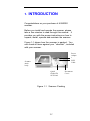
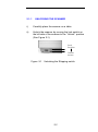
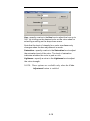
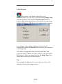
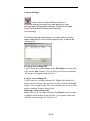
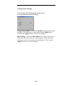
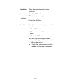
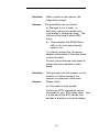
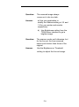
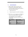
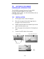
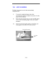
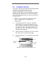
AV8000S
Flatbed/ ADF Color Document
Scanner
User's Manual
( D/N: 250-0351-0 Rev. 2.0 )
FCC Radio Frequency Interference Statement
This equipment has been tested and found to
comply with the limits for a class B digital
device, pursuant to Part 15 of the FCC rules.
These limits are designed to provide reasonable
protection against harmful interference in a
residential installation. This equipment generates,
uses, and can radiate radio frequency energy and, if
not installed and used in accordance with the
instruction manual, may cause harmful interference
to radio communication. However, there is no
guarantee that interference will not occur in a
particular installation. If this equipment does cause
harmful interference to radio or television reception,
which can be determined by turning the equipment
off and on, the user is encouraged to try to correct
the interference by one or more of the following
measures:
* Reorient or relocate the receiving antenna.
* Increase the separation between the equipment and
receiver.
* Connect the equipment into an outlet on a circuit
different from that to which the receiver is connected.
* Consult the dealer or an experienced radio/TV
technician for help.
CAUTION: Any changes or modifications not expressly
approved by the manufacture of this device could void the
user's authority to operate the equipment.
ii
Safety
Regulation
UL, C-UL, TUV/GS,CB certificate
EMI
Regulation
FCC Part 15 Subchapter J Class B
DOC Class B (Canada)
CE, VCCI, C-TICK, BSMI
iii
Wichtige Sicherheitshinweise
1.
Bitte lesen Sie diese Hinweis sorgfältig durch.
2.
Heben Sie diese Anleitung für den späteren Gebrauch auf.
3.
Das Gerät ist vor Feuchtigkeit zu schützen.
4.
Bei der Aufstellung des Gerätes ist auf sicheren Stand zu
achten. Ein Kippen oder Fallen könnte Beschädigungen
hervorrufen.
5.
Beachten Sie beim Anschluß an das Stronmnetz die
Anschlußwerte.
6.
Alle Hinweise und Warnungen, die sich am Gerät befinden,
sind zu beachten.
7.
Wird das Gerät über einen längeren Zeitraum nicht benutzt,
sollten Sie es vom Stromnetz trennen. Somit wird im Falle
einer Ü berspannung eine Beschädigung vermiden.
8.
Ö ffnen Sie niemals das Gerät. Das Gerät dart aus Gründen
der elektrischen Sicherheit nur von authorisiertem
Servicepersonal geöffnet werden.
9.
Wenn folgende Situationen auftreten ist das Gerät vom
Stromnetz zu trennen und von einer qualifizierten Servicestelle
zu Ü berprüfung.:
a)
Flüssigkeit ist in das Gerät eingedrungen.
b)
Das Gerät war Feuchtigkeit ausgesetzt.
c)
Wenn das Gerät nicht der Bedienungsanleitung
entsprechend funktioniert oder Sie mit Hilfe dieser
Anleitung keine Verbesserung erzielen.
d) Das Gerät ist gefflen und/odor das Gehäuse ist
beschädigt.
e) Wenn das Gerät deutliche Anzeichen eines Defektes
aufweist.
iv
Table of Contents
1.
INTRODUCTION ............................................................. 1-1
2.
INSTALLATION .............................................................. 2-1
2.1
SHIPPING SWITCH .....................................................2-1
2.1.1
unlocking the scanner ................................... 2-2
2.1.2
locking the Shipping switch ......................... 2-3
2.2
SCSI INTERFACE DEVICE ID....................................2-3
2.3
SETTING SCSI TERMINATOR AND SYNC .............2-4
2.4
DOCUMENT LOADING...............................................2-6
2.5
CONNECTING THE CABLE........................................2-7
3.
SOFTWARE INSTALLATION & OPERATION ....... 3-1
3.1
SCANNING OPERATION ............................................3-1
3.1.1
Scan with the user interface: ........................ 3-1
4.
USING THE BUTTONS ................................................... 4-1
4.1
4.2
5.
CUSTOMIZING YOUR BUTTON SETTINGS ..............4-1
USING THE SCAN BUTTON ......................................4-4
USER INTERFACE........................................................... 5-1
5.1
5.2
5.3
5.4
5.5
5.6
5.7
5.8
5.9
5.10
5.11
5.12
5.13
SCAN METHOD...........................................................5-1
DETERMINING YOUR RESOLUTION ........................5-2
SELECTING A PROPER IMAGE TYPE .......................5-4
ENHANCING YOUR IMAGE ........................................5-8
CONTRAST ..................................................................5-9
INVERT IMAGE .........................................................5-10
M IRROR .....................................................................5-11
PREVIEW A UTO-A REA ...........................................5-12
PAPER SIZE/UNITS..................................................5-12
DESCREEN .................................................................5-13
SHARPEN...................................................................5-13
COLOR A DJUSTMENT .............................................5-14
A UTO LEVEL ............................................................5-14
vi
5.14
5.15
6.
MAINTAINENCE.............................................................. 6-1
6.1
6.2
7.
A DVANCED SETTINGS ............................................5-14
M ISCELLANEOUS.....................................................5-22
CLEANING THE ADF.................................................6-1
CLEANING THE GLASS ..............................................6-1
TROUBLE SHOOTING................................................... 7-1
7.1
7.2
QUESTION AND A NSWER.........................................7-1
ERROR M ESSAGES ......................................................7-6
8.
TECHNICAL SERVICE................................................... 8-1
9.
SPECIFICATION.............................................................. 9-1
10.
AUTOMATIC DOCUMENT FEEDER(ADF)
INTRODUCTION ....................................................................10-1
10.1
10.2
10.3
10.4
INSTALLATION ........................................................10-1
ADF SCANNING.....................................................10-2
CLEANING THE ADF...............................................10-3
REPLACING ADF FEEDING M ODULE...................10-4
vii
1.
INTRODUCTION
Congratulations on your purchase of AV8000S
scanner.
Before you install and operate the scanner, please
take a few minutes to read through this manual. It
provides you with the proper instructions on how to
unpack, install, operate and maintain the scanner.
Figure 1-1 shows how the scanner is packed. You
can check all items against your “checklist”, included
with your scanner.
Power
Adapte
r
SCSI
Cable
Scanner
main
body
Quick
Guide,CD/
SCSI card
Figure 1-1 Scanner Packing
1-1
Document
Cover
2.
INSTALLATION
Please unpack the scanner carefully, and check
the contents against the checklist. If any items are
missing or damaged, please contact your authorized
local dealer immediately.
Precautions
•
Keep the scanner out of direct sunlight. Direct
exposure to the sun or excessive heat may
cause damage to the unit.
•
Do not install the scanner in a humid or dusty place.
•
Be sure to use the proper AC power source.
•
Place the scanner securely on an even, flat surface.
Tilted or uneven surfaces may cause mechanical or
paper-feeding problems.
•
Retain the scanner box and packing materials for
shipping purposes.
•
Use only the AC adapter ,ADP-50ZB made by Delta
Electronics,Inc. ,included with the machine.
2.1
SHIPPING SWITCH
The scanner has a shipping switch that locks the carrier
mechanism for transportation purposes. This switch
must be unlocked before using the scanner.
Before proceeding, turn the power off, disconnect all
cables and follow the instructions below to unlock the
shipping switch.
2-1
2.1.1
UNLOCKING THE SCANNER
i).
Carefully place the scanner on a table.
ii).
Unlock the scanner by moving the lock switch on
the left side of the scanner to the “Unlock” position
(See Figure 2-1).
Lock
Position
Unlock
Positio
Figure 2-1
Unlocking the Shipping switch
2-2
2.1.2
LOCKING THE SHIPPING SWITCH
Whenever you need to move the scanner to a new
location it is advisable to lock the shipping switch to
avoid causing damage to the scanners’ internal
mechanism. Please follow the instructions below to lock
the shipping switch.
1).
Turn off the scanner.
2).
Lift the Document cover to reveal the flatbed glass
and scanning unit.
3).
Turn on the scanner.
4).
Turn off the scanner again while the scanning unit
moved to the end for a few seconds.
5).
Lock your scanner by moving the lock switch on
the left side of the scanner to the "Lock position".
2.2
SCSI INTERFACE DEVICE ID
When you have several devices on a SCSI chain, you
may need to adjust the SCSI ID selector setting located
on the back of the scanner. This setting assigns a
specific "device ID" to the scanner. If the assignment
conflicts with an existing SCSI device, please select a
new ID. (See Figure 2-2)
Note: The factory setting for scanner is ID 6. Usually, ID
0 is assigned to an internal hard disk drive, and ID 7, ID
8 ,and ID 9 are not in actual use.
Using a suitable tool, turn the selector switch until the
arrow points to the desired ID number.
2-3
2.3
SETTING SCSI TERMINATOR AND
SYNC
The scanner is equipped with a built-in terminator
switch on the rear of the scanner. (See Figure 2-2/23).Turn the terminator switch on if the scanner is to be
connected to the computer as the only or the last SCSI
device. Turn the terminator switch off if the scanner is to
be located between the computer and the other SCSI
device.
The scanner is also equipped with a built-in SYNC
switch on the rear of the scanner. (See Figure 2-2) .The
factory default setting is ON. Turn the SYNC switch off if
the SCSI card connected to your computer is not
compatible with AV8000S or your computer can not find
the AV8000S.
SCSI Connector
ADF Connector
SCSI ID Selector
ON OFF
SCSI SYNC
Figure
ON OFF
Terminator
2-2 Adjusting the SCSI ID/Terminator/SYNC
settings
2-4
scanner
Host PC
SCSI Device
Term.
Term.
(Terminator Off)
scanner
Host PC
Term.
(Terminator On)
Figure
2-2 Terminator ON/OFF
2-5
2.4
i).
DOCUMENT LOADING
Place the document to be scanned onto the
document glass face down.
ii).
Position the document so that the upper-right
corner is aligned with the reference mark.
Reference Mark
Document Cover
Document
Figure 2-5 Loading Document
2-6
2.5
i).
CONNECTING THE CABLE
Turning the Power Off
Follow the following picture to connect the power cable.
Depress the side marked “0” to turn the power off.
ii).
Turning the Power On
Depress the side marked “I” to turn the power on.
The POWER LED will light. If not, please check the
power source.
iii)
SCSI Card Connector
There are two SCSI connectors available. One is for
connecting to your PC and the other is to connect to the
scanner. Follow the following picture to connect the
SCSI cables.
To SCSI
connector
To
Power
2-7
3.
SOFTWARE INSTALLATION & OPERATION
To run the scanner at rated speed recommended , you
must have the following minimum requirements:
v
IBM compatible PC , Pentium 3 or later;
v
Microsoft Windows
v
One SCSI card installed on your computer;
v
200M bytes of available hard disk space for
installation;
v
128M bytes of RAM (256M bytes or higher
recommended);
v
A video graphics array (VGA) monitor;
v
A Microsoft Windows-compatible pointing device
(e.g.,
the mouse);
v
A CD-ROM drive.
Scanner driver Installation :
1.
2.
Start Microsoft Windows
Insert the scanner bundled CD to your CD-ROM
drive.
3.
Press the Start button and choose RUN. Type
d:\driver\setup.exe (d means the letter indicating
your current your CD-ROM drive). Choose O.K.
Follow the subsequent instructions on the
screen to complete the driver installation.
4.
3-1
3.1
SCANNING OPERATION
There are two methods to perform scanning operation:
Scanning with the user interface and Pressing the
Scan button on the front panel.
3.1.1
SCAN WITH THE USER INTERFACE:
1.
Open your image application.
2.
Pull down the File menu and choose Select Source.
If the Select Source command is not available on
the File menu, see your application’s user’s guide
to determine how the TWAIN link is used.
A dialog box with a list of scanning sources
appears.
3.
Select Avision Scanner/32Vx.xx.
You need to select the source only once, unless
you want to choose another scanner.
4.
Place the document to be scanned in the ADF or on
the flatbed glass platen.
5.
Pull down the File menu and choose Acquire.
A dialog box containing scanning features appears.
3-1
6.
Select the scanning method you want to
use on the Scan Method drop-down menu.
7.
Select the mode you want to use for your scans on
the Image Type drop-down menu.
8.
Select a scanning resolution on the Resolution
drop-down menu.
9.
Select the settings for the scanning features (e.g.,
Sharpen, Descreen, etc.) that you want to use.
10. Click on the Preview or Scan button to preview or
scan your document(s).
3-2
4.
USING THE BUTTONS
The following chapter applies only to PC users.
4.1
CUSTOMIZING YOUR BUTTON
SETTINGS
After you have successfully installed the scanner driver on
your computer, please first customize your button settings to
use the buttons properly.
To Customize your Button Preferences,
1.
Start your Button program by clicking
Start>Programs>Scanner Software>Button
Manager. The Button Manager icon appears at
the lower-right corner.
Button Manager icon
2.
3.
Click “Preferences” to prompt the Preferences
dialog.
Please see next page on how to customize your
4-1
preferences.
4-2
1.
Image Type: Choose a proper image type.
2.
Scan Size: Choose your scan size from
Letter, A4, or Business Card.
3.
Resolution: Choose a proper resolution from 100
dpi to 1200 dpi.
4.
Image Format: Choose from BMP. PCX, TIFF, or
JPEG.
5.
Image Editor: Choose your favorite image editing
application.
4-3
4.2
USING THE SCAN BUTTON
Scan Button
1. Press the Scan button.
Scan and load your scanned image to your image
editing software application.
2. The status bar will display to indicate the progress
of your task.
4-4
5. USER INTERFACE
5.1
SCAN METHOD
Select how you want to scan on the Scan
Method drop-down menu.
Flatbed— use this setting if you are using the flatbed to
scan one page at a time.
The following options available for the ADF
document cover:
Simplex/One-page— use this setting if you are using
the automatic document feeder (ADF) to scan a singlepage document at a time.
Simplex /Multi-page— use this setting if you are using
the automatic document feeder (ADF) to scan batches of
single-page document at a time.
5-1
5.2
DETERMINING YOUR RESOLUTION
A good control of the resolution results a
satisfactory detail of an image that scans. The
resolution is measured by dots per inch(dpi). Normally,
the greater the dpi number, the higher the resolution and
the image file size.
Be aware that the greater resolution takes more time,
memory and disk space, therefore, up to a certain
degree of dpi, the resolution will not visually be improved,
on the contrary, it makes your files more unmanageable.
Resolution: 50 dpi
Resolution: 100 dpi
5-2
Tips:
1. For your information, an A4 size color image
scanned at 300 dpi at True Color mode consumes
approximately 25 MB of disk space. A higher
resolution (usually means over 600 dpi) is
recommended only when you need to scan a small
area at True Color mode.
2. You can also refer to the following table to choose a
proper resolution while applying your image to other
application.
Image
Scanner Settings
Type
Application
File, Fax, E-mail Your
LineArt
Document
View, Copy, Edit Your True Color
Color Picture
OCR* Your Document
LineArt
Resolution
(dpi)
200
100
300
*OCR: Stands for Optical Character Recognition, the
process to convert an image to a text format.
5-3
5.3
SELECTING A PROPER IMAGE
TYPE
Select image type through the mode from
the scanner user interface for your own purpose.
Each image type is described as follows:
Line art(Black and White)
LineArt presents the image in black and white only and
there are no intermediate shades of gray in between.
That means each pixel of the image is 100% black or
100% white.
LineArt is the best choice of image type
if you want to scan text, pen or ink drawing. Since only
1-bit of black or white information is required for each
pixel*, the disk space required for saving lineArt image
is only about 1/24 of that required to save 24-bit true
color images.
Lineart Image
*Pixel: A combination of two words: picture and element,
a pixel is a single dot on a computer display or in a
digital image.
5-4
Halftone
In addition to the black and white display,
Halftone simulates gray scale by using
different size of dots. Particularly when you
view the image at a certain distance, it looks very
closely like a gray image yet it consumes the least
disk space. Halftone is the picture that we usually
see in newspapers or magazines. Since Halftone is
one type of black and white image, the disk space
required to save a halftone image is 1/24 of that
required to save a 24-bit true color image.
Halftone Image
5-5
8-Bit Gray
A single-channel image consists of at least 256
shades of gray. An 8-bit scanner produces a grayscale image
with 1024 shades of gray between pure black and pure white.
Choose this option if you are scanning black-and-white
photographs.
With 8 bits of color information per pixel, the file size of an
image is eight times larger than a Black and White image and
1/3 the size of a 24-Bit Color image.
Gray Image
5-6
8-Bit Color
an 8-Bit Color image provides 256 color hues in the image.
The file size of a 256 color image is 1/3 the size of a 24Bit Color image.
8-Bit
Color Image
24-Bit Color
A 24-Bit Color image consists of three 8-bit color channels.
The red, green, and blue channels are mixed together to create
a combination of one billion colors which give a more true-tolife quality to the image. Choose 24-Bit Color if you are
scanning color photos.
24-Bit
5-7
Color Image
5.4
ENHANCING YOUR IMAGE
Brightness:
Adjusts the lightness or
darkness of an image.
The higher the value, the brighter the image.
Increase your Brightness
5-8
5.5
CONTRAST
Adjusts the range between the darkest
and the lightest shades in the image.
The higher the contrast, the bigger the
different gray scales.
Increase your
Contrast
5-9
5.6
INVERT IMAGE
The invert command reverses the brightness
and the color in the image. For color images, each
pixel will be changed into its complementary color at the
command of Invert.
Original
After Invert
5-10
5.7
MIRROR
Click on the Mirror button to reverse the
image (create a mirror image).
Mirror function is off
Mirror function is on
5-11
5.8
PREVIEW AUTO-AREA
Clicking on the Preview Auto-Area button
automatically crops the preview scan area to the previewed
document. This will then be the cropping area for all of the
scanned documents.
5.9
PAPER SIZE/UNITS
Select a size on the Paper Size list of frequently
used scan sizes.
Card- 4 x 2.5 in
Photo- 5 x 3.5 in
Photo- 3.5 x 5 in
Photo- 6 x 4 in
Photo- 4 x 6 in
B5- 18.2 x 25.7 cm
A5- 14.8 x 21.0 cm
A4- 21.0 x 29.7 cm
Letter- 8.5 x 11 in
Legal- 8.5 x 14 in
A3- 29.7 x 42 cm
Scanner Maximum
The Units button indicates the measuring system
that is in use(Inch, Cm, or Pixel).
5-12
5.10
DESCREEN
Click on the Descreen button to access a drop-down
menu that allows you to specify the type of document you are
scanning in order to eliminate the moiré pattern* commonly
found in printed matter. You can specify Newspaper,
Magazine, or Catalog.
Before Descreen
After Descreen
*Moiré pattern— an undesirable pattern resulting from the
incorrect screen angle of the overprinting halftone.
5.11
SHARPEN
Click on the Sharpen button to access a drop-down
menu that allows you to specify a level to sharpen the
scanned image. You can specify a Sharpen setting of Light,
More, Heavy, or Extra Heavy.
5-13
5.12
COLOR ADJUSTMENT
Click on the Color Adjustment button to enable the
button for the Hue, Saturation, and Lightness feature.
NOTE: The Advanced Settings button must be enabled in
order to use the Hue
Saturation, and Lightness feature.
5.13
AUTO LEVEL
Click on the Auto Level button to add shadow to
reveal more details in an image.
5.14
ADVANCED SETTINGS
Click on the Advanced Settings button to view the
advanced settings buttons for Highlight / Shadow, Curves,
Color Balance, Hue / Saturation / Lightness, Color
Drop-out, and Custom Settings (six buttons on the right side
of the TWAIN dialog box).
Highlight / Shadow
5-14
This feature is available when 8-Bit Gray, 8-Bit Color,
or 24-Bit Color is selected on the Image Type drop-down
menu. Highlight refers the lightest point in a scanned
image; shadow refers the darkest point.
Click on the Highlight / Shadow button to access the
Highlight / Shadow Levels dialog box. You can type values in
the text boxes or you can place the mouse cursor over the
line, click the right mouse button, and drag the line to specify
the values you want.
Use the Highlight and Shadow settings together to extend the
range of color and reveal more details in a color image.
5-15
Curves
When you select the Curves button, a dialog box
appears that allows you to adjust the midtone of the image
without losing details in the lightest and darkest areas.
Select the Curve or Line button, depending on if you want a
curved or an angled setting. Place the mouse cursor over
the line, click the right mouse button, and drag the line to set
the curve you want.
5-16
Color Balance
When you select the Color Balance button, a dialog
box appears that allows you to adjust the color of the image
so that it comes close to that of the original.
The default parameters are used to adjust the image. You
can type values in the Color Levels text boxes or you can
drag the sliding arrow under the color.
Hue /Saturation /Lightness
Click on this button to adjust the hue, saturation, and
lightness of an image. This button is enabled when the
Color Adjustment button is selected. You can type values in
the text boxes or you can drag the sliding arrow under the
each item.
5-17
Hue— specify a value in the Hue box to adjust the hue up to
360° by clicking on the desired color on the color wheel or
selecting a setting on the drop-down menu.
Note that the level of intensity for a color simultaneously
changes when the hue a djustment is made.
Saturation— specify a value in the Saturation box to adjust
the saturation level of the color. The level of saturation
indicates whether the color is pale or rich.
Lightness— specify a value in the Lightness box to adjust
the color strength.
NOTE: These options are available only when the Color
Adjustment button is enabled.
5-18
Color Drop-out
This feature is available when Black and
White, Halftone, or 8-Bit Gray is selected on the Image Type
drop-down menu. Click on the Color Drop-out button to
access a dialog box that allows you to choose to remove the
R (Red), G (Green), or B (Blue) color channel while scanning.
For example, if your image contains red text or a red
background, choose R channel (red) to remove the red text or
red background.
This feature is applicable only for black-and-white and
grayscale images. Make sure that you have selected a blackand-white or grayscale image type (on the Image Type dropdown menu) when you use this option.
Tip
Increasing the brightness after removing one of the color
channels will make the image clearer.
5-19
Custom Settings
Click on the Custom Settings button to
access a dialog box where you can save your scan
settings and configuration settings. There are two tabs:
Scan Settings and Configuration Settings.
Scan Settings
The Scan Settings tab allows you to save your scanning
feature settings in a file, load an existing file, or delete an
existing file.
Saving a scan settings file
Type a name for your settings in the File Name text box and
click on the Save button. Your settings will be saved and the
file name will appear in the list box.
Using a scan settings file
You can use an existing settings file. Right-click on the file
name for the settings you want to use and click on the Load
button. The settings in the file will automatically be specified
in the scanning features dialog box.
Deleting a scan settings file
Right-click on a file name and press the Delete button on the
computer keyboard to delete the file. You cannot delete the
default scan settings file default.av2.
5-20
Configuration Settings
The Configuration Settings tab allows you to
customize some special settings.
Energy Saving Mode— check the Enable box to enable energy
savings. You can specify a time delay in the Minutes box.
Click on the Apply button to save the changes.
Hint Setting— check the Show Hints box if you want to have
flags that show the name of an item appear when you place
the mouse cursor on an item in the dialog box. Click on the
Apply button to save the changes.
5-21
5.15
MISCELLANEOUS
Width : Shows the current image width.
Height: Shows the current image height.
Size: Shows the current file size of the scanned image.
Lock scale
Click on this button to fix the output width and height
despite the selected scan size.
The scale value automatically changes when you apply this
option and simultaneously resize the selected area.
Information
Click on the Information button to access a window
that gives you information about the scanner and driver.
5-22
Preview: Click on the Preview button to scan a document so
you can review the scanned image. This allows you to
specify an area to be scanned and any scanning
feature settings to be used for future scans. When a scanning
feature is changed and applied, the Preview image is updated
for a real-time view of the change.
You can define the area to be scanned by dragging the cursor
lines with the mouse.
Zoom view: Click on the Zoom view button to preview a
selected area.
Scan: Click on the Scan button to scan the area with the
specified parameters.
You can define the area to be scanned by dragging the cursor
lines with the mouse.
Exit: Click on the Exit button to cancel the current job.
5-23
6.
MAINTAINENCE
6.1 CLEANING THE ADF
The scanner is designed to be maintenance free.
However, it still needs to be cleaned occasionally to
ensure optimum image quality and performance.
6.2
CLEANING THE GLASS
The procedures:
i).
Soak a cotton swab with some isoprophy alcohol
(95%).
ii).
Open the ADF unit and document cover as shown
in Figure 6-2. Wipe the glass of flatbed area by
moving the swab from side to side.
Glass
Figure 6-2 The Cleaning Area
6-1
7.
TROUBLE SHOOTING
The scanner will automatically perform a simple
self-test each time it is turned on. This will help
spot major system errors in the scanner itself.
When the test is initiated, the READY/Error LED is
flashing. When the test is completed, if no error occurs,
the READY/Error LED is steadily on.
If you have problems with the operation of your scanner,
please check the following troubleshooting hints.
7.1
QUESTION AND ANSWER
Question:
The READY/Error LED indicates that
the scanner is ready, but the scanner
does not respond to the scan
command from the host computer.
Answer:
a) Please check if the signal cable is
firmly seated, and invoke the scan
command again. If there is still no
response, please reset the scanner
by turning it off and then on again,
and reboot your host computer as
well.
b) Check if the driver is correctly
installed.
7-1
Question:
Paper becomes jammed during
scanning.
Answer: a) Open the ADF unit.
b) Pull out the jammed paper
carefully.
c) Close the ADF unit.
Question:
More than one sheet of paper were fed
into the scanner.
Answer:
a) Open ADF unit.
b) Remove the multi-fed sheets of
paper.
c) Close the ADF unit.
d) Flatten the corners and edges;
loosen the paper before reloading it
in the paper guide.
e) Check the feeding roller condition
and do the cleaning if necessary.
7-2
Question:
Answer:
Paper becomes skewed in the
scanner.
a) Check the feeding roller
condition; do the cleaning if
necessary.
b) Use the paper guide when feeding
the paper.
Question:
When I power on the scanner, it
makes noises and will not stand
ready.
Answer:
There are two possibilities:
a) You forgot to remove the shipping
switch from the scanner. Please
remove the shipping retainer first.
b) You did not place the scanner on a
flat desktop surface. This may
cause the scanner to function
improperly.
7-3
Question:
When I power on the scanner, the
lamp does not light.
Answer:
The possibilities are as follows:
a) The lamp is out of order. In
that case, contact your authorized
local dealer to change the lamp. The
life time of the lamp is about 5000
hours.
b) Check whether the READY/Error
LED on the front panel steadily
lights or not.
If it flashes orange light, the power
adapter malfunctions or the main board
is short-circuited.
Contact your authorized local dealer to
replace the power adapter or main
board.
Question:
Getting image from the scanner is not a
problem, but when scanning, the
scanner or system will often crash.
Answer:
Please check
a) If the cable is firmly seated;
b) Only two SCSI terminators can be
connected to your SCSI daisy chain. One
is at the end of the SCSI device, and
another is already in your host adapter.
7-4
Question:
The scanned image always
comes out to be too dark.
Answer:
a) Use your application to
modify the Gamma setting to 2.2 and
1.8 for your printer and monitor
respectively.
b) Use Brightness setting from the
TWAIN user interface to get a
brighter image.
Question:
The scanner works well otherwise, but
for the line art, the lines scanned
seem much thicker than those of the
original.
Answer:
Use the Brightness or Threshold
setting to adjust the line art image.
7-5
7.2
ERROR MESSAGES
1. When the Paper In/Paper Jam lamp on the
front panel turns orange steadily, paper jam
in the ADF happens. Please remove the paper by
following the procedures below.
i).
Open the ADF cover.
ii).
Remove the paper out of the ADF unit carefully.
2. When there is an error happening, the Ready/Error
lamp on the front panel flashes in orange with
various frequencies. The error messages,
corresponding to frequencies, are shown in the
following table:
Flash Frequency
2 times
5 times
Error Message
SDRAM Test Failure
Motor or Home sensor
error
Light check error
Chassis lock
6 times
7 times
7-6
8.
TECHNICAL SERVICE
Technical support for Avision scanner is provided
at Avision Technical Assistance Center (ATAC). Before
contact with ATAC, please prepare the following
information.
v
v
v
v
Scanner serial & revision number (located on the
bottom
of the scanner)
Hardware configuration (e.g., your host CPU type,
RAM size, free disk space, display card, interface
card, etc.)
The name and version of your software application
The version of your scanner driver.
Please call us at:
US and Canada Area:
Address:
Telephone
number:
Fax number:
Web Site:
E-mail:
Other Area:
Address:
Telephone
number:
Fax number:
Web Site:
Email:
Avision Labs., Inc.
6815 Mowry Ave. Newark CA 94560,
USA
+1 (510) 739-2369
+1 (510) 739-6060
http://www.avision.com
[email protected]
Avision Inc.
No.20, Creation Road I, Science-Based
Industrial Park, Hsinchu,
Taiwan, R.O.C.
+886 (3) 578-2388
+886 (3) 577-7017
http://www.avision.com
[email protected]
8-1
9.
SPECIFICATION
Model: AV8000S
Item
SPEC.
Optical Resolution
Max. Scan Area
Physical Dimension
600 x 1200 dpi
11.8” x 17”
589 x 428 x 135mm
(width) (depth) (height)
[316 mm(height) with ADF]
7.6Kg
2 x SCSI (50 Pin Half pitch)
Power Adapter, 24V DC
Net Weight
Interface
Power Supply
ADF Module(Optional):
ADF Scan Speed
Linear A4,300dpi: 35PPM
Gray A4,300dpi: 25PPM
Color A4,300dpi: 9PPM
50 sheets
3.7 Kg
ADF Paper Tray Capacity:
ADF Net Weight
9-1
10.
AUTOMATIC DOCUMENT
FEEDER(ADF) INTRODUCTION
The AV8000S Automatic Document Feeder (ADF)
is a very convenient addition to your current
AV8000S. With the ADF, you can automatically scan up
to 35 pages per minute.
10.1
INSTALLATION
i).
Lift the paper chute to about 45 degrees.
ii).
Move the two paper-chute plastic legs down to
the grips on the document cover.
iii).
Slightly snag the paper chute plastic legs into the
grips on the document cover.
iv).
Move the paper chute extension to the length you
want.
v).
Connect the ADF cable to the scanner.
Paper Chute
Paper Chute Extension
Plastic leg
ADF
Cable
10-1
10.2
ADF SCANNING
Multiple documents can be fed automatically
using the ADF.
i).
To prevent occasional paper jam when
automatically feeding multiple documents, fan the
paper before loading.
ii).
Place the documents face-up onto the ADF paper
chute, with the leading edge in the auto feeder
entrance.
iii).
Adjust the left and right guides so that they are
snug against the sides of the documents.
Faced-up Document
Left/right
guide
10-2
10.3
CLEANING THE ADF
From time to time the pad assembly and feeding rollers
may become contaminated with ink, toner
particles or paper dust. In this case the
scanner may not feed documents smoothly or several
documents may feed at once. If this occurs please
follow the cleaning procedures to return your scanner to
its original state.
i).
Moisten a cotton swab with isoprophyl alcohol
(95%). (Cleaner kits are available from
PictureVision.)
ii).
Carefully open the ADF to the left . Wipe the
feeding rollers by moving the swab from side to
side. Rotate the rollers forward with your finger
and repeat the above cleaning procedures until
the rollers are clean. Be careful not to snag or
damage the pick springs.
iii).
Wipe the pad in the direction from top to bottom.
Be careful not to hook the pick springs.
iv).
Close the ADF unit. Your scanner is now ready
for use.
ADF
ADF feed
Feeding
module
Rolle
Opening the ADF unit and Document Cover
10-3
10.4 REPLACING ADF FEEDING
MODULE
After scanning approximately 20,000 pages
through the ADF, the separation pad may be worn out
and you may experience problems with document
feeding. In this case, it is highly recommended to
replace the pad module with a new one. For ordering
the pad module, please consult your nearest dealer and
follow the procedure below to replace it.
Disassembling Procedure
1.
Open the ADF cover.
2.
Remove the ADF snap-in pad module by pulling out
the upper part of the pad clamp as shown in Figure
6-3.
Upper Part of ADF Pad Clamp
Removing the pad
10-4