1
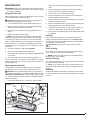
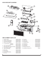
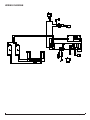
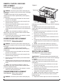
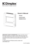
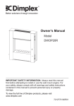
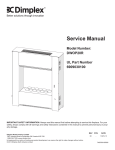
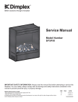
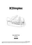
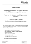
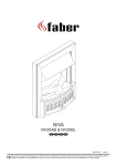
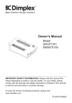
Service Manual
Model
Part Number
DFI400L6909050241
DFI400R6909050242
DFI600L6909050261
IMPORTANT SAFETY INFORMATION: Always read this manual first before attempting to service this cassette. For your
safety, always comply with all warnings and safety instructions contained in this manual to prevent personal injury or property damage.
Dimplex North America Limited
1367 Industrial Road Cambridge ON Canada N1R 7G8
1-888-346-7539 www.dimplex.com
In keeping with our policy of continuous product development, we reserve the right to make changes without notice.
© 2013 Dimplex North America Limited
REV
PCN
DATE
00
-
1-NOV-13
7400770000R00
TABLE OF CONTENTS
Operation. . . . . . . . . . . . . . . . . . . . . . . . . . . . . . . . . . . . . . . . . . . . . . . . . . . . . . . . . . . 3
Maintenance. . . . . . . . . . . . . . . . . . . . . . . . . . . . . . . . . . . . . . . . . . . . . . . . . . . . . . . . . 4
Exploded Parts Diagram. . . . . . . . . . . . . . . . . . . . . . . . . . . . . . . . . . . . . . . . . . . . . . . 5
Replacement Parts List. . . . . . . . . . . . . . . . . . . . . . . . . . . . . . . . . . . . . . . . . . . . . . . . 5
Wiring Diagram . . . . . . . . . . . . . . . . . . . . . . . . . . . . . . . . . . . . . . . . . . . . . . . . . . . . . . 6
Remote Control Receiver Replacement . . . . . . . . . . . . . . . . . . . . . . . . . . . . . . . . . . 7
Power Board Replacement . . . . . . . . . . . . . . . . . . . . . . . . . . . . . . . . . . . . . . . . . . . . 7
Switch Replacement . . . . . . . . . . . . . . . . . . . . . . . . . . . . . . . . . . . . . . . . . . . . . . . . . . 7
Potentiometer Replacement . . . . . . . . . . . . . . . . . . . . . . . . . . . . . . . . . . . . . . . . . . . 8
Power Cord Replacement. . . . . . . . . . . . . . . . . . . . . . . . . . . . . . . . . . . . . . . . . . . . . . 8
Light Assembly Replacement . . . . . . . . . . . . . . . . . . . . . . . . . . . . . . . . . . . . . . . . . . 8
Fan Assembly Replacement. . . . . . . . . . . . . . . . . . . . . . . . . . . . . . . . . . . . . . . . . . . . 8
Troubleshooting Guide. . . . . . . . . . . . . . . . . . . . . . . . . . . . . . . . . . . . . . . . . . . . . . . 10
Always use a qualified technician or service agency to repair this cassette.
! NOTE: Procedures and techniques that are considered important enough to emphasize.
CAUTION: Procedures and techniques which, if not carefully followed, will result in damage to the equipment.
WARNING: Procedures and techniques which, if not carefully followed, will expose the user to the risk of fire, serious
injury, or death.
2www.dimplex.com
OPERATION
Figure 2
Figure 1
C
B
A
Standby
Button
On
Button
Remote Control
Sensor
Battery Cover
! NOTE: Always ensure that the appliance is in an upright
position before operating the unit.
! NOTE: When the cassette is used in an environment
where background noise is very low, it may be possible to
hear a sound which is related to the operation of the flame
effect. This is normal and should not be a cause for concern.
! NOTE: Always ensure that the appliance is in a level
position.
The manual controls for the cassette are located on the top
of the unit, below the control cover. (Figure 1)
A. On/Off Switch
Supplies power to the cassette.
B. Mode Selector Switch
Press once to turn on the flame effect. This will be indicated
by an audible “beep”. Although the lights turn on immediately it will take 30 seconds before the flame effect starts.
Press
to put fire in to standby mode. This will be indicated by one “beep”.
C. Flame Intensity Control
Adjusts the intensity of the flame effect when the cassette
has been activated.
Turning the control knob clockwise to decrease the intensity of the flame effect. Turning the control knob counterclockwise will increase the flame effect.
! NOTE: Give the flame generator some time to react to
changes you may make on the flame control knob.
! NOTE: When the water tank is empty the unit will turn
off after 30 seconds. See instructions under Maintenance
Section for refilling tank. When this procedure is complete,
the main lamps will illuminate but it will take 30 seconds
before the flames return.
Remote Control
The On/Off Switch must be in the ‘ON’ ( I ) position in order
for the remote control to operate. (Figure 2)
! NOTE: To operate correctly, the remote control must be
pointed towards the remote control sensor.
To operate, push the ON button to turn fireplace on, push
the Standby button to turn the fireplace off.
Battery Replacement
To replace the battery:
1. Slide battery cover open on the remote control (Figure
2).
2. Install two 1.5 Volt (AAA) batteries in the battery holder.
3. Close the battery cover.
Battery must be recycled or disposed of properly.
Check with your Local Authority or Retailer for recycling advice in your area.
3
MAINTENANCE
W
ARNING: Disconnect power before attempting any maintenance or cleaning to reduce the risk of fire, electric shock
or damage to persons.
Filling the water tank
When the water tank is empty, the flame shuts off and you will
hear 2 audible beeps, follow these steps.
CAUTION: Allow at least five minutes for components to
cool before disassembling the unit to refill.
1. Turn the On/Off switch to the off position (0) (Figure 1)
2. Gently remove the media tray and media (if applicable)
and place them carefully on the ground.
3. Remove the refill container by lifting upwards and outwards.
4. Refill the container with tap water.
! NOTE: Normal tap water can be used in the Optimyst®
as long as the tap water is not considered to be hard water.
In the event your tap water is hard, you may use softened
water or distilled water with 1/8 tsp of salt (0.5 mL) added to
the water reservoir. (The addition of additional salt should
only be when you notice that the unit is not producing mist as
expected.)
cable), tray and water tank (Figure 3) and lift out the top
cover.
2. View the lamps from a distance in front of the fire and
observe which lamp needs to be changed.
3. Turn the unit off, and unplug the cassette.
4. Leave the appliance for 5 minutes to allow the lamps to
cool down before removing them.
5. Remove the water tank and top cover (Figure 3) by lifting
upwards and place in a sink.
6. Remove the defective bulb, by gently lifting vertically and
disengaging the pins from the lamp holder.
7. Carefully insert the two pins of the new bulb into the two
holes in the lamp holder. Push lamp firmly in place.
8. Gently place the media tray and media (if applicable) back
into position.
Cleaning
It is recommended that all of the components that contain
water are cleaned with soap and water on a biweekly basis.
A small brush has been included to assist in cleaning difficult
items/areas, i.e. the transducer.
CAUTION: Do not put plastic components in the dishwasher.
5. Screw the cap back on, do not overtighten.
Filter Cleaning
6. Return the refill container to the water tank.
The air filter can be removed and gently rinsed with water to
clean and dried on a towel before reinstalling.
7. Gently place the media tray and media (if applicable) back
into position.
8. Turn the On/Off switch to the off position (I). (Figure 1)
If you do not intend on using the unit for longer than 2 weeks,
empty and drain the unit of water, and dry all of the water containing components.
Replacing the Light bulbs
If a large amount of the flame appears grey or colourless it
may be that one or more of the light bulbs have burnt out.
CAUTION: Allow at least twenty minutes for light bulbs to
cool before touching bulbs to avoid accidental burning of skin.
Light bulb requirement: 45W, 12VAC halogen bulbs type MR
16. Contact Dimplex Technical Service at 1-888-346-7539 for
replacement bulbs.
! NOTE: Replace the filter so that the course black filter is
facing the front of the cassette.
Surface Cleaning
Use a warm damp cloth only to clean surfaces of the cassette.
Do not use abrasive cleaners.
! NOTE: If you need to move the unit ensure that all of the
components that contain water have been emptied before relocating.
Servicing
Except for installation and cleaning described in this manual,
an authorized service representative should perform any other
servicing.
1. Leaving the flame effect on, remove the media (if appli-
Figure 3
Top
Cover
Emitter
Retaining
Tab
Fan
Housing
Transducer
Wire Slot
Water Tank
4www.dimplex.com
EXPLODED PARTS DIAGRAM
5
7
9
8
3
10
4
13
14
22
12
11
6
19
1
21
17
16
18
15
20
2
REPLACEMENT PARTS LIST
1.
2.
3.
4.
5.
Remote Control. . . . . . . . . . . . . . . . . . .
Remote Control Receiver. . . . . . . . . . .
Rock Media (DFI400RH). . . . . . . . . . .
Media Tray (DFI400RH). . . . . . . . . . . .
Log Set Assembly - DFI400LH. . . . . . .
- DFI600LH. . . . . . .
6. Light Holder Assembly . . . . . . . . . . . . .
7. Removable Refill Container with Cap.
8. Cap for Refill Container. . . . . . . . . . . .
9. Top Cover Assembly. . . . . . . . . . . . . . .
10. Water Tank . . . . . . . . . . . . . . . . . . . . .
11. Fan Assembly . . . . . . . . . . . . . . . . . . .
12. Fan Housing Assembly . . . . . . . . . . . .
13. Fan Filter. . . . . . . . . . . . . . . . . . . . . . .
9600800100RP
9600580200RP
9600650100RP
9600710100RP
9600720100RP
9600730100RP
9600610200RP
0441440100RP
0441440300RP
9600670100RP
0441380100RP
5300300100RP
9600540100RP
8600300100RP
14. Transducer . . . . . . . . . . . . . . . . . . . . . . 3800040100RP
15. Power Cord . . . . . . . . . . . . . . . . . . . . . 9600740100RP
16. On/Off Switch . . . . . . . . . . . . . . . . . . . . 9600383500RP
17. 3-Position Switch . . . . . . . . . . . . . . . . . 9600383600RP
18. Transformers. . . . . . . . . . . . . . . . . . . . 9600690100RP
19. Potentiometer. . . . . . . . . . . . . . . . . . . . 9600640100RP
20. Power Board . . . . . . . . . . . . . . . . . . . . 9600590100RP
21. IR Receiver with Lens . . . . . . . . . . . . . 9600600200RP
22. Light Bulbs (Package of 4). . . . . . . . . . . . . . . . . RB400
5
WIRING DIAGRAM
WHITE
WHITE
BLACK
MAINS
3 CORE
CABLE
DC FAN
MOTOR
TRANSDUCER
MALE JACK
6www.dimplex.com
REMOTE CONTROL RECEIVER
REPLACEMENT
Figure 4
Tools Required: Philips head screwdriver
Flat Head Screwdriver
WARNING: Disconnect power before attempting any
maintenance to reduce the risk of electric shock or damage
to persons.
! NOTE: Ensure that all of the components that
contain water have been emptied before performing any
maintenance.
1. Disconnect and remove the media from the unit and
put them in a safe place.
2. Remove the 4 screws that secure the front grill to the
cassette housing. (Figure 4)
3. Remove the 4 screws around the remote control receiver attaching it to the unit.
4. Transfer the wire connectors from the terminals on the
original board to the same location on the replacement
board.
! NOTE: Use a flat head screwdriver to gently pry
between the end of the connector and the remote control
receiver to release the wires.
5. Re-assemble the remainder of the cassette in reverse
order from the instructions above.
POWER BOARD REPLACEMENT
Tools Required: Philips head screwdriver
Flat Head Screwdriver
WARNING: Disconnect power before attempting any
maintenance to reduce the risk of electric shock or damage
to persons.
! NOTE: Ensure that all of the components that
contain water have been emptied before performing any
maintenance.
1. Disconnect and remove the media from the unit and
put them in a safe place.
2. Remove the 4 screws that secure the front grill to the
cassette housing. (Figure 4)
3. Remove the 4 screws around the power board attaching it to the unit.
4. Transfer the wire connectors from the terminals on the
original board to the same location on the replacement
board.
! NOTE: Use a flat head screwdriver to gently pry
between the end of the connector and the remote control
receiver to release the wires.
5. Re-assemble the remainder of the cassette in reverse
order from the instructions above.
TRANSFORMER REPLACEMENT
Tools Required: Philips head screwdriver
Flat Head Screwdriver
WARNING: Disconnect power before attempting any
Transformers
Power Board
Front Grille
Remote Control
Receiver
maintenance to reduce the risk of electric shock or damage
to persons.
! NOTE: Ensure that all of the components that
contain water have been emptied before performing any
maintenance.
1. Disconnect and remove the media from the unit and
put them in a safe place.
2. Remove the 4 screws that secure the front grill to the
cassette housing. (Figure 4)
3. Remove the screws that secure the transformer to the
unit.
4. Transfer the wire connectors from the terminals on the
original board to the same location on the replacement
board.
! NOTE: Use a flat head screwdriver to gently pry
between the end of the connector and the remote control
receiver to release the wires.
5. Re-assemble the remainder of the cassette in reverse
order from the instructions above.
SWITCH REPLACEMENT
Tools Required: Philips head screwdriver
Flat Head Screwdriver
WARNING: Disconnect power before attempting any
maintenance to reduce the risk of electric shock or damage
to persons.
! NOTE: Ensure that all of the components that
contain water have been emptied before performing any
maintenance.
1. Disconnect and remove the media from the unit and
put them in a safe place.
2. Remove the 4 screws that secure the front grill to the
cassette housing. (Figure 4)
3. Locate the defective switch and disconnect the wiring
connections noting their original locations.
! NOTE: A flat head screwdriver can be used to gently
pry between the end of the connector and the switch to
release the wires.
4. Depress the retainer clips on the rear of the switch and
7
push the switch out through the opening.
5. Properly orient and insert the new switch and connect
all of the wiring.
6. Re-assemble the remainder of the cassette in reverse
order from the instructions above.
Figure 5
POTENTIOMETER REPLACEMENT
Tools Required: Philips head screwdriver
Flat Head Screwdriver
3/8” (10mm) Wrench
WARNING: Disconnect power before attempting any
maintenance to reduce the risk of electric shock or damage
to persons.
! NOTE: Ensure that all of the components that
contain water have been emptied before performing any
maintenance.
1. Disconnect and remove the media from the unit and
put them in a safe place.
2. Remove the 4 screws that secure the front grill to the
cassette housing. (Figure 4)
3. Turn the unit so that the underside of the potentiometer
can be seen.
4. Loosen the securing nut, to allow the potentiometers
slide out.
5. Disconnect the wiring connections noting their original
locations.
! NOTE: A flat head screwdriver can be used to gently
pry between the end of the connector and the switch to
release the wires.
6. Slide the potentiometer back into the assembly and
tighten the securing nut.
7. Re-assemble the remainder of the cassette in reverse
order from the instructions above.
POWER CORD REPLACEMENT
Tools Required: Philips head screwdriver
Flat head screwdriver
WARNING: Disconnect power before attempting any
maintenance to reduce the risk of electric shock or damage
to persons.
! NOTE: Ensure that all of the components that
contain water have been emptied before performing any
maintenance.
1. Disconnect and remove the media from the unit and
put them in a safe place.
2. Remove the 4 screws that secure the front grill to the
cassette housing. (Figure 4)
3. Locate the cord and disconnect the wiring connections
noting their original locations.
! NOTE: A flat head screwdriver can be used to gently
pry between the end of the connector and the switch to
release the wires.
4. With needle nose pliers, grasp the cord strain relief
grommet from inside the back of the bottom panel and
push while twisting to remove.
5. Install the new cord.
6. Reassemble in the reverse order as above.
LIGHT ASSEMBLY REPLACEMENT
Tools Required: Philips head screwdriver
Flat Head Screwdriver
WARNING: Disconnect power before attempting any
maintenance to reduce the risk of electric shock or damage
to persons.
! NOTE: Ensure that all of the components that
contain water have been emptied before performing any
maintenance.
1. Disconnect and remove the media from the unit and
put them in a safe place.
2. Disassemble the sump components. (Figure 3)
3. With the unit turned upside down, remove the 2 screws
that hold the light assembly to the unit. (Figure 5)
4. Remove the light assembly and replace with the new
light assembly.
5. Reattach the wire onto the new light assembly.
6. Re-assemble the remainder of the cassette in reverse
order from the instructions above.
FAN ASSEMBLY REPLACEMENT
Fan Motor and Fan Housing
Tools Required: Philips head screwdriver
Flat Head Screwdriver
WARNING: Disconnect power before attempting any
maintenance to reduce the risk of electric shock or damage
to persons.
! NOTE: Ensure that all of the components that
contain water have been emptied before performing any
maintenance.
8www.dimplex.com
1. Disconnect and remove the media from the unit and
put them in a safe place.
2. Disassemble the sump components. (Figure 3)
3. Remove the 3 screws that hold the cover onto the fan
housing. (Figure 6)
4. Remove the fan motor out of the housing and disconnect the wiring connection located near the bottom of
the housing.
5. If replacing only the motor, attach new motor and reassemble the remainder of the cassette in revers order
from the instructions above.
• If replacing the housing, remove the 3 screws attaching
the base to the cassette. (Figure 6)
6. Attach new fan housing base to the cassette.
7. Transfer the filter from the old housing to the new housing.
8. Reinstall the fan motor and reconnect the wire.
9. Re-assemble the remainder of the cassette in reverse
order from the instructions above.
Figure 6
9
TROUBLESHOOTING GUIDE
PROBLEM
CAUSE
SOLUTION
General
Unpleasant smell when unit is
used.
Dirty or stale water.
Clean the unit as described under maintenance.
Improper operation
Refer to Operation Section
No incoming voltage from the electrical wall
socket
Check Fuse/Breaker Panel
Defective 3 Position Switch
Replace 3 Position switch
Improper operation
Refer to Operation Section
The batteries in the remote control are dead.
Install new battery into the remote control
Defective remote control
Replace Remote Control
Defective remote control receiver
Replace remote control receive
Defective IR sensor
Replace IR sensor
Switch A is in the ‘ON’ (I) position, but mode
Switch B has not been pressed.
Press Switch B once for flame effect.
Low water level.
Check the water tank is full and there is water in
the sump.
Water in unit is too cold
Allow water to warm to room temperature.
If using distilled or reverse osmosis water, unit
will not produce a consistent mist
Add 1/8 tsp of table salt to water reservoir to
introduce electrolytes, only repeat when mist is
not being produced correctly
Check that the fan is operating correctly
Replace fan assembly
Appearance
Fireplace does not turn on Manually
Fireplace does not turn on with
the Remote Control
The flame effect will not start
Ensure that the air filter is clean and dry
Cord is located over emitter on transducer
Relocate cord so that mist is free to rise off of
transducer.
Defective Transducer
Replace Transducer
The flame effect is too low.
Flame effect control knob is set too low.
Increase level of flame by turning Control knob
C to the left slowly.
The flame effect has too much
smoke.
Flame effect setting is too high.
Turn the flame effect Control knob “C” to the
right until it is at minimum and slowly turn to the
left, about ¼ a turn, at a time. Give the flame
generator some time to adjust before increasing.
Mist is not coming out and the red
light by the transducer is not on
The cord from the power board is not working
Ensure that the cord is not pinched.
Mist is coming out fast
Filter is missing off of Fan Housing
Replace Fan Filter
Mist does not appear to be coming out evenly
Unit is not level
Level unit
Media is blocking air flow
Rearrange media
A light bulb is burnt out
Replace light bulb
Ensure that the cord is fully inserted into the
connection on the power board.
10www.dimplex.com