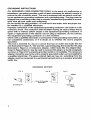
1
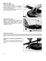
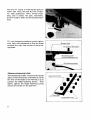
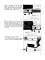
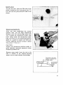
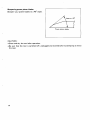
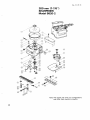
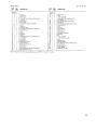
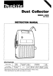
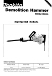
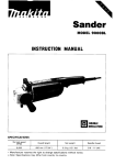
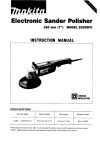
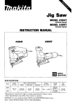
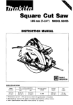
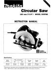
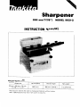
Sharpener
200 mm (7-718")
MODEL 9820-2
INSTRUCTION MANUAL
SPECIFICATIONS
Wheel size
200 mm x 25 mm x 75 mm
(7-7/8" x 1" x 3")
No load speed
560 R/min.
Overall length
390 mm ( 1 5-3/8")
Net weight
1 1 kg (24.3 Ibs)
BEFORE CONNECTING YOUR TOOL
TO A POWER SOURCE
Be sure you have read all
GENERAL POWER TOOL SAFETY RULES
GENERAL SAFETY PRECAUTIONS
(For All Tools)
1. KNOW YOUR POWER TOOL. Read the owner's manual carefully. Learn the
.
tools applications and limitations, as well as the specific potential hazards
peculiar t o it.
2. KEEP GUARDS IN PLACE and in working order.
3. REMOVE ADJUSTING KEYS AND WRENCHES. Form habit of checking t o
see that keys and adjusting wrenches are removed from tool before turning
it on.
4. KEEP WORK AREA CLEAN. Cluttered areas and benches invit? accidents.
5. DON'T USE IN DANGEROUS ENVIRONMENT. Don't use power tools in damp
or wet locations, or expose them t o rain. Keep work area well lighted.
6. KEEP CHILDREN AWAY. All visitors should be kept safe distance from work
area.
7. MAKE WORKSHOP KID PROOF with padlocks, master switches, or by
removing starter keys.
8. DON'T FORCE TOOL. It will do the job better and safer at the rate for which
it was designed.
9. USE RIGHT TOOL. Don't force tool or attachment t o do a job for which it
was not designed.
IO. WEAR PROPER APPAREL. Wear no loose clothing, gloves, neckties, rings.
bracelets, or other jewelry which may get caught in moving parts. Nonslip
footwear is recommended. Wear protective hair covering t o contain long hair.
1 1. ALWAYS USE SAFETY GLASSES. Also use face or dust mask if cutting operation is dusty. Everyday eyeglasses only have impact resistant lenses, they
are NOT safety glasses.
12. SECURE WORK. Use clamps or a vise t o hold work when practical. It's safer
than using your hand and it frees both hands t o operate tool.
13. DON'T OVERREACH. Keep proper footing and balance at all times.
14.MAINTAIN TOOLS WITH CARE. Keep tools sharp and clean for best and
safest performance. Follow instructions for lubricating and changing accessories.
15. DISCONNECT TOOLS before servicing; when changing accessories such as
blades, bits, cutters, and the like.
16. REDUCE THE RISK OF UNINTENTIONAL STARTING. Make sure switch is
in off position before plugging in.
L
17. USE RECOMMENDED ACCESSORIES. Consult the owner's manual for
recommended accessories. The use of improper accessories may cause risk
of injury t o persons.
18. NEVER STAND ON TOOL. Serious injury could occur if the tool is tipped or
if the cutting tool is accidentally contacted.
19. CHECK DAMAGED PARTS. Before further use of the tool, a guard or other
part that is damaged should be carefully checked t o determine that it will
operate properly and perform its intended function - check for alignment
of moving parts, binding of moving parts, breakage of parts, mounting, and
any other conditions that may affect its operation. A guard or other part that
is damaged should be properly repaired or replaced.
20. DIRECTION OF FEED. Feed work into a blade or cutter against the direction
of rotation of the blade or cutter only.
21. NEVER LEAVE TOOL RUNNING UNATTENDED. TURN POWER OFF. Don't
leave tool until it comes t o a complete stop.
22. PROPER GROUNDING. This tool should be grounded while in use t o protect
the operator from electric shock.
23. EXTENSION CORDS: Use only three-wire extension cords which have threeprong grounding-type plugs and three-pole receptacles which accept the
tool's plug. Replace or repair damaged or worn cord immediately.
VOLTAGE WARNING: Before connecting the tool t o a power source (receptacle,
outlet, etc.) be sure the voltage supplied is the same as that specified on the
nameplate of the tool. A power source with voltage greater than that specified
for the tool can result in SERIOUS INJURY t o the user - as well as damage t o
the tool. If in doubt, DO NOT PLUG IN THE TOOL. Using a power source with
voltage less than the nameplate rating is harmful t o the motor.
3
GROUNDING INSTRUCTIONS
.
.
ALL GROUNDED, CORD-CONNECTED TOOLS: In the event of a malfunction or
breakdown, grounding provides a path of least resistance for electric current t o
reduce the risk of electric shock. This tool is equipped with an electric cord having an equipment-grounding conductor and a grounding plug. The plug must be
plugged into a matching outlet that is properly installed and grounded in accordance with all local codes and ordinances.
Do not modify the plug provided - if it will not fit the outlet, have the proper outlet installed by a qualified electrician.
Improper connection of the equipment-grounding conductor can result in a risk
of electric shock. The conductor with insulation having an outer surface that is
green with or without yellow stripes is the equipment-grounding conductor. If
repair or replacement of the electric cord or plug is necessary, do not connect
the equipment-grounding conductor t o a live terminal.
Check with a qualified electrician or serviceman if the grounding instructions are
not completely understood, or if in doubt as t o whether the tool is properly
grounded.
This tool is intended for use on a circuit that has an outlet that looks like the
one illustrated in Figure A. The tool has a grounding plug that looks like the plug
illustrated in Figure A. A temporary adapter, which looks like the adapter illustrated in Figure B and C, may be used t o connect this plug t o a 2-pole receptacle
as shown in Figure B if a properly grounded outlet is not available. The temporary
adapter should be used only until a properly grounded outlet can be installed by
a qualified electrician. The green-colored rigid ear, lug, etc. extending from the
adapter must be connected t o a permanent ground such as a properly grounded
outlet box.
GROUNDING METHODS
FIG. A
FIG. B
FIG. C
Adapter
QI
Grounding Pin
4
-Cover of
Grounded
Outlet Box
Grounding
Means
ADDITIONAL SAFETY RULES
1. Use only wheels having a maximum operating speed at least as high as "No
Load RPM" marked on the tool's nameplate.
2. Check the wheel carefully for cracks or damage before operation. Replace
cracked or damaged wheel immediately.
3. Secure the wheel carefully.
4. Be careful not t o damage the spindle or the bolt, or the wheel itself might
break.
5. Keep a space of 5 m m (3/16") between the sharpening platform guide (rail)
and the grinding wheel.
6. Keep hands away from rotating parts.
7. Make sure the workpiece is not contacting the wheel before the switch is
turned on.
8. Before using the tool on an actual workpiece, let it run for several minutes.
Watch for flutter that might be caused by incorrect installation or a poorly
balanced wheel.
9. Use the upper surface of the wheel only. Don't use the side surface.
10. If the wheel stops during operation, makes an odd noise or begins t o vibrate,
switch off the tool immediately.
11. Always switch off and wait for the wheel t o come t o a complete stop before adjustment or inspection.
12. Do not touch the workpiece immediately after operation, it may be extremely
hot and could burn your skin.
13. Dry the wheel by idling the tool after operation t o prevent the wheel from
freezing in cold weather. Freezing can crack the wheel.
14. Store wheels in a dry location only.
SAVE THESE INSTRUCTIONS.
WARNING
For Your Own Safety Read Instruction
Manual Before Operating Grinder
1.
2.
3.
4.
5.
6.
Wear eye protection.
Use grinding wheel suitable for speed of grinder.
Replace cracked wheel immediately.
Always use guards and eye shields.
Do not overtighten wheel nut.
Use only flanges furnished with the grinder.
5
HOW TO USE
Replacing grinding wheel
Use the wrench provided to release the
grinding wheel by turning the installation
screw counterclockwise.
To install the grinding wheel, follow the
removal procedure in reverse.
Adjusting wheel guard
The top of the wheel guard should be 1 mm
(approx. 1/3") below the surface of the
grinding wheel. Adjust height by turning
the guard clockwise to lower it, or counterclockwise to raise it.
Wiping off the antirust
Wipe off the antirust on the sharpening platform guide (rail) and the sharpening holder.
Coat the sharpening platform guide and the sharpening holder with machine oil or spindle
oil.
Removing or installing sharpening platform
guide
To remove the sharpening platform guide,
loosen the screw and slip the set plate
aside.
6
Loosen the pole fastening screws and lift
off the sharpening platform guide.
To install the sharpening platform guide,
follow the removal procedure in reverse.
Adjusting sharpening platform guide
In using the sharpening platform guide to
sharpen blade/knife, adjust the angle adjustment screw to the desired blade/knife
sharpening angle. The bevel becomes acute
as the angle adjustment screw is turned
clockwise.
The platform poles are fixed in place by
tightening the pole fastening screws on
either side.
Sharpening platform
guide (Rail)
Pole
7
The nut for raising or lowering the pole on
either side raises the pole 0.5 mm (1/32")
for each graduation, when turned clockwise, and it lowers the pole, conversely,
0.5 mm (1/32") when turned counterclockwise.
Tilt the sharpening platform guide slightly
with right side downward so that the blade
contacts the right side surface of the grinding wheel.
Adjusting sharpening holder
I
The sharpening holder horizontal (forward)
adjust screws should be unscrewed to allow
the heel of the blade to be inserted so as to
contact the blade fastening screws. Then
lightly tighten the blade fastening screws
and set the holder on the platform.
Blade
-
I
I
8
Forward adiurt screw
\
\
I
I
Screw in clockwise the forward adjust
screw on the right until the right upper
edge of the blade comes into contact with
the grinding wheel. Then fully tighten the
fastening screw on the far right.
Slide the holder to the right across the
sharpening platform guide. Screw in the
left-hand forward adjust screw until the
left upper edge of the blade contacts the
grinding wheel. Now use all four fastening screws to secure the blade on the
horizontal.
Installing coolant reservoir (Tank)
Insert the reservoir legs into the grooves
provided for them on the sharpener frame.
9
Adjusting coolant flow
Put water in the coolant reservoir.
Turn the knob so that the marking i s positioned vertically to make the coolant flow.
Turn the marking to the horizontal position to stop the coolant flow.
NOTE :
Adjust the coolant flow adequately. If the
debris from the grinding wheel and the
blade is washed away by the coolant, the
coolant flow is excessive.
Draining used coolant
The used coolant drains out through the
drain hose (vinyl tube) provided. Have a
pan or drain system ready to catch it.
10
r
Switch action
To start the tool, press the ON side of the
switch located on the front of the tool. To
turn the tool off, press the OFF side of the
switch.
Sharpening blade/knife
1
1
After you have established the correct
coolant flow, you can begin sharpening.
Sharpen with the cutting edge away from
you, holding the sharpening holder with
both hands. Slide the sharpening holder
back and forth on the sharpening platform
guide a t a speed of about ten times per
minute, applying uniform pressure (about
5 kg; about 11 Ibs) on it.
CAUTION :
Always use sharpening platform guide or
guide assembly (optional accessory) when
sharpening bladdknife.
Remove some stock from the tip to the
heel in relation to the original grinding
angle so as to create a better cutting edge.
Take down this area
slightly in relation t o
A o r i g i l a l angle
Original (proper)
grinding angle
Tip (correct
sharpening
11
Sharpening power planer blades
Sharpen your planer blades to a 40" angle.
Power planer blade
CAUTION :
*Clean and dry the tool after operation.
0 Be sure that the tool is switched off, unplugged and drained before attempting to move
the tool.
12
MAINTENANCE
CAUTION :
Always be sure that the tool i s switched off and unplugged before attempting to perform
inspection and maintenance.
To maintain product SAFETY and RELIABILITY, repairs, any other maintenance and
adjustment should be performed by Makita Authorized or Factory Service Centers,
always using makita replacement parts.
ACCESSOR I ES
CAUTION :
These accessories or attachments are recommended for use with your Makita tool specified i n this
manual. The use of any other accessories or attachments might present a risk of injury to persons.
The accessories or attachments should be used only in the proper and intended manner.
0
Grinding wheels
Wrench
Part No. 341 391 - 3
Size (mm)
I
Grit
I
Part No.
Guide assembly
(Sharpening platform guide)
For sharpening scissors or knife.
Part No. 132386-5
200x25~75
(7-7/8" x 1 " x 3 " )
741074-9
13
Aug.-02-84
US
200 mm (7-7/8")
SHARPENER
Model 9820-2
Note: The switch and other part configurations
may differ from country to country.
14
MODEL
9820.2
Sep-19-'84
,":,
SDDESCRIPTION
6
7
8
9
10
11
12
13
14
15
16
17
18
19
20
22
23
24
25
26
27
28
29
1
1
1
2
2
2
1
2
1
1
1
2
1
1
1
1
1
1
1
1
1
1
1
1
1
1
4
1
-
DESCRIPTION
MACHINE
MACHINE
1
2
3
4
5
US
Knob 6 5
Vinyl Tube
Wheel Cover
Pan Head Screw M5x20 (With Washer)
set Plate
Screw M6x31
Name Plate
Countersunk Head Screw M3x6
Switch
capacotor
Capacttor Clamp
Pan Head Screw M5x20 IWith WasHerl
Thumb Pipe 20
Tank
Spindle
0 Ring 40
Frame
Pan Head Screw M4x12 IWith Washell
Strain Relief
Cord Guard
Rubber Pin 4
Ball Bearlng 6202LLB
Helical Gear 38
Ball Bearing 6201LLB
Rubber Pin 4
Gear Cover
Pan Head Screw M5x28 IWilh Washer)
Retaining Ring S - 1 2
30
31
32
1
1
1
33
34
35
2
2
1
3
1
1
1
1
1
1
1
1
1
1
1
1
36
37
38
39
40
41
42
43
44
45
46
47
48
49
50
51
100
101
102
103
-
1
1
2
5
1
4
1
neilcaiG~~~ 12
MOW,
CORD ASSEMBLY
IASSembled Cord Plug & Item 20)
Flat Washer 10
HEX Boll M10x30 lW8th Washer)
Under Cover
Pan Head Screw M4x6 IWlth Washer)
Wing Nut M 1 6
Pin 6
Sub Pole
Screw M6x41
Wmg Nut M 1 6
Flat Washer 6
Compression Spring 7
Main Pole
Rail
Torsion Spring 8
+ Pan Head Screw M 6
Band
Flat Washer 6
IhSUl.lfOn Paper
Pan Head Screw M4x8 IWith Washerl
Screw M6x71
Blade Holder 400
Screw M6x18
Blade Set Plate 400
-
Note The Switch and Other pari speclflcatlons may dlffer from country to country.
15
MAKITA LIMITED ONE YEAR WARRANTY
Warranty Policy
Every Makita tool is thoroughly inspected and tested before leaving the factory. It is warranted to
be free of defects from workmanship and materials for the period of ONE YEAR from the date of
original purchase. Should any trouble develop during this one-year period, retum the COMPLETE
tool, freight prepaid, to one of Makita’s Factory or Authorized Service Centers. If inspection shows
the trouble is caused by defective workmanship or material, Makita will repair (or at our option,
replace) without charge.
This Warranty does not apply where:
repairs have been made or attempted by others:
repairs are required because of normal wear and tear:
0 The tool has been abused, misused or improperly maintained;
alterations have been made to the tool.
IN NO EVENT SHALL MAKITA BE LIABLE FOR ANY INDIRECT, INCIDENTAL OR CONSEQUENTIAL DAMAGES FROM THE SALE OR USE OF THE PRODUCT. THIS DISCLAIMER
APPLIES BOTH DURING AND AFTER THE TERM OF THIS WARRANTY.
MAKITA DISCLAIMS LIABILITY FOR ANY IMPLIED WARRANTIES, INCLUDING IMPLIED
WARRANTIES OF “MERCHANTABILITY” AND “FITNESS FOR A SPECIFIC PURPOSE,”
AFTER THE ONE-YEAR TERM OF THIS WARRANTY.
This Warranty gives you specific legal rights, and you may also have other rights which vary from
state to state. Some states do not allow the exclusion or Limitation of incidental or consequential
damages, so the above limitation or exclusion may not apply to you. Some states do not allow
limitation on how long an implied warranty lasts, so the above limitation may not apply to you.
Makita Corporation
3-11-8, Sumiyoshi-cho,
Anjo, Aichi 446 Japan
003277 - 062 C
PRINTED IN JAPAN
1991 - 8 - N