1
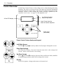
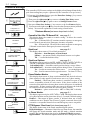
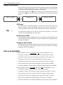
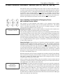
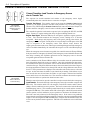
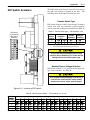
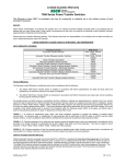
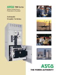
User’s Guide cut–out opening in enclosure door Group 5 Controller for 4000 & 7000 Series Automatic Transfer Switch Products 4–line LCD display Enter/Save Settings key Refer to the Operator’s Manual for the ASCO 4000 or 7000 Series ATS product for installation, functional testing, sequence of operation,and troubleshooting. Description ASCO 4000 & 7000 Series Automatic Transfer Switch products utilize the Group 5 Controller for sensing, timing, and control functions. This state–of–the art microprocessor–based controller includes a built–in keypad and a four–line LCD display. All monitoring and control functions can be done with the enclosure door closed for greater convenience. In addition, all changes in voltage settings (except for nominal voltage) and time delays can be made through a system of menus. TABLE OF CONTENTS section-page OVERVIEW Controls . . . . . . . . . . . . . . . . . . . . . . . . . . . . . . 1-1 Settings . . . . . . . . . . . . . . . . . . . . . . . . . . . . . . 1-2 Esc key Increase (up)/ Menu Scroll Decrease (down) Value keys (left/right) keys Power Control Center keypad and display DANGER is used in this manual to warn of high voltages capable of causing shock, burns, or death. WARNING is used in this manual to warn of possible personal injury. CAUTION is used in this manual to warn of possible equipment damage. Refer to the outline and wiring drawings provided with the 4000 or 7000 Series ATS product for all installation and connection details and accessories. SETTINGS How to Change a Setting . . . . . . . . . . . . . . . 2-1 Voltage & Frequency . . . . . . . . . . . . . . . . . . . 2-2 Time Delays . . . . . . . . . . . . . . . . . . . . . . . . . . 2-4 Features . . . . . . . . . . . . . . . . . . . . . . . . . . . . . . 2-6 General . . . . . . . . . . . . . . . . . . . . . . . . . . . . . . 2-8 Engine Exerciser . . . . . . . . . . . . . . . . . . . . . 2-10 View Event Log . . . . . . . . . . . . . . . . . . . . . . . 2-12 Service — Statistics / Diagnostics . . . . . . 2-13 OPERATING the CONTROLS Status of ATS and Sources . . . . . . . . . . . . . 3-1 Display Messages and Their Meanings . . . 3-2 DESCRIPTION of OPERATION Open–Transition . . . . . . . . . . . . . . . . . . . . . . . 4-1 Closed–Transition . . . . . . . . . . . . . . . . . . . . . . 4-3 Delayed–Transition . . . . . . . . . . . . . . . . . . . . 4-6 APPENDIX DIP switch actuators . . . . . . . . . . . . . . . . . . . A-2 Voltage jumper blocks . . . . . . . . . . . . . . . . . A-4 INDEX . . . . . . . . . . . . . . . . . . . . . . . . . . back page 50 Hanover Road, Florham Park, New Jersey 07932–1591 USA For sales or service call 1 800 800–2726 (ASCO) www.ascopower.com ASCO POWER TECHNOLOGIES CANADA PO Box 1238, 17 Airport Road, Brantford, Ontario, Canada N3T 5T3 telephone 519 758–8450, fax 519 758–0876, for service call 1 888 234–2726 (ASCO) www.asco.ca 381333–126 K 1--1 Overview Control Overview On the Power Control Center, six keys allow access to all monitoring and setting functions. Two levels of screens are used. The status level provides information about the automatic transfer switch. The settings level allows configuration of the controller. Access to some settings may require entering a password (if the controller is set for one – see page 2–1 and Appendix A–3). top 2 lines show the cause of any action 4–line LCD display lower 2 lines show the status of transfer sequence tactile keys (see below) Power Control Center display and keypad. Left–Right Arrows The left A and right " arrow keys (Menu Scroll) navigate through the screens. Enter/Save Settings The Enter/Save Settings ¿ key move from the status level to the settings level screens. It also is used to enter a new setting. Up–Down Arrows The up Y and down B arrow keys (Increase Value and Decrease Value) modifies a setting (setup parameter) while in the settings level screens. Esc key The Esc key ignores a change and returns to the status level. Overview Settings Overview 1--2 The controller settings can be displayed and changed from the keypad. Some settings may require a password (if the controller is set up for one). From the ATS Status display, press Enter/Save Settings ¿ key to move to the Settings level of menus. SETTINGS Press the right arrow key " to see the eight parameter information headings (as shown below). An overview of each setting is listed below. The detailed menus for each setting are on the following pages. 8 Parameter Menus (loop back to beginning) SETTINGS Voltage DO PU Frequency DO PU SETTINGS SETTINGS Time Delays Features SETTINGS SETTINGS General Engine Exerciser VIEW SERVICE SERVICE Event Log Statistics Diagnostics Factory Selectable Features Voltage and Frequency Settings see page 2–2 Time Delay Settings see page 2–4 Features Settings see page 2–6 General Settings see page 2–8 Engine Exerciser Settings see page 2–10 View Event Log see page 2–12 CP settings and Normal & Emergency voltage and frequency pickup & dropout. Bypass running time delay, and settings for all standard time delays. Commit on transfer, shed load, phase rotation, and inphase monitor settings. Reset settings, language, communication, logging, and password. Present date and time, seven exercise programs each with six parameters. Last 99 events in date and time order; six types and seven reasons are logged. Service Statistics/Diagnostics, Factory Selectable Features For factory service use only. see pages 2–13 2--1 Settings How to Change a Setting To change a setting in the controller (CP): ¡ ¡ Navigate to the settings screen that you want to change (see page 1–2). © © Press Enter/Save Settings ¿ key to start the first field blinking. If the controller requires a password, see below. ¢ ¢ Press up Y and down B arrow keys to change flashing digit(s) or word and press Enter/Save Settings ¿ key to move to next field. £ £ Repeat step ¢ Tips ☞ until all the fields have been entered. If a field is blinking, the CP is waiting for information to be entered. The Esc key will end the editing session. Password Tip ☞ Default password is 1111 (see page 2–8) If Enter Password displays, you must enter the correct password first. Enter Password 0000 Use the up Y and down B arrow keys to change the flashing digit of the password. Press the Enter/Save Settings ¿ key to move to next next digit (left to right). When the correct password is displayed, press the Enter/ Save Settings ¿ key. If WRONG PASSWORD !!! displays, you are returned to the first flashing digit. When the correct password is displayed, press the Enter/Save Settings ¿ key. You can now change the settings on the selected screen. Tip ☞ Once the password is entered it will stay unlocked for 5 minutes after last key is pushed so that you do not have to keep entering it. So, to save time, plan to make all your settings at one time. Settings 2---2 Voltage & Frequency Settings Unless otherwise specified on the order, the controller voltage and frequency settings are set at the factory to the default values. If a setting must be changed, carefully follow the procedure on the next page. Some settings may require a password (if the controller is set up for one). Any indiscriminate change in these settings may affect the normal operation of the Automatic Transfer Switch. This change could allow the load circuits to remain connected to an inadequate source. Description Normal Source Voltage Emergency Source Voltage Normall N Source Frequency Emergency E Source Frequency Settings Default Setting % of nominal Adjustment Range increments of 1% Display Screen (see next page) Dropout 85 % 70 to 98 % NORMAL VOLTAGE Dropout Pickup 90 % 85 to 100 % NORMAL VOLTAGE Pickup Over Voltage Trip * off 102 to 115 % NORMAL VOLTAGE OV Trip Unbalance Enable no yes or no NORMALVOLTAGEUNBAL Enable Unbalance Dropout 20 % 5 to 20 % NORMALVOLTAGEUNBAL Dropout Unbalance Pickup 10 % 3 to 18 % NORMALVOLTAGEUNBAL Pickup Dropout 75 % 70 to 98 % EMERG VOLTAGE Dropout Pickup 90 % 85 to 100 % EMERG VOLTAGE Pickup Over Voltage Trip * off 102 to 115 % EMERG VOLTAGE OV Trip Unbalance Enable no yes or no EMERG VOLTAGE UNBAL Enable Unbalance Dropout 20 % 5 to 20 % EMERG VOLTAGE UNBAL Dropout Unbalance Pickup 10 % 3 to 18 % EMERG VOLTAGE UNBAL Pickup Dropout 90 % 85 to 98 % NORMAL FREQUENCY Dropout Pickup 95 % 90 to 100 % NORMAL FREQUENCY Pickup Over Frequency Trip * off 102 to 110 % NORMAL FREQUENCY OF Trip Dropout 90 % 85 to 98 % EMERG FREQUENCY Dropout Pickup 95 % 90 to 100 % EMERG FREQUENCY Pickup Over Frequency Trip * off 102 to 110 % EMERG FREQUENCY OF Trip * The Over Voltage and Over Frequency reset is fixed at 2% below the trip setting. 2--3 Settings Voltage & Frequency Settings The controller (CP) voltage and frequency setting can be displayed and changed from the keypad. See the table on the previous page. Some settings may require a password (if the controller is set up for one). ¡ From any of the Status displays, press the Enter/Save Settings ¿ key to move to the Settings level of menus. ¡ © Press the Enter/Save Settings ¿ key to move to the CP Settings display. SETTINGS Voltage DO PU Frequency DO PU © ¢ Then you can press the right arrow " key to see the other voltage and frequency displays (as shown below). An overview explanation of each setting is listed below. 5 Voltage & Frequency Menus (last menu loops back to first) CP SETTINGS Volt= V Freq= Hz Phase= N: Ph E: Ph ATS Type= TS ¢ NORMAL VOLTAGE Dropout: % V Pickup: % V OV Trip: _ NORMAL FREQUENCYDropout: % Hz Pickup: % Hz OF Trip: _ NORMAL VOLTAGE UNBAL Enable: NO Dropout: 20% Pickup: 10% _ EMERG VOLTAGE Dropout: % V Pickup: % V OV Trip: _ CP Settings see page 2–1 Normal Voltage see page 2–1 Normal Frequency see page 2–1 Normal Voltage Unbalance see page 2–1 Emerg Voltage see page 2–1 Emerg Frequency see page 2–1 This display shows the base configuration of the controller. These settings are hardware activated and cannot be changed from the keypad: Nominal source voltage — Normal and Emergency sources Nominal source frequency — 50 or 60 Hz Normal & Emergency source sensing — single or 3 phase Switch type — open, closed, or delayed transition This display shows pickup, dropout, and over–voltage trip settings for the Normal source. They are in percentage of nominal voltage and volts rms. This display shows pickup, dropout, and over–frequency trip settings for the Normal source. They are in percentage of nominal frequency and Hz. This display appears only if the CP is set for 3 phase sensing on Normal. When enabled, the CP considers the Normal source unacceptable if the calculated voltage unbalance is greater than the specified dropout. This display shows pickup, dropout, and over–voltage trip settings for the Emergency source. They are in percent of nominal voltage and volts rms. This display shows pickup, dropout, and over–frequency trip settings for Emergency source. They are in percentage of nominal frequency and Hz. EMERG FREQUENCYDropout: % Hz Pickup: % Hz OF Trip: _ Emerg Voltage Unbalance (not shown) see page 2–1 This display appears only if the CP is set for 3 phase sensing on Emergency. When enabled, the CP considers the Emergency source unacceptable if the calculated voltage unbalance is greater than the specified dropout. Settings 2---4 Time Delay Settings Unless otherwise specified on the order, the Controller time delay settings are set at the factory to the default values. If a setting must be changed, follow the procedure on the next page. Some settings may require a password (if controller is set up for one). Any indiscriminate change in these settings may affect the normal operation of the Automatic Transfer Switch. This change could allow the load circuits to remain connected to an inadequate source. Feature Time Delay Default Setting Adjustment Range 1 sec. increments Display Screen (see next page) 1C ③ override momentary Normal source outages 1 second 0 to 6 sec see CAUTION below TD NormFail 1F override momentary Emergency source outages 0 0 to 60 min 59 sec TD EmrgFail 2B transfer to Emergency 0 0 to 60 min 59 sec TD N>E 2E unloaded running (engine cooldown) 5 minutes 0 to 60 min 59 sec TD EngCool retransfer to Normal (if Normal fails) 30 minutes 0 to 60 min 59 sec TD E>N if Normal Fail retransfer to Normal (if just a test) 30 seconds 0 to 9 hours 59 min 59 sec TD E>N if Test Mode 31F ④ Normal to Emergency pre–transfer signal 0 0 to 5 min 59 sec TD N>E Xfer Signal PreXfer 31M ④ Normal to Emergency post–transfer signal 0 0 to 5 min 59 sec TD N>E Xfer Signal PostXfer 31F, 31M bypass 31F & 31M if Normal fails no yes or no TD N>E Xfer Signal BypassIfNFail 31G ④ Emergency to Normal pre–transfer signal 0 0 to 5 min 59 sec TD E>N Xfer Signal PreXfer 31N ④ Emergency to Normal post–transfer signal 0 0 to 5 min 59 sec TD E>N Xfer Signal PostXfer 31G, 31N bypass 31G & 31N if Emergency fails no yes or no TD E>N Xfer Signal BypassIfEFail in sync 1.5 second 0 to 3.0 seconds 0.1 sec increments CTTS TD SyncMonitorTD failure to synchronize 5 minutes 0 to 5 min 59 sec CTTS TD FailToSyncTD extended parallel time 0.5 second 0.100 to 1.000 sec 0.01 sec increments CTTS TD XtdParallelTD delay transition time 0 0 to 5 min 59 sec DTTS TD LoadDisconnDelay 3A 4ACTS, 7ACTS, 7ACTB only l ① 4ADTS, 7ADTS/B only② ① These time delays appear only on the display for a 4ACTS, 7ACTS, or 7ACTB closed–transition transfer switch. ② This time delay appears only on the display for a 4ADTS, 7ADTS, or 7ADTB delayed–transition transfer switch ③ Standard adjustment up to 6 seconds (total power outage). For additional time delay contact ASI. See CAUTION. ④ If output contacts required, contact ASI at 1–800–800–2726. Do not set Feature 1C TD longer than 6 sec. unless an external 24 V dc power supply is included. Contact ASI if longer than 6 sec. is required. 2---5 Settings Time Delay Settings The controller time delay (TD) settings can be displayed and changed from the keypad. Some settings may require a password (if the control panel is set up for one). ① From any of the Status displays, press the Enter/Save Settings key to move to ① the Settings level of menus. SETTINGS ② Press the right arrow key to move to the Setting Time Delays display. Voltage DO PU Frequency DO PU ③ Now press Enter/Save Settings key to move to the first Time Delay menu. ② ④ You can press the right arrow key to see the other time delay menus (as shown below). An overview explanation of each setting is listed below. SETTINGS 5 Time Delay Menus (last menu loops back to first) Bypass Currently Running TD see page 2–1 Time Delays This display allows you to bypass some time delays. When the display is set to Yes the controller will bypass any of these time delays Feature 1C — Momentary Normal failure time delay Feature 2B — Normal to Emergency transfer time delay Feature 3A — Emergency to Normal transfer time delay External Battery: see CAUTION on bottom of page 2–4 Yes means external battery connected, Feature 1C can be set longer than 6 sec. No mean there is no external battery, Feature 1C can be set for 0–6 sec. only ③ Bypass Currently Running TD: _ External Battery: No ④ TD NormFail: TD N>E: TD EmrgFail: TD EngCool: min min min min s s s s TD E>N if Normal Fail: Test Mode: h min min s s TD N>E Xfer Signal BypassIfNFail: PreXfer: min s PostXfer: min s TD E>N Xfer Signal BypassIfEFail: PreXfer: min s PostXfer: min s Standard Time Delays see page 2–1 TD E>N if see page 2–1 TD N>E Xfer Signal see page 2–1 TD E>N Xfer Signal see page 2–1 CTTS TDs (not shown) see page 2–1 DTTS TD (not shown) see page 2–1 This display shows the settings for the following standard time delays: Feature 1C — Momentary Normal source failure time delay Feature 2B — Normal to Emergency transfer time delay Feature 1F — Momentary Emergency source failure time delay Feature 2E — Engine cooldown time delay This display shows the settings for Feature 3A retransfer to Normal time delay. There are two modes: Normal source outage — retransfer TD if Normal fails Transfer Test — retransfer TD if just a test This display shows the settings for the time delays used to signal external equipment before and after transfer from Normal to Emergency: Feature 31F — Pre–transfer time delay signal Feature 31M — Post–transfer time delay signal This display shows the settings for the time delays used to signal external equipment before and after retransfer from Emergency to Normal: Feature 31G — Pre–transfer time delay signal Feature 31N — Post–transfer time delay signal Settings 2---6 Features Settings Unless otherwise specified on the order, the controller features settings are set at the factory to the default values. If a setting must be changed, follow the procedure on the next page. Some settings may require a password (if the controller is set up for one). Any indiscriminate change in these settings may affect the normal operation of the Automatic Transfer Switch. This change could allow the load circuits to remain connected to an inadequate source. Feature Default Setting Adjustment Range Display Screen (see next page) commit to transfer no yes or no Commit to Xfer After TD Norm Fail shed load direction from E from N or from E SHED LOAD Direction shed load in phase no yes or no SHED LOAD InPhase shed load in phase time delay 1.5 second 0 to 3.0 seconds 0.1 sec increments SHED LOAD TD shed load isolate load on source failure ② yes yes or no SHED LOAD IsoLoadOnSrcFail no yes or no SHED LOAD IsoLoadOnTest17 phase rotation monitor enable ③ no yes or no PHASE ROTATION MONITOR Enable phase rotation monitor reference ③ ABC ABC or CBA PHASE ROTATION MONITOR Reference inphase monitor enable ④ no yes or no IN–PHASE MONITOR Enable inphase monitor time delay ④ 1.5 second 0 to 3.0 seconds 0.1 sec increments IN–PHASE MONITOR Time Delay failure to sync auto bypass ① no yes or no CTTS BYPASS/SHED LD FailSyncAutoByps bypass time delay ① 0 second 0 to 59 seconds 1 sec increments CTTS BYPASS/SHED LD Bypass DT Delay bypass in phase ① no yes or no CTTS BYPASS/SHED LD Bypass InPhase Y–Y primary failure detection enable no yes or no Y–Y PRI FAIL DETECT Enable Y–Y primary failure sensing time delay 1.0 second 0 to 9.9 seconds 0.1 sec increments Y–Y PRI FAIL DETECT Sense Delay Y–Y primary failure retransfer time delay 1.0 hour 0 to 23 hrs 59 min. 1 min. increments Y–Y PRI FAIL DETECT TD E>N Y–Y shed load isolate load on test 17 ② ① These features appear only on the display for a 4ACTS, 7ACTS, or 7ACTB closed–transition transfer switch. ② These features appear only on the display for a 4ACTS, 7ACTS or 7ACTB closed–transition transfer switch or a 4ADTS, 7ADTS, or 7ADTB delayed–transition transfer switch. ③ These features do not appear on the display unless both sources have 3 phase sensing enabled. ④ These features appear only on a 4ATS, 7ATS, or 7ATB (open–transition automatic transfer switch). 2--7 Settings Features Settings ¡ From any of the Status displays, press the Enter/Save Settings ¿ key to move to the Settings level of menus. © Then press the right arrow " key to move to Setting Time Delays menu. ¢ Press the right arrow " key again to move to Settings Features menu. £ Now press Enter/Save Settings ¿ key to move to the first Features display ¤ You can press the right arrow " key to see the other Features menus (as shown below). An overview explanation of each setting is listed below. ¡ SETTINGS Voltage DO PU Frequency DO PU 7 Features Menus (last menu loops back to first) ©¢ Features £ ¤ SHED LOAD s SHED LOAD IsoLoadOnSrcFail IsoLoadOnTest17 yes no PHASE ROTATION MONITOR Enable: Reference: IN--PHASE MONITOR Enable: Time Delay: see page 2–1 Shed Load see page 2–1 Shed Load Options see page 2–1 Phase Rotation Monitor see page 2–1 In–Phase Monitor see page 2–1 This display shows status of 3 load shed parameters: Direction — from Emergency or from Normal InPhase — yes means transfer delayed until sources are in phase TD — 3 second default time delay Commit to Xfer After TD Normal Fail: _ TD: Commit to Xfer After TD Normal Fail This display shows the commit to transfer setting. It affects the transfer sequence as follows: Yes — If Normal fails, CP continues transfer sequence to emergency even if Normal returns before Emergency becomes acceptable. No — If Normal fails, CP cancels the transfer sequence to emergency if Normal returns before Emergency becomes acceptable. SETTINGS Direction: InPhase: The controller (CP) Features settings can be displayed and changed from the keypad. Some settings may require a password (if the controller is set up for one). This display appears only for 4ACTS, 4ADTS, 7ACTS, 7ACTB, 7ADTS, or 7ADTB. It determines switch position after the shed load transfer. IsoLoadOnSrcFail — determines switch position during a source failure. IsoLoadOnTest17 — deterines switch position during feature 17 activation. Yes — Load is not connected to either source. (see wiring diagram No — Load is connected to the opposite source. for feature 17 desc.) This display shows status of phase rotation monitor and desired reference phase rotation. It only appears if both sources are set to 3–phase sensing. Enabled — Yes means phase rotation is considered as part of the source acceptability criteria for each source. If the phase rotation of the source does not match the reference phase rotation, that source is considered unacceptable. If phase rotation of the two sources is different, the load will be transferred to the source with the reference phase rotation. Reference — phase rotation order: ABC or CBA (ABC is default) This display appears only for 4ATS, 7ATS or 7ATB. This display shows status of in–phase monitor and in–phase time delay (1.5 seconds is default setting). Enabled — Yes means in–phase transfer is initiated when any of these conditions are met: Transfer Test (Feature 5) signal, connected source fails, retransfer to acceptable Normal occurs and Emergency source acceptable. CTTS Bypass / Shed Load (not shown)see page 2–1 s This display shows status of the closed–transition bypass options. FailSyncAutoBypass — Yes means if the fail to sync alarm occurs, the controller will bypass the closed–transition mode and will make a delayed–transiton transfer. The load disconnect time is set by the Bypass DT Delay parameter. Bypass InPhase — Yes means the inphase monitor is active during load transfer. Settings 2---8 Y – Y Primary Failure Detection (not shown) see page 2–1 This display shows status of a special control algorithm which is described in Application Note 381339–276. Enable – Yes means the algorithm is activated to detect Normal primary single phase failure in Y–Y systems. Sense Delay — 1 second default time delay. TD E>N Y–Y — 1 hour default time delay. Note: This function should only be considered for use where the Normal source is provided through a Y–Y transformer. This function requires the Normal source voltage unbalance monitoring to be enabled. General Settings Unless otherwise specified on the order, the controller general settings are set at the factory to the default values. If a setting must be changed, follow the procedure on the next page. Some settings may require a password (if the controller is set up for one). Any indiscriminate change in these settings may affect the normal operation of the Automatic Transfer Switch. This change could allow the load circuits to remain connected to an inadequate source Default Setting Adjustment Range Display Screen (see next page) language ENGLISH* ENGLISH FRENCH CDN ENGLISH EU ENGLISH EU S1–S2 ENGLISH S1–S2* SPANISH GERMAN PORTUGUESE Menu Language ENGLISH serial communications baud rate 19.2k off, x9600, 9600, 19.2k, Mbus9600, Mbus19.2k SERIAL COMMUNICATION Baud Rate serial communications address 1 0 to 63 SERIAL COMMUNICATION Address event log enable no yes or no EVENT LOGGING Enable print enable no yes or no EVENT LOGGING Print Enable clear log no yes or no EVENT LOGGING Clear Log door–mounted user controls locked but not the Power Control Center (this setting on 4000 Series only) no yes or no Keypad Locked password 1111 4 characters letters or numbers Change Password Parameter * Note: If the language setting ENGLISH S1–S2 is selected the usual display words Normal (N) and Emergency (E) are changed to Source 1 (S1) and Source 2 (S2). 2--9 Settings General Settings The controller (CP) general setting can be displayed and changed from the keypad. Some settings may require a password (if the controller is set up for one). ¡ From any of the Status displays, press Enter/Save Settings ¿ key to move to the Settings level of menus. ¡ © Press the right arrow " key to move to Setting Time Delays menu. SETTINGS Voltage DO PU Frequency DO PU ¢ Press the right arrow " key again to move to Settings Features menu. £ Press the right arrow " key again to move to Settings General menu. © ¢£ ¤ Now press Enter/Save Settings ¿ key to move to the first General display SETTINGS General ¥ You can press the right arrow " key to see the other General menus (as shown below). An overview explanation of each setting is listed below. 6 General Settings Menus (last menu loops back to first) ¤ Default to Factory Settings: Reset Engine Exerc Programs: Default to Factory Settings see page 2–1 Reset Engine Exerc Programs see page 2–1 Menu Language (not shown) see page 2–1 Serial Communication see page 2–1 Event Logging see page 2–1 Print Event Log (not shown) see page 2–1 This display (upper half) allows the user to reset the majority of controller settings to their factory default values. This display (lower half) also allows the user to reset the engine exerciser routines. YES means reset. NO means do not reset. ¥ SERIAL COMMUNICATION Baud Rate: Address: EVENT LOGGING Enable: Print Enable: Clear Log: User Ctrls Lckd: Change Password: 0001 This display shows the language in which the messages will be shown. English is the default language. This display allows the user to configure the serial communications port of the controller. Baud Rate — off, 9600, x9600. 19.2 k, Mbus9600, Mbus19.2k x9600 selects 9600 and the Group 1/7 CP protocol Address — can be set from 0 to 63 This display allows the user to enable the event logging feature of the controller and to clear the event log. Enable — YES means to start event logging; NO means turn it off. Print Enable — YES means enables printer option; NO turns it off. Clear Log — YES means erase the event log; NO means keep it. This display shows the status of the optional printer. Also see Printer Interface Module instructions 381339---218. User Controls Locked (on 4000 Series only) see page 2–1 This display allows the user to lock or unlock the door–mounted user controls. (not the Power Control Center). YES means locked. NO means unlocked. Change Password see page 2–1 This display allows the user to change the controller password. Settings 2---10 Engine Exerciser Settings Unless otherwise specified on the order, the controller engine exerciser settings are set at the factory to the default values. If a setting must be changed, follow the procedure on the next page. Some settings may require a password (if the controller is set up for one). Any indiscriminate change in these settings may affect the normal operation of the Automatic Transfer Switch. This change could allow the load circuits to remain connected to an inadequate source Default Setting Adjustment Range Display Screen (see next page) month JAN JAN, FEB, MAR, APR, MAY, JUN, JUL, AUG, SEP, OCT, NOV, DEC PRESENT DATE/TIME Date day 1 1 to 31 PRESENT DATE/TIME Date year * 1 00 to 99 PRESENT DATE/TIME Date hour 1 0 to 23 PRESENT DATE/TIME Time minute 1 0 to 59 PRESENT DATE/TIME Time engine exerciser enable (P1 to P7) no yes or no P1 ENGINE EXERCISER Enable engine exerciser transfer load (P1 to P7) no yes or no P1 ENGINE EXERCISER wLoad engine exerciser start hour (P1 to P7) 0 0 to 23 P1 ENGINE EXERCISER Start h engine exerciser start minute (P1 to P7) 0 0 to 59 P1 ENGINE EXERCISER Start min engine exerciser run week (P1 to P7) all all, alternate, first, second, third, fourth, or fifth engine exerciser run day (P1 to P7) SUN SUN, MON, TUE, WED, THU, FRI, SAT engine exerciser duration hours (P1 to P7) 0 0 to 23 P1 ENGINE EXERCISER Run TIme h engine exerciser duration minutes (P1 to P7) 0 0 to 59 P1 ENGINE EXERCISER Run TIme min Parameter * For the year 2000, enter 00. 2---11 Settings Engine Exerciser Settings The controller (CP) engine exerciser setting can be displayed and changed from the keypad. Some settings may require a password (if the controller is set up for one). ① From any of the Status displays, press Enter/Save Settings key to move to the Settings level of menus. ① SETTINGS Voltage DO PU Frequency DO PU ②③ ④⑤ ② Press the right arrow key to move to Setting Time Delays menu. ③ Press the right arrow key again to move to Settings Features menu. ④ Press the right arrow key again to move to Settings General menu. SETTINGS Engine Exerciser ➅ ⑤ Press the right arrow key again to move to Settings Engine Exerciser. ➅ Now press Enter/Save Settings key to move to the first Engine Exerciser menu. ➆ You can press the right arrow key to see the other Engine Exerciser menus (as shown below). An overview explanation of each setting is listed below. PRESENT DATE/TIME US DST: Date: Time: 8 Engine Exerciser Settings Menus (last menu loops back to first) Present Date/Time ➆ see page 2–1 This display allows the user to change the controller date and time. P1 ENGINE EXERCISER Enable: wLoad: Start: h Run Time: h min US DST — US Daylight Saving Time. APR – OCT, MAR – NOV, or OFF. MAR – NOV begins in 2007. P(1—7) Engine Exerciser(s) Set the seven independent engine exercise routines, if desired. see page 2–1 These displays (P1 through P7) allow the user to set the controller’s seven independent engine exerciser routines. Each routine functions in the same manner. Six parameters need to be configured for each routine (P1, P2, P3, P4, P5, P6, P7 — not all have to be used). Enable — YES enables the routine; NO turns it off. wLoad — YES transfers load to Emergency; NO = no transfer. Start — when the routine will start the generator – time (hour, minute) – week (all, alternate, 1st, 2nd, 3rd, 4th, or 5th week) – day of the week (mon, tue, wed, thu, fri, sat, sun) P7 ENGINE EXERCISER Enable: wLoad: Start: h Run Time: h min Run Time — duration (length of time) that the generator will run. Settings View Event Log 2--12 The controller event logging feature can be displayed from the keypad. Some settings may require a password (if the controller is set up for one). ¡ From any of the Status displays, press Enter/Save Settings key to move to the Settings level of menus. ¡ © Press the right arrow " key to move to Setting Time Delays menu. SETTINGS ¢ Press the right arrow " key again to move to Settings Features menu. Voltage DO PU Frequency DO PU £ Press the right arrow " key again to move to Settings General menu. © ¢ £ ¤ VIEW Event Log ¥ ¤ Press the right arrow " key again to move to Settings Engine Exerciser. ¥ Press the right arrow " key again to move to View Event Log. ¦ Now press Enter/Save Settings key to move to the events logged display. ¦ § 1 No Event Recorded 2 No Event Recorded § Scroll " to show the last 99 logged events. 98 No Event Recorded 99 No Event Recorded You can press the right arrow " key to see the other events logged. An overview explanation of each setting is listed below. Logged Events This display shows the last 99 logged events. Each event display shows the event number (1 is the most recent, 99 is the oldest), the time and date of the event, the event type, and the event reason (if applicable). Event Types Nine types of events are logged. They are (displayed event & meaning) : Eng Start The controller has signaled the engine to start Xfer N>E The controller has initiated transfer from normal to emergency Xfer E>N The controller has initiated transfer from emergency to normal Eng Stop The controller has signaled the engine to stop EmergAcc The emergency source has become acceptable EmergNAccThe emergency source has become not acceptable NormAcc The normal source has become acceptable NormNAcc The normal source has become not acceptable XfrAbort The transfer has been aborted Event Reasons Twenty–one reasons for events are logged. They are (displayed reason & meaning): LoadShed Load shed requested NormFail Normal source failure NormOF Normal source over frequency ManualXfr Manual transfer NormPHR Normal source phase rotation Test 5 Test requested (Feature 5) NormVUNB Normal source voltage unbalance Test 17 Test requested (Feature 17) EmergUV Emergency source under voltage Comm Serial communications EmergOV Emergency source over voltage EngExerc Engine Exerciser EmergUF Emergency source under frequency EmergFail Emerg source failure EmergOF Emergency source over frequency NormUV Normal source under voltage EmergPHR Emergency source phase rotation NormOV Normal source over voltage EmergVUNB Emergency source voltage unbalance NormUF Normal source under frequency Feature 6 Feature 6 activated 2--13 Settings Service — Statistics / Diagnostics The controller service statistics / diagnostics can be displayed from the keypad. Some settings may require a password (if the controller is set up for one). ¡ From any of the Status displays, press Enter/Save Settings key to move to the Settings level of menus. ¡ SETTINGS Voltage DO PU Frequency DO PU ©¢£ ¤¥¦ press 6 times ©¢£¤¥¦ Press right arrow " key six times to move to Service menu. § Now press Enter/Save Settings key to move to the first Service menu. ¨ You can press the right arrow " key to see the other Service menus (as shown below). An overview explanation of each setting is listed below. SERVICE Statistics Diagnostics 7 Service Menus (last menu loops back to first) ATS Statistics § ATS STATISTICS ATS Total Xfers: SrcFailTotXfers: Days Energized: ¨ SOURCE STATISTICS TimeNAvl: h min TimeEAvl: h min This display shows the total number of transfers, the total number of transfers due to source failures, and the total number of days that the ATS has been energized since the controller has been installed. These values cannot be reset. Source Statistics This display shows the total time that the normal and emergency sources have been acceptable since installation of the controller. These values cannot be reset. View Service Data This display is for service personnel only. Serial Communication VIEW SERVICE DATA Addr: Data: SERIAL COMMUNICATION Loop Test: This display allows the user to test the serial communications port of the controller. To perform the test, the transmit lines of the serial communications port are connected to the receive lines so that the signals sent by the controller are also received by the controller. The test is activated by pressing the Enter/Save Settings key while viewing this display. If the controller receives the same information that it sent, test is passed, otherwise it fails. I/O Status (not shown) These displays show the status of several of the controller’s input and output lines. CP SOFTWARE Version: Date: CP Software This display shows the version of the loaded software and the date of its release. Settings 2--14 Service — Factory Selectable Features The controller service factory selectable features can be displayed from the membrane controls. These factory settings should not be changed by the customer (they cannot be changed without entering the factory password). NORMAL OK ¡ From the ATS Status display (NORMAL OK), press Enter/Save Settings button to move down to the Settings level of menus. ¡ ©¢£¤¥¦§ Press right arrow " button 7 times to move to Service menu. SETTINGS ¨ Now press Enter/Save Settings button to move down to the first Service factory selectable feature. Voltage DO PU Frequency DO PU ©¢£ ¤¥¦§ press 7 times SERVICE You can press the right arrow " button to see the other Service menus (as shown below). An overview explanation of each setting is listed below. 8 Service Menus (last menu loops back to first) Factory Selectable Features ATS Information This display shows the transfer switch ampere size, whether the switch is a bypass switch or a non–bypass switch, and any name or description inform– ation that has been assigned to it through the serial communications port. ¨ ATS INFORMATION ATS: TEST OR MANUAL MODE INPUT Test Operation: Manual Operation: RETRANSFER MODE INPUT TD Bypass: Manual Re Xfer: Test or Manual Mode Input This display shows the setting of the Feature 5/6Z input. This input can be used for either Feature 5 or 6Z. Yes means active; no means not used. Test Operation — Feature 5 Manual Operation — Feature 6Z This Feature is not available for automatic operation. Retransfer Mode Input This display shows the settings for Features 6B/6C inputs. This input can be used for either Feature 6B or 6C. Yes means active; no means not used. TD Bypass — Feature 6B Manual Re Xfer — Feature 6C These Features are typically set to Yes with the inhibit Feature overridden with external factory wiring. These Features are not available for customer use. Xfer to Normal Inhibit and Emergency (not shown) XFER TO NORMAL INHIBIT Enable: This display shows whether the Feature 34A input is enabled (yes) or disabled (no). Likewise, the next display Xfer to Emerg shows whether the Feature 34B input is enabled (yes) or disabled (no). Factory Calibration (not shown) This display is for factory calibration only and should be used by factory personnel only. Temp Calibr: ATS Idle Time: CT Parallel TD: ms ms Other These displays show various parameters that should be accessed by factory personnel only. 3--1 Operating the Controls Status Information The controller (CP) provides the status of the automatic transfer switch (ATS) and of both the normal and emergency sources. This information is at the status level of all screens and no password is required to view them. You can press the right arrow " key to see the status of the Normal Source or press the left arrow A key to see the status of the Emergency source (the menus loop back). EMERG SOURCE NORMAL OK NORMAL SOURCE ATS Status The ATS Status is the primary display. It shows the present status of the ATS. Transfer sequence status and running time delays are shown. For inphase or closed–transition transfers, phase relation between the sources is also shown. Tip ☞ The ATS Status display can be directly reached from anywhere in the menu structure by pressing the Esc key three times. Normal Source Status The Normal Source Status display shows the rms voltage of each of the phases, the source frequency in Hz, and the phase rotation. If enabled, the voltage unbalance will also be displayed. Emergency Source Status The Emergency Source Status display shows the rms voltage of each of the phases, the source frequency in Hz, and the phase rotation. If enabled, the voltage unbalance will also be displayed. Source Acceptability The CP considers a source unacceptable if any of these conditions are true: S Any phase voltage of the source is less than the voltage dropout setting. S Any phase voltage is greater than voltage trip setting for more than 3 sec. S Frequency of the source is less than the frequency dropout setting. S Frequency is greater than frequency trip setting for more than 3 seconds. S Phase rotation does not match specified phase rotation (only if enabled). S The phase unbalance is greater than the unbalance dropout setting (only if enabled). The CP considers a source acceptable again when all these conditions are true: S Each phase voltage is greater than the voltage pickup setting. S Each phase voltage is less than trip voltage setting by more than 2% of nom S The frequency of the source is greater than the frequency pickup setting. S Frequency is less than the frequency trip setting by more than 2% of nom. S Phase rotation matches the specified phase rotation (only if enabled). S The phase unbalance is less than the unbalance pickup setting (only if enabled). Operating the Controls 3--2 Display Messages and their Meaning The following messages (in alphabetical order) can appear on the CP display: Display Message Meaning or Explanation Also Refer To ATS LOCKED OUT! An error condition has occurred and the controller has locked out all further attempts to transfer the load. Press the Alarm Reset pushbutton to clear this message. Transfer Switch Operator’s Manual EMERG SOURCE The emergency status display shows the emergency voltages, voltage unbalance (if enabled), and frequency. page 3–1 ENGINE EXERCISE WITH LOAD The engine exerciser is running the engine– generator set with load (the transfer switch transfers the load to the generator). pages 2–10, 2–11 ENGINE EXERCISE WITHOUT LOAD The engine exerciser is running the engine– generator set without load (the transfer switch does not transfer the load to the generator). pages 2–10, 2–11 Enter Password: A password is required to proceed further in the change process. Enter the correct password to continue or press the Esc key to clear this message. pages 2–1, 2–8 FAILURE TO SYNCHRONIZE ALARM The failure to synchronize time delay has expired. This alarm occurs when the sources fail to synchronize within the specified time. Press the Alarm Reset pushbutton to clear this message. (4ACTS, 7ACTS, 7ACTB) pages 4–4, 4–5 Load Disconnected The load is disconnected (4ADTS,7ADTS,7ADTB) pages 4–6, 4–7 Load on Emerg The load is connected to the emergency source. Load on Normal The load is connected to the normal source. LOAD SHED FROM EMERG The load shed signal is active and the load has been shed from the emergency source. page 2–6 LOAD SHED FROM NORMAL The load shed signal is active and the load has been shed from the normal source. page 2–6 NORMAL FAILED The normal source is not acceptable. page 3–1 NORMAL OK The normal source is accepted. page 3–1 NORMAL SOURCE The normal status display shows the normal source voltages, voltage unbalance (if enabled), and frequency. page 3–1 POWER–UP INHIBIT stays on The controller has powered up and has recognized an error condition. Contact ASI TD Emerg>Normal: The emergency to normal load transfer time delay (Feature 3A) is running. The amount of time remaining is shown. page 2–4 TD Engine Cooldown: The engine–generator set unloaded cooldown time delay (Feature 2E) is running. The amount of time remaining is shown. page 2–4 TD Load Disconnect: The load disconnect time delay is running. The amount of time remaining is shown. (4ADTS, 7ADTS, 7ADTB) pages 4–6, 4–7 continued on next page 3--3 Operating the Controls Display Messages and their Meaning (continued) The following messages (in alphabetical order) can appear on the CP display: Display Message Meaning or Explanation Also Refer To TD Normal Fail: The normal source failure time delay (Feature 1C) is running. The amount of time remaining is shown. page 2–4 TD Normal>Emerg: The normal to emergency load transfer time delay (Feature 2B) is running. The amount of time remaining is shown. page 2–4 TD Post Transfer The post–transfer time delay (Feature 31M or 31N) is running. The amount of time remaining is shown. page 2–4 TD Pre Transfer The pre–transfer time delay (Feature 31F or 31G) is running. The amount of time remaining is shown. page 2–4 TEST MODE SERIAL COMM A test has been initiated via the serial communications port. page 2–13 TEST MODE TEST CIRCUIT 5 Test circuit Feature 5 is active (Transfer Test). Transfer Switch Operator’s Manual TEST MODE TEST CIRCUIT 17 Test circuit Feature 17 is active (remote test). page 2–6 Transfer to Emerg Inhibited Load transfer to emergency is inhibited. Transfer to Normal Inhibited Load transfer to normal source is inhibited. Waiting for Emerg Acceptable The controller is waiting for the emergency source to become acceptable so that it can continue in the transfer sequence. page 3–1 Waiting for In–Phase The controller is waiting for the sources to come in phase so that it can make an in phase load transfer. The phase angle and frequency difference are also displayed. This message will be displayed until the sources come in phase. (4ATS, 7ATS, 7ATB) pages 4–1, 4–2 Waiting for In–Sync The controller is waiting for the sources to come into synchronism so that it can make a closed–transition load transfer. The three parameters required for synchronization (phase angle, frequency difference, and voltage difference) are also displayed. If the sources do not have the same rotation, this will also be displayed. (4ACTS, 7ACTS, 7ACTB) pages 4–4, 4–5 WRONG PASSWORD !!! An incorrect password has been entered. page 2–1 XTD PARALLEL ALARM The extended parallel time delay has expired, which indicates that the sources have been paralleled for longer than the specified extended parallel time. Press the Alarm Reset pushbutton to clear this message. (4ACTS, 7ACTS, 7ACTB) pages 4–4, 4–5 PARM CHCKSUM ERROR An internal memory error has been detected. On occurance of this error message, memory is cleared and all parameters need to be reset. Contact ASI UNKNOWN ERROR System error. Contact ASI Description of Operation 4--1 Open–Transition (2–position) Automatic Transfer (4ATS,7ATS,7ATB) Load Transfer To Emergency NORMAL FAILED The sequence for load transfer to the emergency source begins automatically when the controller detects a normal source failure or a transfer test signal. Normal Source Failure. The Normal source is considered unacceptable when any one of six voltage, frequency, or phase rotation conditions occur (see page 3–1). TEST MODE TEST CIRCUIT 5 Waiting for Emerg Acceptable Transfer Test Signal. Test transfer signal can be from the Transfer Control switch (Feature 5), the engine–generator exerciser clock (Feature 11C), or via the serial port (Feature 72A). When using the Transfer Control switch, it must be held in the Transfer Test position until the emergency source becomes available (within 15 seconds). The controller begins the load transfer sequence by de–energizing the SE relay and starting the Feature 1C time delay. Feature 1C time delay on engine starting prevents nuisance starting of the engine–generator set and load transfer to emergency due to momentary failures of the normal source. If the normal source is restored (voltage returns above the dropout point) while Feature 1C time delay is running, the SE relay is re–energized and the transfer sequence is terminated. (For transfer test the Feature 1C time delay is bypassed.) Engine Start Signal. When the Feature 1C time delay ends, the controller de–energizes the NR relay which signals the engine–generator to start. The controller monitors the emergency source, waiting for it to become acceptable. Usually about 10 seconds elapse from dropout of the NR relay to acceptance of the emergency source. This interval occurs because the engine–generator must crank, start, and run up to nominal pickup points. If the emergency source is available immediately, the controller will accept it as soon as the NR relay drops out. Feature 31F NORMAL FAILED TD PreTransfer __ min, __ s NORMAL FAILED Load on Emerg NORMAL FAILED TD PostTransfer __ min, __ s Feature 31M When the emergency source becomes acceptable, the controller starts the Feature 2B time delay on transfer to emergency (if desired). Feature 2B time delay allows the emergency source to stabilize before load transfer. If the emergency source fails while Feature 2B time delay is running, the controller again waits for the emergency source to become acceptable again and restarts Feature 2B. At the conclusion of the Feature 2B time delay, the controller is ready to transfer the load to emergency. If enabled, Feature 31F time delay will run prior to transfer and the Feature 31 output will be active while the time delay runs. Also, if Feature 27 inphase monitor control (for motor loads) is enabled, the controller will inhibit transfer until the sources are in phase. Load Transfer. To transfer the load to the emergency source the controller energizes ER relay. The transfer switch TS coil energizes, and all transfer switch contacts (mains, controls, auxiliaries) reverse position. Transfer switch is now supplying the load from emergency source. If enabled, Feature 31M time delay will run after the transfer and the Feature 31 output will be active while the time delay runs. 4--2 Description of Operation Open–Transition (2–position) Automatic Transfer Switches continued Load Retransfer To Normal NORMAL OK Load on Emerg The sequence for load retransfer to the normal source begins automatically when the controller detects a restored normal source or a cancelled transfer test signal. Normal Source Restoration. The Normal source is considered acceptable again when all six voltage, frequency, or phase rotation conditions occur (see page 3–1). Cancel Transfer Test. Removal of the test transfer signal can be by the Transfer Control switch (Feature 5), engine–generator exerciser clock (Feature 11C), or via serial port (Feature 72A). When using the Transfer Control switch, it must be released from the Transfer Test position. NORMAL OK TD Emerg>Normal __min __s The controller begins the load retransfer sequence by starting the Feature 3A time delay. Feature 3A time delay on retransfer to normal allows the normal source to stabilize. If the normal source fails while the Feature 3A time delay is running, the controller waits for the normal source again to become acceptable and restarts the Feature 3A time delay. If the emergency source fails while Feature 3A is running, the controller bypasses the time delay for immediately load retransfer. To bypass Feature 3A time delay, turn the Transfer Control switch to the Retransfer Delay Bypass position. At the conclusion of the Feature 3A time delay, the controller is ready to transfer the load to normal. If Feature 27 inphase monitor control is enabled, the controller will inhibit transfer until the sources are in phase. NORMAL OK TD Engine Cooldown __min __s NORMAL OK Load on Normal Load Retransfer. To retransfer the load to the normal source the controller de–energizes ER relay and energizes SE relay. The transfer switch TS coil energizes, and all transfer switch contacts (mains, controls, auxiliaries) reverse position. The transfer switch is now supplying the load from the normal source again Engine Cooldown & Stop. After load retransfer to the normal source, the controller starts Feature 2E time delay. Feature 2E time delay provides an unloaded cooldown running period for the engine–generator. At the end of the time delay, the controller energizes the NR relay and the engine–generator is signalled to shutdown. Description of Operation 4--3 Closed–Transition Automatic Transfer (4ACTS, 7ACTS, 7ACTB) The 4ACTS, 7ACTS, and 7ACTB provides load transfer in either closed (make–before–break) or open (break–before–make) transition modes depending upon the condition of the two power sources. Control logic automatically determines whether the load transfer should be open or closed transition. If both sources are acceptable, such as during a transfer test or when retransferring back to Normal, closed–transition transfer occurs without interrupting the electrical loads. If either source is not present, such as when normal fails, open–transition load transfer occurs in the break–before–make mode. Open–Transition Load Transfer to Emergency Source due to Normal Source Failure The sequence for open–transition load transfer to the emergency source begins automatically when the controller detects an unacceptable normal source. The Normal source is considered unacceptable when any one of six voltage, frequency, or phase rotation abnormal conditions occur (see page 3–1). NORMAL FAILED Normal Source Failure. An under voltage condition on any phase of the normal source means that the voltage has fallen below the preset dropout point. The controller begins the load transfer sequence by de–energizing the SE and SE2 relays and starting the Feature 1C time delay. Feature 1C time delay on engine starting prevents nuisance starting of the engine–generator set and load transfer to emergency due to momentary failures of the normal source. If the normal source is restored (voltage returns above the dropout point) while Feature 1C time delay is running, the SE and SE2 relays are re–energized and the transfer sequence is terminated. (For transfer test the Feature 1C time delay is bypassed.) Engine Start Signal. When the Feature 1C time delay ends, the controller de–energizes the NR relay which signals the engine–generator to start. The controller monitors the emergency source, waiting for it to become acceptable. Both voltage and frequency must reach preset pickup points before the emergency source is accepted. Usually about 10 seconds elapse from dropout of the NR relay to acceptance of the emergency source. This interval occurs because the engine–generator must crank, start, and run up to nominal pickup points. If the emergency source is available immediately, the controller will accept it as soon as the NR relay drops out. When the emergency source becomes acceptable, the controller starts the Feature 2B time delay on transfer to emergency (if desired). If the emergency source fails while Feature 2B time delay is running, the controller again waits for the emergency source to become acceptable again and restarts Feature 2B. At the conclusion of the Feature 2B time delay, the controller is ready to transfer the load to emergency. If enabled, Feature 31F time delay will run prior to transfer and the Feature 31F output will be active while the time delay runs. TEST MODE TEST CIRCUIT 5 Load on Emerg Load Transfer. To transfer the load to the emergency source the controller energizes the ER relay. The transfer switch CN coil energizes, and all CN transfer switch contacts (mains, controls, auxiliaries) reverse position to disconnect the Normal source. Then the controller energizes the ER2 relay. The transfer switch CE coil energizes, and all CE transfer switch contacts (mains, controls, auxiliaries) reverse position to connect the Emergency source. The transfer switch is now supplying the load from emergency source. If enabled, Feature 31M time delay will run after the transfer and the Feature 31M output will be active while the time delay runs. 4--4 Description of Operation Closed–Transition Automatic Transfer Switches continued Closed–Transition Load Transfer to Emergency Source due to Transfer Test The sequence for closed–transition load transfer to the emergency source begins automatically when the controller detects a transfer test signal. TEST MODE TEST CIRCUIT 5 Waiting for Emerg Acceptable Transfer Test Signal. Test transfer signal can be from the Transfer Control switch (Feature 5), the engine–generator exerciser clock (Feature 11C), or via the serial port (Feature 72A). When using the Transfer Control switch, it must be held in the Transfer Test position until the emergency source becomes available (within 15 seconds). The controller begins the load transfer sequence by de–energizing the SE, SE2, and NR relays. Feature 1C engine starting time delay is bypassed during transfer test. Engine Start Signal. When the NR relay de–energizes it signals the engine–generator to start. The controller monitors the emergency source, waiting for it to become acceptable. Both voltage and frequency must reach preset pickup points before the emergency source is accepted. Usually about 10 seconds elapse from dropout of the NR relay to acceptance of the emergency source. This interval occurs because the engine–generator must crank, start, and run up to nominal pickup points. If the emergency source is available immediately, the controller will accept it as soon as the NR relay drops out. When the emergency source becomes acceptable, the controller starts the Feature 2B time delay on transfer to emergency (if desired). If the emergency source fails while Feature 2B time delay is running, the controller again waits for the emergency source to become acceptable again and restarts Feature 2B. TEST MODE TEST CIRCUIT 5 Load on Emerg At the conclusion of the Feature 2B time delay, the controller starts the synchronization time delay which allows both sources to stabilize. After the synchronization time delay, the controller starts the in–sync monitor. Three criteria must be met for the sources to be considered in–sync. The phase difference between the sources must be less than 5 degrees, the frequency difference must be less than 0.2 Hz, and the voltage difference must be less than 5%. These parameters are displayed. The controller waits for the sources to become in–sync. At the same time, the failure to sync time delay is running. If the failure to sync time exceeds the user selected time, the failure to sync output is activated and remains active until it is reset via the alarm reset. The controller continues the transfer sequence even after the failure to synchronize alarm becomes active. When the sources become in–sync the controller is ready to transfer the load to emergency. Load Transfer. To transfer the load to the emergency source the controller energizes the ER2 relay. The transfer switch CE coil energizes, and all CE transfer switch contacts (mains, controls, auxiliaries) reverse position. The load is connected to both the Normal and Emergency sources. The extended parallel time delay is started and the controller energizes the ER relay. The transfer switch CN coil energizes, and all CN transfer switch contacts (mains, control, auxiliaries) reverse position to disconnect the Normal source. The load is now only connected to the Emergency source. If the sources are paralleled longer than the extended parallel time setting the controller activates an extended parallel output. It also deenergizes the ER and ER2 relays, energizes the SE and SE2 relays, and it locks out any further transfer operations. This lock–out condition is reset via the alarm reset. Description of Operation 4--5 Closed–Transition Automatic Transfer Switches continued Closed–Transition Load Retransfer To Normal The sequence for load retransfer to the normal source begins automatically when the controller detects a restored normal source or a cancelled transfer test signal. NORMAL OK Load on Emerg NORMAL OK TD Emerg>Normal __min __s Normal Source Restoration. The Normal source is considered acceptable again when all six voltage, frequency, or phase rotation conditions occur (see page 3–1). Cancel Transfer Test. Removal of the test transfer signal can be by the Transfer Control switch (Feature 5), engine–generator exerciser clock (Feature 11C), or via serial port (Feature 72A). When using the Transfer Control switch, it must be released from the Transfer Test position. The controller begins the load retransfer sequence by starting the Feature 3A time delay. Feature 3A time delay on retransfer to normal allows the normal source to stabilize. If the normal source fails while the Feature 3A time delay is running, the controller waits for the normal source again to become acceptable and restarts the Feature 3A time delay. If the emergency source fails during while Feature 3A is running, the controller bypasses the time delay for immediately load retransfer. To bypass Feature 3A time delay, turn the Transfer Control switch to the Retransfer Delay Bypass position. At the conclusion of the Feature 3A time delay, the controller starts the synchronization time delay which allows both sources to stabilize. After the synchronization time delay the controller starts the in–sync monitor and the failure to sync time delay. When the sources become in–sync the controller is ready to transfer the load to normal. NORMAL OK TD Engine Cooldown __min __s NORMAL OK Load on Normal Load Retransfer. To retransfer the load to the normal source the controller de–energize the ER and ER1 relays and energizes the SE relay. The transfer switch CN coil energizes, and all CN transfer switch contacts (mains, controls, auxiliaries) reverse position to connect the Normal source. The load is now connected to both sources. The extended parallel time delay is started and the SE2 relay is energized. The transfer switch CE coil energizes, and all CE transfer switch contacts (mains, controls, auxiliaries) reverse position to disconnect the Emergency source. The transfer switch is now supplying the load from the normal source again. If the sources are paralleled longer than the extended parallel time setting the controller activates an extended parallel output. It also deenergizes the SE and SE2 relays, energizes the ER and ER2 relays, and it locks out any further transfer operations. This lock–out condition is reset via the alarm reset. Engine Cooldown & Stop. After load retransfer to the normal source, the controller starts Feature 2E time delay. Feature 2E time delay provides an unloaded cooldown running period for the engine–generator. At the end of the time delay, the controller energizes the NR relay and the engine–generator is signalled to shutdown. Bypass Closed–Transition Load Transfer A pending closed–transition load transfer can be bypassed by using the Closed Transition Bypass switch. Depending upon the configuration of the controller, bypassing the closed–transition load transfer sequence will result in either an open or delayed– transition transfer. 4--6 Description of Operation Delayed–Transition Automatic Transfer (4ADTS, 7ADTS, 7ADTB) Load Transfer To Emergency NORMAL FAILED The sequence for load transfer to the emergency source begins automatically when the controller detects a normal source failure or a transfer test signal. Normal Source Failure. The Normal source is considered unacceptable when any one of six voltage, frequency, or phase rotation conditions occur (see page 3–1). TEST MODE TEST CIRCUIT 5 Waiting for Emerg Acceptable Transfer Test Signal. Test transfer signal can be from the Transfer Control switch (Feature 5), the engine–generator exerciser clock (Feature 11C), or via the serial port (Feature 72A). When using the Transfer Control switch, it must be held in the Transfer Test position until the emergency source becomes available (within 15 seconds). The controller begins the load transfer sequence by de–energizing the SE and SE2 relays and starting the Feature 1C time delay. Feature 1C time delay on engine starting prevents nuisance starting of the engine–generator set and load transfer to emergency due to momentary failures of the normal source. If the normal source is restored (voltage returns above the dropout point) while Feature 1C time delay is running, the SE and SE2 relays are re–energized and the transfer sequence is terminated. (For transfer test the Feature 1C time delay is bypassed.) Engine Start Signal. When the Feature 1C time delay ends, the controller de–energizes the NR relay which signals the engine–generator to start. The controller monitors the emergency source, waiting for it to become acceptable. Both voltage and frequency must reach preset pickup points before the emergency source is accepted. Usually about 10 seconds elapse from dropout of the NR relay to acceptance of the emergency source. This interval occurs because the engine–generator must crank, start, and run up to nominal pickup points. If the emergency source is available immediately, the controller will accept it as soon as the NR relay drops out. When the emergency source becomes acceptable, the controller starts the Feature 2B time delay on transfer to emergency (if desired). Feature 2B time delay allows the emergency source to stabilize before load transfer. If the emergency source fails while Feature 2B time delay is running, the controller again waits for the emergency source to become acceptable again and restarts Feature 2B. At the conclusion of the Feature 2B time delay, the controller is ready to transfer the load to emergency. TEST MODE TEST CIRCUIT 5 TD Load Disconnect __min __s TEST MODE TEST CIRCUIT 5 Load on Emerg Load Transfer. To transfer the load to the emergency source in a delayed–transition mode the controller energizes ER relay first. The transfer switch CN coil energizes and opens the CN transfer switch contacts. The load is disconnected from both sources. The load disconnect time delay starts. When this time delay ends, the controller energizes the ER relay. The transfer switch CE coil energizes and closes the CE transfer switch main contacts. The transfer switch is now supplying the load from emergency source. Description of Operation 4--7 Delayed–Transition Automatic Transfer Switches continued Load Retransfer To Normal NORMAL OK Load on Emerg The sequence for load retransfer to the normal source begins automatically when the controller detects a restored normal source or a cancelled transfer test signal. Normal Source Restoration. The Normal source is considered acceptable again when all six voltage, frequency, or phase rotation conditions occur (see page 3–1). Cancel Transfer Test. Removal of the test transfer signal can be by the Transfer Control switch (Feature 5), engine–generator exerciser clock (Feature 11C), or via serial port (Feature 72A). When using the Transfer Control switch, it must be released from the Transfer Test position. NORMAL OK TD Emerg>Normal __min __s TEST MODE TEST CIRCUIT 5 TD Load Disconnect __min __s NORMAL OK TD Engine Cooldown __min __s NORMAL OK Load on Normal The controller begins the load retransfer sequence by starting the Feature 3A time delay. Feature 3A time delay on retransfer to normal allows the normal source to stabilize. If the normal source fails while the Feature 3A time delay is running, the controller waits for the normal source again to become acceptable and restarts the Feature 3A time delay. If the emergency source fails during while Feature 3A is running, the controller bypasses the time delay for immediately load retransfer. To bypass Feature 3A time delay, turn the Transfer Control switch to the Retransfer Delay Bypass position At the conclusion of the Feature 3A time delay, the controller is ready to transfer the load to normal. Load Retransfer. To retransfer the load to the normal source in a delayed–transition mode the controller de–energizes the ER and ER2 relays and energizes the SE2 relay. The transfer switch CE coil energizes and opens the CE transfer switch main contacts. The load is disconnected from both sources. The load disconnect time delay starts. When this time delay ends the controller energizes the ER relay. The transfer switch CN coil energizes and closes the CN transfer switch main contacts. The transfer switch is now supplying the load from the normal source again Engine Cooldown & Stop. After load retransfer to the normal source, the controller starts Feature 2E time delay. Feature 2E time delay provides an unloaded cooldown running period for the engine–generator. At the end of the time delay, the controller energizes the NR relay and the engine–generator is signalled to shutdown. A---1 Appendix Controller Cover Removal Hazardous voltage capable of causing shock, burns, or death is connected to controller. Deenergize all power before removing cover. NOTICE ATTENTION Observe precautions for handing electrostatic sensitive devices. The Group 5 controller (CP) is used for sensing, timing, and control functions with 4000 & 7000 Series Automatic Transfer Switches. This Appendix shows the controller DIP switch actuator settings and jumper block settings for input voltage, frequency, phases, and type of transfer switch used (open, closed, delayed transition). These controls should only be used by trained technicians from ASCO Services, Inc. (ASI 1–800–800–2726). DIP switch actuators see page A–2 Voltage jumper blocks see page A–4 Touch ground first ! Electrostatic sensitive device. base with circuit boards & membrane controls press latches (both sides) cover with pocket for manual & drawings Figure A–1. Cover release latches. Any indiscriminate change in DIP switch and jumper block settings may damage the controller and/or cause an inoperative ATS. Risk of explosion if battery is replaced by an incorrect type. Dispose of used batteries according to local ordinances. Appendix DIP Switch Actuators A---2 The DIP switch in the Group 5 controller is located on the right side through a opening in the base. The following tables show what each actuator does. Transfer Switch Type DIP switch actuators 1 and 2 select the type of transfer switch used with the controller (open–transition, closed–transition, or delayed–transition). See Table A. Table A. Transfer switch type — DIP actuators 1 & 2. DIP switch (10 actuators) right side of controller DIP switch actuator 1 2 open transition or * closed transition delayedtransition * For open–transition, both actuators 1 & 2 must be in the same position (either both right or both left). To avoid permanently damaging the Group 5 controller and/or disabling it, be certain that the setting matches the transfer switch type. Nominal Source Voltage Selection DIP switch actuators 3, 4, 5, and 6 select the input voltage to the controller. See Table B. To avoid permanently damaging to the Group 5 controller, be certain that the voltage setting matches the transfer switch system voltage. Figure A–2. Location of DIP switch. Table B. Nominal Input Voltage — DIP actuators 3, 4, 5, & 6. DIP switch actuator 3 4 5 6 Input Voltage to Controller 115 120 208 220 230 240 277 380 400 415 440 460 480 550 575 600 A---3 Appendix Frequency of Sources Data Input Lock DIP switch actuator 7 selects either 50 or 60 Hz source frequency. See Table C. The Group 5 controller has an external input for a dry contact that, if closed, prevents setting changes from the keypad. DIP switch actuator 10 selects either yes or no for the external input (such as a key switch). Placing DIP switch actuator 10 in the Yes position enables the controller to respond to the external input. See Table F. Table C. Source Frequency — DIP actuator 7. DIP switch actuator 7 50 Hz 60 Hz Phases of Normal & Emergency Sources DIP switch actuators 8 and 9 select either 1 phase or 3 phase for the Normal and Emergency sources. See Tables D and E. Table D. Normal Source Phases — DIP actuator 8. DIP switch actuator 8 1 Phase 3 Phase Table E. Emergency S. Phases — DIP actuator 9. DIP switch actuator 9 1 Phase 3 Phase Lost or Forgotten Password Moving DIP switch actuator 10 to the Yes position will allow a new password to be input (as long as the external input is open). Once the new password has been entered, return DIP switch actuator 10 to the No position. See Table F. Table F. Lock Input — DIP actuator 10. DIP switch actuator 10 Yes No Appendix Voltage Jumper Blocks To avoid permanently damaging the Group 5 controller, be certain that the voltage setting matches the transfer switch system voltage. A---4 Eight jumper blocks on the Group 5 controller are arranged in one of two patterns for the power supply to meet the requirements of the 16 different voltage inputs (shown in Table B on page A–2). These jumpers are located on the front right side near the ribbon cable. See Figures A–3 and A–4. Note: Also see page A–2 for Nominal Source Voltage Selection DIP switch actuator settings. jumper blocks (see Figure A–4) Figure A–3. Location of jumper blocks. Nominal voltage 115 — 277 V (115, 120, 208, 220, 230, 240, 277) Position jumpers HORIZONTALLY Nominal voltage 380 — 600 V (380, 400, 415, 440, 460, 480, 550, 575, 600) Position jumpers VERTICALLY Figure A–4. Power supply jumper arrangements. A F failuretosynchronize auto bypass, 2–6 time delay, 2–4, 2–5, 4–4 address, 2–8, 2–9 arrow push–buttons, 1–1 B baud rate, 2–8, 2–9 C change password, 2–8, 2–9 clear log, 2–8, 2–9 closed–transition transfer, 4–3 commit to transfer, 2–6, 2–7 communication, 2–8, 2–9 control overview, 1–1 cover removal, A–1 CP settings, see settings Features 1C, 2–4, 2–5, 4–1 1F, 2–4, 2–5 2B, 2–4, 2–5, 4–1 2E, 2–4, 2–5, 4–2 3A, 2–4, 2–5, 4–2 5, 2–7, 2–14, 4–1 6B, 2–14 6C, 2–14 6Z, 2–14 11C, 2–10, 2–11, 4–1 27, 2–6, 2–7, 4–1, 4–2 31F, 2–4, 2–5, 4–1 31M, 2–4, 2–5, 4–1 31G, 2–4, 2–5 31N, 2–4, 2–5 34A, 2–14 34B, 2–14 72A, 2–9, 2–13, 4–1 frequency settings, 2–2, 2–3, A–3 D G date setting, 2–10, 2–11 general settings, 1–2, 2–8, 2–9 daylight saving time, 2–11 Decrease Value push–button, 1–1 default settings, 2–2, 2–4, 2–6, 2–8, 2–10 reset, 2–9 delayed–transition transfer, 4–6 description of operation closed–transition, 4–3 delayed–transition, 4–6 open–transition, 4–1 H HELP, for service, call 1–800–800–2726 in the US 1–888–234–2726 in Canada [email protected] I Increase Value push–button, 1–1 inphase monitor, 2–6, 2–7 DIP switch actuators data input/password lock, A–3 frequency of sources, A–3 nominal input voltage, A–2 phases of sources, A–3 transfer switch type, A–2 K Keypad Locked setting, 2–8, 2–9 L language, 2–8, 2–9 load shed, 2–6, 2–7 E engine exerciser, 1–2, 2–10, 2–11 engine cooldown, 2–10, 2–11, 4–2 Enter/Save Settings push–button, 1–1 Esc (escape) push–button, 1–1 event logging, 2–8, 2–9, 2–12 Printed in U.S.A. INDEX logging, event, 2–8, 2–9 M Menu Scroll push–buttons, 1–1 O open–transition transfer, 4–1 In the United States, for service call ASI at 1–800–800–2726 (ASCO). In Canada, for service call at 1–888–234–2726 (ASCO). P password, enter, wrong, 2–1 change, 2–8, 2–9 forgotten, A–3 lock, A–3 phase rotation monitor, 2–6, 2–7 phases, A–3 print enable, 2–8, 2–9 S serial communication, 2–8, 2–9 service, 2–13, 2–14 settings CP, 2–3 engine exerciser, 1–2, 2–10, 2–11 features, 1–2, 2–6, 2–7 general, 1–2, 2–8, 2–9 overview, 1–2 time & date, 2–10, 2–11 time delay, 1–2, 2–4, 2–5 shed load, 2–6, 2–7 T test mode, 4–1 time delays 1C, 2–4, 2–5, 4–1 1F, 2–4, 2–5 2B, 2–4, 2–5, 4–1 2E, 2–4, 2–5, 4–2 3A, 2–4, 2–5, 4–2 11C, 2–10, 2–11, 4–1 27, 2–6, 2–7, 4–1, 4–2 31F, 2–4, 2–5, 4–1 31M, 2–4, 2–5, 4–1 31G, 2–4, 2–5 31N, 2–4, 2–5 CT delayed transfer, 2–6, 2–7 inphase monitor, 2–6, 2–7 time setting, 2–10, 2–11 tranfer switch type, A–2 U unbalance, voltage, 2–2, 2–3 V view event log, 2–12 voltage DIP switch actuators, A–2 voltage jumper blocks, A–4 voltage settings, 2–2, 2–3 Y Y–Y primary failure detect, 2–6, 2–8 Copyright ASCO Power Technologies, L.P. 2007