1
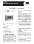
ComfortChoice EDGE®
Installation and Start-Up Instructions
NOTE: Read the entire instruction manual before
starting the installation.
TABLE OF CONTENTS
SAFETY CONSIDERATIONS ......................................... 2
INTRODUCTION ............................................................. 2
INSTALLATION CONSIDERATIONS ........................... 2
INSTALLATION ............................................................. 2
Step 1 - Check Equipment and Job Site ..................... 2
Step 2 - Component Location and Wiring
Considerations ........................................................... 2
LOCATING UTILITY I/O BOARD .................................. 2
LOCATING THERMOSTAT ........................................... 2
WIRING CONSIDERATIONS ......................................... 3
Step 3 - Install Components ...................................... 3
INSTALL UTILITY I/O BOARD ................................... 3
INSTALL THERMOSTAT ............................................ 3
Step 4 - Final Wiring .................................................. 5
UTILITY I/O BOARD WIRING ..................................... 5
WIRING CONSIDERATIONS ....................................... 5
POWER WIRING .......................................................... 5
Step 5 - Understanding Sequence of Operations ..... 5
TEMPERATURE SET POINTS ..................................... 5
HEATING AND COOLING COMFORT SET POINTS . 5
Step 6 - System Configuration ................................... 5
CONFIGURATION ...................................................... 6
To Enter and Exit Configuration Mode .................... 6
While in Configuration Mode .................................. 6
Configuration Options
Option 1—Equipment Type ............................. 6
Option 17—Time Between Stages .................. 8
Option 18—Backlight Configuration .............. 8
Option 19—Outdoor Air Temperature Display
Temperature Adjustment (Offset) ................... 8
Option 20—Serial Communications
Test Mode ...................................................... 8
Option 21—Keypad Lockout ......................... 8
Option 22—Auto Changeover Time ............... 8
Option 26—Minimum Cooling Set Point ........ 8
Option 27—Maximum Heating Set Point ........ 8
Option 33—Single or Two-Piece Installation . 8
Option 99—Reset to Factory Defaults ........... 8
Step 7 - System Startup and Checkout .................... 8
INSTALLER TEST ........................................................ 9
Final Settings ........................................................... 9
Default Schedule ..................................................... 9
OPERATIONAL INFORMATION ................................ 9
Step 8 - Thermostat Programming - Overview ........10
QUICK START ............................................................10
Setting the Clock, Calendar, Daily Schedule
and Vacation Settings ............................................. 10
Programming Comfort Schedules ........................... 10
Programming the Auxiliary Device Schedule .......... 11
Hold Function ......................................................... 11
TROUBLESHOOTING .................................................11
Error Codes .............................................................12
Option 2—Replace Filter Reminder .................. 6
Option 4—Fan (G) On With
W/W1 Selection ................................................ 6
Option 6—Cooling Lockout ............................. 7
Option 8—Auxiliary Heat Lockout
Temperature ...................................................... 7
Option 11—Adjustable Set Point
Deadband .......................................................... 7
Option 12—Smart Recovery ............................. 7
Option 13—Room Air Temperature Offset
Adjustment (Offset) .......................................... 7
Option 15—Auto Mode Availability ............... 7
Option 16—Max Cycles Per Hour .................... 7
This document is the property of Carrier Corporation and is delivered on the express condition that it is not to be disclosed,
reproduced in whole or in part, or used for manufacture by anyone other than Carrier Corporation without its written consent, and
that no right is granted to disclose or so use any information contained in said document.
Carrier reserves the right to change or modify the information or product described without prior notice and without incurring any
liability.
© 2008, Carrier Corporation
11-808-451-01 11/08
This is a Class A product. In a domestic environment this product may cause radio interference in which case the user may be
required to take adequate measure.
1. Install thermostat in non-condensing areas with ambients
between 30°F and 104°F (0°C to 40°C). Install the Utility I/
O board in non-condensing areas with ambients between
-4°F and 158°F (-20°C to 70°C). The auxiliary load
controller can be mounted outdoors if used with the
proper conduit fittings (follow local code requirements).
SAFETY CONSIDERATIONS
Improper installation, adjustment, alteration, service,
maintenance, or use can cause fire, electrical shock, or other
conditions which may cause personal injury or property
damage. Consult a qualified installer, for information or
assistance. The qualified installer must use factory authorized kits or accessories when modifying this product. Refer
to the individual instructions packaged with the kits or
accessories when installing. Follow all safety codes and
wear safety glasses. Read these instructions thoroughly
and follow all warnings or cautions attached to the unit.
Consult local and state building codes and Sheet Metal and
Air Conditioning National Association (SMACNA) for
special installation requirements.
2. The use of separate isolated transformers is required if
the existing system transformer is less than 40 va. The
ComfortChoice system can be powered from the system
transformer in most applications. If the thermostat blanks
or the electronics turn off when the system is active
connect a separate (field supplied) 40 va class 2 isolation
transformer to the 24 Vac and C terminals to power the
electronics.
Recognize safety information. This is the safety alert
symbol ! . When you see this symbol on the unit or in
instructions and manuals, be alert to the potential for
personal injury. Understand the signal words DANGER,
WARNING, and CAUTION. These words are used with the
safety--alert symbol. DANGER identifies the most serious
hazards which will result in severe personal injury or death.
WARNING signifies hazards
which could result in personal injury or death. CAUTION
is used to identify unsafe practices which may result in
minor personal injury or product and property damage.
Note is used to highlight suggestions which will result in
enhanced installation, reliability, or operation.
INSTALLATION
Step 1 — Check Equipment and Job Site
INSPECT EQUIPMENT—File claim with shipping company,
prior to installation, if shipment is damaged or incomplete.
Step 2 — Component Location and Wiring Considerations
! WARNING
PERSONAL INJURY AND UNIT DAMAGE HAZARD
Failure to follow this warning could result in personal
injury and unit damage.
Disconnect power supply before routing wire.
All wiring must comply with national, local, and state
codes.
LOCATING UTILITY I/O BOARD
All wiring is run back to the ComfortChoice Utility I/O
board. Select a location near the furnace or fan coil where
wiring from the thermostat and the equipment itself can
come together easily.
The ComfortChoice I/O board and thermostat are approved
for indoor use only and should never be installed with
these components exposed to the elements. The Utility I/O
board may be installed in any area where the temperature
remains between -4°F and 158°F (-20°C to 70°F), and there
is no condensation. The cover must be installed to prevent
damage from other sources. Do not locate where it will be
accessible to children. Avoid areas in which the sound of
relays energizing on the Utility I/O board may
be an annoyance. The Utility I/O board should be mounted
with the antenna positioned vertically. Wiring access is
likely the most important consideration.
INTRODUCTION
The ComfortChoice System is the industry-leading two-way
verifiable demand management solution. Using this unique
solution, your utility can remotely adjust the operation and
temperature of your air air conditioning or heating system,
for short periods of time during periods of peak energy
usage. You have the Choice to override (cancel) the
adjustment if needed, always keeping you in ultimate
control of your Comfort. ComfortChoice is a two-piece
solution consisting of a programmable thermostat and a
utility I/O board equipped with two-way radio communications. The programmable thermostat offers programming
options that allow you to set different cooling and heating
settings that will change automatically in accordance with
schedules that you set up to fit your particular lifestyle.
•
•
•
Thermostat—Each installation has 1 thermostat. This
is the command center for the system.
Utility I/O board—The Utility I/O board communicates
to the thermostat and provides 24 Vac outputs to the
cooling/heating equipment. The on-board two-way
radio provides system access via wireless radio
frequency communications.
Auxiliary Load Controller—Optional component, not
supplied by Carrier, to facilitate utility auxiliary
curtailment or optionally control a residential device
remotely through combined wireless/internet capability. Device is wired to the Utility I/O board.
! CAUTION
UNIT OPERATION AND SAFETY HAZARD
Failure to follow this caution may damage equipment.
To prevent possible damage to the Utility I/O board, do
not mount on plenum, duct work, or flush against
furnace or air handler.
INSTALLATION CONSIDERATIONS
These instructions cover the physical installation and start
up of the ComfortChoice system.
2
LOCATING THERMOSTAT
The thermostat should be mounted:
• approximately 5 ft (1.5m) from floor.
• close to the center-preferably on an inside wall.
• on a section of wall without pipes or duct work.
The thermostat should NOT be mounted:
• close to a window, on an outside wall, or next to a door
leading to the outside.
• where it will be exposed to direct light and heat from a
lamp, sun, fireplace, or other temperature-radiating
object which may cause a false reading.
• close to or in direct airflow from supply registers and
return-air grilles.
• in areas with poor air circulation, such as behind a door
or in an alcove.
WIRING CONSIDERATIONS
All wiring in the ComfortChoice system may be unshielded.
Ordinary thermostat wire is ideal for all connections. Use 22
gauge or larger for normal wiring. Lengths over 100 ft
should use 20 gauge or larger wire.
Fig. 1 - Locking Tab Location
The thermostat requires 2 conductors.
The connection to equipment (furnace or fan coil) could
require as many as 8 conductors for a multi-stage installation. The optional outdoor air temperature (OAT) sensor
requires 2 conductors. The OAT sensor may be able to be
connected at the outdoor unit using existing wiring.
Cables with excess conductors are acceptable. Cut off or
fold back and tape any unneeded conductors.
Plan the routing of wiring early to avoid possible problems
later on.
Remember all wires converge at the Utility I/O board, so its
location is important.
Step 3 — Install Components
INSTALL UTILITY I/O BOARD
The Utility I/O board is designed so that wires can enter it
from behind, above, or below. Plan wire routing before
mounting Utility I/O Board.
1. Remove cover to access mounting holes (remove the
system cover from the left side first).
2. Mount back plate to wall using screws and wall anchors
provided.
3. Level back plate and tighten screws.
4. Connect included antenna by screwing the threaded end
to the Utility I/O board radio.
INSTALL THERMOSTAT
! CAUTION
EQUIPMENT DAMAGE AND SAFETY HAZARD
Failure to follow this caution WILL damage equipment.
Ensure that the system power is off. Disconnect
existing thermostat wires from existing thermostat and
equipment prior to connecting existing thermostat wires
to the ComfortChoice thermostat.
1. Turn off all power to equipment.
2. If an existing thermostat is being replaced:
a. Remove existing control from wall.
b. Disconnect wires from existing thermostat, one at a
time.
c. As each wire is disconnected, record wire color and
terminal marking.
3
d. New or additional wires may be needed to accommodate added humidity outputs.
e. Discard or recycle old control.
3. Remove mounting plate from back of thermostat display
module by pressing the two tabs on the bottom edge and
pulling away. See Fig. 1. Figure 2 shows the mounting
plate removed from the module.
4. Route wires through large hole in mounting base. Level
mounting base against wall (for aesthetic purposes only
— the display module does not need be leveled for
proper operation) and mark wall through 2 mounting
holes. See Fig. 3.
5. Drill two 3/16-in. mounting holes in wall where marked.
Control may be mounted to a standard junction box, if
desired. Hole pattern on control mounting base matches
junction box mounting holes.
! CAUTION
UNIT DAMAGE AND SAFETY HAZARD
Failure to follow this caution may damage equipment.
Improper wiring or installation may damage the thermostat. Check to make sure wiring is correct before
proceeding with installation or turning on unit.
6. Secure rear plastic mounting base to wall with 2 screws
and anchors provided. Additional mounting holes are
available for more secure mounting if needed. Make sure
all wires extend through hole in mounting base.
7. Adjust length and routing of each wire to reach proper
connector block and terminal on mounting base with 1/4in. extra wire.
8. Connect two wires from the equipment control module to
the display module mounting base, being careful not to
over-tighten the screws. Correct polarity must be
observed when connecting the two wires. If wires are
connected incorrectly, the display module will not
operate.
See Fig. 4 and 5.
9. Connect red wire of the pigtail to V+ RED terminal.
Connect black wire of the pigtail to Vg BLACK terminal.
NOTE: The 2-wire pigtail is not intended to support the
weight of the thermostat. Do not hang the thermostat
from the equipment control module screw terminals.
10. Push any excess wire into wall and against mounting
base. Seal hole in wall to prevent air leaks. Leaks can
affect operation and cause incorrect temperature and/or
humidity measurement.
11. Attach 2-wire pigtail to display module. Pigtail is packed
loose in the box from the factory. Pigtail is attached to
the back of the display module via 2-pin, keyed connector.
12. Reattach display module body to mounting base by first
setting the module on at top of mounting base and then
snapping the bottom corners of display module into
place. See Fig. 6.
4
Step 4 — Final Wiring
UTILITY I/O BOARD WIRING
Bring all Utility I/O board wires together at Utility I/O
board. Make all connections as indicated in Fig. 7.
Figures 9 through 18 show the connection between the
Utility I/O board and the HVac equipment. Select proper
diagram for your equipment and connect accordingly. This
connection will require as few as 4 or as many as 7 conductors.
Fig. 8 - System Wiring
Step 5 — Understanding Sequence of Operations
TEMPERATURE SET POINTS
The ComfortChoice System uses 2 temperature set points,
the higher for cooling and the lower for heating. A minimum
difference of 2°F is normally enforced between heating and
cooling set points, although this value may be adjusted by
the installer. Each set point may be manually adjusted or
controlled by a programmed time schedule established by
the home owner.
It is good practice to mark each wire as the final
connection is made. This will preserve its identity if it is
ever disconnected.
NOTE: Wiring diagrams appear near the end of this
document.
WIRING CONSIDERATIONS
ComfortChoice treats all furnaces as if they were 2-stage.
For single stage equipment, connect to W. The same holds
true for auxiliary heat in fan coils. With any 2-stage furnace,
configure the furnace so that low heat is controlled by W
and high heat is controlled by W and W2 together.
All 2-stage air conditioners and heat pumps need to be
configured so that Y controls low speed and Y and Y2
together control high speed in both heating and cooling.
The ComfortChoice thermostat can also be configured for
Heat Only or Cool Only operation. In these modes a single
set point is used to control a furnace (Heat Only) or an air
conditioner (Cool Only).
HEATING AND COOLING COMFORT SET POINTS
If space temperature is between heating and cooling set
points, then it is said to be “satisfied” with respect to
temperatures. When a space is satisfied, no heating or
cooling is required. When the space is satisfied, there is no
demand and the equipment is turned off. For example, if
cooling set point is 76°F and heating set point is 72°F,
then a space temperature of 73°F is assumed to be satisfactory and no heating or cooling of the space is required.
If space temperature falls below heating set point, then that
space needs to have heat added which will raise space
temperature back to heating set point. For example, if
heating set point is 72°F and space temperature is 70°F,
then space temperature must be raised 2°F in order for the
space to be satisfied. In this case, temperature “heating
demand” for zone is 2°F (72° minus 70°F). Otherwise, if
temperature in a space rises above cooling set point, then
that space needs to have heat removed which will lower
space temperature back to cooling set point. For example, if
cooling set point is 76°F and space temperature is 77°F,
space temperature must be lowered 1°F in order for space to
be satisfied. In this case, cooling demand for space is 1°
(77°minus 76°F).
POWER WIRING
The thermostat is powered by 24 Vac only. The
thermostat requires the 24 Vac (Rh and/or Rc and C
terminals) of the low-voltage transformer to be connected
to it for proper operation. The thermostat will not operate
without these connections. The Rh and Rc terminals are
connected via the PCB breakout jumper. For applications
using a single 24 Vac transformer for power, the breakout
jumper should remain intact. For applications using two 24
Vac transformers, the breakout jumper must be broken
because possible voltage differences between the two
transformers could cause irregular operation or damage to
the thermostat. See Figure 8. For applications using two 24
Vac transformers, one in the indoor unit and one in the
outdoor unit, connect the common wire from each to the C
terminal. Connect R from the indoor unit to the Rh terminal.
Connect R from the outdoor unit to the Rc terminal. Break
the jumper on the circuit board. See Figure 8. The W and
HUM signals are taken from the Rh power and the G signal
is taken from the Rc power. If the control has been installed
in a two-transformer application that is later changed to a
single-transformer installation, the installer must install a
field-supplied jumper between Rc and Rh. Depending on
the installation, up to 14 wires may be required. Installation
as two-piece unit is recommended. Only 2 wires are required
for connection between display module and equipment
control module. These two wires (V+ and Vg) do not
provide ordinary 24 Vac. They carry a combination of
power and communications data that is unique to these
products.
Step 6 — System Configuration
Make sure this step is not left out.
The ComfortChoice thermostat must be configured to
match the type of equipment connected to it. There are
several choices of configuration based on how the user
wants the system to operate. Configuration is done by
setting the equipment type and other options in the
thermostat on power up. Configuration options enable the
installer to configure the thermostat for a particular
installation. Most options are not presented to the homeowner and therefore must be properly set by the installer.
Turn on power to the thermostat.
5
Fig. 7 - System Wiring
Configuration Options
OPTION 01 — EQUIPMENT TYPE — Determines the
control method of the thermostat. It should match the type
of equipment used. Equipment Types are as follows: H2 Two speed Heat Pump with a fan coil, HP - Single speed
Heat Pump with a fan coil, A2 -Two speed AC with a
furnace, AC -Single speed AC with a furnacel, H - Heat only
system. Furnace or fan coil only; no outdoor unit, C - Cool
only system. Outdoor AC unit with an indoor fan coil with
no strip heaters.
OPTION 02 — REPLACE FILTER REMINDER — Selects
the hours of fan operation (heating, cooling, or fan) before
CHECK FILTER icon is displayed. With OF selected, the
icon will never come on, disabling this feature. Time
selection can range from 800 to 7200 hours by selecting
numbers 1 through 9. The time is 800 hours times the
number selected. Default is 1 (800 hr). Recommended
selections are disposable filter-800 to 2400 hrs, media filter2400 to 3200 hrs, or electronic air cleaner-1600 to 2400 hr of
fan operation. For higher efficiency filter, consult filter
literature.
OPTION 04 — FAN (G) ON WITH W/W1 SELECTION
— Determines whether fan (G) output is to be On or Off
when any W (furnace or strip heat) output is On. Most
furnaces and fan coils manage their own blowers and do
not require a separate G signal. For these applications,
At power up the thermostat displays all segments for a few
seconds. Follow the instructions below to enter configuration mode and set the configuration options.
CONFIGURATION
To Enter and Exit Configuration Mode — Press
and hold the FAN button for approximately 10 seconds.
The display module will now be in Configuration mode. The
module will automatically exit this mode if no button is
pressed for 3 minutes. Pressing the DONE button will exit
Configuration mode immediately.
While in Configuration Mode — The option number is
displayed in the lower right corner of the display in the heat
set point location and the configuration setting is displayed
in the cool set point location. A box will surround the
option number. The MODE button is used to move the box
between the two displayed values or the softkeys below
the values may also be used. The value inside the box is
changed by using the UP or DOWN button. All changes
made are saved at the time of selection and will be saved in
the event of the 3-minute timeout or when installer exits
from configuration menu. See the table on the next page for
the list of configuration options. Each option is described
below.
6
Option
Number
select Off. Some auxiliary heaters require a separate G signal
to turn on the blower. In this case, select On. Allowable
selections are On and OF (off). Default is OF (off).
OPTION 06 — COOLING LOCKOUT — Disables cooling
if outdoor temperature is below 55°F. It requires an outdoor
temperature sensor. Setting is not available if outdoor
sensor is not connected. Set to OF (off) to allow cooling
below 55°F. Set to On to prevent cooling below 55°F. If the
compressor is already operating and the outdoor air
temperature drops below 55°F, the compressor will continue
to operate until the cooling cycle has completed. Default is
OF (off). If this selection has been set to On and the
outdoor air sensor fails, an outdoor air temperature error
will be displayed and this configuration will be available for
the installer to change the setting from On to Off.
OPTION 08 — AUXILIARY HEAT LOCKOUT TEMPERATURE SETTING — This option is only available on
heat pump systems with a valid outdoor temperature sensor
connected. Available settings are: Off, 5, 10, 15, 20, 25, 30,
35, 40, 45, 50, 55. OF (off) - function is disabled. Auxiliary
heat is allowed to operate whenever sufficient demand for
heat is available. 5-55°F - Outdoor air temperature above
which the auxiliary heat is not allowed to operate (unless
MODE is set to Emergency Heat). Default is OF (off).
OPTION 11 — ADJUSTABLE SET POINT DEADBAND
— This option is not available on Heat Only or Cool Only
systems. The selection allows the installer to choose the
number of degrees between the heating and cooling set
points. Higher numbers provide less precise temperature
control but save energy, Lower numbers provide comfort
with more energy use. Allowable selections are 1 to 6°F.
The default is 2°F.
OPTION 12 — SMART RECOVERY — Smart Recovery is
a function that transitions the room to the next programmed
set points as energy efficiently as possible. OF (off) means
set points change precisely at setback recovery time. 30, 60,
or 90 selects the number of minutes before next programmed period that recovery starts. Recovery takes place
smoothly during the selected recovery time, ending at the
recovery time and temperature which is programmed.
Allowable selections are OF (off), 30, 60, and 90. The
default is 90.
OPTION 13 — ROOM AIR TEMPERATURE OFFSET
ADJUSTMENT (OFFSET) — Selects the number of
degrees to be added to the displayed temperature to
calibrate or deliberately miscalibrate the measured room
temperature. The range is from –5 to +5°F. The default is 0.
OPTION 15 — AUTO MODE AVAILABILITY — This
option is not available on Heat Only or Cool Only systems.
Allows the installer to select auto changeover mode in
addition to heat and cool. It allows the thermostat to
automatically change between heating mode and cooling
mode when sufficient demand for heating or cooling exists.
On - Auto mode is available. OF- Auto mode is not
available. The default is On.
OPTION 16 — MAX CYCLES PER HOUR — This
selection limits the number of cycles per hour that the
thermostat allows the system to operate. Selections are 2, 4,
6. 2 - Heating and cooling outputs will be energized no more
than 2 times per hour. When an output is energized, it will
Configuration
01
Equipment Type
02
Replace Filter Reminder
04
Fan (G) with W Output
06
Cooling Lockout
(only available with OAT
sensor)
08
Aux Heat Lock Out Temp
(only available on HP
systems with OAT sensor)
11
Adjustable Setpoint
Deadband
12
Smart Recovery
13
Room Air Temp Display
Adjustment (Offset)
15
Auto Mode Availability
16
Cycles per Hour
17
Time between Stages
18
Backlight Configuration
19
OAT Display Adjustment
(Offset)
20
Radio Registration or Self
Test
21
Keypad Lockout
22
Auto Changeover Time
26
Min Cooling Setpoint
27
Max Heating Setpoint
33
One or Two Piece
Installation
99
Reset to Factory Defaults
7
not be energized again for 30 minutes. 4 - Heating and
cooling outputs will be energized no more than 4 times per
hour. When an output is energized, it will not be energized
again for 15 minutes. 6 - Heating and cooling outputs will
be energized no more than 6 times per hour. When an
output is energized, it will not be energized again for 10
minutes. The default is 4.
OPTION 17 — TIME BETWEEN STAGES — This
selection is only available for heat pump systems. This
determines the minimum number of minutes of equipment
operation on the highest compressor stage before allowing
the transition to auxiliary heat. Available selections are 10,
15, 20, and 25 minutes. The time between stages of low
speed and high speed of any individual piece of equipment,
such as low speed and high speed compressor or fan coil
stages, will be fixed at 10 minutes. The default is 15 minutes.
OPTION 18 — BACKLIGHT CONFIGURATION —
When set to OF (off), the backlight will be lit for 10 seconds
after a button is pressed. After 10 seconds of no button
presses, the backlight turns off. When On, the backlight
will normally be dim in appearance. The backlight brightness becomes brighter when a button is pressed. After 10
seconds of no button presses, the backlight will return to
the dimmer level until another button press occurs. The
range of brightness is 1 through 5 with 5 being full brightness. The default is 3.
OPTION 19 — OUTDOOR AIR TEMPERATURE DISPLAY ADJUSTMENT (OFFSET) — This selection allows
the calibration or deliberate miscalibration of the outdoor air
temperature sensor reading. The selection ranges from –5
to +5 F. The default is 0.
OPTION 20 — SERIAL COMMUNICATIONS TEST
MODE — Changing the display from OF to SE using the up
or down button will initiate a wireless message to facilitate
end to end testing of the wireless connection. The thermostat will communicate to the Utility I/O board to send a
wireless message to the server. The Utility I/O board will
monitor the status of the message and send this information back to the thermostat. When a test message is in
progress, “SE” will be shown in the room temperature
display followed by "LI". The clock display will increment
indicating how long the test has been in progress. If the
test message was successfully sent and received by the
wireless connection, “PAS” will be displayed in the clock
location. If the message was not successfully sent and
received, F1 or F2 will be displayed in the clock location.
(F1—cannot send message; F2—message sent, no reply.)
The installer can cancel the self test at any time by pressing
the up/down button and changing the room air display to
OF. To initiate another test, the setting must be set back to
SE. Allowable selections are OF (off) and SE (serial test).
Use UP or DOWN button to select between OF (off) and SE
(serial test). The default is OF (off).
OPTION 21 — KEYPAD LOCKOUT — This selection
allows the installer to limit access to the keypad. Selections
are OF (off), 1, 2, 3. When set to OF (off), the user has full
access to the keypad. When set to 1, the user has access to
modify set points (within the set point limits of OPTION 26
and OPTION 27) and time of day and the calendar. The
occupied button is functional. When set to 2, the user has
access to change the set points only. The occupied button
is functional. When set to 3, the entire keypad is locked.
When a button is pressed, the backlight will turn on but
none of the operating parameters will be changed. When
the keypad lock selection is turned on, the padlock icon will
be displayed. To unlock the keypad, press and hold the UP
and DOWN buttons simultaneously for five seconds.
When the keypad is unlocked, the padlock icon will turn
off. The keypad will remain unlocked for two minutes after
the last button press. After two minutes with no button
presses, the keypad will lock again. The keypad will not
lock in the software configuration mode or in the installer
test mode. The default is OF (off).
OPTION 22 — AUTO CHANGEOVER TIME — This
selection is not available on Heat Only and Cool Only
systems. The system must have no demand in the current
mode for the selected number of minutes before the AUTO
mode will be allowed to change between heating and
cooling or vice versa. Allowable selections are 5, 10, 15, 20,
25, 30 minutes. The default is 30.
OPTION 26 — MINIMUM COOLING SET POINT —
This selection allows the installer to configure the minimum
cooling set point that the user is allowed to set. The range
takes into account the value of the adjustable deadband
Option 11. The range is 50°F (plus the adjustable
deadband) to 90°F. The default is 52°F (based on the
adjustable deadband default of 2).
OPTION 27 — MAXIMUM HEATING SET POINT —
This selection allows the installer to configure the maximum
heating set point. The range is based on the adjustable
deadband value Option 11. The range is 50°F to 90°F minus
the deadband. The default is 88°F (based on the adjustable
deadband default of 2).
OPTION 33 — SINGLE OR TWO-PIECE INSTALLATION
— This option should be left at the default setting of 1P
(single piece installation), which is the required setting for
use with the 2-way radio. 2P (two piece installation) is for
future use. The default is 1P.
OPTION 99 — RESET TO FACTORY DEFAULTS — Use
this capability to reset the control to “out of the box”
conditions.
IMPORTANT: All configuration settings, program
settings, clock, and calendar settings which have been
manually entered will be lost and reset.
8
When this option is selected, the number 99 will appear in
the cool set point location (left) and the number 10 will
appear in the heat set point location (right). To perform the
reset, first use the MODE button to move the box from the
99 to the 10. Press and hold the DOWN button. The 10 will
start counting down toward zero. If the DOWN button is
kept pressed until the count reaches zero, the reset will be
performed. When the value reaches zero, the heat set point
will display “-.” The cool set point will display “-” and the
air temperature will display “Fd.” When the factory defaults
have been restored, the thermostat will act as if power was
cycled and return to normal operation. If the DOWN button
is released early, the number will return to 10 and the reset
will not occur. After the reset, the installer should enter the
installer configuration to verify that it is configured for the
thermostat application.
cycle by simultaneously pressing the FAN button and the
UP button. It is not active in the installer setup mode.
Cycle Timer
Based on the selection of 2, 4, or 6 cycles per hour, this
timer is set to 30, 15, or 10 minutes. This time must elapse
from the start of one cycle before another cycle can be
defeated for one cycle by simultaneously pressing the FAN
and UP buttons.
Ten-Minute Staging Timer
In multistage heating or cooling this timer prevents any
higher stage from coming on until the previous stage has
been on for 10 minutes. When staging between compressor
and electric heat or between compressor and furnace heat,
the time is configurable. The timer is configurable via
Option 17. This timer is overridden if temperature error is
greater than 5°F (usually due to a large change in desired
temperature) and equipment stages up in 60 second
intervals.
Three-Minute Minimum On Time
When a cooling or heating stage is turned on, it will remain
on for at least 3 minutes. These timers are canceled when
set points are changed.
Heat/Cool Set Point Difference
A minimum difference of 1°F and 6°F is enforced between
heating and cooling desired temperatures (set points). This
deadband is maintained by allowing one set point to
“push” the other to maintain the required minimum difference. This difference is adjustable via configuration Option
11.
Step 7 — System Startup and Checkout
INSTALLER TEST
The thermostat is designed with a built-in installer test
capability. It allows easy operation of equipment without
delays or set point adjustments to force heating or cooling.
To enable installer test mode, press and hold the FAN
button for 15 seconds. The control will enter configuration
mode. Continuing to hold the FAN button will cause the
thermostat to enter installer test mode. IN ST will be
displayed in the heat and cool set point location. Pressing
the MODE button will change the system operating mode
to test the heating and cooling equipment. The Auto mode
is not available during installer test mode. If no buttons are
pressed for 15 minutes, the installer test mode will be
terminated. Pressing DONE at any time will exit installer test
mode.
HEATING — The first stage of heating will be energized for
3 minutes, then the first and second stages will turn on for
an additional 3 minutes. During the first stage of heating,
the HEAT ON icon will be displayed. During the second
stage of heating, the “2” next to the “On” will be displayed.
COOLING — Installer test for cooling is the same as
described for heating above. The COOL ON will be
displayed during cooling in installer test mode. When the
mode is set to “em heat,” the auxiliary heat will turn on for 3
minutes. The clock display will count down from 180 to 0
during this test.
TO TEST FAN — Pressing the FAN button will switch the
triangle icon between AUTO and ON. While ON is displayed, the G output will be energized, turning the fan on.
Allow up to 10 seconds after the button is pressed for the
fan to turn On and Off. On some fan coils, the fan continues
to operate for 90 seconds after the G sifnal is removed.
TO TEST AUXILIARY RELAY (IF EQUIPPED) — Use the
MODE button to set the system to OFF and then press the
SET button to toggle the auxiliary relay. The AUXILIARY
icon will be displayed when the relay is energized. When
the mode is set to HEAT or COOL during the installer test,
the auxiliary relay will be de-energized.
Final Settings
Be sure to press DONE to exit installer setup mode. If the
system is to be left in operation after installation is complete, use MODE button to select between HEAT, COOL,
AUTO, or EM HEAT to provide desired operation.
Default Schedule
If the programmed schedule is to be used, make sure the
triangle icon appears before the FOLLOW SCHEDULE icon.
The default schedule is shown in Table 1. Pressing the
Schedule button will cycle the triangle icon through the
FOLLOW SCHEDULE, HOLD and VacATION selections. If
fixed temperatures are desired, use SCHEDULE button to
turn on the triangle icon next to HOLD. This will maintain
set points, not allowing them to change with programmed
schedule. Use the FAN button to select between AUTO
(fan on only with equipment) and On (fan on continuously)
fan modes.
OPERATIONAL INFORMATION
Five-minute Compressor Timeguard
This timer prevents the compressor from starting unless it
has been off for at least 5 minutes. It can be defeated for 1
S C H E D U LE
HEAT
COOL
Wake 6:00 AM
68°F
78°F
Day 8:00 AM
60°F
85°F
Evening 5:00 PM
68°F
78°F
Sleep 10:00 PM
60°F
82°F
Table 1 – Default Program Schedule
Equipment On Indicators — When cooling equipment
is on, a COOL ON icon is displayed. While cooling
equipment operation is delayed by the time guard or cycle
timer, COOL ON will flash. The same is true for HEAT ON
icon. During second stage compressor operation a “2” will
be displayed with the HEAT ON or COOL ON icon. When
the W is energized in a heat pump or emergency heat is
available the “AUXILIARY HEAT ON” icon will be
displayed.
Auto Changeover
When the auto changeover mode is selected, a change from
heat to cool or cool to heat will not occur until an opposite
mode demand has existing for the number of minutes
specified by configuration Option 22. If the set point is
changed, the specified time requirement is deleted.
Emergency Heat Mode
When the system is configured for a heat pump and
EHEAT mode is selected, Y outputs are disabled and W
outputs only are used for heat.
9
Table 2 – Outputs vs. Stages
bottom center of the screen. Use the softkeys to move the
PIN Number Display
box around the digits to be set and use the UP or DOWN
The wireless modem PIN number may be displayed by
button to change the setting.
pressing the SET button and then pressing and holding the
To set the daily schedule:
soft key below the Hours value for 10 seconds until the
Pressing the SET button will cycle through ...clock, ...daily
display goes blank. The PIN number will then be displayed
schedule and ...vacation settings. When changing daily
across the room air, cool set point and clock locations. The
schedule settings, the softkeys are used to set the days,
thermostat will return to normal operation after 15 seconds.
period times, heating set points, and cooling set points.
NOTE: The PIN number will not be displayed if in software
The UP and DOWN buttons are used to change the setting
configuration, installer test or programming modes.
with the box around it. All program periods (WAKE, DAY,
Other Messages
EVE, and SLEEP) must occur within the same 24-hour
HEAT ON, COOL ON — The HEAT ON and COOL ON
period.
icons, which are located under the two set point displays,
Vacation schedule: When changing Vacation settings, the
indicate when cooling or heating equipment is actually
softkeys are used to choose the selection to be adjusted
operating. When the icons flash, equipment is waiting to
and the UP or DOWN button is used to change the setting.
come on but is being held off by compressor timeguard or
A Vacation selection is available specifically for times when
cycle timer.
the space will not be occupied for an extended period.
The triangle icon appears before the fan mode ON icon.
Vacation mode has an automatic hold, meaning that set
During an unoccupied mode (DAY, SLEEP) the fan
points are not affected by the programmed schedule.
selection will be allowed to change from AUTO to ON, but
Vacation mode is active for a specified period of time. While
when ON is selected and the equipment is not running, the
in Vacation mode, the system provides temperature
triangle icon will appear before the ON icon. This is a
protection for the space in the selected mode, but not
feedback to the user that the fan is not running because the
comfort. When Vacation mode is active, the triangle icon
current period is unoccupied and the equipment is not
will be displayed before the VACATION in the upper left
running.
corner of the display.
Outputs vs. Stages
Vacation Set Points — A default set of temperature and
Table 2 above lists the active outputs for each stage of
humidity set points are active in Vacation mode. They are
each possible system configuration. G is not shown. For 1adjustable by the user and are used exclusively for Vacastage furnaces and auxiliary heat, connect to W and leave
tion mode. They are remembered from one Vacation
W2 open. For single speed compressors, connect to Y and
selection to the next. See Table 3 below for default Vacation
leave Y2 open.
values.
Step 8 - Thermostat Programming - Overview
MODE
AUTO
QUICK START
This quick start procedure provides an overview of
Fan
Auto
programming in order for you to begin to use your system.
For the best comfort and energy-saving results and detailed
Heat Set Point
55°F
thermostat operating instructions, we recommend that you
read through the ComfortChoice Edge Owner’s Manual,
Cool Set Point
85°F
which is included in the box along with your thermostat,
Table 3 - Vacation Set Points Default Values
and set up the system to match the end-user’s specific
schedule and comfort requirements.
Programming Comfort Schedules
Setting the Clock, Calendar, Daily Schedule,
The following is a brief overview of how to access and
and Vacation Settings
program schedules in your new system. For additional
The thermostat communicates wirelessly with a communicainformation, we also recommend that you read and follow
tion network and it automatically obtains the current time
the programming information provided in the
and date from the communication network. In the event of
ComfortChoice Edge Owner’s Manual that is included in
loss of network communication, you can manually set the
the box with the thermostat.
time and date by following the instructions below.
To set the clock:
Press and release the SET button until ...clock is displayed
in the left center of the display along with the time at the
10
During the programming process, you will have access to 4
program time periods; WAKE, DAY, EVE, and SLEEP. You
will be able to select program start times and the heat/cool
set points for each time period.
1. Decide on a program schedule that you desire. Table 1
is an example of what already exists in the thermostat as
the Energy Star recommended settings.
2. Press and release the SET button repeatedly until the
screen displays ...daily schedule in the center of the
screen. The list of the days of the week will be displayed on the left.
3. Press and release the soft button under the days of the
week until the day or days you want to program are
displayed.
4. Look at the column to the right of the days of the week.
This column displays the time period (wake, day, eve,
or sleep ). To set the wake time, press and release the
soft button under the time period until wake is displayed, press the soft button under the hour or minute,
and then press the up or down button to change the
time.
5. Set the heating set point temperature for that time
period by pressing and releasing the soft button under
the heat set at: temperature. Then press the up or down
button until the desired heat set point temperature is
displayed.
6. Set the cooling set point temperature for that time
period by pressing and releasing the soft button under
the cool set at: temperature. Then press the up or down
button until the desired cooling set point temperature is
displayed.
7. Repeat this process for each of the three remaining time
periods - day, evening and sleep - by first pressing the
soft button under the time period to select it. Then use
the soft buttons and the up or down button to change
the start time, the heating set point, and the cooling set
point.
8. To set the schedule for another day, press and release
the soft button under the days of the week until the day
or days you want to program are displayed.
9. Repeat steps 4 through 7 to program each day.
10. Press the DONE button when complete.
Programming the Auxiliary Device Schedule
In addition to the primary program schedule, the I/O board
provides an auxiliary relay for auxiliary control capability.
The auxiliary device program schedule allows the user to
automatically control an auxiliary residential device with 4
program periods throughout the day (wake, day, eve,
sleep). Each period allows the user to set the start time and
the desired state of the auxiliary device (either ON or OFF)
for that period. The program schedule for weekdays and
weekends can be set independently.
1. Decide on a program schedule that you desire. Table 4 is
an example of an auxiliary program schedule.
2. To begin programming the auxiliary schedule, press and
hold the SET button for at least 10 seconds. When
auxiliary programming mode is active the display will
show the icon AUXILIARY and the current program
period (wake, day, eve, sleep) will be displayed in place
of the room temperature display.
3. Press and release the soft key below the days of the week
until the weekday icons (Mo Tu Wed Thur Fri) are
displayed.
4. Press and release the soft key below the period (wake,
day, eve, sleep) until the wake period is displayed.
5. Press the soft key below the hour and then set the
desired start hour for the wake period by pressing the UP
or DOWN button.
6. Press the soft key below the minute and then set the
desired start minute for the wake period by pressing the
UP or DOWN button.
7. Press the soft key below the relay state (either “On” or
“OF”) and then press the UP or DOWN button to toggle
the relay state for the current period On or OF (Off).
8. Press the soft key below the wake program period to
change to the next period (day). Repeat steps 5 through
7 to set the start time and relay state for the day period.
9. Use the soft key below the program period to select the
next period and repeat the procedure.
10. After the 4 (wake, day, eve, sleep) weekday periods are
programmed, press the soft key below the day of the
week to display the SAT and SUN icons. Repeat the
procedure to program the weekend auxiliary schedule.
11. Press the DONE button to exit programming mode.
Hold Function
When the HOLD function is active you can change your
programmed temperature settings and hold the temperature
at a specific setting without the temperature changing
during the next programmed period.
1. Open the thermostat door.
2. Press and release the SCHEDULE button located at the
top of the display until the triangle icon appears before
the HOLD icon.
3. The set point temperature will be displayed in the lower
right. To change the set point temperature, press the up
or down button. The temperature will stay at the new
setting until you release the HOLD (see Step 5 below).
4. To change the heating set point temperature when the
cooling temperature is displayed - and vice versa - press
and release the MODE button located at the top of the
display until the triangle icon appears before the desired
mode - heat or cool. Then press the up or down button
to change the set point temperature.
5. To return the temperature to the pre-set level for that time
period (release the HOLD), press the SCHEDULE button
until the arrow moves to FOLLOW SCHEDULE.
6. Close the door.
TROUBLESHOOTING
If the thermostat display does not power up after power is
applied, check the Rc/Rh and C terminals for 24 Vac. If 24
Vac is present, check the voltage between Vg and V+. This
voltage will be approximately 12 to 20 Vdc. If voltage is
present, check the polarity to make sure it is wired correctly.
The display will not power up if polarity is reversed. Table 2
can be used as a troubleshooting tool for determining
which outputs will be active for a particular configuration
and each operating mode.
11
Error Codes
“--” — Thermistor failure
Temperature sensing element in the thermostat cannot
properly read room temperature. All outputs (except fan,
if set to on) will turn off. The thermostat must be replaced. In the case where the installer has selected to
average the local sensor and the remote sensor, the
display will alternate between “--” for the failed sensor
and the temperature sensed by the working sensor every
10 seconds. The thermostatl will operate from the
temperature sensed by the working sensor.
E1 — The thermostat and the I/O board cannot communicate via two-wire connection.
E4 — Internal memory failure. When this error is present
and power is cycled to the thermostat all of the installer
configurations, program schedule settings and user
settings will be factory default values. Replace the
thermostat.
I/O Board Error Codes —
Error codes for the I/O board are indicated by the flash rate
of the on board LED. The slow flash rate is the first digit,
and the fast flash rate is the second. During normal
operation the flash rate of the LED will be 1 second on, 1
second off.
23—Flash Memory Error. Replace the I/O Board.
25—EEProm (Memory) Error. Replace the I/O board.
27—RAM Memory Error. Replace the I/O Board.
32—Device out of range. Check antenna connection.
34—No communications with thermostat. Check connections between the I/O board and the thermostat.
36—No communications with the Radio. Check cable
connection between the thermostat radio and the I/O
board.
PROGRAM
PERIOD
TIME
AUX
RELAY
Wake
4:00 AM
On
Day
9:00 AM
Off
Eve
3:00 PM
On
Sleep
11:00 PM
On
Table 4 - Auxiliary Device Program Schedule
12
Table 5 - Temperature/Ohm Relationship
13
Figure 9 - 1-Stage Boiler with 1-Stage Air Conditioner
Figure 12 - 1-Stage Furnace with 2-Stage Air Conditioner
Figure 10 - 1-Stage Furnace
Figure 13 - 2-Stage Furnace with 1-Stage Air Conditioner
Figure 11 - 1-Stage Furnace with 1-Stage Air Conditioner
14
Figure 14 - Typical fan Coil with 1-Stage Air Conditioner
Figure 15 - 2-Stage Furnace with 2-Stage Air Conditioner Figure 16 - Typical Fan Coil with 2-Stage Air Conditioner
Figure 17 - Typical Fan Coil with 2-Stage Heat Pump with
Reversing Value Active in Cooling
15
Figure 18 - Typical Fan Coil with 1-Stage Heat
Pump with Reversing Valve Active in Cooling
16