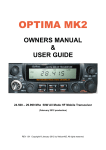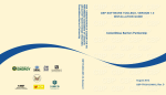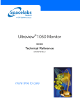
1
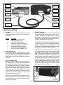
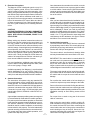
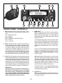
MAGNUM 357DX
OPERATING MANUAL
Copyright © 2000 by Magnum International. All rights reserved.
TABLE OF CONTENTS
Introduction ......................................................................................................... 4
Limited Warranty ................................................................................................. 5
Installation ...................................................................................................... 6 - 7
Front Panel Controls..................................................................................... 8 - 10
Other Features ................................................................................................... 10
Specifications .....................................................................................................11
Contact Information ............................................................................................ 12
-3-
INTRODUCTION
Congratulations on your purchase of a Magnum 357DX 10 meter FM/SSB/AM transceiver. The 357DX is
designed to provide years of enjoyment and trouble-free service. There are many features and functions
designed into this transceiver. To ensure that your investment is enjoyed to its fullest extent, please take a
few moments and thoroughly read this manual.
The Magnum 357DX is a microprocessor controlled, user programmable radio combining both high RF performance with a user-friendly environment. The 357DX is a 12 volt DC, HF transceiver designed for mobile
use. The transceiver is configured in two separate components; a high powered RF deck and a compact
sized control deck. The two decks are linked via a proprietary control cable. As cabin space diminishes in
modern vehicles, this concept helps create a wider variety of installation options. Although engineered with
mobile use in mind the 357DX, with the addition of a high quality 50-amp power supply, may be easily
adapted for fixed station operation.
The control deck utilizes the latest in surface mount production techniques. This keeps the size of the unit to
a minimum without sacrificing any of the advanced circuits required for today’s high performance radios. The
RF deck incorporates a pair of bi-polar RF transistors in push-pull operation. The devices are continuously
biased class A/B using Magnum’s exclusive fully regulated bias circuit. This means unsurpassed audio quality in SSB and AM modes.
Some of the features of the 357DX are; an advanced design liquid crystal display that provides the operator
with a full visual account of the transceivers operating status, automatic frequency scanning from either the
front panel or microphone, memory storage of your favorite frequencies and modes, programmable frequency resolution of either 1 kHz, 10 kHz or 100 kHz, and split frequency operation for repeater use. These
are just a few of the features that make the 357DX a pleasure to own and operate.
IMPORTANT: The Magnum 357DX is designed for amateur radio use. If the transmitter is operated in the
United States or within it’s territories a licensed amateur radio operator must be present at the station. The
minimum license class to operate 10 meter phone is Novice/Technician. If you are studying for your license
and want to familiarize yourself with the operation of the radio, the receiver may be operated with or without
a licensed operator present. For more information regarding FCC licensing, contact your nearest amateur
radio dealer, or for complete details contact the American Radio Relay League.
American Radio Relay League (ARRL)
225 Main Street
Newington, CT 06111
Telephone 860-594-0200
Facsimile 860-594-0259
http://www.arrl.org
-4-
LIMITED WARRANTY
Magnum International warrants this product to be free of defects for a period of one (1) year from the original
date of purchase. This warranty is non-transferable. This limited warranty is subject to repair or replacement
of defective components only. This warranty is void if the radio has been tampered with or misused.
IMPORTANT: RETAIN YOUR SALES RECEIPT
The enclosed warranty registration form must be filled out and mailed along with a photocopy of your sales
receipt within 15 days from the purchase date. If the warranty registration form and copy of your sales receipt
are not received the radio is not covered under warranty. Please fill out the enclosed warranty registration
form and send it along with a copy of your sales receipt to:
Magnum International
PO Box 445
Issaquah, WA 98027
Registering your 357DX with Magnum provides several benefits:
1) Validates your warranty.
2) Entitles you to free updates and information regarding your radio and new accessories for your radio.
3) Provides possible recovery of lost or stolen radios through our serial number tracking database.
4) Receive your free Magnum logo baseball cap within 30 days after registering.
-5-
External
Speaker Jack
RF Deck
(rear panel)
Control Deck
(rear panel)
Antenna
Connector
Control Cable
D-SUB Jack
Control Cable
D-SUB Jack
Control Cable
D-SUB Plug
Control Cable
D-SUB Jack
Power Lead
Red (+)
Black (-)
Control Cable
(9 Feet)
INSTALLATION
1. Contents
Unpack and inspect your Magnum 357DX for missing
or damaged components. Your 357DX includes the following items:
Quantity
1
1
1
1
1
1
1
1
4. RF Deck Mounting
When mounting the RF deck, choose a location that is
close to the antenna and the power source. This will
maximize RF performance. Make sure that there is
ample space around the RF deck for air circulation and
for the cabling. Do not pinch, or bend sharply, the control cable, coaxial cable or power cable.
Description
Magnum 357DX Control Deck
Magnum 357DX RF Deck
9 Foot (2.8m) Control Cable
Microphone with Up/Down Controls
Control Deck Bracket with Hardware
RF Deck Bracket with Hardware
Microphone Hanger with Hardware
Manual, Schematic, Warranty Form
The RF deck may be mounted to hang from the bracket
(as shown below) or rest on the bracket (as in floor
board mountings). The top mounting channel is used
to hang the RF deck and the bottom channel is used in
floor board mountings. See illustration below.
First, attach the mounting bracket to the vehicle with
the provided sheet metal screws. Make sure the bracket
is extremely secure and stable - the RF deck is heavy!
Next, loosely attach all hardware to the bracket. Attach the hardware as shown in the illustration below,
with the rubber washer between the square nut and
the bracket (rubber washer is not shown in illustration).
Slide the RF deck onto the bracket so that the square
nuts enter the appropriate mounting channel. The rubber washers should be between the bracket and the
RF deck to avoid scratching. Once in position, tighten
the screws to secure the RF deck.
2. Microphone Hanger
The microphone hanger may be attached to the side
of the control deck, or any other convenient location.
Use the provided screws to attach the microphone
hanger either vertically or horizontally to the side of the
transceiver.
3. Control Deck Mounting
When attaching the control deck mounting bracket to
the vehicle, choose a location that will provide easy
access to all front panel controls and air circulation to
the rear panel. When selecting a mounting location,
make sure that there is ample space behind the control deck for the control cable. Do not pinch, or bend
sharply, the control cable. Do not install the control deck
in any compartment that restricts airflow and do not
install the control deck in a location that interferes with
the safe operation of the vehicle.
Attach the mounting bracket to the vehicle first then
mount the control deck to the bracket. If the rear panel
is not accessible you may want to attach the control
cable prior to mounting.
Top Mounting
Channels
-6-
Bottom Mounting
Channels
5. Electrical Connections
The Magnum 357DX is designed to work on any 13.8
volt DC, negative ground, source. The condition of a
vehicle’s electrical system can affect operation. A low
battery, worn generator/alternator, or poor voltage regulator will seriously impair the performance of the transceiver. Any of the above conditions could result in a
high level of receiver noise generation or a substantial
loss of the transmitter’s RF output. Make sure that all
of these components of your vehicle’s electrical system are in good condition prior to installing the transceiver.
Once the antenna is mounted on the vehicle, route the
coaxial cable so that it is not next to any power cables
or vehicle cables. Connect the PL-259 to the antenna
connector on the rear panel of the RF deck. Make sure
that the cables does not interfere with the safe operation of the vehicle.
7. VSWR
After you have determined that the installation is correct and the radio is operational, it is important to determine the antenna system’s VSWR (voltage standing wave ratio). Prior to taking any measurements make
sure the SWR bridge (meter) is in good working order
and is calibrated.To ensure your radio is performing
properly the VSWR should never exceed 1.5 to 1. Never
transmit on any antenna system where the VSWR exceeds 1.8 to 1. This will stress the output stage and
could destroy the RF transistors; this type of misuse
and failure is not covered under warranty.
CAUTION!
VOLTAGE EXCEEDING 15 VDC WILL DAMAGE THE
RADIO. MEASURE VOLTAGE AT BATTERY TERMINALS, WITH VEHICLE RUNNING, PRIOR TO INSTALLATION!
Before making any electrical connections make sure
the AF gain (volume) control on the control deck is in
the “OFF” position. The 357DX power lead is located
on the RF deck and must be connected directly to the
vehicle’s battery. Connecting directly to the battery has
several benefits, the first of which is to maximize RF
output. Secondly, the battery is a very large capacitor
and will help eliminate certain types of ambient and
vehicle noise. Thirdly, the Magnum 357DX draws upwards of 40 amps and most vehicles’ electrical systems can not handle this amount of current.
8. Control Cable Connection
The 357DX control deck and RF deck are connected
by a proprietary control cable. This control cable is approximately 9 feet long and features two D-SUB connectors with 13W3 pin arrangements.
The control cable is non-directional, therefore either
end may be attached to the control deck or RF deck.
IMPORTANT: The control cable is a tuned cable! Do
not under and circumstances attempt to shorten or
lengthen the cable. Do not cut the cable, or unsolder
any of the wires inside the D-SUB connectors. If a
longer or shorter cable is required for your installation,
contact Magnum International for more information.
For most installations, additional power cable will be
required. When running additional power cable, make
sure to use 8 gauge, or larger, cable.
Available separately from Magnum is a professional
vehicle installation kit for your 357DX, model VI-12.
The VI-12 kit includes everything (including extra power
cable) for a safe and professional vehicle installation.
The control cable should only be routed through safe,
dry locations that do not interfere with the operation of
the vehicle and do not put the control cable at risk of
damage.
6. Antenna Connection
The transceiver will operate using any standard 50ohm ground-plane, vertical, mobile whip, long wire or
similar antenna. The antenna should be rated at 500
watts PEP minimum. A standard SO-239 type antenna
connector is located on the rear panel of the RF deck.
Connection is made using a PL-259 and high grade
coaxial cable (RG213, RG58A/U or Mini RG-8 is recommended).
Do not allow the control cable to be bent sharply or
routed in a way that may cause damage to the cable.
Do not coil excess control cable! Coiling the cable creates an inductive reaction and can create high standing waves under certain operating conditions. Plan your
installation carefully to avoid having excess control
cable.
Do not put force or strain on any part of the control
cable or connectors.
A ground-plane antenna provides greater coverage and
is recommended for fixed station-to-mobile operation.
For point-to-point fixed station operation, a directional
beam antenna operates at greater distances even under adverse conditions. A non-directional antenna
should be used in a mobile installation; a vertical whip
is best suited for this purpose. The base loaded whip
antenna normally provides effective communications.
For greater range and more reliable operation, a full
quarter wave whip may be used.
After routing the control cable, carefully push the DSUB connectors into the jacks on the rear panels of
the control deck and RF deck. When connecting the
control cable, take care in lining up the connectors to
avoid ‘shorting-out’ any of the pins. Secure the connectors by tightening the screws with your fingers. Be
careful not to over-tighten the screws.
-7-
16
17
12
13
3
1
2
5
4
14
7
6
15
9
8
10
11
FRONT PANEL CONTROLS
1. MIC: Microphone Input: A 6-pin, lock ring type, microphone connector is used. Microphone wiring is as follows:
Pin 1 : Microphone Audio
Pin 2 : Receive
Pin 3 : Transmit
Pin 4 : Down (Up w/ 22K Ohm Resistor)
Pin 5 : Ground
Pin 6 : +13.8 VDC
4. STEP \ NB \ 1
STEP: Tuning Step. The STEP control selects frequency resolution in either 1 kHz, 10 kHz or 100 kHz
steps. Press the STEP button, one of the digits will
flash on and off. Press the STEP button again to change
stepping resolution.
To tune frequencies in either 10 kHz or 100 kHz increments, press the STEP button until the desired digit is
flashing. Rotate the FREQUENCY control in either direction. The entire frequency range of the Magnum
357DX can be stepped through in 10 or 100 kHz increments.
2. MIC-G: Microphone Gain: Increases or decreases the
energy developed in the microphone amplifier circuit.
The gain increases as the control is rotated clockwise.
For optimum setting, press the push-to-talk (PTT)
switch on the microphone, adjust the mic gain control
until all segments of the S/RF display are lit. Next, rotate the control counterclockwise until the last segment
of the display starts to flicker. The S/RF display is the
bar graph located on the lower edge of the LCD screen.
To tune in 1 kHz increments, press the STEP button
until the 1 kHz digit flashes on and off. Rotate the FREQUENCY control. NOTE: When stepping in 1 kHz increments, you are limited to tuning within a 10 kHz
frequency range.
3. RF-G: RF Gain: Adjusts the receiver sensitivity to both
signals and background noise. This affects the distance
at which a signal can be detected. Turning the control
counterclockwise reduces the receiver sensitivity. This
is particularly useful in situations where large volumes
of signals are present. The S/RF display indicates the
received signal’s strength. The S/RF display is the bar
graph located on the lower edge of the LCD screen.
NB: Noise Blanker. Noise blanker on and off control.
This circuit eliminates pulse type interference usually
associated with automotive ignition systems. To activate the noise blanker, press the FUNC control and
then press the NB button. NB will appear on the LCD
indicating the noise blanker is turned on. To turn off
the noise blanker, repeat the same process.
1: Memory Channel 1. After programming this button
is memory channel 1. See M.LOAD \ M.SAVE control
for programming instructions.
IMPORTANT!
Operating some of the features in 4 through 9 require the use of the function control. To activate
the function control, momentarily push the FUNC
(10) control, the FUNC prompt will be displayed in
upper left-hand corner of LCD. Push the control
again to deactivate the function control.
5. LCR \ RPT \ 4
LCR: Last Channel Recall. Press the LCR button to
return to the last frequency that was transmitted on for
more than 3 seconds.
-8-
RPT: Repeater Access Tone. Most repeaters require
an 88.5 Hz tone burst to access. To activate the 88.5
Hz tone burst, press the FUNC control and then press
the RPT button. RPT will appear on the LCD indicating
that the tone burst will now automatically be transmitted whenever the PTT is pressed. To deactivate, repeat the same process.
To stop scanning, press the SCAN button, or momentarily press the PTT button on the microphone (scanning will stop without transmitting).
4: Memory Channel 4. After programming this button
is memory channel 4. See M.LOAD \ M.SAVE control
for programming instructions.
To program the offset, press the FUNC button and hold
down the SHIFT button for 3 or more seconds. Three
digits will appear on the LCD. This is the offset frequency in kHz. Rotate the FREQUENCY control until
the desired offset frequency is displayed. To return to
the main display press the FUNC button and hold down
the SHIFT button for 3 or more seconds, or momentarily press the PTT button on the microphone (the
transmitter will not be engaged).
SHIFT: Shift Offset. Used for programming offsets to
operate repeater networks. The 357DX can transmit
and receive on different frequencies.
6. CALL \ 2
CALL: The call frequency is 29.300 MHz, FM. The
radio’s operating frequency and mode is automatically
reset to this when the CALL button is pressed.
2: Memory Channel 2. After programming this button
is memory channel 2. See M.LOAD \ M.SAVE control
for programming instructions.
To activate the programmed offset frequency, press
the FUNC button, and then press the SHIFT button
once. +SHIFT is displayed on the LCD. The 357DX
will now transmit on the frequency that is XXX kHz
greater than the displayed, or receive, frequency (XXX
represents the programmed offset frequency in kHz).
7. MODE \ T. LOW \ 5
MODE: Operating Mode. Press the MODE control to
select the operating mode. The operating mode is indicated on the liquid crystal display: AM, FM, USB, or
LSB.
To transmit on the frequency that is XXX kHz lower
than the displayed, or receive, frequency press FUNC,
then the SHIFT button. Repeat this until -SHIFT is displayed on the LCD.
T. LOW: Tone Low. Press the FUNC button, and then
press the T. Low button to turn on the receive audio
tone control. LOW will appear on the LCD when the
low tone is activated. This feature will roll-off high frequency noise (i.e. “white” noise). Under many operating conditions this will improve the clarity and understanding of received signals.
To disengage the programmed offset frequency, press
the FUNC button and then press the SHIFT button.
Repeat this until the SHIFT indicator is no longer displayed on the LCD.
5: Memory Channel 5. After programming this button
is memory channel 5. See M.LOAD \ M.SAVE control
for programming instructions.
3: Memory Channel 3. After programming this button
is memory channel 3. See M.LOAD \ M.SAVE control
for programming instructions.
8. SCAN \ SHIFT \ 3
SCAN: Frequency Scan. Scans in increments of 10
kHz. There are two ways to scan using the front panel
controls.
9. M.SAVE \ M.LOAD
M.SAVE: Memory Save. To save in memory a specific
frequency and operating mode, select the desired mode
and rotate the FREQUENCY control to the desired frequency. Press the FUNC button, and then press the
M.SAVE button. S will appear on the LCD next to the
frequency. While S is displayed, immediately press any
of the memory channel buttons (1 - 5). The mode and
frequency is now saved into memory. If the S indicator
disappears before you press the memory channel button, the information will not be saved and the process
must be repeated.
(1) Receive Audio On Scanning: Press the SCAN button. Scan rate is one step every 5 seconds. To stop
scanning press the SCAN button again, or momentarily press the PTT button on the microphone (scanning will stop without transmitting).
(2) Receive Audio Mute Scanning: Carefully rotate the
squelch control a minimum excursion (refer to 14) until
the receive audio is off. Press the SCAN button. The
receiver scan rate will now be five frequencies per second. When a signal is detected the squelch is automatically disengaged and the scanning is paused. The
squelch circuit will automatically re-engage and the receiver will continue to scan the moment the received
signal is no longer detected.
M.LOAD: Memory Load (Recall). To load, or recall,
any of the saved memory channels press the M.LOAD
button. L will appear on the LCD for several seconds.
While the letter is displayed press the desired memory
channel button (1 - 5). The programmed mode and frequency will be displayed.
-9-
10. CLAR \ FUNC
CLAR: Clarifier. The clarifier shifts both the TX and
RX frequency 1 kHz each side of the center frequency.
This is necessary for tuning to an SSB signal. Rotate
the clarifier control clockwise or counterclockwise to
tune an SSB signal.
OTHER FEATURES
1. PROGRAMMING TONE
This tone sounds each time the CPU is being programmed. It is helpful, in the beginning so you can be
sure the command has been entered. You may turn off
the tone by simply pressing the PTT switch on the microphone and turning on the ON/OFF POWER switch
at the same time. Repeat this process to turn on the
programming tone.
FUNC: Function. This control is used to operate the
six control buttons on the front panel that are printed in
blue. Press slightly and release, FUNC will be displayed
on the LCD indicating that the function command is
activated. After you have pressed one of the six control buttons the FUNC will disappear from the screen.
2. MEMORY BACK UP
The 357DX features a super-capacitor back up for the
5 memory channels. The 357DX can be disconnected
from a power source for approximately 4 or 5 days
before the memory is lost.
11. FREQ: Frequency. Rotate clockwise or counterclockwise to select the desired frequency.
12. OFF / VOLUME
OFF: Turns the power to the radio on and off.
VOLUME: Adjusts the AF gain, or volume of the received audio. Turn clockwise to increase and counterclockwise to decrease.
14. SQ: Squelch. Used to eliminate background or “white”
noise when monitoring strong signals. Also used to
activate SCAN feature (refer to 8).
To properly adjust the squelch circuit, rotate the control clockwise until the received white noise is muted.
For best results, rotate the squelch the minimum
amount necessary to mute the white noise.
15. PWR: Variable RF Output Power. Rotate clockwise to
increase RF output power. Rotate counterclockwise to
decrease RF output power.
Variable RF output power allows low power transmitting for QRP operation in compliance with the FCC request for reduced signal strength during periods when
propagation levels are high.
16. Push-To-Talk Switch: Press and hold the switch to
transmit. TX will appear on the LCD screen when transmitting. Release the switch to receive.
17. UP / DN: Up and Down Frequency Controls. Press the
UP control to increase in frequency. Press the DN control to decrease in frequency.
- 10 -
GENERAL SPECIFICATIONS
Frequency Coverage
Antenna Impedance
Frequency Control
Frequency Accuracy
Power Requirement
Current Consumption
Control Deck Dimensions
RF Deck Dimensions
Control Cable Dimensions
Control Deck Weight
RF Deck Weight
Control Cable Weight
:
:
:
:
:
:
:
:
:
:
:
:
Transmit and Receive ...................................... 28.000 to 29.699 MHz
50 ohm, unbalanced
Digital Phase-Lock Loop (PLL) Synthesizer
Better than +10 ppm from 0 - 40 0C after 15 min. warm up
12 - 13.8 V DC, negative ground
35 amps maximum
6 x 2 x 8 in (W x H x D)
7.75 x 3.25 x 7 (W x H x D)
9 ft x 0.4 in (L x Ø)
2.4 lbs
4.1 lbs
1.3 lbs
TRANSMITTER SPECIFICATIONS
Power Output
Tuning Steps
Final Transistors
Spurious Emissions
Carrier Suppression
Unwanted Sideband
FM Deviation
Audio Response
Frequency Response
Microphone Impedance
:
:
:
:
:
:
:
:
:
:
:
:
SSB ..................................................................................... 150 Watts
FM....................................................................................... 100 Watts
AM ............................................... 50 Watts Average / 150 Watts PEP
1 kHz / 10 kHz / 100 kHz
SD1446 (x2)
More than 50 dB below peak output power
More than 40 dB below peak output power
More than 50 dB below peak output (1 kHz tone)
+/- 2 kHz maximum
More than 30dB below peak output
400 to 2800 Hz
ECM, 600 to 1K ohms
RECEIVER SPECIFICATIONS
Circuit Type
Intermediate Frequencies
Sensitivity
Selectivity
Clarifier Range
Adjacent Channel Rejection
IF Rejection
Frequency Response
Audio Output Power
Audio Output Impedance
:
:
:
:
:
:
:
:
:
:
:
:
:
:
Dual-Conversion Superheterodyne
1st IF / SSB IF .................................................................. 10.695 MHz
2nd IF ..................................................................................... 455 kHz
SSB ............................................................. 0.25 µV at 10 dB S + N/N
AM ................................................................ 1.0 µV at 10 dB S + N/N
FM................................................................... 0.3 µV at 12 dB SINAD
SSB................................................ 4.2 kHz (-6 dB) / 8.5 kHz (-60 dB)
AM / FM .......................................... 6.0 kHz (-6 dB) / 18 kHz (-60 dB)
+/- 1 kHz
Better than 70 dB
Better than 80 dB for all frequencies
250 to 3000 Hz
2 watts minimum at 10% THD with an 8 ohm load
8 ohms
- 11 -
MAGNUM INTERNATIONAL
A Division of RF Limited
PO Box 445 • Issaquah WA 98027
Telephone 425-558-9592 • Facsimile 425-558-9704
Technical Support Only 1-877-MAGNUM-9 (1-877-624-6869)
http://www.MagnumRadio.com
E-Mail [email protected]