1
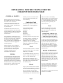
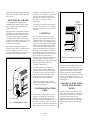
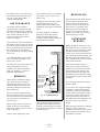
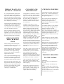
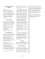
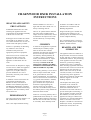
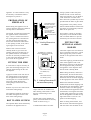
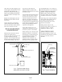
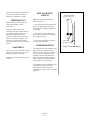
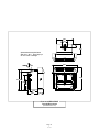
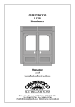
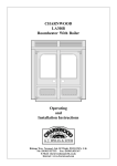
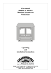
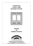
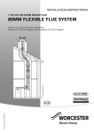
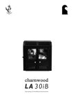
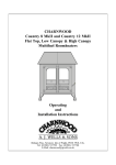
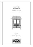
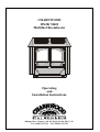
CHARNWOOD
DX20i MkII
Multifuel Roomheater
Operating
and
Installation Instructions
Bishops Way, Newport, Isle Of Wight, PO3O 5WS, U.K.
Tel: (01983) 537799 Fax: (01983) 537788
OPERATING INSTRUCTIONS FOR THE
CHARNWOOD DX20i MKII
GENERAL POINTS
Before lighting the fire check with
the installer that the work and checks
described in the installation
instructions have been carried out
correctly and that the chimney has
been swept, is sound, and free from
any obstructions.
WARNING There must not be an
extractor fan fitted in the same room
as this appliance as this can cause the
appliance to emit smoke and fumes
into the room.
If the appliance is fitted in place of
an open fire then the chimney should
be swept one month after installation
to clear any soot falls which may
have occurred due to the difference in
combustion between the appliance
and the open fire.
When using the fire in situations
where children or infirm people are
present please use a fire guard to
prevent accidents. The fire guard
should be manufactured in
accordance with BS 6539.
FUELS
The following fuels may be burnt on
this fire. Please pay careful attention
to the special points made with each
type of fuel as they will help you to
get the best from your fire. It must be
remembered that only smokeless fuels
may be burnt in smoke control areas
on this fire. If you are not sure
whether you are in a smoke control
area, then please check with your
Local Authority.
Smokeless Fuels
The following smokeless fuels are
suitable for use on this appliance:
Ancit (Phurnacite Plus),
Anthracite Large Nuts,
Centurion,
Extracite,
Maxibrite,
Phurnacite,
Sunbrite Doubles,
Welsh Dry Steam Coal (Large Nuts).
The above fuels are all suitable for
use in smoke control areas. New
smokeless fuels are regularly
produced, and your fuel supplier will
be able to recommend those which
will be suitable.
Coal
Housecoal doubles, trebles or cobbles
may all be burnt. Do not use singles,
small nuts, or coal dust
It is important that large size coal is
used (i.e. larger than 50mm or 2" in
size). The coal should be dry.
When burning bituminous coal a
little extra care is needed. Please take
note of the section "Special Points
For Burning Coal".
Wood
Only dry well seasoned wood should
be burnt on this appliance as burning
wet unseasoned wood will give rise to
heavy tar deposits. For the same
reason hard wood is better than soft
wood. Burning wet unseasoned wood
Page 2
HV 7/96
will also result in considerably
reduced outputs. The wood should be
cut and split and then left to season
in a well ventilated dry place for at
least one year but preferably two
years before use.
Peat
Ensure that the peat is well dried
before use. Burning wet peat will
give rise to heavy tar deposits and
reduced outputs.
PETROLEUM COKE IS NOT
SUITABLE FOR USE ON THIS
APPLIANCE, ITS USE WILL
INVALIDATE THE GUARANTEE
At first you may find it helpful to try
several fuels to find the most suitable.
If you are unable to obtain the fuel
you want ask your supplier or an
approved fuel distributor to suggest
an alternative, or ring the Solid Fuel
Association Helpline on Freephone
0800 600 000.
DOOR OPERATION
Use the spanner type tool to open and
close the doors. Turn the knob on the
right hand door anti-clockwise to
open and clockwise to close. When
closing the doors do not push on the
enamel with the tool as this can chip
the enamel, instead push the doors on
the door knobs.
There is a safety device fitted to the
fire which prevents the main doors
being closed when the ashpit door is
open. This is to prevent accidental
over-firing.
The sequence for opening and closing
the doors is as follows:
Open the main doors Open the ashpit
door Close the ashpit door Close the
main doors
MULTIFUEL GRATE
Your Charnwood is fitted with a
multifuel grate which enables solid
fuel, wood and peat to be burned
equally effectively.
The grate has two positions. One for
solid fuel, the other for wood and
peat. When in the solid fuel position
ash can fall through the grate and
into the ashpan. When in the wood
position ash is able to build up on the
grate as is necessary for effective
wood or peat burning.
Movement of the grate from one
position to the other is effected using
the tool supplied. The grate is put
into the wood position by moving the
tool direction of the arrow "W"
(marked on the handle of the tool)
until the tool is vertical. The grate is
put into the solid fuel position by
moving the tool in the direction of
the arrow "C" until the tool is
horizontal.
If a mixture of wood and solid fuel,
or peat and solid fuel, is to be burnt
then keep the grate in the solid fuel
position.
LIGHTING
Set the grate into either the wood
position or the solid fuel position as
required. Place some paper and dry
kindling wood or fire lighters on the
grate and cover with a small amount
of fuel. Turn the thermostat control
knob to the maximum setting, fully
open the airwash control and light
the paper or fire lighters. Leave the
doors slightly ajar until the fuel is
well ignited then load with more fuel,
close the doors and adjust the
thermostat and airwash control to the
desired setting. Leaving the main
doors slightly ajar when lighting will
keep the glass clean while the
airwash is warming up.
On initial lighting, the fire may
smoke and give off an odour as the
silicon paint with which the firebox
is painted reacts to the heat. This is
normal and will cease after a short
time. In the meantime the room
should be kept well ventilated.
Before relighting the fire, riddle,
remove any clinker from the firebed
and empty the ashpan.
Control
Knob
Air Inlet Damper
Fig. 1. Thermostat Control
Airwash
Control
Closed
Open
CONTROLLING THE
FIRE
The rate of burning and hence the
output is controlled by the control
knob on the left hand side of the
appliance and the airwash control on
the right, (see Figs. 1 & 2.) Use the
control knob on the left to control the
heat output from the fire and keep the
Page 3
HV 7/96
Fig. 2. Airwash Air Control
airwash control slightly open most of
the time to keep the glass clean. It
will not be possible to keep the glass
clean if the airwash control is fully
closed, particularly after refuelling.
The number at the top of the control
knob is the number at which it is set,
the higher the number the faster the
burning rate.
RUNNING THE FIRE
WITH THE DOORS
OPEN
The fire may be run with the doors
open. This will result in a reduction
in efficiency and hence heat output.
The more reactive fuels, like
homefire, wood and coal will burn
better when the doors are open than
fuels like phurnacite, sunbrite and
ancit.
For safety reasons, if the fire is to be
left unattended with the doors open
then use a spark guard which
complies with BS 3248.
ASH CLEARANCE
The ashpan must be emptied
regularly before it becomes too full.
The most convenient time to remove
the ash is just before riddling the fire
since the ash will then be at it’s
coolest. Use the tool provided to
remove the ashpan.
using solid fuel do not go beyond the
45° position as this can cause the
grate to jam.
If jamming does occur then the fire
should be allowed to burn for
approximately half an hour before
riddling the grate again as described
above.
Too much riddling can result in
emptying unburnt fuel into the
ashpan and should therefore be
avoided. Clinker should regularly be
removed from the firebed.
Never allow the ash to accumulate in
the ashpan so that it comes in contact
with the underside of the grate as this
will seriously damage the grate bars.
Ensure that the air inlet damper is
not prevented from closing by spilled
fuel or ash.
To make ash removal easier there is a
special Charnwood ash carrier
available. This may be purchased
from your supplier or, in case of
difficulty, from ourselves.
When burning solid fuels riddling
twice a day is usually sufficient.
When burning wood or peat, ash
should be allowed to build up and
generally riddling every other day
will be sufficient.
The fire should be riddled with all
doors shut. Place the tool on the knob
and rotate between the horizontal and
the 45° position several times as
shown in Fig. 3.
When burning wood or peat do not
riddle all the ash into the ashpan,
keep a layer about 12 mm (1/2 inch)
thick on the grate.
Keep the firebox well filled (the fuel
may be sloped up from the front
firebars), but do not allow fuel to
spill over the top of the front fire
bars. Take care, especially when
burning wood, that fuel does not
project over the front fire bars or
damage to the glass may be caused
when the doors are closed.
OVERNIGHT
BURNING
Empty the ashpan, if necessary, and
then riddle the fire. If the fire is very
low then it may be necessary to add a
little fuel and turn the thermostat
control up for a brief period until the
fire is burning well before filling with
fuel. When burning wood use large
logs overnight as they will burn more
slowly than small ones.
Care should be taken to ensure that
ash is cool before emptying it into
plastic liners or bins.
RIDDLING
REFUELLING
Do Not Go Beyond
45º Position
When Riddling
Tool To Be
Vertical For
Wood
RiddleBetween
Horizontal &
45º Positions
Some experimentation may be
necessary to find the setting most
suitable for the particular fuel used
and the draw on the chimney, but
generally the thermostat should be
turned down to the minimum setting
and the airwash control nearly closed
overnight.
For overnight burning the fire doors
must be closed.
Tool To Be
Horizontal For
Solid Fuel
Fig. 3. Grate Operation
After riddling, the grate should be
put back into the solid fuel or wood
position as required (the tool should
be horizontal for solid fuel or vertical
for wood or peat).
Caution: when riddling the grate
Page 4
HV 7/96
To revive the fire, empty the ashpan
if necessary, riddle (when burning
solid fuel), and turn the thermostat
control knob to maximum and open
the airwash control. When the fire is
burning well load on more fuel as
necessary and set the thermostat and
airwash controls to the desired
setting.
When burning wood do not riddle but
simply set the air controls to
maximum until the fire picks up and
then set them at the desired setting
and refuel as necessary.
THROAT PLATE AND
FLUEWAY CLEANING
CLEANING AND
MAINTENANCE
It is important that the throat plate
and all the appliance flueways are
kept clean. When burning smokeless
fuels they should be cleaned monthly.
When burning other fuels they should
be cleaned at least once a week, and
more frequently if necessary.
The appliance is finished in vitreous
enamel. To clean the surfaces simply
wipe over with a dry cloth. Abrasive
pads and scouring cleaners must not
be used as these will damage the
finish. Care should be taken not to
knock the enamel with hard objects
as it will chip.
The throat plate and flueways may be
cleaned with a low fire still burning.
Use the scraper tool to scrape any
sooty deposits to the front of the plate
until they fall off into the fire.
More soot will be deposited on the
throat plate and in the flueways if the
appliance is run at low levels for long
periods. If this is the case then more
frequent cleaning will be necessary.
SPECIAL POINTS
WHEN BURNING
COAL
When burning housecoal keep the
airwash control at least slightly open
all the time (refer to Fig 2.).
When loading the appliance take care
not to smother the fire, instead fill
the firebox in two stages waiting
between each stage for the flames to
appear above the fire.
After a period of slumbering always
turn the air control up to maximum
and wait until flames appear above
the fuel bed before opening the doors.
Burning coal will produce more soot
deposits than other fuels, especially if
the fire is run at low levels for long
periods. It is therefore vital to clean
the throat plate regularly, daily
cleaning is recommended.
The glass in the doors is a zero
expansion ceramic glass which will
not crack due to the heat of the fire.
Before cleaning the glass open the
doors and allow them to cool. Clean
the glass using a damp cloth and then
wiping over with a dry cloth. Any
stubborn deposits may be removed
with a proprietary stove glass cleaner
or ceramic hob cleaner. Some
deposits on the glass may be burnt off
simply by running the fire at a fast
rate for a few minutes. Do not use
abrasive cleaners or pads as these can
scratch the surface which will weaken
the glass and cause premature failure.
Aerosol spray cleaners should not be
used near the appliance whilst it is
under fire.
If the fire is going to be out of use for
a long period (for instance in the
summer) then to prevent condensation, and hence corrosion, the
thermostat should be left at the
maximum setting and the main doors
left ajar. It is also advisable to sweep
the chimney and clean out the fire.
After long periods where the fire has
been out of use, the chimney and
appliance flueways should be cleaned
before lighting.
For the fire to operate correctly it is
important that the door seals are in
good condition. Check that they do
not become worn or frayed and
replace them when necessary.
Page 5
HV 7/96
CHIMNEY SWEEPING
The chimney should be swept at least
twice a year. In most installations it
will be possible to sweep the chimney
through the appliance.
First remove the front firebars and
the throat plate. Then sweep the
chimney ensuring that soot is
removed from all horizontal surfaces
after sweeping.
In situations where it is not possible
to sweep through the appliance the
installer will have provided
alternative means, such as a soot
door. After sweeping the chimney the
appliance flue outlet and the flue pipe
connecting the appliance to the
chimney must be cleaned with a flue
brush.
After clearing any soot from within
the fire, replace the throat plate and
the front firebars.
Different types of sweep's brushes are
available to suit different flueways.
For standard brick chimneys a wire
centre sweep's brush fitted with a
guide wheel is recommended. For
prefabricated insulated chimneys the
manufacturers instructions with
regard to sweeping should be
consulted.
TROUBLE SHOOTING
Fire Will Not Burn.
Check that:
a) the air inlet is not obstructed in
any way,
b) that chimneys and flueways are
clear,
c) that a suitable fuel is being used,
d) that there is an adequate air supply
into the room,
e) that an extractor fan is not fitted in
the same room as the fire.
Fire Blazing Out Of
Control.
Check that:
a) the doors are tightly closed,
b) the thermostat knob is turned
down to the minimum setting,
c) the air inlet damper is closed (at
the bottom left of the appliance), and
that it is not prevented from closing
completely by a piece of ash,
d) a suitable fuel is being used,
e) the door seals are in good
condition.
Over-Firing
If the fire is over-fired it will cause
premature failure of the internal fire
parts. Overfiring is occurring when
any internal parts of the fire begin to
glow red. To prevent over-firing
ensure that:
a) the door seals are kept in good
condition, and that the doors are
sealing correctly,
b) the thermostat on the fire is
working correctly,
c) a suitable fuel is being used.
Fume Emission.
Warning Note: Properly installed and
operated this appliance will not emit
fumes. Occasional fume from
de-ashing and re-fuelling may occur.
Persistent fume emission is
potentially dangerous and must not
be tolerated. If fume emission does
persist then the following immediate
actions should be taken:
A) Open doors and windows to
ventilate the room.
B) Let the fire out and safely dispose
of fuel from the appliance.
C) Check for flue or chimney
blockage, and clean if required.
D) Do not attempt to relight fire until
cause of fume has been identified, if
necessary seek professional advice.
The most common cause of fume
emission is flueway or chimney
blockage. For your own safety these
must be kept clean.
Door Glass Blacks Up
Keeping the glass clean requires a
certain amount of experimentation
due to the differences in the draw of
different chimneys. The following
points should be noted and with a
little care should enable the glass to
be kept clean in most situations:
a) The airwash relies on a supply of
heated air to keep the glass clean,
therefore, when lighting the stove
allow the firebed to become well
established before turning the
thermostat down. This may also be
necessary when re-fuelling the stove.
b) When re-fuelling keep the fuel as
far back from the front firebars as
possible, do not try to fit too much
fuel into the firebox.
c) Never completely close the airwash
control - as a guide it should be at
least a quarter open.
d) Wet wood or logs overhanging the
front firebars will cause the glass to
blacken.
It is always more difficult to keep the
glass clean when running the stove
very slowly for long periods. It is
important that the chimney draw is
sufficient, (when the chimney is
warm a draught reading of at least
0.10 inches water gauge should be
obtained), and that it is not affected
by down-draught.
Freezing
If a boiler is fitted do not light the
fire if there is any possibility that any
parts of the system may be frozen.
Chimney Fires.
If the chimney is thoroughly and
regularly swept, chimney fires should
not occur. However, if a chimney fire
does occur turn the control knob to
the minimum setting, and tightly
close the doors of the appliance. This
Page 6
HV 7/96
should cause the chimney fire to go
out in which case the control should
be kept at the minimum setting until
the fire in the appliance has gone out.
The chimney and flueways should
then be cleaned. If the chimney fire
does not go out when the above
action is taken then the fire brigade
should be called immediately.
After a chimney fire the chimney
should be carefully examined for any
damage. Expert advice should be
sought if necessary.
CHARNWOOD DX20i INSTALLATION
INSTRUCTIONS
HEALTH AND SAFETY
PRECAUTIONS
WARNING Please take care when
installing the appliance that the
requirements of the Health and Safety
at Work Act 1974 are met.
Some types of fire cement are caustic
and should not be allowed to come
into contact with the skin. In case of
contact wash with plenty of water.
If there is a possibility of disturbing
any asbestos in the course of
installation then please use
appropriate protective equipment.
There must not be an extractor fan
fitted in the same room as the
appliance as this can cause the
appliance to emit fumes into the
room.
There must be an adequate air supply
into the room in which the appliance
is installed totalling at least 100
square cm. (16 square inches) to
provide combustion air. This is
particularly necessary if the room is
double glazed.
In addition to these instructions the
requirements of BS:8303 and
BS:6461 Pt 1&2; 1984 must be
fulfilled. Local Authority Bye-laws
and Building Regulations regarding
the installation of Solid Fuel burning
appliances, flues and chimneys must
also be observed.
PERFORMANCE
The rated output for the DX20i is 5.4
kW (18800 btu/h) to the room.
Sunbrite Doubles at a rate of 1.0
kg/hr with the doors closed over a 4
hourly re-fuelling interval.
be fitted in accordance with the
manufacturers instructions and
Building Regulations.
There is an optional add-in domestic
hot water boiler available with an
output of 2.0 kW (6800 btu/h). If this
is fitted then the output to the room
will be reduced by a corresponding
amount.
Single wall flue pipe is suitable for
connecting the appliance to the
chimney but is not suitable for using
for the complete chimney.
CHIMNEY
In order for the appliance to perform
satisfactorily the chimney height
must not be less than 4 metres
measured vertically from the outlet of
the fire to the top of the chimney.
The chimney should preferably be
175 mm (7 inches) or 200mm (8
inches) internal diameter or square
with sides of 175mm or 200mm
internally and MUST NOT BE
LESS THAN 150mm (6 INCHES)
INTERNAL DIAMETER OR 150 x
150mm INTERNAL SQUARE.
If an existing chimney is to be used it
must be swept and checked, it must
be in good condition, free from
cracks and blockages, and should not
have an excessive cross sectional area
(e.g. greater than 250mm x 250mm).
If you find that the chimney is in
poor condition then expert advice
should be sought regarding the
necessity of having the chimney
lined. If it is found necessary to line
the chimney then a lining suitable for
Solid Fuel must be used.
If there is no existing chimney then a
prefabricated block chimney or a twin
walled insulated stainless steel flue to
BS:4543 can be used either internally
or externally. These chimneys must
This is the output obtained burning
Page 7
HV 7/96
If it is found that there is excessive
draw in the chimney then a draught
stabiliser should be fitted.
HEARTH AND FIRE
SURROUND
The appliance must be installed on a
fireproof hearth and must be situated
at least 300 mm (12 inches) from any
combustible material. The positioning
of the appliance and the size of the
hearth are governed by building
regulations for Class 1 appliances.
These building regulations state that
the hearth must extend in front of the
appliance by at least 300 mm (12
inches) and to the sides by at least
150 mm (6 inches). If in doubt as to
the positioning of the appliance
expert advice should be sought either
from the supplier or the local
building inspector.
The fireplace must allow good
circulation of air around the
appliance, especially above it, to
ensure that maximum heat is
transferred to the room and also to
prevent the fireplace overheating. A
gap of 150mm (6 inches) each side
and 300mm (12 inches) above the
appliance should give sufficient air
circulation. If a wooden mantelpiece,
beam or surround is used in the
fireplace it should be a minimum of
460mm (18 inches), and preferably
600mm (24 inches) above the
appliance. In some situations it may
be necessary to shield the beam or
mantelpiece to protect it.
storage cylinder to BS:1566 part 1
should be used in most situations,
unless the appliance is to be fitted in
a soft water area in which case a
direct hot water cylinder may be used
provided that the boiler is glass lined.
PREPARATION OF
FIREPLACE
This Dimension Is The
Minimum Level Area
Required To Enable The
Ashpit Door To Be
Opened.
For Overall Sizes Of
Hearth See The
Section Titled "Hearth".
Before fitting the appliance into an
existing fireplace remove the fireback
and any loose in-fill material.
The hearth, surround and opening for
the appliance must conform with
Figs. 5 and 6. The flat area around
the opening must be a minimum of
750 mm wide and 660 mm high.
Ensure that the hearth and the base
in the opening are flat, level, and at
right angles to the surround.
Make a hole in the front of the
chimney breast to give access for
infilling and fixing the flue pipe. If
the optional boiler is to be fitted it
will also be necessary to make a hole
in the side of the chimney breast to
give access for the pipework.
265 mm Minimum
400 mm
Minimum
Fig. 4. Limiting Dimensions
Of Hearth
The shaded area on the face of
the surround is the minimum flat
area required.
Apply fire cement to the rear face of
the sealing flange on the appliance.
Fit the appliance into the opening
ensuring that it is central and that a
good seal is made between the
sealing flange and the face of the
surround.
Remove any excess fire cement from
around the sealing flange.
The appliance should be screwed to
the hearth through the holes at the
base of the sealing flange.
HOT WATER SYSTEM
The optional add-in boiler which may
be fitted in the appliance has an
If an indirect cylinder is used then
the primary circuit should be filled
with a suitable inhibitor to prevent
the build up of scale and corrosion.
FITTING THE
OPTIONAL ADD-IN
BOILER
The boiler replaces the rear firebrick
and is reversible so that the 1" B.S.P.
male tappings may come on either
the left or the right hand side of the
boiler.
750 mm
FITTING THE FIRE
In some cases it may be necessary to
place the connecting flue pipe in the
chimney before fitting the fire into
the fireplace.
All pipework in the primary circuit
must be 28mm diameter and the flow
pipe must rise continuously from the
boiler to the open vent.
660 mm
Dim. A:
Max. 470mm (18 1/2")
Min. 405mm (16")
Dim. B:
Max. 575mm (22 2/3")
Min. 555mm (21 3/4")
Fig. 5. Limiting Dimensions Of
Surround And Opening
output sufficient for domestic hot
water heating. If the boiler is fitted
then the room heating will be
reduced.
The hot water system should be a
gravity circuit and must be correctly
vented as shown in Fig. 6.
A double feed indirect hot water
Page 8
HV 7/96
The boiler tappings protrude from the
sides of the appliance and it will
therefore be necessary to fit the boiler
into the appliance after positioning
the appliance in the fireplace if the
fire surround is already fitted.
Before fitting the boiler, remove the
front firebars, the side and back fire
plates and the firebricks. Knock out
the knock-outs for the boiler tappings
on the appropriate side of the firebox.
Remove the backnuts and fibre
washers from the boiler tappings and
fit the boiler into the appliance. Place
the fibre washers over the tappings
on the outside of the appliance and fit
the backnuts, ensuring that the boiler
is held tightly against the rear inside
face of the appliance and that the top
edge of the boiler is level or runs
uphill to the flow tapping.
When re-fitting the firebricks, note
that the short side firebrick supplied
with the boiler must be fitted on the
same side as the boiler tappings. One
of the original side firebricks is fitted
on the other side, and the rear
firebrick is discarded. The firebricks
must be fire cemented into position,
wetting the firebox will improve the
adhesion.
Replace the back fireplate, the side
fireplates, the front firebar and the
throat plate.
Connect the boiler to the heating
system ensuring that the flow pipe
rises from the boiler. Fill the system
with water and check for leaks.
FLUE CONNECTION
AND INFILLING
Make the flue connection with the
special 150° elbow part no.
010/AV12. Please note that this item
is ordered separately from the
appliance. a short length of flue pipe.
The legs of the elbow may be cut on
site to suit the chimney. Also note
that the legs of the elbow are
different lengths to enable some
situations to be catered for by turning
the elbow around.
The end of the flue pipe must line up
with the centre-line of the chimney,
and must also extend to the point
where the chimney narrows to its
final size. Any large voids must be
filled and flaunched to the flue pipe
to ensure that all soot deposits can be
cleared when the appliance is swept,
and to prevent problems with the
operation of the appliance.
Ensure that the flue pipe is not
obstructed or restricted in any way
and that all joints are well sealed.
Before infilling cover the front of the
appliance to protect it. Ensure that
the flue pipe is central and then fill
the space between the body of the
appliance and the structural
brickwork with vermiculite (e.g.
micafil or similar) concrete. Ensure
that there are no air pockets. The
22mm Open Vents
Feed and Expansion Tank
Overflow
recommended mix is six volumes of
vermiculite granules to one volume of
portland cement thoroughly mixed
together. Enough water should be
added so that no more than one or
two drops of water are released when
a handful of the mixture is squeezed.
After filling with vermiculite flaunch
the top of the flue connector pipe to
the chimney with lime mortar.
Ensure that the flue pipe is well
sealed to the chimney.
Make good the hole(s) in the
chimney breast making sure that it is
completely airtight. A typical
installation is shown in Fig. 7.
In most installations it will be
possible to sweep the chimney
through the appliance. If this is not
possible then some alternative means
(such as a soot door), must be
provided.
Cold Water Tank
Flaunching
Overflow
Take FluePipe
Up To Narrowest
Part Of Chimney.
Domestic Hot Water Draw Off
Gravity Return 28mm
Gravity Flow 28mm
150º Elbow
Part No. 010/AV12
Drain Cock
Indirect Hot Water Cylinder
150º
Vermiculite
Infill
Drain Cock at Lowest Point
Fig. 6. Typical Hot Water System
Using Indirect Hot Water Cylinder
Fig. 7. Typical Installation
Page 9
HV 7/96
The free inset method of installation
may be used instead of infilling.
Details are available on request.
THERMOSTAT
Before lighting the fire check the
cold setting distance of the
thermostat.
With the control knob at the
minimum setting the flap should be
just closed as shown in Fig. 8. To
adjust the distance slacken the
locking nut and adjust as necessary.
When set correctly re-tighten the
locking nut. Ensure that the flap
opens and closes freely as the knob is
turned.
ASSEMBLY
Fit the side panels and hood onto the
appliance. Instructions for this are
enclosed with the panel pack.
Replace any internal parts previously
removed.
PRE LIGHTING
CHECK
Flap Just Closed With
Knob Set To Minimum
Before initial lighting check the
following points:
1. The bottom grate bars must all be
fitted and should move freely and
easily when the riddling mechanism
is operated.
2. The plates round the sides and
back of the grate must be in position
and sitting correctly.
3. The throat plate must be fitted in
the roof of the appliance.
COMMISSIONING
On completion of the installation and
after allowing a suitable period of
time for the fire cement and mortar to
dry out, the fire should be lit and
checked to ensure that smoke and
fumes are taken from the appliance
up the chimney and emitted safely.
Also check all joints and seals.
On completion of the installation and
commissioning please leave the
operating instructions with the
customer and advise on the use of the
appliance.
Page 10
HV 7/96
Locking Nut
Thermostat Flap
Fig. 8. Thermostat Setting
400
150
i/d
84
260
Optional Boiler May BeFitted
With The1" B.S.P. MaleTappings
On TheLeft Or TheRight.
620
150º
604
547 506
405
265
200
260
120
Charnwood DX20i M kI I
Overall Dimensions
(Dimensions are in mm)
Page 11
HV 7/96