1
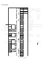
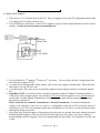
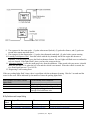
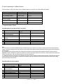
INSTALLATION GUIDE
By Firstech, Inc.
Website: www.compustar.org
TABLE OF CONTENTS
Wiring Diagram
A. Notes for Wire Connection… … … … … … … … … … … … … … ..… … 3
B. Dip Switch and Jumper Setting… … … … … … … … … ...… … ...… … 4
C. Installation of Antennas and RPS (Remote Paging System)… ....5
D. Option Program for Four Button Remotes… … … … … … … … … ...5
E. Option Program for Six Button Remotes… … … … … … … … … … ..6
F. Programming Options… … … … … … … … … … … … … … … … … … ..6
G. Diagnostic Problems with Auto-Start… … … … … … … … … … … … .7
H. Limited Lifetime Consumer Warranty… … … … … … … … … … … … 7
© Firstech, Inc. Page 1
Wiring Diagram
CN1
CN2
OFF/
ON
DI
P1
CN12
3
Cold Se nsor
4Whi
te
5Vi
ole t
6Ye llow
5:
Anti
-Gri
nd
6:
Starte r
7Gr/
Rd
8Black
7:I
gni
ti
on
8:
(
-)
1
Gr/
Wh
(
-)
L
i
ght
250m A
2
Bk
(
-)
Status
250m A
3
Gr
(
-)
I
gni
ti
on
250m A
4
Wh/
Bk
(
-)
Acce ssory
250m A
5
Rd /
Bk
(
-)
Starte r
250m A
1
Lt.Blue
(
-)
E-Brak e Se nsi
ng
2
Gray/
Bk
(
-)
Hood Se nsi
ng
3
Lt.
Blu/
Wh
(
+)Brak e Se nsi
ng
4
Vi
ole t/
Bk
Re d
(
-)
Trunk Se nsi
ng
(
-)
Door Se nsi
ng:I
nstallati
on re qui
re d for Manual
Transm i
ssi
on
(
+
)
Door Se nsi
ng:I
nstallati
on re qui
re d for Manual
Transm i
ssi
on
7
Brow n /
Bk
(
-)
Glow Plug
8
Brow n /
Wh
(
+)
Glow Plug
9
Ye llow /
Bk
Engi
ne Se nsi
ng
10
none
1
2
3
4
none
Vi
ole t/
Wh
Or/
Bk
Blue
(
+
)
(
-)
Trunk Unlock
nd
(
-)
2 Pulse Unlock
(
-)
Unlock
250m A
250m A
250m A
5
Blue /
Bk
(
-)
L
ock
250m A
6
none
(
-)
1
Orange
(
-)
Re arm
250m A
2
Or/
Wh
(
-)
Di
sarm
250m A
6
DI
P
Tach Le arni
ng Sw i
tch Sw
4
3
2
1
3Rd /
Wh
1:
(
+)12VConstant
2:
Pk i
ng Lt.
3:
(
+) 12VConstant,Pre w i
re d
nd
Re lay for 2 I
g,Accor Starte r 4:
Acce ssory
CN3
15(
2
5
)
/
2
5
(
4
5
) DI
P2
Ante nna
2G/
Wh
5
Manual/
Auto (
cut) Jum p e r
Alt/
Tach
1Re d
(
-)
(
+)
Tx
Rx
CN11
CN5
(
-)
2
Te m p
1
(
+)
1
(
-)
CN4
CN10
Rd /
Wh
© Firstech, Inc. Page 2
A. Notes for Wire Connection
1. There are two 12 V Constant Wires in the CN1. One is to supply power to the CPU and ignition and the other
is to supply power to Starter and Accessory.
2. Pre-wired Relay for Anti-Grind - Violet at CN1 supplies a negative 250mA output when the system is remote
starting. The Yellow wire from 87a should go to the Starter Motor side.
3. Pre-wired Relay for 2nd Ignition, 2nd Starter or 2nd Accessory. You may select the relay’s trigger input from
one of the three outputs of CN2.
4. (-) Output for the Parking lights: Some vehicles, such as Jeep, have negative Parking lights. Please note that
this output is for only 250 mA. only.
5. (-) Status Output: This comes in one second before ignition on and continues until one second after ignition
off.
6. Light Blue of CN3: You need to tie this wire into the emergency brake for Manual Transmission Mode or
Turbo mode. Most emergency brake wires will show 12V at rest when the ignition is on or ground when you
set the brake. In either Manual Transmission or Turbo Mode, the engine will stay running for two minutes
after the key is turned off.
Wire Connection for Automatic Transmission vs. Manual Transmission. For manual transmission
vehicles, three additional connections are required – 1) Red/White or Red wire of CN3 to the door switch, 2)
Light Blue wire of CN3 to the emergency brake and 3) Red/Black wire of CN2 to over-ride the clutch switch
momentarily during remotestart.
7. Glow Plug wires for diesel engines: If the negative glow plug wire sees ground, the remote starting is delayed
until this ground disappears. Likewise, if the positive glow plug wire sees positive, the remote starting is
delayed until this positive disappear. There is no programming for diesel mode. It is automatic once this wire
is used.
© Firstech, Inc. Page 3
8. The sequence for the rearm pulse: (1) pulse when armed (locked), (2) pulse after Starter, and (3) pulse one
second after remote start shut down.
9. The sequence for the disarm pulse: (1) pulse when disarmed (unlocked), (2) pulse before remote starting.
10. Learning Tach/Injector Wire: Start the vehicle with the key manually and let the engine idle down to a
minimum. The next step is to press the black tachometer button. The car's lights will flash once to confirm the
tach was learned. If the lights flash 3 times, you have the wrong tach wire.
11. Alternator Sensing: Locate the small gauge wire from the alternator. When tested with your meter, it should
show you less than 3V/dc when the key is on and the vehicle is not started. When the vehicle is started, the
wire should read between 7V to 14V/dc.
12. Diagnosing Tach Learning Error
If the cars parking lights flash 3 times, there is a problem with the tachometer learning. Wait for 2 seconds and the
cause for the error will be indicated by the number of times the parking lights flash.
Error Number (# of times parking
lights flash)
1
2
3
Tach Learning Error Diagnosis
Dip Switch #1 is on alternator sensing.
Manual Car Key is in the off position.
No signal or the signal is not fast
enough. Find a different wire.
B. Dip Switches and Jumper Setting
Dip
Switch
On
Off
Jumper Wire
#1
#2
Uncut: Manual Transmission
Cut: Automatic Transmission
Tach Sensing
Altermator Sensing
25 min run time (45 min diesel)
15 min run time (25 min diesel)
© Firstech, Inc. Page 4
Important! Once you cut the Jumper Wire, you are not allowed to reconnect the wire. The reconnection will completely void
the warranty. A trace of reconnection of this wire will prevent you from any claim whatsoever pertaining to the manual
transmission mode.
C. Installation of Antennas and RPS.
The antennas have been calibrated for horizontal installation at the top-left corner of the windshield. Different installation
may adversely affect the transmitting distance.
D. Option Programming for Four Button Remotes
Step 1: For programming menu 1: Press Buttons (I+II) for 2 seconds.
For programming menu 2: Press Buttons (I+IV) for 2 seconds. The parking lights will flash once indicating that you are in
programming mode.
Step 2: Within 2 seconds after pressing (I+II) or (I+IV), press Button IV the number of times to go to the option number you want
to change. You will see the parking light flash each time when you press Button IV.
Step 3: Wait a few seconds. You will see a number of parking light flashes corresponding to the option number you want to
change. If the number of flashes, do not correspond with what you want, Revert to Step 1.
Step 4: Press Button I for the default factory settings and your car will respond with one flash of the parking lights. Press Button II
for the optional setting and your car will respond with two parking light flashes.
?? If you see an extended flash of the lights, you are going out of programming mode, please go back to Step 1.
?? If you want to change more options, go back to Step 1.
Resetting the Programming Options to the factory default settings.
Step 1: Press Buttons (I+II) simultaneously or Buttons (I+IV) simultaneously for 2 seconds. A one flash of the parking lights confirms step 1.
Step 2: Press Button III three times. This is confirmed by a parking light flash each time you press Button III. A few second later, your cars parking lights
will flash three times rapidly. Your car is now set to all of the original factory default settings.
© Firstech, Inc. Page 5
E. Option Programming for Six Button Remotes
The procedures will be the same as the 4 button remotes except the use of the different buttons.
Programming
Programming Menu 1
Programming Menu 2
Option Selection
Factory Setting
Option Selection
Default Setting Selection
6 Button Remote
(Trunk+Start)(Trunk+Stop)(Stop)Lock
Unlock
(Start)-
4 Button Remote
(I+II)(I+IV)(IV)
(I )
(II )
(III)
F. Programming Menu Options
Programming Menu #1 (Auto-Start and Door Lock Options)
Feature
1-1
1-2
1-3
1-4
1-5
1-6
1-7
Unlock Before, Lock After Starting,
Lock after remote start
Door Lock / Unlock Pulse Duration
Min. Crank Time for the Alternator
Sensing
Driver’s Priority Unlock
Double Pulse Unlock
N/A
Turbo
Factory Default Setting –
Button I
OFF
Optional Setting – Button II
0.8 sec
0.8 sec
2.5 sec
1.0 sec
OFF
OFF
ON
ON
OFF
ON
ON
Note
1-1 Some vehicles such as Mercedes-Benz and the Lexus ES300 require you to unlock the car to disarm the factory alarm before remote starting the
vehicle. Activating this feature will unlock the vehicle for a brief second in order to disarm the factory alarm before auto-starting the vehicle remotely then
lock after starting.
1-4 This feature unlocks the driver’s side door lock with the first unlock pulse. A second unlock pulse is needed to unlock the rest of the car doors.
Important! In order for this feature to operate, the installer must use the 2nd Unlock Wire (Or/Bk wire of Connector 4). Isolate the driver’s door motor from
the rest of the other doors. Call us for technical support if you are not sure about this.
1-7 Turbo mode requires the connection of the emergency brake wire for either automatic or manual transmission vehicles. With this mode, engine will
continue running for two minutes after key is turned off if the emergency brake was set before the key was turned off and the foot brake was not being
pressed when the key was turned off.
Programming Menu #2 (Security Options)
Feature
2-1
2-2
2-3
2-4
2-5
2-6
2-7
2-8
Cold Start with Temp Sensor
Timer Start or Minimum Interval
between Cold Starts
N/A
N/A
Ignition Controlled Door Lock
N/A
N/A
N/A
Factory Default Setting –
Button I
OFF
3 Hr
Optional Setting – Button II
OFF
ON
ON
1.5 Hr
© Firstech, Inc. Page 6
Note:
2-1 Cold start mode requires installation of the optional temperature sensor. In the default factory setting, Cold Sensor input works as Remote Start
Activation Input. A Ground pulse to this wire will start the vehicle
2-5 Automatic Transmission Vehicle: This programmable option enables your vehicle to automatically lock the doors upon starting
the vehicle with a key. In addition, the vehicle will automatically unlock the doors upon pulling the key out from the ignition. This
option must be chosen at the time of installation.
Manual Transmission Vehicle or Turbo Mode: This programmable option will lock the doors in 5 seconds after starting the vehicle
with a key and the emergency brake is released.
G. Diagnosing problems with Auto -Start
If there is a problem in auto-starting your car, you will see three flashes of the parking lights when you attempt to auto-start the car. Wait for 2 seconds and
the cause for the error, will be indicated by the number of times the parking lights flash.
Error Number (# of times
parking lights flash)
1
2
3
4
5
6
7
Error Reason
Engine On
Key On
Door Open
Trunk Open
Brake On
Hood Open
Reservation Off (Manual Transmission
Only)
H. Limited Lifetime Consumer Warranty
Firstech, Inc Warrants to the original purchaser that this product shall be free of defects in material and workmanship under normal use and circumstances
for the period of time that the original owner of this product owns the vehicle in which it is installed; except that the remote controller unit for the period of one
year from the date of installation to the original owner of this product. When the original purchaser returns the product to the retail store where it was
purchased or pre-paid postal to Firstech, Inc., 801 E. 82nd Ave Suite 1 Anchorage, Alaska 99518, USA within the warranty period, and if the product is
defective, Firstech, Inc, will at its option repair or replace such.
TO THE MAXIMUM EXTENT ALLOWED BY LAW, ANY AND ALL WARRANTIES ARE EXCLUDED BY THE MANUFACTURER AND EACH ENTITY
PARTICIPATING IN THE STREAM OF COMMERCE THEREWITH. THIS EXCLUSION INCLUDES BUT IS NOT LIMITE D TO, THE EXCLUSION OF ANY
AND ALL WARRANTY OF MERCHANTABILITY AND/OR ANY AND ALL WARRANTY OF FITNESS FOR A PARTICULAR PURPOSE AND/OR ANY AND
ALL WARRANTY OF NON -INFRINGEMENT OR PATENTS, IN THE UNITED STATES OF AMERICA AND/OR ABROAD. NEITHER THE
MANUFACTURER OF ANY ENTITIES CONNECTED THEREWITH SHALL BE RESPONSIBLE OR LIABLE FOR ANY DAMAGES WHATSOEVER,
INCLUDING BUT NOT LIMITED TO, ANY CONSEQUENTIAL DAMAGES, INCIDENTAL DAMAGES, DAMAGES FOR LOSS OF TIME, LOSS OF
EARNINGS, COMMERCIAL LOSS, LOSS OF ECONOMIC OP PORTUNITY AND THE LIKE. NOTWITHSTANDING THE ABOVE, MANUFACTURER
DOES OFFER A LIMITED WARRANTY TO REPLACE OR REPAIR THE CONTROL MODULE AS DESCRIBED ABOVE. Some states do not allow
limitations on how long an implied warranty will last or the exclusion or limitation on how long an implied warranty will last or the exclusion or limitation of
incidental or consequential damages. This warranty gives you specific legal rights, and you may also have other rights, which vary State to State.
Firstech, Inc. is not RESPONSIBLE OR LIABLE FOR ANY DAMAGES WHATSOEVER, INCLUDING BUT NOT LIMITED TO, ANY
CONSEQUENTIAL DAMAGES, INCIDENTAL DAMAGES, DAMAGES FOR LOSS OF TIME, LOSS OF EARNINGS,
COMMERCIAL LOSS, LOSS OF ECONOMIC OPPORTUNITY AND THE LIKE that may or may not resul ted from the operation of
CompuStar. NOT WITHSTANDING THE ABOVE, MANUFACTURER DOES OFFER A LIMITED WARRANTY TO REPLACE OR
REPAIR THE CONTROL MODULE AS DESCRIBED ABOVE.
© Firstech, Inc. Page 7