1
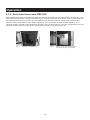
User’s Operating Instructions
Bioflo
Pellet Central Heating System Boiler
These instructions should be read in conjunction with the
Supplementary Instructions
Please keep these instructions in a safe place.
If you move house, please hand them over to the next occupier.
© Baxi Heating UK Ltd 2010
Baxi Bioflo 12 kW Granite
Baxi Bioflo 12 kW Pearl
InfoWIN operating unit
© Baxi Heating UK Ltd 2010 All rights reserved. No part of this publication may
be reproduced or transmitted in any form or by any means, or stored in any
retrieval system of any nature (including in any database), in each case whether
electronic, mechanical, recording or otherwise, without the prior written
permission of the copyright owner, except for permitted fair dealing under
Copyrights, Designs and Patents Act 1988.
Applications for the copyright owner’s permission to reproduce or make other
use of any part of this publication should be made, giving details of the proposed
use, to the following address:
The Company Secretary, Baxi Heating UK Ltd,
Brooks House, Coventry Road, Warwick. CV34 4LL
Full acknowledgement of author and source must be given.
WARNING: Any person who does any unauthorised act in relation to a
copyright work may be liable to criminal prosecution and civil claims for damages.
Table of contents:
Page
Important information for system operators . . . . . . . . . . . . . . . . . . . . . . . . . . . . . . .5
1.1
Safety precautions . . . . . . . . . . . . . . . . . . . . . . . . . . . . . . . . . . . . . . . . . . . . . . . . . . . . . . . . . . . . . . . . . .5
1.2
Fuel . . . . . . . . . . . . . . . . . . . . . . . . . . . . . . . . . . . . . . . . . . . . . . . . . . . . . . . . . . . . . . . . . . . . . . . . . . . . . . .5
1.3
Start-up and maintenance . . . . . . . . . . . . . . . . . . . . . . . . . . . . . . . . . . . . . . . . . . . . . . . . . . . . . . . . . . . .6
1.4
Checking the heating water . . . . . . . . . . . . . . . . . . . . . . . . . . . . . . . . . . . . . . . . . . . . . . . . . . . . . . . . . . .6
1.5
Operating noises . . . . . . . . . . . . . . . . . . . . . . . . . . . . . . . . . . . . . . . . . . . . . . . . . . . . . . . . . . . . . . . . . . . .6
1.6
Filling the pellet store . . . . . . . . . . . . . . . . . . . . . . . . . . . . . . . . . . . . . . . . . . . . . . . . . . . . . . . . . . . . . . . .7
1.7
Sources of danger . . . . . . . . . . . . . . . . . . . . . . . . . . . . . . . . . . . . . . . . . . . . . . . . . . . . . . . . . . . . . . . . . . .8
1.7.1
1.7.2
1.7.3
Fire protection . . . . . . . . . . . . . . . . . . . . . . . . . . . . . . . . . . . . . . . . . . . . . . . . . . . . . . . . . . . . . . . .8
Power failure (or if the blower is not running) . . . . . . . . . . . . . . . . . . . . . . . . . . . . . . . . . . . . .8
Burner pot . . . . . . . . . . . . . . . . . . . . . . . . . . . . . . . . . . . . . . . . . . . . . . . . . . . . . . . . . . . . . . . . . . .8
Operation . . . . . . . . . . . . . . . . . . . . . . . . . . . . . . . . . . . . . . . . . . . . . . . . . . . . . . . . . . . .9
2.1
Functional description, function elements and operating controls . . . . . . . . . . . . . . . . . . . . . . . . . . .9
2.2
2.1.1 BAXI Bioflo . . . . . . . . . . . . . . . . . . . . . . . . . . . . . . . . . . . . . . . . . . . . . . . . . . . . . . . . . . . . . . . . . .9
2.1.2 Heat shield . . . . . . . . . . . . . . . . . . . . . . . . . . . . . . . . . . . . . . . . . . . . . . . . . . . . . . . . . . . . . . . . . .10
Check before initial start-up . . . . . . . . . . . . . . . . . . . . . . . . . . . . . . . . . . . . . . . . . . . . . . . . . . . . . . . . . .11
2.3
Filling the reserve supply container . . . . . . . . . . . . . . . . . . . . . . . . . . . . . . . . . . . . . . . . . . . . . . . . . . .11
2.4
2.3.1 BAXI Bioflo – Manual filling . . . . . . . . . . . . . . . . . . . . . . . . . . . . . . . . . . . . . . . . . . . . . . . . . . . .11
Info panel . . . . . . . . . . . . . . . . . . . . . . . . . . . . . . . . . . . . . . . . . . . . . . . . . . . . . . . . . . . . . . . . . . . . . . . . .12
2.5
Operating modes . . . . . . . . . . . . . . . . . . . . . . . . . . . . . . . . . . . . . . . . . . . . . . . . . . . . . . . . . . . . . . . . . .13
2.6
2.5.1 OFF mode . . . . . . . . . . . . . . . . . . . . . . . . . . . . . . . . . . . . . . . . . . . . . . . . . . . . . . . . . . . . . . . . . .13
2.5.2 ON mode, lighting ON, self-test, lighting OFF . . . . . . . . . . . . . . . . . . . . . . . . . . . . . . . . . . . . .13
2.5.3 Pellet feed . . . . . . . . . . . . . . . . . . . . . . . . . . . . . . . . . . . . . . . . . . . . . . . . . . . . . . . . . . . . . . . . . .14
2.5.5 Manual operation . . . . . . . . . . . . . . . . . . . . . . . . . . . . . . . . . . . . . . . . . . . . . . . . . . . . . . . . . . . .15
2.5.6 Flue cleaning function . . . . . . . . . . . . . . . . . . . . . . . . . . . . . . . . . . . . . . . . . . . . . . . . . . . . . . . .16
2.5.7 Shutdown procedure . . . . . . . . . . . . . . . . . . . . . . . . . . . . . . . . . . . . . . . . . . . . . . . . . . . . . . . . .16
Operating phases . . . . . . . . . . . . . . . . . . . . . . . . . . . . . . . . . . . . . . . . . . . . . . . . . . . . . . . . . . . . . . . . . .17
2.7
2.6.1 Standby . . . . . . . . . . . . . . . . . . . . . . . . . . . . . . . . . . . . . . . . . . . . . . . . . . . . . . . . . . . . . . . . . . . .17
2.6.2 Purging . . . . . . . . . . . . . . . . . . . . . . . . . . . . . . . . . . . . . . . . . . . . . . . . . . . . . . . . . . . . . . . . . . . . .17
2.6.3 Ignition phase . . . . . . . . . . . . . . . . . . . . . . . . . . . . . . . . . . . . . . . . . . . . . . . . . . . . . . . . . . . . . . .17
2.6.4 Flame stabilisation . . . . . . . . . . . . . . . . . . . . . . . . . . . . . . . . . . . . . . . . . . . . . . . . . . . . . . . . . . .17
2.6.5 Modulation mode . . . . . . . . . . . . . . . . . . . . . . . . . . . . . . . . . . . . . . . . . . . . . . . . . . . . . . . . . . . .17
2.6.6 Burnout . . . . . . . . . . . . . . . . . . . . . . . . . . . . . . . . . . . . . . . . . . . . . . . . . . . . . . . . . . . . . . . . . . . .17
2.6.7 Burner OFF . . . . . . . . . . . . . . . . . . . . . . . . . . . . . . . . . . . . . . . . . . . . . . . . . . . . . . . . . . . . . . . . .17
Information text . . . . . . . . . . . . . . . . . . . . . . . . . . . . . . . . . . . . . . . . . . . . . . . . . . . . . . . . . . . . . . . . . . . .18
2.8
2.7.1
2.7.2
2.7.3
2.7.4
2.7.5
2.7.6
2.7.7
2.7.8
2.7.9
Menu
2.9
2.8.1 Operator level . . . . . . . . . . . . . . . . . . . . . . . . . . . . . . . . . . . . . . . . . . . . . . . . . . . . . . . . . . . . . . .22
2.8.2 Service level . . . . . . . . . . . . . . . . . . . . . . . . . . . . . . . . . . . . . . . . . . . . . . . . . . . . . . . . . . . . . . . .28
Heating system operation . . . . . . . . . . . . . . . . . . . . . . . . . . . . . . . . . . . . . . . . . . . . . . . . . . . . . . . . . . .29
Next boiler cleaning . . . . . . . . . . . . . . . . . . . . . . . . . . . . . . . . . . . . . . . . . . . . . . . . . . . . . . . . . .18
Operating hours . . . . . . . . . . . . . . . . . . . . . . . . . . . . . . . . . . . . . . . . . . . . . . . . . . . . . . . . . . . . .18
Pellet consumption total . . . . . . . . . . . . . . . . . . . . . . . . . . . . . . . . . . . . . . . . . . . . . . . . . . . . . . .19
Flue gas temperature . . . . . . . . . . . . . . . . . . . . . . . . . . . . . . . . . . . . . . . . . . . . . . . . . . . . . . . . .19
Boiler temperature setpoint . . . . . . . . . . . . . . . . . . . . . . . . . . . . . . . . . . . . . . . . . . . . . . . . . . . .19
Current boiler output . . . . . . . . . . . . . . . . . . . . . . . . . . . . . . . . . . . . . . . . . . . . . . . . . . . . . . . . .19
Display module software version . . . . . . . . . . . . . . . . . . . . . . . . . . . . . . . . . . . . . . . . . . . . . . .19
Firing automate software version . . . . . . . . . . . . . . . . . . . . . . . . . . . . . . . . . . . . . . . . . . . . . . .19
Boiler model . . . . . . . . . . . . . . . . . . . . . . . . . . . . . . . . . . . . . . . . . . . . . . . . . . . . . . . . . . . . . . . .19
guide . . . . . . . . . . . . . . . . . . . . . . . . . . . . . . . . . . . . . . . . . . . . . . . . . . . . . . . . . . . . . . . . . . . . . . .20
3
Table of contents:
Page
Care, cleaning and maintenance . . . . . . . . . . . . . . . . . . . . . . . . . . . . . . . . . . . . . . . .43
3.1
Care of the front window, cladding and keyboard foil . . . . . . . . . . . . . . . . . . . . . . . . . . . . . . . . . . . .31
3.2
Cleaning and operating implements . . . . . . . . . . . . . . . . . . . . . . . . . . . . . . . . . . . . . . . . . . . . . . . . . . .31
3.3
Overview of intervals between maintenance . . . . . . . . . . . . . . . . . . . . . . . . . . . . . . . . . . . . . . . . . . . .31
3.4
Heating surfaces . . . . . . . . . . . . . . . . . . . . . . . . . . . . . . . . . . . . . . . . . . . . . . . . . . . . . . . . . . . . . . . . . . .33
3.5
Ash pan, ash on heating surface . . . . . . . . . . . . . . . . . . . . . . . . . . . . . . . . . . . . . . . . . . . . . . . . . . . . . .33
3.6
Combustion chamber . . . . . . . . . . . . . . . . . . . . . . . . . . . . . . . . . . . . . . . . . . . . . . . . . . . . . . . . . . . . . . .34
3.7
3.6.1 Baffle plate, thermocontrol sensor . . . . . . . . . . . . . . . . . . . . . . . . . . . . . . . . . . . . . . . . . . . . . .34
3.6.2 Burner pot . . . . . . . . . . . . . . . . . . . . . . . . . . . . . . . . . . . . . . . . . . . . . . . . . . . . . . . . . . . . . . . . . .35
BAXI Bioflo reserve supply container . . . . . . . . . . . . . . . . . . . . . . . . . . . . . . . . . . . . . . . . . . . . . . . . . .36
3.8
Top heating surfaces and linkage . . . . . . . . . . . . . . . . . . . . . . . . . . . . . . . . . . . . . . . . . . . . . . . . . . . . .37
3.9
Pressure measuring nipple, rotary feeder, blower wheel, blower box and exhaust pipe . . . . . . . .38
3.9.1
3.9.2
3.9.3
Pressure measuring nipple for combustion chamber pressure switch . . . . . . . . . . . . . . . . .38
Rotary feeder . . . . . . . . . . . . . . . . . . . . . . . . . . . . . . . . . . . . . . . . . . . . . . . . . . . . . . . . . . . . . . . .38
Blower wheel, blower box and exhaust pipe to flue . . . . . . . . . . . . . . . . . . . . . . . . . . . . . . . .39
Troubleshooting . . . . . . . . . . . . . . . . . . . . . . . . . . . . . . . . . . . . . . . . . . . . . . . . . . . . . .40
4.1
No display on Info panel . . . . . . . . . . . . . . . . . . . . . . . . . . . . . . . . . . . . . . . . . . . . . . . . . . . . . . . . . . . .41
4.2
Information messages . . . . . . . . . . . . . . . . . . . . . . . . . . . . . . . . . . . . . . . . . . . . . . . . . . . . . . . . . . . . . .41
4.3
Fault messages . . . . . . . . . . . . . . . . . . . . . . . . . . . . . . . . . . . . . . . . . . . . . . . . . . . . . . . . . . . . . . . . . . . .42
4.4
Alarm messages . . . . . . . . . . . . . . . . . . . . . . . . . . . . . . . . . . . . . . . . . . . . . . . . . . . . . . . . . . . . . . . . . . .43
Declaration of conformity . . . . . . . . . . . . . . . . . . . . . . . . . . . . . . . . . . . . . . . . . . . . . .47
4
Important information for system operator
1.1
Safety precautions
The boiler and related accessories are state of the art and meet all applicable safety regulations.
Your boiler and all accessories operate using 230 V AC electric current. Improper installation or repair can pose
the danger of life-threatening electric shock. Installation may be performed only by appropriately qualified technicians.
Caution symbols
Please take careful note of the following symbols in this Operating Manual.
Ignoring the warnings identified can lead to personal injury.
Ignoring the warnings identified can lead to malfunction of or damage to the boiler or heating system.
1.2
Fuel
The boilers are designed to burn the following fuels:
Pellets according to ÖNORM M7135 and DINplus.
Significant criteria based on the standards are as follows:
Diameter 6 mm
Smooth surface
Residual moisture content max. 10%
Length 80% between 15 – 30 mm
Density at least 1.1 kg/dm3
Energy content min. 18 MJ/kg = 5 kWh/kg
(in water-free condition)
Abraded particles max. 2.3%
Ash content max. 0.5%
Chemical/synthetic binding agents are strictly prohibiNo impurities from varnish or paint residues, etc.
ted
The pellets must be stored in a dry place so that they can be transported without problems and in order to
achieve trouble-free operation with optimum combustion and at maximum efficiency.
5
Important information for system operators
1.3
Start-up and maintenance
Have Baxi Customer Service or one of our customer service PARTNERS put your new boiler into service. In this
way, all functions of the new unit will be thoroughly checked; you will also benefit from the detailed information provided by the system installer. Installation by a qualified technician as well as the maintenance required
by the guarantee limitations will guarantee the optimal use and service life of your boiler system. This is the
only way to assure the benefits of this technologically advanced boiler and guarantee safe, environmentally
friendly and energy-saving system operation.
The following preconditions must be met before you commencing the initial start-up:
1.) Boiler installed correctly.
2.) System fully wired up electrically.
3.) System rinsed, filled and vented – heat consumption must be possible.
4.) Hot water tank connected to domestic water and filled.
5.) Sufficient quantity of fuel available (pellets, split logs, oil or gas).
6.) The customer must be present during start-up.
The initial start-up cannot be carried out if any of these points are neglected. The customer will be charged for
any unnecessary costs arising as a result. Start-up and maintenance are part of the guarantee requirements as
listed in the enclosed „guarantee limitations“.
Note: During the first few weeks after start-up, condensation can occur in the combustion chamber, on the heating surfaces and in the ash pan. This has no effect on the function and service life of the boiler.
1.4
Checking the heating water
The chemical composition of the heating water must meet the specifications of ÖNORM H 5195 Part 1 or VDI
2035 T1. According to ÖNORM M 5195 Part 1, the condition of the heating water must be checked every 2 years
by a heating technician in order to avoid corrosion and sediment accumulation in the heating system.
The check must be performed once every year in heating systems with more than 1500 litres of heating water.
In the event of repair work requiring a change of water in the heating system, the heating water is to be checked
within 4 to 6 weeks after such work. Corrosion and sediment resulting from improper heating water are not
covered by the guarantee and warranty.
1.5
Operating noises
The BAXI Bioflo is a modern, fully automated pellet central heating boiler for living areas with a high level of convenience in terms of operation and cleaning. This automation means that operating noises may occur during normal operation.
Normal operating noises are:
Flame noises – Natural flame noise can be heard depending on the size of the combustion rate.
Light scratching and scraping noises – Depending on the level of contamination, cleaning noises may occur
during automated cleaning or shake-out. If these become louder over time ⇒ Clean the pellet central heating
boiler for living areas, especially the burner pot.
Trickling of pellets and vacuum cleaner noise – Fully automated pellet supply involves pellets being sucked from
the storage room into the reserve supply container. During filling, the suction turbine generates a „vacuum cleaner noise“ in the storage room and the feed hose, and the trickling of the pellets can be heard in the reserve
supply container.
Clicking noises – The relays switch on or off when the control unit is installed.
Liquid noise, gurgling – This is caused by air in the heating water ⇒ Bleed the system.
Air induction noises – Air induction noise occurs at the air supply induction point for combustion (air opening
in the device) ⇒ Use air supply pipes to relocate the induction point outside the house or into an adjacent room.
Note: Due to these operating and flame noises, we do not recommend installing the device in bedrooms or
quiet rooms – see also the information in the BAXI Bioflo Assembly instruction , „Installation“.
6
Important information for system operators
1.6
Filling the pellet store
The pellet flue-connected stove must be switched off correctly at least 15 minutes before the store is
filled – Fig. 2. Press the ON/OFF button. Never switch off using the emergency OFF switch!
Pressing one of the six buttons firstly switches just the
lighting and display on. The boiler is only switched off
when the button is pressed for the 2nd time. Wait until
burnout mode has finished (not indicated on the display)
and open the combustion chamber doors.
During filling, negative pressure is created in the pellet
store and this can cause burn-back in the pellet boiler. Therefore, the boiler must be stopped from operating during
the filling procedure.
7
Fig. 2
Switching off FireWIN
Important information for system operators
1.7
Sources of danger
1.7.1
Fire protection
The entire system must comply with technical fire protection requirements in accordance with the applicable
regulations, standards and guidelines.
All flammable materials in the close vicinity of the pellet central heating boiler for living areas must be protected against the effects of heat, in particular in the area of the front window.
Do not drape clothing or other items over the BAXI Bioflo for drying them.
Do not touch the front window – danger of burns.
1.7.2
Power failure (or if the blower is not running)
Do not open the combustion chamber door, there is an increased risk of deflagration when opening the
combustion chamber door. A self-test is performed following a power failure during combustion and
then operation is continued automatically.
1.7.3
Burner pot
Never fill the burner pot with pellets by hand. Excessive combustion material in the burner pot means
that the pellets will not be ignited optimally. Too much low temperature carburisation gas will be generated and this can lead to deflagration.
8
Operation
2.1
Functional description, function elements and operating controls
The BAXI Bioflo automatically fires when the control system signals a heating requirement. Following „purging“ (safety function), ignition starts and the pellet metering auger switches on. The burner pot is automatically filled with pellets. When flame formation has been detected (by the thermocontrol sensor), the boiler enters
flame stabilisation mode and then control mode (modulation mode) and keeps to the specified boiler temperature setpoint (between 60 °C and 75 °C). The boiler enters burnout mode if the output drops below the minimum nominal thermal output or no heating requirement is signalled by the control system. The blower continues to run until the burner pot has cooled down. Therefore, do not switch off the electricity supply to the device
too soon.
2.1.1 BAXI Bioflo
The reserve supply container is loaded by hand. The heating surfaces are cleaned manually using the cleaning
lever. The cleaning residues from the heating surfaces and the combustion residues from the burner pot drop
into the ash pan or ash pan space.
1 . . . .Ash pan
2 . . . .Ash door
3 . . . .Filling and evacuation cock
4 . . . .Primary air pin
5 . . . .Pressure gauge
6 . . . .Burner pot
7 . . . .Heat shield
8 . . . .Down chute
9 . . . .Pressure measuring nipple
10 . . .Combustion chamber door
11 . . .Lug for hanging in
the heat shield
12 . . .Baffle plate
13 . . .Thermocontrol sensor
14 . . .Cladding door
15 . . .Heating surface cover
16 . . .Safety valve
17 . . .Info panel operating unit
18 . . .Reserve supply container cover
19 . . .Glass cover
20 . . .Pellet reserve supply container
22 . . .Boiler temperature
safety thermostat B7
23 . . .Rotary feeder
safety thermostat B7a
24 . . .Auger and motor
25 . . .Rotary feeder
26 . . .Rotary feeder cleaning opening
27 . . .Exhaust pipe
28 . . .Exhaust pipe cleaning opening
29 . . .Blower motor
30 . . .Blower box
Fig. 3
9
BAXI Bioflo – view from right
Operation
2.1.4 Heat shield (accessory FIRE 023)
Heat radiated from the front window can lead to unwanted heating of the room where the unit has been set up
when domestic hot water is being heated during the summer. If you do not want the room to be heated, you
can significantly reduce the amount of heat radiated using the patented heat shield (accessory Fire 023).
The air-to-water ratio without a heat shield is approx. 15 : 85 % and with a raised heat shield approx. 9 : 91 %.
The heat shield is located in the combustion chamber. This can be pulled up using the supplied Allen key and
hooked into the lugs on the sides of the combustion chamber cover plates, Figs. 4, 5.
Fig. 4
Hooking in the Allen key
Fig. 5
10
Pulling up the heat shield and hooking it into the lugs on the sides
Operation
2.2
Check before initial start-up
a) System pressure (heating water pressure):
The system must be filled and vented. With the system cold, pressure should be at least 1.0 bar (maximum
1.8 bar) – Fig. 6 If you have any questions, your installer will gladly answer them.
Pressure gauge (system pressure)
Filling and evacuation cock
Fig. 6
Filling the system
b) Ventilation:
If you are operating the device with room air, please make sure the room where it is installed is well ventilated. The air supply must be as free of dust as possible.
c) Flue:
Please have the chimney sweep check the flue, and, if necessary, clean it.
2.3
Filling the reserve supply container
2.3.1 BAXI Bioflo – Manual filling
Note: Do not open the reserve supply container cover unless the glass cover is closed, in order to avoid damaging the glass cover.
Fold open the cover of the reserve supply container (Fig. 7) and fill the reserve supply container up to max. 1
cm below the edge. Close the cover.
Tip:The reserve supply container should always be completely filled with pellets. This allows the incoming pellets to drop into the container better, reduces the size of the conical part of the pile and means that the container empties better.
When filling, make sure no extraneous materials (e.g. shreds of the pellet bags resulting from cutting
open the bags) enter the reserve supply container – they could block the rotary feeder!
Fig. 7
Folding open the cover
11
Operation
2.4
Info panel
The Info panel is located at the top under the glass cover. Press the locking button at the front and fold the glass
cover open, the Info panel pops up automatically – Figs. 8, 9. It consists of a large full text display, an ON/OFF
button with an LED signal lamp indicating Operation (green) or Malfunction (red), a button for manual operation / flue cleaning function as well as four individual menu buttons. The function of each menu button is displayed on the Menu line.
Fig. 8
Fig. 9
Press the locking button
Info panel pops up
Signal lamp (LED)
„Operation“ – green;
„Malfunction“ – red
Full-text display
(illuminated display)
Manual operation / flue cleaning
function
Boiler temperature
38
°C
ON/OFF button
Standby
Info
5s
Menu
Operating
phases
are
displayed here, including
Standby, Burner OFF, etc.
Assignment of buttons to
their specific function
RESET
Menu line
Fig. 10
Info panel
Menu buttons
The various operating modes are displayed on Info panel together with the corresponding operating phases.
Corresponding operating phases:
The following operating modes exist:
–
–
–
–
–
–
–
OFF
ON (with self-test, lighting ON, lighting OFF)
Pellet feed
Solid fuel / buffer mode
Manual operation
Flue cleaning function
Shutdown procedure
12
–
–
–
–
–
–
–
–
Standby
Purging
Ignition phase
Flame stabilisation
Modulation mode
Burnout
Burner OFF
Switch off heat generator
Operation
2.5
Operating modes
2.5.1 OFF mode
The boiler is switched off when in OFF mode. The display and all
buttons, with the exception of the ON/OFF button, do not function.
The LED on the Info panel is not illuminated – Fig. 11.
5s
RESET
Fig. 11
OFF mode
2.5.2 ON mode, lighting ON,
self-test, lighting OFF
Self-test active
Press the ON/OFF button, lighting and display are switched on and
the self-test starts automatically – Fig. 12.
5s
.....
(Animated symbol)
Self-test:
Sensors, switches and motors are checked during the self-test.
After a successful self-test, the display shows an operating phase
and the boiler water temperature (standard display). The LED signal lamp lights green and the desired functions can be selected
using the buttons – Fig. 13.
If the self-test was unsuccessful, an information message (e.g. information, fault, alarm) is displayed (see sections 4.3 and 4.4).
RESET
Fig. 12
Self-test
Boiler temperature
42
°C
5s
(Operating phases)
Info
Menu
RESET
Fig. 13
Standard display
Lighting ON/OFF
Boiler temperature
The display lighting switches off automatically after 10 min. (Fig.
14). Pressing one of the six buttons switches the lighting on again
for 10 min.
42
°C
(Operating phases)
Lighting ON
RESET
Info panel identifies and stores the various operating modes and
states. Once the system is switched on, other operating modes may
also be displayed instead of the standard display, such as manual
operation or solid fuel/buffer mode; malfunctions are also displayed. These operating modes and states are described later in these
instructions.
13
Fig. 14
Display lighting OFF
5s
Operation
2.5.3 Pellet feed
Pellet feed – Burnout
Pellet feed
Pellet feed from the storage room into the reserve supply container has been
requested. Combustion is stopped. Pellet transport into the burner pot is stopped, the vacuum fan continues to run until all the remaining pellets have been
burned and the burner pot has cooled down. – Fig. 15
42
°C
Fig. 15
Burnout
Info
Menu
Pellet feed in operation
Pellet feed
in operation
The pellet feed is in operation. Pellets are supplied from the storage room into
the reserve supply container. The burner is locked – Fig. 16.
42
°C
Fig. 16
14
Burner locked
Info
Menu
Operation
2.5.5 Manual operation
Pressing one of the six buttons switches the lighting and display on.
Manual operation starts if the Manual operation / flue cleaning function button is pressed for more than five seconds – Fig. 17. This sets
the boiler temperature to the setpoint fixed for manual operation
(standard value 60 °C). The control system is not affected by this. The
lighting is switched off after the lighting timer has counted down (10
min.); the function or display remains unchanged.
Manual operation
Boiler temperature
42
°C
(Symbol flashes)
(Operating phases)
–
Cancel
The various operating phases are displayed here, including Burner in operation, Burner OFF, etc.
5s
+
Press for
5 seconds
RESET
Fig. 17
Pressing the Cancel button or the Manual operation / flue cleaning
function button terminates the function – Fig. 18. The boiler returns
to automatic operation.
Manual operation
Boiler temperature
42
°C
(Symbol flashes)
(Operating phases)
–
Cancel
5s
+
RESET
Fig. 18
Setpoint adjustment for manual operation
Manual operation
set temperature
By pressing the + or – button the display switches to the set temperature adjustment mode – Fig. 19. Use the + or – button to change the setpoint in 1 K steps. The temperature set in this mode is
not permanently saved. The original set temperature is used once
manual operation ends.
–
70
°C
Back
+
5s
RESET
Fig. 19
By pressing the Back button (Fig. 20) or after waiting 45 seconds,
the screen returns to its previous display.
Manual operation
set temperature
(Symbol flashes)
–
70
Back
RESET
Fig. 20
15
°C
+
5s
Operation
2.5.6 Flue cleaning function
This function aids the performance of legally-required emissions testing.
Briefly pressing the Manual operation / flue cleaning function button
switches on the display illumination. Pressing the button again starts
the flue cleaning function – Fig. 21. The boiler temperature is set to
approx. 60 °C for 45 min.
Flue cleaning function
Power 100%
45min
42
°C
(Symbol flashes)
5s
(Operating phases)
30%
Cancel 100%
The various operating phases are
displayed here, including Burner in
operation, Burner OFF, etc.
RESET
Fig. 21
Pressing the corresponding menu button enables the boiler to be operated with 30 % or 100 % output – Fig. 22. The lighting is switched off
after the lighting timer has counted down (10 min); the function or
display remains unchanged. When the button is first pressed only the
lighting is switched on.
When the Manual operation / flue cleaning function button is pressed again the operating time is reset to 45 min.
Flue cleaning function
Power 30%
45min
42
°C
(Symbol flashes)
5s
(Operating phases)
30%
Cancel 100%
RESET
Fig. 22
Flue cleaning function
Power 30%
45min
The flue cleaning function ends
42
°C
– when the Cancel button is pressed – Fig. 23.
(Symbol flashes)
– automatically after about 45 minutes.
5s
(Operating phases)
30%
Cancel 100%
RESET
Fig. 23
2.5.7 Shutdown procedure
The green LED flashes
Shutdown procedure
The boiler is switched off – Fig. 24.
42
°C
Burnout
Info
Menu
RESET
Fig. 24
16
5s
Operation
2.6
Operating phases
2.6.1 Standby
Boiler temperature
During this operating phase, the control system does not transmit requests
for heat. The burner is switched off and the boiler temperature setpoint is 0 °C
– Fig. 25.
42
°C
Fig. 25
Standby
Info
Menu
After an hour in standby mode, the display is shut down fully and only the
green LED is lit up. The display is switched back on by pressing a button or
when there is a heating requirement.
2.6.2 Purging
Boiler temperature
The vacuum fan runs, the combustion chamber of the BAXI Bioflo is flushed
through with fresh air. This phase can last several minutes before the burner
fires – Fig. 26.
42
°C
Fig. 26
2.6.3 Ignition phase
Purging
Info
Menu
Boiler temperature
The vacuum fan runs, pellets are transported into the burner pot and are ignited. When flame formation is detected, the system switches over to flame stabilisation – Fig. 27.
42
°C
Fig. 27
2.6.4 Flame stabilisation
Ignition phase
Info
Menu
Boiler temperature
42
°C
Following the ignition procedure, uniform combustion is established and then
the system switches over to modulation mode – Fig. 28.
Fig. 28
2.6.5 Modulation mode
Flame stabilisation
Info
Menu
Boiler temperature
42
°C
The burner is in modulation mode. The output can be infinitely varied between
30 % and 100 % – Fig. 29.
Note: In the modulation mode briefly no flame can be visible during the automatic burner ash removal!
Fig. 29
2.6.6 Burnout
Modulation mode
Info
Menu
Boiler temperature
Combustion is stopped. Pellet transport into the burner pot is stopped, the
vacuum fan continues to run until all the remaining pellets have been burned
and the burner pot has cooled down – Fig. 30.
42
°C
Fig. 30
2.6.7 Burner OFF
Burnout
Info
Menu
Boiler temperature
There is a heating requirement from the control system, but the boiler temperature (actual value) is higher than the boiler temperature setpoint. This
means combustion is stopped and the burner is switched off – Fig. 31.
17
42
°C
Fig. 31
Burner OFF
Info
Menu
Operation
2.7
Information text
Boiler temperature
42
°C
Pressing the Info button calls up the most important BAXI Bioflo
information – Fig. 32.
5s
(Operating phases)
Info
Menu
The arrow buttons select and display sub-menus – Fig. 33. By pressing the Back button (Fig. 34) or waiting 45 seconds, the screen
returns to the standard display.
RESET
Fig. 32
The following information texts exist:
–
–
–
–
–
–
–
–
–
Next boiler cleaning in about[h]
Operating hours [h]
Pellet consumption total [t]
Flue gas temperature [°C]
Boiler temperature setpoint [°C]
Current boiler output [%]
Display module software version
Firing automate software version
Boiler model
Next boiler
cleaning in about
300
h
5s
Back
RESET
Fig. 33
Next boiler
cleaning in about
300
h
5s
Back
RESET
Fig. 34
2.7.1 Next boiler cleaning
Next boiler
cleaning in about
Display showing the operating time in hours remaining until the next boiler
cleaning – Fig. 35.
Note:The operating time remaining until the next boiler cleaning depends on
the operating method and is constantly recalculated. Therefore, there may be
deviations from the normal operating hours.
300
Fig. 35
2.7.2 Operating hours
h
Back
Operating hours
1.234
The total number of burner operating hours is displayed – Fig. 36
Fig. 36
18
Back
h
Operation
2.7.3 Pellet consumption total
Pellet consumption
total
The total amount of pellets consumed is displayed in tonnes – Fig. 37.
Note:The „Pellet consumption total“ is a calculated value and can differ from
the actual value by ±15%.
1.30
Fig. 37
t
Back
2.7.4 Flue gas temperature
Flue gas temperature
If a flue gas temperature sensor (accessory) is connected, this function displays
the current flue gas temperature – Fig. 38.
The flue gas temperature is measured directly on the flue outlet. It may
therefore deviate from a standard measurement.
114
°C
Fig. 38
2.7.5 Boiler temperature setpoint
Back
Boiler temperature
setpoint
63
°C
The display indicates the boiler temperature setpoint as calculated by the control system. This setpoint is used to control the burner – Fig. 39.
Fig. 39
2.7.6 Current boiler output
Back
Current
boiler output
70
%
The current boiler output is displayed in %. The boiler output (modulation
mode) can be set from 30 % to 100 % – Fig. 40.
Fig. 40
2.7.7 Display module software version
Back
Software version display module
4.00
The current software version of the display module (Info panel) is displayed
– Fig. 41.
Fig. 41
2.7.8 Firing automate software version
Back
Software version
firing automate
4.10
The current software version of the firing automate (main PCB) is displayed –
Fig. 42.
Fig. 42
2.7.9 Boiler model
Back
Boiler model
Pellet boiler 120K
Boiler
0
The boiler model of the BAXI Bioflo is displayed – Fig. 43.
Fig. 43
19
Back
Operation
2.8
Menu guide
Boiler temperature
42
°C
Pressing the Menu button changes the menu display to operator
level or service level – Fig. 44.
5s
(Operating phases)
Info
Menu
Use the arrow buttons to select the operator level or service level
(Fig. 45) and confirm with the Choose button – Fig. 46.
The menu item or sub-menu item is exited by pressing the Back
button (Fig. 47) or after a delay of 45 seconds.
RESET
Fig. 44
Only trained service personnel may perform system modifications in the service level.
Operator level
Service level
5s
Choose
Back
RESET
5ig. 49
Operator level
Service level
5s
Choose
Back
RESET
Fig. 46
Operator level
Service level
5s
Choose
Back
RESET
Fig. 47
20
Operation
Menu structure:
Menu
Service level
Operator level
Boiler
cleaning
Time
With enable
time
(reserved for trained service
personnel only)
Feed
operating mode1)
With start time
Automatic
1)
Time profile
feed1)
Probe
switching1)
With enable time:
Start/finish
With start time:
Start
Without
time control
Switched off
Only probe 1
Only probe 2
Time profile
ash comp.
Start time 1
08:00
Start time 2
22:00
Only probe 3
Only displayed if a feed system is present and if this has been adjusted by a trained service technician in the service level.
21
Operation
2.8.1 Operator level
Boiler temperature
Pressing the Menu button changes to the „Operator level“ and
„Service level“ – Fig. 48.
42
°C
(Operating phases)
Info
5s
Menu
RESET
Fig. 48
Use the arrow buttons to select „Operator level“ and confirm with
the Choose button – Fig. 49.
Operator level
Service level
5s
Choose
Back
RESET
Fig. 49
In the operator level, use the arrow buttons to select the required
sub-menu (Fig. 50) and confirm with the Choose button.
Adjusting the:
Boiler cleaning: 2.8.1.1
Time: see section 2.8.1.2.
Feed operating mode: see section 2.8.1.3.
Time profile feed: see section 2.8.1.4.
Probe switching: see section 2.8.1.5.
Time profile ash compression : see section 2.8.1.6
Boiler cleaning
Time
Feed operating mode
Time profile feed
Probe switching
Time profile ash comp.
Choose Back
5s
RESET
Fig. 50
The menu item or sub-menu item is exited by pressing the Back
button (Fig. 51) or after a delay of 45 seconds.
Boiler cleaning
Time
Feed operating mode
Time profile feed
Probe switching
Time profile ash comp.
Choose Back
RESET
Fig. 51
22
5s
Operation
2.8.1.1
Boiler cleaning Resetting the cleaning request
Boiler temperature
42
°C
After boiler cleaning has been performed (section 3.1), boiler cleaning must be confirmed so that the operating time until the next
boiler cleaning is restarted.
5s
(Operating phases)
Lighting ON
Boiler cleaning must not be reset if cleaning has not been
carried out.
RESET
Pressing one of the six buttons switches the lighting and display
on – Fig. 52.
Fig. 52
Press the Menu button – Fig. 53.
Boiler temperature
42
°C
5s
(Operating phases)
Info
Menu
RESET
Fig. 53
Confirm the selected menu item „Operator level“ by pressing the
Choose button – Fig. 54.
Operator level
Service level
5s
Choose
Back
RESET
Fig. 54
Use the arrow buttons to select the „Boiler cleaning“ sub-menu
item – Fig. 55.
Boiler cleaning
Time
Feed operating mode
Time profile feed
Probe switching
Time profile ash comp.
Choose Back
5s
RESET
Fig. 55
Confirm the selected „Boiler cleaning“ sub-menu item by pressing
the Choose button – Fig. 56
Boiler cleaning
Time
Feed operating mode
Time profile feed
Probe switching
Time profile ash comp.
Choose Back
.
RESET
23
Fig. 56
5s
Operation
Pressing the Yes button resets the boiler cleaning – Fig. 57. The
display shows „Parameter is saved“ for a few seconds (Fig. 58) and
then changes back to the previous level – Fig. 59.
Has boiler and
burner cleaning
been performed?
5s
–
Confirm
Yes Back
+
RESET
Fig. 57
Parameter is
saved
.....
5s
(Animated symbol)
RESET
Fig. 58
The menu item or sub-menu item is exited by pressing the Back
button (Fig. 59) or after a delay of 45 seconds.
Boiler cleaning
Time
Feed operating mode
Time profile feed
Probe switching
Time profile ash comp.
Choose Back
RESET
Fig. 59
24
5s
Operation
2.8.1.2
Time
Boiler temperature
This time is used for the time control of the pellet feed, automatic
heating surface cleaning and automatic ash compression.
42
°C
Pressing one of the six buttons switches the lighting and display
on – Fig. 60.
5s
(Operating phases)
Lighting ON
RESET
Fig. 60
Press the Menu button – Fig. 61.
Boiler temperature
42
°C
5s
(Operating phases)
Info
Menu
RESET
Fig. 61
Confirm the selected menu item „Operator level“ by pressing the
Choose button – Fig. 62.
Operator level
Service level
5s
Choose
Back
RESET
Fig. 62
Confirm the selected sub-menu item „Time“ by pressing the Choose button – Fig. 63.
Boiler cleaning
Time
Feed operating mode
Time profile feed
Probe switching
Time profile ash comp.
Choose Back
5s
RESET
Fig. 63
Use the arrow buttons to set the required time – Fig. 64.
Set time
13:50
–
Save
Yes
No
RESET
Fig. 64
25
+
5s
Operation
Save the changed time by pressing the Yes button – Fig. 65. The
display shows „Parameter is saved“ for a few seconds (Fig. 66) and
then changes back to the previous level – Fig. 67.
Set time
13:50
–
Save
Yes
No
5s
+
RESET
Fig. 65
Parameter is
saved
5s
.....
(Animated symbol)
RESET
Fig. 66
The menu item or sub-menu item is exited by pressing the Back
button (Fig. 67) or after a delay of 45 seconds.
Boiler cleaning
Time
Feed operating mode
Time profile feed
Probe switching
Time profile ash comp.
Choose Back
RESET
Fig. 67
26
5s
Operation
2.8.1.3
Feed operating mode1)
Boiler temperature
This menu item sets:
42
°C
– whether the feed is switched off, or
– whether the feed should fill the pellet boiler with or without time
control.
5s
(Operating phases)
Lighting ON
Pressing one of the six buttons switches the lighting and display
on – Fig. 68.
RESET
Fig. 68
Press the Menu button – Fig. 69.
Boiler temperature
42
°C
5s
(Operating phases)
Info
Menu
RESET
Fig. 69
Confirm the selected menu item „Operator level“ by pressing the
Choose button – Fig. 70.
Operator level
Service level
5s
Choose
Back
RESET
Fig. 70
Use the arrow buttons to select the sub-menu item „Feed operating mode“ – Fig. 71.
Boiler cleaning
Time
Feed operating mode
Time profile feed
Probe switching
Time profile ash comp.
Choose Back
5s
RESET
Fig. 71
Confirm the selected sub-menu item „Feed operating mode“ by
pressing the Choose button – Fig. 72.
Boiler cleaning
Time
Feed operating mode
Time profile feed
Probe switching
Time profile ash comp.
Choose Back
RESET
1)
Only displayed if a feed system is present and if this has been adjusted by a
trained service technician in the service level.
Fig. 72
27
5s
Operation
2.8.2 Service level
Operator level
Service level
System parameters, start-up and the actuator test can be displayed, performed and/or modified in the service level.
5s
Choose
Changes in the Service level may be performed only by
trained service personnel (directions for setting, see the
BAXI Bioflo assembly instructions).
Back
RESET
Fig. 73
Service level only
for trained
service personnel
5s
5 sec.
RESET
Fig. 74
The menu item or sub-menu item is exited by pressing the Back button (Fig. 75) or after a delay of 45 seconds.
Parameters
Start-up
Actuator test
5s
Choose
Back
RESET
Fig. 75
28
Operation
2.9
Heating system operation
29
Operation
How to switch to manual operation
Heating emergency operation:
1. There must be power to the boiler. The unit is switched on (otherwise, press the ON/OFF button
Info panel unit).
2. Select „Manual operation“
on the
on the Info panel unit – see section 2.5.5.
3. Set the manual switch to the „Heating manual operation“ position
.
4. Also set the motorised mixing valve to manual operation and select the desired flow temperature. The boiler temperature will be maintained at the selected temperature (60 to 75 °C). Exercise caution if you have
underfloor heating.
Manual operation of boiler reservoir with feed pump:
1. There must be power to the boiler. The unit is switched on (otherwise, press the ON/OFF button
Info panel unit).
2. Select „Manual operation“
on the
on the Info panel unit – see section 2.5.5.
3. Set the manual switch to the „Hot water tank manual operation“ position
.
4. Once the desired hot water temperature has been reached, set the manual switch to the „Hot water tank automatic operation“ position
.
Manual operation of hot water tank loading with charging valve:
1. There must be power to the boiler. The unit is switched on (otherwise, press the ON/OFF button
Info panel unit).
2. Select „Manual operation“
3. Set both manual switches
on the Info panel unit – see section 2.5.5.
and
to the „Manual operation“ position.
30
on the
Care, cleaning and maintenance
3.1
Care of the front window, cladding and keyboard foil
The front window is equipped with a special back ventilation. This ensures that the window remains clean for
a relatively long time. Nevertheless, light deposits formed by ash constituents will form on the inside of the
glass window (inside window). This causes the viewing window to be obscured. This obscuring has no effect
whatsoever on the quality of combustion. The coating can be removed with the door open using water and a
cleaning cloth when the glass is cold. If the glass window is very dirty, moisten the cleaning cloth and dip it in
the ash first, then clean.
Tip: Position newspaper or the like to protect the floor against fly ash before opening the combustion chamber
door.
Also clean the cladding and the keyboard foil with a moist cloth as needed. In the event of heavy soiling, use
soapy water or diluted suds (do not use strong cleaners or sharp cleaning instruments).
3.2
Cleaning and operating implements
4
1
2
3
Fig. 76
1
2
3
4
Cleaning and operating implements in the cladding door
Fig. 77
Cleaning tool or removal
device for cone
. . . . .Spatula
. . . . .Cleaning brush
. . . . .Allen key for cleaning heating surfaces
. . . . .Cleaning tool or removal device for cone
3.3
Overview of intervals between maintenance
A clean boiler saves fuel and protects the environment. Fly ash and combustion residues must be cleaned off the
pellet central heating boiler for living areas at regular intervals. Therefore always clean your boiler as required!
Annual maintenance is required in addition to cleaning. This is performed by BAXI Customer Service or the customer service PARTNERS.
The cleaning and ash removal intervals may be reduced or extended depending on the pellets used (e.g. ash
proportion), the power consumed by the heating system (frequently switching on and off).
The BAXI Bioflo is equipped with a cleaning interval display. The cleaning request for the combustion chamber
and burner pot is displayed on the Info panel and must be reset after cleaning is finished – see section 2.8.1.6.
31
Care, cleaning and maintenance
Care,
cleaning and
ash removal intervals
BAXI Bioflo
Depending on pellet consumption
Approx. every 37 kg
Add pellets to
reserve supply container
(~ 20 operating hours)
Empty the ash pan(s)
Depending on pellet consumption
Approx. every 400 kg
Operate the heating surface cleaning lever
(~ 250 operating hours)
Frequent use of the lever increases efficiency
Clean combustion chamberand burner pot
Display
“Clean boiler and burner“
Empty the ash pan(s)
Operate the heating surface cleaning lever
IN 580
FE 390
Frequent use of the lever increases efficiency
Clean the top heating surfaces and linkage
Clean blower wheel and blower box
At least once per heating season
Clean exhaust pipe to flue
Check the reserve supply container,
if necessary remove dust
32
Care, cleaning and maintenance
3.4
Heating surfaces
Optimum efficiency is achieved when the heating surfaces are cleaned as often as possible using the cleaning
lever. However, the cleaning lever should be connected on the right side and moved backwards and forwards
several time at the latest before the ash pan is removed or the ash removed from the heating surfaces –– Fig. 78.
Fig. 78
3.5
Connect the lever and operate it
Ash pan, ash on heating surface
Always switch the boiler off first with the ON/OFF button (Fig. 79) and wait until burnout mode has finished. Do not open the combustion chamber and ash door during operation.
Tip: Position newspaper or the like to protect the floor against fly ash before opening the combustion chamber
door.
– Open the cladding door and ash door, empty the ash pan under the combustion chamber and the ash pan
for the heating surfaces (accessory) or remove the ash from the duct – Fig 80.
Assembly:
– Push in the ash pan(s), close the doors.
– Switch the BAXI Bioflo back on with the ON/OFF button.
Ash pan for
heating surfaces
(accessories)
Fig. 79
Switching off BAXI Bioflo
Fig. 80
Empty the ash pan(s) or remove the
ash from the heating surface duct
When emptying the ash pan(s), remember that there could still be embers in the ash!
33
Care, cleaning and maintenance
3.6
Combustion chamber
The BAXI Bioflo is equipped with a cleaning interval display. The cleaning request for the combustion chamber
and burner pot is displayed on the info panel after 500 operating hours, and must be reset after cleaning has
finished – see section 2.8.1.6. „Boiler cleaning – Resetting the cleaning request“.
Do not open the combustion chamber door during operation. Always switch the boiler off first with the
ON/OFF button (Fig. 81) and wait until burnout mode has finished. It is essential to let the boiler cool
down before cleaning.
3.6.1 Baffle plate, thermocontrol sensor
– Open the combustion chamber door, lift the baffle plate at the right and guide it out at an angle, sloping
down to the left – Fig. 82, Removing the baffle plate and fly ash.
– If necessary, remove fly ash from the thermocontrol sensor with a cleaning brush. The thermocontrol sensor is located at the top left of the combustion chamber behind the baffle plate – Fig. 83.
Assembly:
By working through these steps in reverse order.
Fig. 81
Switching off BAXI Bioflo
Fig. 82
Thermocontrol sensor
Fig. 83
Cleaning the thermocontrol sensor
(with cleaning brush)
34
Removing and cleaning the baffle plate
Care, cleaning and maintenance
3.6.2 Burner pot
Do not open the combustion chamber door during operation. Always switch the boiler off first with the
ON/OFF button and wait until burnout mode has finished. It is essential to let the boiler cool down before cleaning.
Before cleaning with a vacuum cleaner, check that there are no longer any embers in the combustion
residue!
Clean the burner pot once the secondary air holes or the holes in the primary air pin are partly blocked or the
unit prompts you to clean the burner pot with a fault message.
The glow ignition is located in the primary air tube so avoid shaking the burner pot violently – risk of
breakage!
– Lift out the cone (3) using the cleaning tool (1) – Fig. 84.
– Use the spatula to scrape off the deposits from all sides of
the cone (3), but particularly on the underside.
– Vacuum out the burner pot, remove the primary air pin (4)
and carefully clean the holes with a small screwdriver or
drill bit if necessary (holes must be clear).
– Lift out and remove the grate plate (5) from below through
the base of the burner pot. Scrape off ash residues from the
grate plate (5) and from the hole in the middle using the
spatula to clean it.
Tip: Dampen stubborn residue with water before scraping off.
– Scrape combustion residue off the burner pot base by turning the cleaning tool (1) – Fig. 84. The pipe for the primary air pin serves as a guide for the cleaning tool – see detail.
Use the spatula to scrape the edges of the burner pot base
clean. All secondary air holes (6) must be clear - clean them
with a small screwdriver or drill bit if necessary.
– Remove combustion residue from the burner pot with a
vacuum cleaner. Vacuum the ash out of the primary air tube
(in the middle of the burner pot).
Fig. 84
1
2
3
4
5
6
7
8
Cleaning tool or removal device for cone
Guide groove for locking the cone in the burner pot
Cone
Primary air pin
Grate plate
Secondary air holes
Lock for cone
Burner pot
Fig. 85
Detail
Assembly:
– Insert the grate plate (5), making sure the projection/opening of the grate plate (5) projects through the driver of the driving rod and rests fully on the bottom grate plate – Fig. 85.
Important: Before inserting the primary air pin (4), once again vacuum out the primary air tube in the middle of the burner pot. Make sure there is no debris in the tube (to avoid damage to the ignition element!).
– Insert the primary air pin (4) (groove must engage with anti-twist device).
– Place the cone (3) into the burner pot using the cleaning tool (1). The guide groove (2) on the cone must
engage with the lock (7) – Fig. 84.
– Note: After cleaning, the cleaning request for the combustion chamber and burner pot is reset on the Info
panel – see Section 2.8.1.1.
35
Care, cleaning and maintenance
3.7
BAXI Bioflo reserve supply container
It is necessary to clean the reserve supply container if too much dust has collected on the sides or at the opening above the auger, or there are foreign bodies in the reserve supply container. In order to be able to check
this, there must not be any pellets in the reserve supply container. Therefore, allow the pellets in the reserve
supply container to be consumed or, in the case of BAXI Bioflo with automated feed, switch off the feed on the
day before (see section 2.8.1.3 Setting the feed operating mode).
Cleaning
– Switch off the BAXI Bioflo with the ON/OFF button on the Info panel (Fig. 86) and wait until the display has
gone out.
– Close the glass cover – danger of damage – Fold open the cover of the reserve supply container (Fig. 87)
and vacuum out the pellets, dust or foreign bodies through the mesh using a vacuum cleaner.
Fig. 86
Switching off BAXI Bioflo
Fig. 87
36
Folding open the cover
Care, cleaning and maintenance
3.8
Top heating surfaces and linkage
These parts are automatically checked and cleaned as part of the annual maintenance by heatteam, the
service division of BAXI Group
Always switch the boiler off first with the ON/OFF button (Fig. 88) and wait until burnout mode has finished. It is essential to let the boiler cool down before cleaning.
– Remove the front cover (tip: open the cover of the reserve supply container first) – Fig. 89.
Fig. 88
Switching off FireWIN
Fig. 89
Removing the cover
– Unscrew two wing nuts from the heating surface cover and remove the complete cover – Fig. 90.
– Remove the jet protection plate (tip: vacuum out fly ash first using a vacuum cleaner) – Fig. 91.
Fig. 90
Fig. 91
Removing the wing nuts and cover
Removing the jet protection plate
– Vacuum down the top heating surfaces and linkage or clean with a cleaning brush – Fig. 92.
– Push on the cleaning lever of the heating surfaces at the right side and move it forwards and backwards several times –– Fig. 93
Fig. 92
Cleaning top heating surfaces and linkage
Fig. 93
Connecting the lever and operating it several times
–– Empty the ash pan for the heating surfaces (accessory) or remove the ash from the duct – Fig. 94.
Fig. 94
Removing the ash pan(s) or removing the ash
37
Care, cleaning and maintenance
3.9
Pressure measuring nipple, rotary feeder, blower wheel,
blower box and exhaust pipe
These parts are automatically checked and cleaned as part of the annual maintenance by heatteam, the
service division of Baxi Group.
It is essential to let the boiler cool down before cleaning.
– Unhook the right side panel cladding and disconnect the mains power plug over the control panel – Fig. 95
– Remove the screw under the mains power plug on the control panel (Fig. 95) and swivel open the control panel.
Mains
power plug
Fig. 95
Removing the power plug and screw
3.9.1 Pressure measuring nipple for combustion chamber pressure switch
The pressure measuring nipple must always be free from fly ash so that the combustion chamber pressure can
be monitored.
Cleaning:
– Pull the pressure hose off the pressure measuring nipple (Fig. 96) and clean the induction opening in the pressure measuring nipple, e.g. using a small screwdriver, drill bit or the like – Fig. 97.
– Push the pressure hose back onto the measuring nipple.
Pressure hose
Pressure measuring nipple
Fig. 96
Fig. 97
Pulling off the pressure hose
Cleaning the induction opening with
a small screwdriver or the like
3.9.2 Rotary feeder
Cleaning:
– Unscrew the screw plug (WAF 22) from the rotary feeder (Fig. 98) and vacuum pellet dust out of the rotary feeder using a vacuum cleaner.
– Screw the screw plug back in.
38
Care, cleaning and maintenance
Screw plug
Fig. 98
Removing dust from the rotary feeder
3.9.3 Blower wheel, blower box and exhaust pipe to flue
– Unscrew two wing nuts from the exhaust pipe and remove the cleaning cover (Fig. 99). Clean fly ash out of the
exhaust pipe with a vacuum cleaner. Close the cleaning cover again.
– Disconnect the blower plug – Fig. 100.
Fig. 99
Removing the wing nuts and cleaning
opening – cleaning the exhaust pipe
Fig. 100
Disconnecting the blower
plug
– Unscrew two wing nuts from the blower box and remove the complete blower unit – Fig. 101.
– Clean the blower wheel using a spatula and brush – Fig. 102.
– Inside of blower box: Clean fly ash with a vacuum cleaner.
Fig. 101
Removing wing nuts, removing the
blower unit
Fig. 102
Cleaning the blower wheel
Assembly:
– Guide the blower unit in at the back using the stay bolts and attach at the front with two wing nuts.
– Reconnect the blower plug.
– Close the control panel, connect the securing mechanism and mains power plug at the top using a screw and
hook in the side panel.
39
Troubleshooting
The BAXI Bioflo pellet boiler is self-monitoring during operation. All deviations from normal operation are
displayed on the Info panel by information, fault or alarm messages. If one of these messages appears, the LED
lights up red, an information, fault or alarm symbol flashes, and an information code is displayed along with
a brief description in full text – Fig. 103.
Pressing the Info button (Fig. 103) displays the related information text (Fig. 104). To exit the information text
menu, press the Back button (Fig. 104) or wait 10 seconds and the information, fault or alarm message is displayed again – Fig. 103
With almost all messages, it is necessary to press the Reset button after rectifying the cause of the information, fault or alarm message. In these cases, „Reset“ is displayed in the menu line – Fig. 103.
If „Reset“ is not displayed in the menu line, the boiler starts operating again automatically after the cause of
the information, fault or alarm message has been rectified.
Pressing the Test button changes to the actuator test immediately – Fig. 105. This function is only intended for
trained service personnel (for setting instructions, see the BAXI Bioflo assembly instructions). Pressing the Back
button (Fig. 106) exits the actuator test.
All safety functions are deactivated during the actuator test!
Information text
Brief description
Clean blower wheel and
blower box.
Press Reset.
Induced draught fan
defective
LED „red“
!
AL 016
Info
Flashing symbol
42
°C
5s
5s
Note operating
manual.
Back
Reset Test
Information code
RESET
RESET
Fig. 104
Fig. 103
Induced draught fan
Auger conveyor
Grate shaking
Ignition element
Ash compression
Suction turbine
Choose Back
Induced draught fan
defective
!
AL 016
Info
42
°C
5s
Reset Test
RESET
RESET
Fig. 105
Fig. 106
If you wish to call BAXI Customer Service or your customer service
PARTNER due to a malfunction, please first make a note of the following data from the rating plate:
- Model
- Factory number
- Year of manufacture
Rating plate
The rating plate is located behind the cladding door between the combustion chamber door and the ash door – Fig. 107
Fig. 107
40
Rating plate
5s
Troubleshooting
4.1
No display on Info panel
Code Meaning/effect
Cause/remedy
a) No electricity, check the cable to the device and the building fuse.
No display
–
4.2
Boiler is off, cannot be switched on with
the ON/OFF button.
b) No electricity, device fuse defective – check and replace if necessary – see
page 56, Fig. 109.
c) Info panel plug loose or poorly connected together if connected at all
during installation – check and connect together firmly if necessary, plug
is located on the side at the top behind the right side panel cladding – see
installation instructions; Installing the cladding.
Information messages
Code Meaning/effect
Cause/remedy
Replenish fuel
IN 581
The reserve supply container is almost
empty. Top up pellets.
Fill fuel into the fuel container (see section 2.3).
Reserve supply container empty
IN 582
IN 590
The reserve supply container is empty.
Top up pellets. Burner is locked.
Fill fuel into the fuel container (see section 2.3).
Clean boiler and burner
Boiler and burner are still operating.
Perform cleaning and confirm in operator level.
Boiler and burner must be cleaned or the both ash pan(s) (see Fig. 162) emptied (see sections 3.4, 3.5 and 3.6). Following cleaning, confirm cleaning on
the Info panel operator level (see section 2.8.1.1).
Cladding door is open, burner locked.
Door open
IN 595
Burner locked. Only open the door
when the burner is switched off.
a) Close the cladding door.
b) Door switch on cladding door does not switch correctly, adjust – see installation instructions.
41
Troubleshooting
4.3
Fault messages
Code Meaning/effect
FE 206
Cause/remedy
Monitoring of the auger conveyor The boiler is in operation.
is defective
Press the Reset button. If the fault reoccurs after a reset, inform BAXI CustoPress Reset.
mer Service or a heating technician.
The boiler is in operation.
a) Heating surface cover leaking, check whether this is firmly closed (see section 3.8), press the Reset button.
FE 356
Combustion chamber pressure
not stable
Press Reset.
b) Combustion chamber and ash door are leaking – check the seal, replace
the seal if necessary, press the reset button.
c) Pressure measuring nipple of combustion chamber pressure switch is blokked – clear it (see section 3.9.1), press the reset button.
d) Intake air line or induction opening at rear is blocked – clear it and press
the reset button.
e) Exhaust pipe or flue is blocked, clear it and press the reset button.
f) Combustion chamber pressure switch is defective, inform BAXI Customer
Service or a heating technician.
42
Troubleshooting
Code Meaning/effect
Cause/remedy
The boiler does not operate.
FE 382
Fill level switch in reserve supply
container defective
a) Fill level switch (proximity switch) dirty, remove the dust (see section 3.7),
press the Reset button.
Check the switch in the reserve supply
container. Press Reset.
b) Fill level switch (proximity switch) in the reserve supply container defective – inform BAXI Customer Service or a heating technician.
Emergency operation!
Clean boiler and burner
a) Boiler and burner must be cleaned or the both ash pan(s) (see Fig. 108)
emptied (see sections 3.4, 3.5 and 3.6). Following cleaning, confirm cleaning on the Info panel operator level (see section 2.8.1.1).
The boiler is in cyclic operation, i.e. has idle times.
FE 390
Perform cleaning and confirm in operator
level.
b) Motor or limit switch of ash compactor defective, inform BAXI Customer
Service or a heating technician.
Ash pan for
heating surfaces
(accessories)
Fig. 108
4.4
Empty the ash pan(s) or remove the
ash from the heating surface duct
Alarm messages
Code Meaning/effect
Cause/remedy
Shake-out motor no longer moves or no longer reaches the end position, boiler switches to burnout mode.
a) Burner contamination; close combustion chamber doors, press reset button; once the alarm message is rectified, clean the burner pot as described in section 3.6.
The glow ignition is located in the primary air tube so avoid shaking the burner pot violently – risk of breakage!
Shake-out defective
AL 005
Shake-out defective or sticking.
Clean the burner pot. Press Reset.
If the alarm message remains active, clean the burner pot as described in
section 3.6. Note: Grate plate at top can only be raised and removed when
closed. If the grate plate is not fully closed, vacuum it out. Close combustion chamber door, press reset button, if the alarm message remains in
place, repeat the process or inform Baxi Customer Service or a heating
technician.
b) Grate plate not inserted correctly or check correct installation position (see
section 3.6).
c) Motor for shake-out defective, inform BAXI Customer Service or a heating
technician.
d) Limit switch defective, inform BAXI Customer Service or a heating technician.
43
Troubleshooting
Code Meaning/effect
Cause/remedy
Boiler enters burnout mode, vacuum fan is stopped immediately.
Auger conveyor motor defective
AL 006
Auger conveyor motor defective.
Press Reset.
a) Auger conveyor or rotary feeder jammed due to a foreign body, clean the
reserve supply container, opening above auger conveyor or rotary feeder
(see section 3.9) and remove the foreign body. Press the Reset button. The
alarm message AL 171 may light on up to 2 occasions until the boiler starts
operating again, press the Reset button.
b) Control thermostat defective, inform Baxi Customer Service or a heating
technician.
c) Press the Reset button. If the malfunction recurs immediately after a short
period, or recurs at regular intervals, contact Baxi Customer Service or your
heating technician.
d) Renew the auger conveyor motor, inform Baxi Customer Service or a heating technician.
The actual speed is different from the nominal speed. The boiler switches to
burnout mode.
Vacuum fan defective
AL 016
Clean blower wheel and blower box.
Press Reset.
a) The blower wheel and blower box are dirty, press the Reset button.
If the malfunction recurs immediately after a short period, or recurs at
regular intervals, contact Baxi Customer Service or your heating technician.
b) Replace the vacuum fan motor, inform Baxi Customer Service or a heating
technician.
AL 062
Air intake/exhaust flap defective
External air choke (optional) does not open.
Air intake/exhaust flap defective or not
opening. Check flap. Press Reset.
a) Check the air choke, press the Reset button.
Safety / emergency switch open
AL 071
Check switch position of safety / emergency switches.
b) Inform Baxi Customer Service or a heating technician.
Boiler enters burnout mode but the blower does not run.
Switch on emergency heating/OFF switch.
The boiler switches to burnout mode.
Boiler sensor defective
AL 076
Check the boiler sensor and connections. Press Reset.
a) Press the Reset button. If the malfunction recurs immediately after a short
period, or recurs at regular intervals, contact Baxi Customer Service or your
heating technician.
b) Replace the boiler sensor, inform Baxi Customer Service or a heating technician.
The boiler switches to burnout mode.
a) Thermocontrol sensor is too cold < 0 °C. Sensor warm up.
Thermocontrol sensor defective
AL 078
Check the thermocontrol sensor and
connections. Press Reset.
b) Press the Reset button. If the malfunction recurs immediately after a short
period, or recurs at regular intervals, contact Baxi Customer Service or your
heating technician.
c) Replace the thermocontrol sensor, inform Baxi Customer Service or a heating technician.
44
Troubleshooting
Code Meaning/effect
Cause/remedy
The flame goes out in modulation mode. The boiler switches to burnout mode.
a) Clean the burner and the boiler. Check the exhaust pipe to the flue and
AL128
clean it if necessary, press the Reset button.
No flame formation in control
b)
Auger
conveyor or rotary feeder jammed due to a foreign body. Clean the
mode
Clean boiler and burner.
Press Reset.
reserve supply container, opening above auger conveyor or rotary feeder
(see section 3.7) and remove the foreign body. Press the Reset button. The
alarm message AL 171 may light on up to 2 occasions until the boiler starts
operating again, press the Reset button.
c) Inform Baxi Customer Service or a heating technician.
Boiler temperature is above 100 °C, boiler enters burnout mode, vacuum fan
is switched off immediately.
a) Check the water level or pressure in the heating system – refill, bleed the
air.
AL 133
Safety temperature shutdown
Check the system and filling pressure.
Press Release button on boiler.
b) Air in the heating system – bleed air.
c) The heat pump or boiler feed pump is sticking or is defective – start pump
manually or have it repaired.
Once the boiler water temperature falls below 90 °C, remove the cover, press
the Release button of the safety thermostat B7 firmly – Fig. 163.
If the malfunction occurs after a short period, or recurs at regular intervals,
contact Baxi Customer Service or your heating technician.
The boiler switches to burnout mode.
AL 135
Excess temperature in the auger a) Check the burner, remove all pellets from the burner pot.
tube
Check the burner. Press Release button
B7a on control panel.
b) Remove the cover from the safety thermostat auger tube B7a, press the
Release button firmly (see Fig. 163). If the ignition does not function first
time (AL 171), press the Reset button (pellets in the auger conveyor will
have been damaged due to the higher temperature).
Cover of safety thermostat
auger tube B7a
Cover of safety thermostat
B7
Device fuse T 6.3 A
Fig. 109
FireWIN control panel, rear right side panel removed
45
Troubleshooting
Code Meaning/effect
Cause/remedy
The boiler switches to burnout mode.
a) Heating surface cover leaking, check whether this is firmly closed (see section 3.8), press the Reset button.
b) Combustion chamber and ash door are leaking – check the seal, replace
the seal if necessary, press the reset button.
AL 156
No neggativ pressure in combustion chamber or sensor defective. c) Pressure measuring nipple of combustion chamber pressure switch is blokked – clear it (see section 3.9.1), press the reset button.
Press Reset.
d) Intake air line or induction opening at rear is blocked – clear it and press
the reset button.
e) Exhaust pipe or flue is blocked, clear it and press the reset button.
f) Combustion chamber pressure switch is defective, inform Baxi Customer
Service or a heating technician.
a) The reserve supply container is empty.
Fill fuel into the fuel container (see section 2.3). Press the Reset button
until the boiler starts operating again. The alarm message AL 171 may
light on up to 2 occasions, press the Reset button.
b) Clean the burner pot (see section 3.6), empty the ash pan .
AL 171
Maximum heating up time
exceeded
c) Too much dust in the reserve supply container – bridge formation, remove the dust (see section 3.7), press the Reset button.
Clean the burner pot. Press Reset.
d) Auger conveyor or rotary feeder jammed due to a foreign body, clean the
reserve supply container or rotary feeder (see section 3.7) and remove the
foreign body, refill the reserve supply container. The alarm message AL 171
may light on up to 2 occasions until the boiler starts operating again, press
the Reset button.
f) Ignition defective, inform Baxi Customer Service or a heating technician.
AL 187
No communication with
main PCB
Check connection for main PCB and
connections. Press Reset.
AL 188
Internal error occurred
ErrorCode 188
Current TablelD 4
The boiler switches to burnout mode.
a) Check the connection cable or Info panel plug connection to the main PCB,
inform Baxi Customer Service or a heating technician.
b) Connect the main PCB, inform Baxi Customer Service or a heating technician.
Internal communication error. The boiler switches to burnout mode.
A reset is performed automatically after 1 minute if this error occurs.
If the malfunction occurs after a short period, or recurs at regular intervals,
contact Baxi Customer Service or your heating technician.
46
Declaration of conformity
47
Please complete the boxes below
Guarantee & Warranty Limitations
Serial Number
The guarantee and warranty limitations require that the boiler
and related accessories be properly installed, commissioned and
started up by either i) heateam service engineer or ii) a HETAS
approved engineer and the HETAS approved number must be
logged on the supplied warranty card; otherwise the
manufacturer’s guarantee will not be honoured.
Date of Installation
D D M M Y Y
Installer Details (name, address and contact number(s))
Malfunctions resulting from improper operation or adjustment
as well as use of poor or not recommended fuel types are not
covered by the guarantee and warranty. Further, the warranty
shall be void if equipment other than those provided by
heateam are installed. The special warranty restrictions for your
system are available in the “Warranty Conditions” folder
supplied with your boiler.
Start-up and regular maintenance following the terms of the
“Warranty Conditions” will assure safe, environmentally
friendly and economical operation of your system. We
recommend that you obtain a maintenance service contract.
The Baxi Bioflo wood pellet sealed central heating system
boiler includes a one year parts and labour guarantee.
The labour guarantee is subject to a set up and test being
completed by a Baxi Engineer or Baxi approved installer
(HETAS Qualified).
Baxi offer a free set up and test with this product. Please
contact Baxi on 0844 871 1568 to arrange this service.
Open Monday - Friday, 8am - 6pm
Saturdays, 8.30am - 2pm
We are closed on Christmas Day & New Year’s Day
Alternatively your HETAS qualified installer must complete the
enclosed set up and test checklist and warranty registration
card and return to the address below
Warranty Registrations
Baxi Heating UK Ltd
Brooks House
Coventry Road
Warwick
CV34 4LL
All descriptions and illustrations provided in this leaflet have been carefully
prepared but we reserve the right to make changes and improvements in
our products which may affect the accuracy of the information contained in
this leaflet. All goods are sold subject to our standard Conditions of Sale
which are available on request.
BA X I
A Tr a din g D i v i s i on of B a x i Heat i ng U K Lt d ( 3879156)
Brooks House, Coventry Road, Warwick. CV34 4LL
After Sales Service & Technical Enquiries 0844 871 1568
Website www.baxi.co.uk
e&oe
© Baxi Heating UK Ltd 2010
Issue 720574401 (9/10)