1
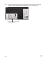
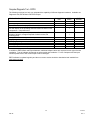
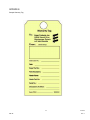
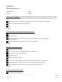
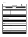
Warranty Manual Espar Products, Inc. Tel: 905.670.0960 800.387.4800 Fax: 905.670.0728 www.espar.com 1 QSF-60 02.2014 Rev. 7 Table of Contents Policies Warranty Policy Overview ............................................................................................................................. 3 Warranty Period ............................................................................................................................................ 4 What IS and IS NOT covered under Warranty? ............................................................................................ 5 Heater Identification Plate ............................................................................................................................. 6 Warranty Registration .................................................................................................................................... 8 Dealer Requirements to perform Warranty Repairs ...................................................................................... 9 Procedures Procedure prior to starting Warranty work .................................................................................................. 10 Procedure for performing Warranty work .................................................................................................... 11 Procedure for submitting Warranty claims .................................................................................................. 12 Espar’s internal procedure for processing Warranty claims ........................................................................ 14 Warranty Notification Form .......................................................................................................................... 14 Warranty Authorization (WA) ....................................................................................................................... 14 Warranty Evaluation (WE) ........................................................................................................................... 15 “Always Repair Heater” Policy..................................................................................................................... 16 Procedure for submitting a heater to Espar for Repair (RR) ....................................................................... 16 New, Defective Parts or Heaters ................................................................................................................. 17 Procedure for Returning Defective Goods (RA) .......................................................................................... 17 Procedure for Warranty appeal ................................................................................................................... 18 Flat Rate Labor Guide Flat Rate Labor Guide ................................................................................................................................. 19 AIRTRONIC 2/4 ........................................................................................................................................... 20 B1LC Compact ............................................................................................................................................ 22 B/D3LC Compact ........................................................................................................................................ 24 AIRTRONIC 5 .............................................................................................................................................. 26 D8LC ........................................................................................................................................................... 28 HYDRONIC 4/5 SC with integrated fuel metering pump ............................................................................. 30 HYDRONIC 4/5 SC with external fuel metering pump ................................................................................ 32 HYDRONIC 5 S ........................................................................................................................................... 34 HYDRONIC 5 Z ........................................................................................................................................... 36 HYDRONIC II (D5E) .................................................................................................................................... 38 HYDRONIC 10 ............................................................................................................................................ 40 HYDRONIC MII ........................................................................................................................................... 42 HYDRONIC 16/24/30/35 ............................................................................................................................. 44 HYDRONIC LII ............................................................................................................................................ 46 Tools and Equipment Computer Diagnostic Tools ......................................................................................................................... 49 Appendices Appendix A: Appendix B: Appendix C: Appendix D: Appendix E: Appendix F: The Espar Limited Warranty .................................................................................................. 50 Sample Warranty Tag ............................................................................................................ 51 Sample Shipping Label .......................................................................................................... 52 Warranty Notification Form .................................................................................................... 53 Technician’s Checklist ........................................................................................................... 54 Warranty Claim Appeal Form ................................................................................................. 55 2 QSF-60 02.2014 Rev. 7 Warranty Policy Overview The purpose of Espar warranty is to ensure that the end-user (customer) of Espar Products is satisfied with the quality of their purchase. In order to provide customer satisfaction, Espar stands behind its products as they leave Espar’s control. This Espar Warranty Manual and all policies and procedures within it, supersedes all previous warranty manual revisions. It will remain valid until a new manual is released or until further notice. Any requests for dealer labour rate increases must be made in writing and forwarded to the Warranty Department. Approval or denial will be decided upon review with the decision communicated back to the dealer. While the warranty is applicable to the end-user, it is administered and performed only through the Espar network of trained dealers and distributors. To this end, Espar will follow the procedures outlined in this manual in the processing and administration of warranty claims. For specific information please refer to the Espar Limited Warranty section as outlined in Appendix A of this manual. 3 QSF-60 02.2014 Rev. 7 Warranty Period The warranty period of a heater is specified in years or in heater operating hours, beginning from the date of installation, whichever is reached first. Refer to “What IS and IS NOT covered under Warranty” on Page 5 of this manual. If the installation date is not made known to Espar by registering the heater within thirty (30) days of installation, or by providing proof of installation date at time of warranty claim (i.e. installation invoice or ‘in-service’ document), the warranty period will begin on the date of shipment from Espar’s North American warehouse. IMPORTANT NOTE: Heaters must be installed within one (1) year of purchase date to be eligible for warranty. Installation invoices or ‘in-service’ documents provided to Espar must include applicable model number(s) and serial number(s) of the heater(s) installed. Heaters meant for truck applications should not be transferred / installed for marine applications. Heater installation is recommended to be done by the service provider who have been trained and certified by Espar trainers. Heater self installation by customer is recommended to be inspected and certified by trained service provider to prevent denial of warranty due to installation issue. Replacement Parts All replacement parts are warranted to be free from defects in material and / or workmanship for ninety (90) days from the date of sale or the remainder of the original warranty period on the heater, whichever is greater. Special Tools Special tools (e.g. ISO Adapter, Fault Code Retrieval Device, EDiTH Adapters, etc.) are warranted to be free from defects in material and / or workmanship for twelve (12) months from the date of sale from Espar’s North American warehouse. Warranty periods by model: Air Heaters Heater Model AIRTRONIC 2 AIRTRONIC 4 AIRTRONIC 5 B1LC Compact B/D3LC Compact B/D5LC D8LC Standard Warranty Period 2 years or 2,000 hours* 2 years or 2,000 hours* 2 years or 2,000 hours* 2 years or 2,000 hours* 2 years or 2,000 hours* 1 year or 1,000 hours* 1 year or 1,000 hours* Coolant Heaters Heater Model B/D5W HYDRONIC 4 HYDRONIC 5 (S/SC/E) HYDRONIC 10 HYDRONIC MII series (M8/M10/M12) HYDRONIC 16/24/30/35 HYDRONIC LII series (L16/L24/L30/L35) Standard Warranty Period 2 years or 2,000 hours* 2 years or 2,000 hours* 2 years or 2,000 hours* 1 year or 1,000 hours* 2 years or 1,500 hours* 1 year or 1,000 hours* 1 year or 1,000 hours* * which ever is reached first 4 QSF-60 02.2014 Rev. 7 What IS and IS NOT Covered Under Warranty The purpose of Espar Warranty is to provide the end user (customer) of Espar heaters with protection from defects in material and workmanship. A. Items covered under warranty include: PARTS 1. Timers, thermostats, mini-controllers or other electronic temperature control products provided by Espar 2. Electronic control units (ECU’s) 3. Glow pins 4. Fuel metering pumps 5. Heat exchangers and / or combustion chambers (burner) 6. Air blowers 7. Coolant pumps 8. Flame, overheat and temperature sensors 9. O-rings, gaskets, seals (excluding HYDRONIC D5SC coolant pump and sensor O-rings) 10. Wire harnesses (only those provided by Espar are warranted) but prior authorization is required from Espar’s Warranty Department SERVICE 1. Shipping costs associated with the authorized return of warranted parts from the Espar Dealer / Distributor to Espar (only for shipments that contain parts specifically requested by Espar). 2. To receive travel time to repair heaters installed on boats and / or off-highway heavy equipment, the travel section must be completed on the warranty claim for consideration of payment. Note that maximum limits do apply. B. Items NOT covered under warranty include but are not limited to: PARTS 1. Heaters no longer covered within terms of warranty 2. Wear and tear of parts, including: a) Glow plugs b) O-rings (HYDRONIC D5SC coolant pump and sensor O-rings) c) Clamps, clips, brackets d) Batteries e) Coolant f) Atomizer screens g) Fuel system components (e.g. fuel pick-up pipe, fuel line, filters, etc.) h) Fuses i) Connectors, terminals and screws j) Lamp bulbs k) Air ducting, intake and exhaust tubing 3. Parts that malfunction due to improper installation, which may result from: a) Inadequate air or coolant flow b) Inadequate or restricted fuel flow c) Inadequate voltage due to improper wiring upon installation d) Inadequate protection from shock or vibration e) Inadequate protection from road spray or weather conditions 4. Components that have been opened, tampered with or modified by parties other than Espar 5. Using non-standard parts or parts not approved by Espar, in the installation 5 QSF-60 02.2014 Rev. 7 6. Diagnosis or repairs completed when cause of the problem or failure is due to electrical system problems outside the heater, excessive engine debris or empty fuel tanks or poor quality fuel. 7. Deterioration due to normal wear, corrosion, abuse, damage, accident, improper storage or operation. 8. Costs incurred through an incorrect diagnosis, poor performance of the repair. This also applies to corrections of installations that did not meet Espar specifications. In these cases the costs incurred are to be charged to original installer. SERVICE 1. Travel time by dealers / distributors traveling within their assigned territories except as noted in Service section A, above, item #2. 2. Shipping costs associated with the unauthorized return of warranted parts from the Espar Dealer / Distributor to Espar Products. 3. Espar will not pay for return shipping costs to the Dealer / Distributor where parts are deemed acceptable after testing. Normal periodic heater maintenance (as outlined in each heater manual) shall be the responsibility of the owner of the heater. As a general guideline, the heater should be run a minimum of once per month for fifteen (15) minutes all year round. Heater Identification Plate The heater identification plate provides all the heater information, which is required when filing a warranty claim, such as heater model type, part number and serial number. This information must be included on every warranty claim, so be sure to record it before any warranty repair work is completed. Claims without serial numbers are subject to rejection. Model Name: AIRTRONIC, HYDRONIC or three or four digit heater model name (e.g. D5LC) In a three or four digit name, the following explanation may be helpful in understanding the heater model name: First digit indicates fuel type ....................................... Alpha (D = diesel, B = gasoline) Second digit indicates kilowatt heat output ................ Numeric (5 = 5 kilowatt, etc.) Third digit indicates type of heater ............................. Alpha (L = air heater, W = coolant heater) Fourth digit provides further designation .................... Alpha (C = comfort, etc.) .................. Heater model name .................. Heater model name .................. Heater model part number .................. Heater serial number .................. Fuel type .................. Electrical power consumption .................. Maximum heat output .................. Operating pressure 6 QSF-60 02.2014 Rev. 7 NOTE: It is strongly advised that during the heater installation the duplicate heater serial number label is affixed in a clearly visible and easily accessible location, such as on the driver door. Duplicate heater identification plate or “serial number label” 7 QSF-60 02.2014 Rev. 7 Warranty Registration A blue warranty registration notification is shipped with every heater. Please note there are several important reasons why the warranty should be registered. If a warranty registration is not received by Espar, the heater warranty period begins on the date the heater is shipped from Espar’s North American warehouse. When the warranty is properly registered, Espar can identify the date on which the heater was installed and / or put into service and therefore begin the heater warranty period on that date. This effectively extends the warranty period of the heater to the maximum time available. Registering the warranty also serves the purpose of identifying the purchaser and original installation of the heater since the warranty is non-transferable. It also identifies the installing dealer so, if required and if necessary, any installation related problems could be brought to the attention of the installer. Espar recommends all dealers / distributors register their customers’ warranty within thirty (30) days of installation by completing and submitting registration form via the internet on Espar’s website, www.espar.com. Click on the ‘Warranty’ link, then on the ‘Warranty Registration Coupon’ link to access the warranty registration. Again, it is in the customer’s best interest that the warranty be registered to receive the full warranty period allotted for their particular heater. IMPORTANT NOTE: If the warranty registration is not completed and received by Espar within thirty (30) days of installation the heater warranty period begins from the date the heater is shipped from Espar’s warehouse, unless other information is provided to Espar, upon request. 8 QSF-60 02.2014 Rev. 7 Dealer Requirements to Perform Warranty Repairs To conduct warranty repairs and submit warranty claims, the following criteria must be met: 1. Possess and maintain certified technician’s who have undergone Espar technical training (installation, diagnosing and troubleshooting) and warranty training. 2. Possess all tools required to install, maintain and service Espar products as outlined in the ‘Tools and Equipment’ section of Espar manuals. 3. Possess at all times at least one copy of the current Espar Warranty Manual and all applicable heater service manuals. The latest Espar Warranty Manual is available by downloading directly from Espar’s website, www.espar.com. 4. Maintain sufficient inventory of parts, based on heater type serviced. In order to access the Espar on-line Warranty Claim Form, at www.espar.com, and to submit a warranty claim, Espar will provide a user name and password after all required information has been received. At that time, the hourly labor rate is agreed upon and it is frozen for one year. Espar’s Warranty Administrators must be notified in writing of a labor rate increase. Approval or denial will be decided upon review and a decision will be communicated back to the dealer by the Warranty Administrator in e-mail format. 9 QSF-60 02.2014 Rev. 7 Procedure Prior to Starting Warranty Work As a member of the Espar distribution organization, you are expected to stand behind your work. This includes properly specifying and installing heaters and instructing your customers on the proper operation and maintenance of the heater and all related components or accessories. All heater technical manuals are available for download at Espar’s website, www.espar.com. Before starting any warranty repairs on the heater, please check, as appropriate and as suggested in the ‘Technician’s Checklist’, Appendix E: 1. Electrical System a) Are connections tight and free of corrosion? b) Has proper gauge wiring been used for the length and amperage requirements for that wiring? c) Have any fuses or circuit breakers been activated? d) Is power taken directly from the batteries and ground to the batteries? 2. Fuel System a) Have proper diameter fuel lines been used? b) Have proper length fuel lines been used? c) Has a proper connection to the fuel supply been made? d) Is the fuel flowing or has it gelled? e) Are there restrictions in the fuel line? f) Is the fuel metering pump properly aligned? g) Is the fuel filter clogged? h) Has an Espar fuel pick-up pipe been used and is it the proper length and diameter? 3. Coolant Flow or Air Flow System a) Are there any obstructions in the system? b) Is the heater system too large or small for the application? c) Has proper coolant hose size or ducting size been used? 4. Total operating hours to-date (with EDiTH diagnostics). 10 QSF-60 02.2014 Rev. 7 Procedure for Performing Warranty Work As a member of the Espar distribution organization you are trained in the installation, troubleshooting and repair of Espar heaters and systems and you have all of the necessary tools required to properly diagnose heater functions. Technical publications such as Technical Descriptions, Troubleshooting Guides and Parts Manuals are available by downloading directly from Espar’s website, www.espar.com. Technical circulars are issued periodically from Espar’s Technical Department. It is important to refer to current publications while working on a heater. Special tools and test equipment are available for some heaters. Refer to the Tools and Equipment section. If you have any questions, contact Espar’s Technical Department. Once you have examined the heater for system or installation problems, as set forth in the preceding section and have determined that warranty work must be performed, follow the technical publications and use your training and experience to correct the cause of the problem. IMPORTANT NOTE: Always ensure that the root cause of the problem is corrected, rather than simply correcting the symptoms of the problem. For example: if a heater has overheated several consecutive times and has been locked out (F15), do not simply reset the heater with the diagnostic unit. Locate the source of the overheat problem and correct it. Any part replaced under warranty must be tested as per the current heater manuals test procedures to confirm that it is defective before it is claimed. Parts that should be tested are, but not limited to: a) b) c) d) e) f) g) h) i) Glow pins Control units Fuel metering pumps Temperature, flame and overheat sensors Combustion air blowers Coolant pumps Thermostats and timers Mini-controllers Wire harnesses Espar assumes that the technical repair is carried out without fault and economically, (i.e. replacement of only those parts that are defective, settlement of only those labor costs incurred) according to the Flat Rate Labor Guide. Duplicate expenses, for example, two journeys because the spare part was not available, cannot be claimed. 11 QSF-60 02.2014 Rev. 7 Procedure for Submitting Warranty Claims IMPORTANT NOTE: After the warranty work has been performed and the heater is operating properly and it has been determined that the problems were truly warranty problems and not due to improper application specification, installation or operation; the procedure is as follows: 1. Affix the Espar Warranty Tag to all claimed parts. Fill out all the information indicated on the tag: Dealer Stamp, Dealer Claim Number, Espar Part Number, Part Description, Heater Name, Heater Part Number, Serial Number, Description of Defect and WE#. Each part must be held for thirty (30) days after the claim has been filed. Espar reserves the right to inspect any or all parts, upon request. If any of these parts are not requested back by Espar after the thirty (30) day period, the part may be disposed of. Supplies of Warranty Tags (Appendix B) are supplied by Espar upon request and are distributed through the main Espar authorized service branch. IMPORTANT NOTE: Should Espar request parts back, a WE# will be issued to the dealer. It is important to receive all requested parts back as warranty claims are reviewed either at Espar or its parent company, Eberspaecher. It is imperative that defective parts are available for testing and evaluation. 2. A warranty claim must be submitted within thirty (30) days of the date of repair. IMPORTANT NOTE: If a new part is determined to be defective within ninety (90) days after installation, a warranty claim should be filed as usual and the description of the problem should clearly state ’90 day warranty’. This coverage will even apply should the heater be out of warranty however, no handling, labor or travel will apply in this case. 3. To file a warranty claim go to Espar’ website, www.espar.com and click the ‘Warranty’ link and then click on the ‘Warranty Claim’ link. Only authorized Espar dealers can submit warranty claims through the secured area of the Espar website. 4. Complete all information including: a) Claimant information b) Espar MSD or Direct Dealer claim number c) Warranty authorization number (WA#), refer to Page 14 of this manual d) Heater model number e) Heater model part number (e.g. 25 1976) f) Heater serial number (“Fabrik No.”) including all alpha-numeric digits (e.g. 123456AE) g) Voltage (12V or 24V) h) Repair date i) Application type j) Vehicle information (model, type and VIN) k) Installation date and registered owner information, including name and address IMPORTANT NOTE: Warranty claims that are inaccurate (information does not correspond to the information received for the warranty registration or sales record at Espar) will be on hold pending the information required for clarification. If required information is not received within ten (10) day the associated claim will be rejected. 5. Describe the problem and repair in detail in the ‘Description of Problem’ section; it is mandatory to include all fault codes, testing procedures and values. Note that the description of the troubleshooting should correspond to the relevant fault codes entered in the fields specified. 12 QSF-60 02.2014 Rev. 7 6. Each claim automatically receives thirty (30) minutes of troubleshooting, Operation Code A and thirty (30) minutes for heater function testing, Operation Code D. 7. In ‘Parts Required for Repair’ section, indicate the quantity and choose Espar part number and description. 8. Choose the applicable operation code and labor times as per the applicable Flat Rate Labor Guide. Example: The AIRTRONIC D2 appears to start normally but then it shuts down and attempts to restart. The diagnostic fault codes in memory are: AF 64; F1 64; F2 64 and F3 64. The flame sensor was removed, tested and found to be defective, an open circuit. The operations performed, according to the Flat Rate Labor Guide were: A ................ Troubleshoot ........................ 30 minutes B230 .......... Replace flame sensor .......... 10 minutes D ................ Function test ........................ 30 minutes 70 minutes Total Time 9. Indicate the total operating hours, to-date with EDiTH diagnostics. 10. To receive travel time for repair for heaters installed on boats and off-highway heavy equipment, the travel section must be completed on the warranty claim for consideration of payment. Note that maximum limits do apply. IMPORTANT NOTE: Espar must receive the warranty claim within thirty (30) days of the date of heater repair. Claims submitted 30-60 days from the date of repair will not include an additional 20% markup on parts for part handling. Claims submitted more than sixty (60) days from the date of repair will be rejected. There will be no exceptions made. 13 QSF-60 02.2014 Rev. 7 Espar’s Internal Procedure for Processing Warranty Claims Espar will make every effort to process warranty claims promptly providing all information is provided as set out in this manual. Thus, Espar is committed to issuing credit for processed warranty claims within thirty (30) days of receiving back the requested parts. Warranty Notification Form It is the dealer’s responsibility to respond to the warranty notice (Appendix D) within ten (10) business days. If there is no response within this time period, Espar will permanently close and reject the claim. Espar will not reopen this claim once this process has been completed. When a warranty claim is processed, according to Espar’s existing warranty policy, the Dealer submitting the claim and / or MSD or DD will receive notification based upon the following criteria: 1. Warranty claim is on-hold Extra information is required by Espar to process the warranty claim. 2. Adjustments were made to the submitted warranty claim Labor time / rate requested was incorrect, duplicate labor codes, authorization for excess time, labor or parts were not requested or installation date was incorrect. 3. Rejection of the warranty claim The heater warranty period has expired; parts returned were tested and found to be not defective; parts claimed were not covered under warranty; inadequate parts return; duplicate warranty claim; vehicle owner is not the original registered owner; requested information not returned within ten (10) business days; or unauthorized WA# used for warranty claim that was not approved for a particular serial number, etc. 4. Acceptance of the warranty claim The claim submitted meets all of the necessary criteria and is being processed. See Appendix D for the notice form. Warranty Authorization (WA) A warranty authorization number (WA#) will be issued only for claims that are abnormal or outside the normal scope of the warranty manual. Please refer to the Flat Rate Labor Guide for the particular heater in question to see the additional parts that are allowable under certain conditions. These are identified by the shaded areas on the Flat Rate Labor Guide. Please request this WA# PRIOR to submitting any claim by sending an email to Espar’s Warranty Administrator for authorization. The email must include the serial number of the heater, the end user (customer’s) name, a detailed description of the problem and tests performed and the main reason for the request. The WA request will be approved or rejected by the Warranty Department at their discretion based on the supplied information. The warranty authorization number (WA#) issued by Espar pertains to one specific instance only and is to be used when submitting the claim on-line. It is not a generic number to be used liberally and if used as such will result in immediate warranty claim rejection. 14 QSF-60 02.2014 Rev. 7 Warranty Evaluation (WE) Every claimed part must be tagged and held for thirty (30) days following the submission of a warranty claim. During this time frame Espar may request that a part or heater be returned to Espar for evaluation. In this case the following procedures will apply: 1. When requesting parts and / or heaters back for evaluation, associated with a warranty claim, the Warranty Administrator will issue a Warranty Evaluation (WE) reference number and contact the customer of record (authorized Espar MSD / Direct Dealer) via email. It is the responsibility of the MSD / DD to distribute this number to their sub-dealers. Upon receiving a WE# all parts corresponding to the given WE# must be returned within thirty (30) days. IMPORTANT NOTE: If the part is not received within this time frame the corresponding claim will receive no handling. If the part is still not received within the following thirty (30) days, the claim will be rejected and closed permanently. 2. All paperwork and packaging must reference the WE number to avoid rejection. When any product is returned without a WE number there will be a $50.00 administration charge to your account. No exceptions will be made. 3. Parts and heaters must be packaged securely to avoid damage in transit, as damaged parts / heaters are not covered under warranty. 4. Ship via UPS ground. Air shipments will not be paid for by Espar. 5. All parts and heaters must be marked clearly with a completed warranty tag (refer to Appendix B). Parts that are not tagged will not be tested, which will result in automatic claim rejection. Parts can be returned to the dealer at their cost. Proper documentation must accompany each shipment, which includes: shipping labels marked clearly with Espar reference numbers, affixed to the outside of the package (refer to Appendix C). Canadian Customers ONLY Ship to: Warranty Department Espar Products, Inc. 6099A Vipond Drive Mississauga, Ontario L5T 2B2 CANADA Espar Reference Number (WE# assigned to you) U.S. Customers ONLY Ship to: Warranty Department Espar Products, Inc. 60 Industrial Parkway, Suite 730 Cheektowaga, New York 14227 USA Espar Reference Number (WE# assigned to you) NOTE: Tested parts found not to be defective can be returned to a dealer at their request and cost. All parts are disposed by Espar thirty (30) days after the disposition of the claim has been sent to the dealer. 15 QSF-60 02.2014 Rev. 7 “Always Repair Heater” Policy Espar and Eberspaecher have an “Always Repair Heater” policy. In the case that a Main Service Distributor or Dealer has difficulty in diagnosing and repairing a heater they should contact Espar’s Technical Department for further assistance. After consulting with Espar and providing that it is within its warranty period and Espar has deemed it necessary to have the heater returned, Espar will issue an RR#. This will authorize the heater to be shipped to Espar for repair. A replacement heater should not be permanently issued to the customer prior to Espar assisting with the correct diagnosis of the heater in question. Procedure for Submitting a Heater to Espar for Repair Purposes (RR) 1. A request must be made to Espar’s Warranty Supervisor or Technical Department. 2. Espar’s Warranty Supervisor or Tech Department will issue a “Repair / Rework” (RR) number. 3. The product may then be returned to Espar with the RR number clearly marked on the shipping label (refer to Appendix C) and package(s). All costs associated with shipping the heater to Espar will be the responsibility of the dealer or heater owner. Parts and heaters must be packaged securely to avoid damage in transit. Parts damaged due to this will not be covered under warranty. Proper documentation must accompany each shipment, which includes: shipping labels marked clearly with Espar reference numbers, where applicable and affixed to the outside of the package (Refer to Appendix C). 4. Upon receipt, the heater will be tested and if possible, repaired. If the heater can not be repaired and it is still under warranty, it will be replaced at Espar’s expense. A replacement heater will be warranted for ninety (90) days or the balance of previous heater’s warranty, which ever is longer. 5. The repaired heater, or new heater, when applicable, will be returned to the dealer or MSD. Shipping costs (UPS ground) of the return heater to the Dealer or MSD will be covered by Espar. 6. If a heater is returned without an RR number, there will be a $50.00 administration charge to your account. No exceptions will be made. In addition, heaters returned with proper authorization will receive the highest priority for repair. Canadian Customers ONLY Ship to: Warranty Department Espar Products, Inc. 6099A Vipond Drive Mississauga, Ontario L5T 2B2 CANADA Espar Reference Number (RR# assigned to you) U.S. Customers ONLY Ship to: Warranty Department Espar Products, Inc. 60 Industrial Parkway, Suite 730 Cheektowaga, New York 14227 USA Espar Reference Number (RR# assigned to you) 16 QSF-60 02.2014 Rev. 7 New Defective Parts or Heaters (when they are NOT covered under warranty) If a new part or heater is determined to be defective by visual inspection, or found to be functionally defective immediately, prior to installation, it should be returned to Espar using a Return Goods Authorization Policy (RGA). New defective parts or heaters can not be claimed as warranty. Procedure for Returning Defective Goods (RGA) 1. A faxed copy of the original invoice or packing slip (with the new, defective part or heater listed on it must be submitted to the attention of Espar’s Customer Service Department). Verbal requests will not be accepted or processed. 2. Espar’s Customer Service staff will then fax back a Return Goods Authorization (RGA) number. 3. The product may then be returned to Espar with a copy of the Return Goods Authorization (RGA) form enclosed. 4. Parts and heaters must be packaged securely to avoid damage in transit. 5. Ship via UPS ground. Air shipments will not be paid for by Espar. 6. Proper documentation must accompany each shipment, which includes: shipping labels marked clearly with Espar RGA, affixed to the outside of the package (refer to Appendix C). Canadian Customers ONLY Ship to: Customer Service Department Espar Products, Inc. 6099A Vipond Drive Mississauga, Ontario L5T 2B2 CANADA Espar Reference Number (RGA# assigned to you) U.S. Customers ONLY Ship to: Customer Service Department Espar Products, Inc. 60 Industrial Parkway, Suite 730 Cheektowaga, New York 14227 USA Espar Reference Number (RGA# assigned to you) 7. Upon receipt, the product will then be inspected and a credit will be processed to the customer of record, MSD or DD, or may be refused if testing concludes the product is functional. If the product has been found to be used (installed) the RGA will be rejected and no warranty claim will be accepted. 8. When any product is returned without an RGA number there will be a $50.00 administration charge to your account. No exceptions will be made. 17 QSF-60 02.2014 Rev. 7 Procedure for Warranty Appeal It is Espar’s intent to close all claims within thirty (30) days after parts are returned and claim process is completed. The warranty appeal must be filed within thirty (30) days of claim rejection issue date in order to receive consideration for reversal. IMPORTANT NOTE: Appeals will not be considered for claims that have aged beyond thirty (30) days of final rejection issue date and closed permanently. Warranty Appeal Process 1. The claim outcome is communicated to the MSD or Dealer with the appeal document (refer to Appendix F). 2. The Dealer files an appeal to Espar through the Warranty Administrator. This must be within thirty (30) days from the claim outcome that was communicated. 3. The Warranty Technologist re-opens the claim for processing. 4. The Warranty Technologist re-evaluates the claim based on the new information from the appeal. 5. If there is a warranty returned part involved in the appeal, the Warranty Technician will re-test the part again and document the test results. 6. Based on the outcome of the report of the second test, the final disposition will be communicated to the MSD or Dealer and the claim will be closed. 18 QSF-60 02.2014 Rev. 7 Espar Flat Rate Labor Guide This Flat Rate Labor Guide has been developed and based on the worldwide experience of Espar and Eberspaecher service centers. This guide is organized by heater model in order of heat output. When submitting a warranty claim, it is mandatory to log a detailed description of the repair. The description you provide should correspond with the fault codes indicated. It is imperative to verify replaced parts as failed parts. IMPORTANT NOTE: Espar and Eberspaecher have an “Always Repair Heater” policy. 19 QSF-60 02.2014 Rev. 7 AIRTRONIC 2 / 4 For Heater Model Numbers: 12V AIRTRONIC D2 25 2069 AIRTRONIC D4 25 2113 AIRTRONIC B4 20 1812 Diagram Reference Number 24V 25 2070 25 2114 Part Description Operation A. Troubleshoot B. Components Replaced with Heater Installed 1 Electronic Control Unit (ECU) 2 Combi-Sensor (Overheat / Flame) 3 Glow Pin with Tool 4 Fuel Metering Pump 5 Mini-Controller 6 Thermostat 7 Rheostat 8 7-Day Timer Digi-Max 9 Main Wire Harness 9 Main Wire Harness 10 Heat Exchanger / Burner C. Components Replaced with Heater Removed 11 Blower Unit 12 Burner / Flame Tube 13 Gasket, Blower 14 Gasket, Burner D. Heater Function Test Replace Replace Replace Replace Replace Replace Replace Replace Replace Repair Replace Clean Replace Replace Replace Replace 20 QSF-60 Flat Rate Labor Code A Time Allowance (minutes) A-B180 A-B230 A-B310 A-B480 A-B540 A-B545 A-B550 A-B565 A-B572 A-B580 A-B520 A-B010 A-C000 A-C100 A-C050 A-C145 A-C080 D 10 10 10 10 15 15 10 15 10 30 30 15 60 10 20 15 10 30 Warranty Authorization Number (WA#) Required 30 02.2014 Rev. 7 AIRTRONIC 2 / 4 21 QSF-60 02.2014 Rev. 7 B/D1LC Compact For Heater Model Numbers: 12V B1LC Compact 20 1766 D1LC Compact 25 1976 Diagram Reference Number Part Description Operation A. Troubleshoot B. Components Replaced with Heater Installed 1 Electronic Control Unit (ECU) 2 Fuel Metering Pump 3 Mini-Controller 4 Thermostat 5 Rheostat 6 7-Day Timer 7 Seal, Glow Plug 8 Battery Wire Harness 9 Switch Wire Harness 10 Fuel Metering Pump Wire Harness 11 Main Wire Harness 11 Main Wire Harness Replace Replace Replace Replace Replace Replace Replace Replace Replace Replace Repair Replace C. Components Replaced with Heater Removed 12 Blower Unit 13 Overheat Sensor 14 Flame Sensor 15 Seal Ring, burner 16 Gasket, blower 17 Gasket, burner 18 Heat Exchanger / Burner 18 Heat Exchanger / Burner D. Heater Function Test Replace Replace Replace Replace Replace Replace Replace Clean 22 QSF-60 Flat Rate Labor Code A Time Allowance (minutes) D1-B180 D1-B480 D1-B540 D1-B545 D1-B550 D1-B565 D1-B330 D1-B525 D1-B530 D1-B535 D1-B580 D1-B520 10 10 15 15 10 15 10 15 15 15 10 10 D1-C000 60 D1-C100 D1-C255 D1-C280 D1-C085 D1-C145 D1-C080 D1-C005 D1-C010 D 15 15 15 20 15 20 25 15 30 Warranty Authorization Number (WA#) Required 30 02.2014 Rev. 7 B/D1LC Compact 23 QSF-60 02.2014 Rev. 7 B/D3LC Compact For Heater Model Numbers: 12V D3LC Compact 25 1981 Diagram Reference Number 24V Part Description Operation A. Troubleshoot B. Components Replaced with Heater Installed 1 Electronic Control Unit (ECU) 2 Fuel Metering Pump 3 Mini-Controller 4 Thermostat 5 Rheostat 6 7-Day Timer 7 Seal, Glow Plug 8 Battery Wire Harness 9 Switch Wire Harness 10 Fuel Metering Pump Wire Harness 11 Main Wire Harness 11 Main Wire Harness C. Components Replaced with Heater Removed 12 Blower Unit 13 Overheat Sensor 14 Flame Sensor 15 Seal Ring, burner 16 Gasket, blower 17 Gasket, burner 18 Heat Exchanger / Burner 18 Heat Exchanger / Burner D. Heater Function Test Replace Replace Replace Replace Replace Replace Replace Replace Replace Replace Repair Replace Replace Replace Replace Replace Replace Replace Replace Clean 24 QSF-60 Flat Rate Labor Code A Time Allowance (minutes) D3-B180 D3-B480 D3-B540 D3-B545 D3-B550 D3-B565 D3-B330 D3-B525 D3-B530 D3-B535 D3-B580 D3-B520 D3-C000 D3-C100 D3-C255 D3-C280 D3-C085 D3-C145 D3-C080 D3-C005 D3-C010 D 10 10 15 15 10 15 10 15 15 15 10 10 60 15 15 15 20 15 20 25 15 30 Warranty Authorization Number (WA#) Required 30 02.2014 Rev. 7 B/D3LC Compact 25 QSF-60 02.2014 Rev. 7 AIRTRONIC 5 For Heater Model Numbers: 12V AIRTRONIC B5 20 1859 AIRTRONIC D5 25 2361 Diagram Reference Number 24V 25 2362 Part Description Operation A. Troubleshoot B. Components Replaced with Heater Installed 1 Remote Temperature Sensor 2 Fuel-Metering Pump 3 Mini-Controller 4 Thermostat 5 Rheostat 6 7 Day Timer Digi-Max 7 Main Wire Harness 7 Main Wire Harness Replace Replace Replace Replace Replace Replace Replace Repair Replace C. Components Replaced with Heater Removed 8 Cable, Glow Plug 9 Combi-Sensor (Overheat / Flame) 10 Blower Unit 11 Seal Ring, burner 12 Cover, burner 13 Gasket, blower 14 Gasket, burner 15 Heat Exchanger / Burner 15 Heat Exchanger / Burner D. Heater Function Test Replace Replace Replace Replace Replace Replace Replace Replace Clean 26 QSF-60 Flat Rate Labor Code A Time Allowance (minutes) A5-B180 A5-B480 A5-B540 A5-B545 A5-B550 A5-B565 A5-B572 A5-B580 A5-B520 10 10 15 10 15 15 10 30 30 A5-C000 60 A5-C345 A5-C230 A5-C100 A5-C085 A5-C090 A5-C145 A5-C080 A5-C005 A5-C010 D 15 20 20 25 25 15 20 30 15 30 Warranty Authorization Number (WA#) Required 30 02.2014 Rev. 7 AIRTRONIC 5 27 QSF-60 02.2014 Rev. 7 D8LC For Heater Model Numbers: 12V D8LC 25 1890 Diagram Reference Number 24V 25 1891 Part Description Operation A. Troubleshoot B. Components Replaced with Heater Installed 1 Printed Circuit Board 2 Electronic Control Unit (ECU) 3 Overheat Switch 4 Temperature Sensor 5 Air-Solenoid Valve 6 Fuel Metering Pump 7 Thermostat 8 Rheostat 9 Remote Temperature Sensor 10 7-Day Timer Digi-Max 11 Main Wire Harness 11 Main Wire Harness 12 Glow Plug Relay 13 Relay 14 Cover, Component Box Housing 15 Internal Main Wire Harness C. Components Replaced with Heater Removed 16 Blower Unit 17 Flame Sensor 18 Gasket, Burner 19 Fan Wheel, Blower Unit 20 Housing, Blower Unit 21 Component Box housing with Seal 22 Heat Exchanger / Burner 22 Heat Exchanger / Burner D. Heater Function Test Replace Replace Replace Replace Replace Replace Replace Replace Replace Replace Replace Repair Replace Replace Replace Replace Replace Replace Replace Replace Replace Replace Replace Replace Clean 28 QSF-60 Flat Rate Labor Code A Time Allowance (minutes) D8-B175 D8-B180 D8-B270 D8-B305 D8-B380 D8-B480 D8-B545 D8-B550 D8-B555 D8-B565 D8-B572 D8-B580 D8-B520 D8-B355 D8-B390 D8-B435 D8-B510 D8-C000 D8-C100 D8-C280 D8-C080 D8-C130 D8-C135 D8-C430 D8-C005 D8-C010 D 10 10 10 10 10 10 15 10 15 15 10 30 30 5 5 5 15 60 35 30 15 15 35 20 45 20 30 Warranty Authorization Number (WA#) Required 30 02.2014 Rev. 7 D8LC 29 QSF-60 02.2014 Rev. 7 HYDRONIC 4 / 5 SC (Integrated Coolant Pump, Integrated Fuel Metering Pump) For Heater Model Numbers: 12V HYDRONIC D5 25 2219 Diagram Reference Number Part Description Operation A. Troubleshoot B. Components Replaced with Heater Installed 1 Electronic Control Unit (ECU) 2 Push / Pull Switch 3 7-Day Timer 4 Thermostat Multi-Max 5 Main Wire Harness 5 Main Wire Harness C. Components Replaced with Heater Removed 6 Blower Unit 7 Coolant Pump 8 Overheat Sensor with Cable Section 9 Flame Sensor 10 Glow Pin 11 Fuel Metering Pump 12 Burner / Flame Tube 13 O-Ring, Heat Exchanger 14 Seal Kit 15 Heat Exchanger 16 Fuel Connection, Glow Pin D. Heater Function Test Replace Replace Replace Replace Replace Repair Replace Replace Replace Replace Replace Replace Replace Replace Replace Replace Clean Replace 30 QSF-60 Flat Rate Labor Code A Time Allowance (minutes) H1-B180 H1-B560 H1-B565 H1-B545 H1-B573 H1-B580 H1-B520 H1-C000 H1-C100 H1-C200 H1-C240 H1-C280 H1-C310 H1-C480 H1-C050 H1-C020 H1-C081 H1-C010 H1-C315 D 10 10 15 15 10 30 30 60 20 15 25 15 15 20 25 30 25 15 20 30 Warranty Authorization Number (WA#) Required 30 02.2014 Rev. 7 HYDRONIC 4 / 5 SC (Integrated Coolant Pump, Integrated Fuel Metering Pump) 31 QSF-60 02.2014 Rev. 7 HYDRONIC 4 / 5 SC (Integrated Coolant Pump, External Fuel Metering Pump) For Heater Model Numbers: 12V HYDRONIC D4 20 1824 HYDRONIC B5 20 1820 HYDRONIC D5 25 2325 Diagram Reference Number 24V 25 2147 Part Description Operation A. Troubleshoot B. Components Replaced with Heater Installed 1 Electronic Control Unit (ECU) 2 Fuel Metering Pump 3 Push / Pull Switch 4 7-Day Timer 5 Thermostat Multi-Max 6 Main Wire Harness 6 Main Wire Harness C. Components Replaced with Heater Removed 7 Blower Unit 8 Coolant Pump 9 Overheat Sensor with Cable Section 10 Flame Sensor 11 Glow Pin 12 Burner / Flame Tube 15 O-Ring, Heat Exchanger 16 Seal Kit 17 Heat Exchanger 18 Fuel Connection, Glow Pin D. Heater Function Test Replace Replace Replace Replace Replace Replace Repair Replace Replace Replace Replace Replace Replace Replace Replace Replace Clean Replace 32 QSF-60 Flat Rate Labor Code A Time Allowance (minutes) H2-B180 H2-B480 H2-B560 H2-B565 H2-B545 H2-B573 H2-B580 H2-B520 H2-C000 H2-C100 H2-C200 H2-C240 H2-C280 H2-C310 H2-C050 H2-C020 H2-C081 H2-C010 H2-C315 D 10 10 10 15 15 10 30 30 60 20 15 25 15 15 25 30 25 15 20 30 Warranty Authorization Number (WA#) Required 30 02.2014 Rev. 7 HYDRONIC 4 / 5 SC (Integrated Coolant Pump, External Fuel Metering Pump) 33 QSF-60 02.2014 Rev. 7 HYDRONIC 5 S (External Coolant Pump, External Fuel Metering Pump) For Heater Model Numbers: 12V HYDRONIC B5 20 1819 HYDRONIC D5 25 2217 Diagram Reference Number 24V 24V 25 2146 25 2218 Part Description Operation A. Troubleshoot B. Components Replaced with Heater Installed 1 Electronic Control Unit (ECU) 2 Coolant Pump 3 Fuel Metering Pump 4 Push / Pull Switch 5 7-Day Timer 6 Thermostat Multi-Max 7 Main Wire Harness 7 Main Wire Harness C. Components Replaced with Heater Removed 8 Blower Unit 9 Overheat Sensor with Cable Section 10 Flame Sensor 11 Glow Pin 12 Burner / Flame Tube 13 O-Rings, Coolant Pump 14 O-Rings, Sensors 15 O-Ring, Heat Exchanger 16 Seal Kit 17 Heat Exchanger 18 Fuel Connection, Glow Pin D. Heater Function Test Replace Replace Replace Replace Replace Repair Replace Repair Replace Replace Replace Replace Replace Replace Replace Replace Replace Replace Clean Replace 34 QSF-60 Flat Rate Labor Code A Time Allowance (minutes) H3-B180 H3-B200 H3-B480 H3-B560 H3-B565 H3-B545 H3-B573 H3-B580 H3-B520 H3-C000 H3-C100 H3-C240 H3-C280 H3-C310 H3-C050 H3-C205 H3-C245 H3-C020 H3-C081 H3-C010 H3-C315 D 10 10 10 10 15 15 10 30 30 60 20 25 15 15 25 15 15 30 25 15 20 30 Warranty Authorization Number (WA#) Required 30 02.2014 Rev. 7 HYDRONIC 5 S (External Coolant Pump, External Fuel Metering Pump) 35 QSF-60 02.2014 Rev. 7 HYDRONIC 5 Z (No Coolant Pump, External Fuel Metering Pump) For Heater Model Numbers: 12V HYDRONIC D5 25 2216 Diagram Reference Number Part Description Operation A. Troubleshoot B. Components Replaced with Heater Installed 1 Electronic Control Unit (ECU) 2 Fuel Metering Pump 3 Push / Pull Switch 4 7-Day Timer 5 Thermostat 6 Main Wire Harness 6 Main Wire Harness Replace Replace Replace Replace Replace Repair Replace C. Components Replaced with Heater Removed 7 Blower Unit 8 Overheat Sensor with Cable Section 9 Flame Sensor 10 Glow Pin 11 Burner / Flame Tube 12 O-Rings, Coolant Pump 13 O-Rings, Sensors 14 O-Ring, Heat Exchanger 15 Seal Kit 16 Heat Exchanger 17 Fuel Connection, Glow Pin D. Heater Function Test Replace Replace Replace Replace Replace Replace Replace Replace Replace Clean Replace 36 QSF-60 Flat Rate Labor Code A Time Allowance (minutes) H4-B180 H4-B480 H4-B560 H4-B565 H4-B545 H4-B580 H4-B520 10 10 10 15 15 30 30 H4-C000 60 H4-C100 H4-C240 H4-C280 H4-C310 H4-C050 H4-C205 H4-C245 H4-C020 H4-C081 H4-C010 H4-C315 D 20 25 15 15 25 15 15 30 25 15 20 30 Warranty Authorization Number (WA#) Required 30 02.2014 Rev. 7 HYDRONIC 5 Z (No Coolant Pump, External Fuel Metering Pump) 37 QSF-60 02.2014 Rev. 7 HYDRONIC II 5E (External Coolant Pump, External Fuel-Metering Pump) For Heater Model Numbers: HYDRONIC B5S HYDRONIC D5S Diagram Reference Number 12V 20 1904 25 2526 Part Description Operation A. Troubleshoot Flat Rate Labor Code Time Allowance (minutes) A 30 H5-B200 H5-B480 H5-B560 H5-B565 H5-B570 H5-B571 H5-B573 H5-B580 H5-B520 10 10 10 15 15 15 10 30 30 H5-C000 60 H5-C180 H5-C100 H5-C240 H5-C280 H5-C310 H5-C050 H5-C205 H5-C081 H5-C010 30 20 25 15 15 25 15 25 15 D 30 Warranty Authorization Number (WA#) Required B. Components Replaced with Heater Installed 1 2 3 4 5 6 7 7 Coolant Pump Fuel-Metering Pump Push/Pull Switch 7-Day Timer Programmable Timer Easy start/Mini Timer Multi-Max Main Wire Harness Main Wire Harness Replace Replace Replace Replace Replace Replace Replace Repair Replace C. Components Replaced with Heater Removed 8 9 10 11 12 13 14 15 16 Electronic Control Unit (ECU) Blower Fan Lead harness(temp & surface sensor) Flame Sensor Glow Pin Combustion Chamber O-Rings, Water pipe socket Seal Kit Heat Exchanger Replace Replace Replace Replace Replace Replace Replace Replace Clean D. Heater Function Test 38 QSF-60 • • 02.2014 Rev. 7 39 QSF-60 02.2014 Rev. 7 HYDRONIC 10 For Heater Model Numbers: 12V HYDRONIC 10 25 2160 Diagram Reference Number 24V 25 2227 Part Description A. Troubleshoot B. Components Replaced with Heater Installed 1 Electronic Control Unit (ECU) 2 Fuel Metering Pump 3 Push / Pull Switch 4 7-Day Timer 5 Thermostat Multi-Max 6 Main Wire Harness 6 Main Wire Harness Operation Replace Replace Replace Replace Replace Replace Repair Replace C. Components Replaced with Heater Removed 7 Blower Unit 8 Coolant Pump 9 Overheat Sensor 10 Flame Sensor 11 Temperature Sensor 12 Glow Pin 13 O-Ring, Coolant Pump 14 O-Ring, Overheat Sensor 15 O-Ring, Temperature Sensor 16 O-Ring, Heat Exchanger 17 Burner / Flame Tube 18 Burner with Housing 19 Heat Exchanger 20 Wire Harness, Glow Pin D. Heater Function Test Replace Replace Replace Replace Replace Replace Replace Replace Replace Replace Replace Replace Clean Replace 40 QSF-60 Flat Rate Labor Code Time Allowance (minutes) A 30 H10-B180 H10-B480 H10-B560 H10-B565 H10-B545 H10-B573 H10-B580 H10-B520 10 10 10 15 15 10 30 30 H10-C000 60 H10-C100 H10-C200 H10-C255 H10-C280 H10-C305 H10-C310 H10-C205 H10-C265 H10-C295 H10-C020 H10-C050 H10-C055 H10-C010 H10-C911 D 15 15 15 20 15 10 10 15 15 25 35 35 15 15 30 Warranty Authorization Number (WA#) Required 02.2014 Rev. 7 HYDRONIC 10 41 QSF-60 02.2014 Rev. 7 HYDRONIC MII For Heater Model Numbers: 12V HYDRONIC M8 25 2470 HYDRONIC M10 25 2434 HYDRONIC M12 25 2472 HYDRONIC M12 25 2596 Diagram Reference Number 24V 25 2471 25 2435 25 2473 Part Description A. Troubleshoot B. Components Replaced with Heater Installed 1 Coolant Pump 2 O-Ring, Coolant Pump 3 Relay Wire Harness 4 Fuel Metering Pump 5 Fuel Metering Pump Wire Harness 6 Push / Pull Switch 7 7-Day Timer 8 Programmable Timer Multi-Max 9 Main Wire Harness 10 Main Wire Harness C. Components Replaced with Heater Removed 1 Coolant Pump (boxed heater) 1 11 Burner / Flame Tube 12 Seal, Burner 2 13 Blower / Control Unit 14 O-Ring, Blower 15 Overheat / Temperature Sensor 16 Flame Sensor 3 17 Glow Pins 18 Coolant Pump Wire Harness 19 Heat Exchanger / Water Jacket 20 Heat Exchanger / Water Jacket D. Heater Function Test Operation Replace Replace Replace Replace Replace Replace Replace Replace Replace Repair Replace Replace Replace Replace Replace Replace Replace Replace Replace Replace Replace Clean Flat Rate Labor Code Time Allowance (minutes) A 30 HM-B200 HM-B205 HM-B440 HM-B480 HM-B535 HM-B560 HM-B565 HM-B570 HM-B573 HM-B580 HM-B520 HM-C000 HM-C201 HM-C050 HM-C080 HM-C150 HM-C185 HM-C241 HM-C280 HM-C310 HM-C450 HM-C006 HM-C010 D 10 10 15 10 15 10 15 15 10 30 30 60 10 70 70 75 10 35 20 70 30 45 45 30 Warranty Authorization Number (WA#) Required 1 – Burner tube replacement includes replacement of burner seal and blower O-ring 2 – Blower / control unit replacement includes replacement of blower O-ring and burner seal 3 – Glow pin replacement includes replacement of blower O-ring and burner seal 42 QSF-60 02.2014 Rev. 7 HYDRONIC MII 43 QSF-60 02.2014 Rev. 7 HYDRONIC 16 / 24 / 30 / 35 For Heater Model Numbers: 24V HYDRONIC 35 25 1819 Diagram Reference Number Part Description A. Troubleshoot B. Components Replaced with Heater Installed 1 Coolant Pump 2 Overheat Sensor 3 Temperature Sensor 4 Push / Pull Toggle Switch 5 7-Day Timer 6 Spare Part Kit, Coolant Pump Multi-Max 7 Main Wire Harness 7 Main Wire Harness 8 Combustion Air Inlet Hood 9 Internal Main Wire Harness Operation Replace Replace Replace Replace Replace Replace Replace Repair Replace Replace Replace C. Components Replaced with Heater Removed 10 Flame Tube 11 Burner Motor 12 Fuel Atomizer Nozzle 13 Heat Element Nozzle 14 Electronic Control Unit (ECU) 15 Ignition Spark Generator 16 Ignition Electrodes 17 Fuel Solenoid Coil 18 Hardware for Fuel Solenoid Coil 19 Baffle Plate / Heat Shield 20 Fuel Pump / Housing 21 Heat Exchanger / Water Jacket 21 Heat Exchanger / Water Jacket D. Heater Function Test Replace Replace Replace Replace Replace Replace Replace Replace Replace Replace Replace Replace Clean 44 QSF-60 Flat Rate Labor Code Time Allowance (minutes) A 30 LH-B200 LH-B255 LH-B305 LH-B560 LH-B565 LH-B225 LH-B573 LH-B580 LH-B520 LH-B450 LH-B510 10 10 10 10 15 20 10 30 30 10 5 LH-C000 60 LH-C050 LH-C105 LH-C165 LH-C170 LH-C180 LH-C195 LH-C335 LH-C500 LH-C505 LH-C155 LH-C495 LH-C006 LH-C010 D 5 10 10 10 10 10 10 15 15 5 20 20 20 30 Warranty Authorization Number (WA#) Required 02.2014 Rev. 7 HYDRONIC 16 / 24 / 30 / 35 45 QSF-60 02.2014 Rev. 7 HYDRONIC LII For Heater Model Numbers: HYDRONIC L16 25 2486 HYDRONIC L24 25 2487 HYDRONIC L30 25 2488 HYDRONIC L35 25 2489 Diagram Reference Number 25 2599 Part Description A. Troubleshoot B. Components Replaced with Heater Installed 1 Coolant Pump 2 Overheat Sensor 3 Temperature Sensor 4 Push / Pull Toggle Switch 5 7-Day Timer 6 Spare Part Kit, Coolant Pump Multi-Max 7 Main Wire Harness 7 Main Wire Harness 8 Combustion Air Inlet Hood 9 Internal Main Wire Harness C. Components Replaced with Heater Removed 10 Flame Tube 11 Burner Motor 12 Fuel Atomizer Nozzle 13 Heat Element Nozzle 14 Electronic Control Unit (ECU) 15 Ignition Spark Generator 16 Ignition Electrodes 17 Fuel Solenoid Coil 18 Baffle Plate / Heat Shield 1 19 Fuel Pump Kit 20 Heat Exchanger / Water Jacket 20 Heat Exchanger / Water Jacket D. Heater Function Test Operation Replace Replace Replace Replace Replace Replace Replace Repair Replace Replace Replace Replace Replace Replace Replace Replace Replace Replace Replace Replace Replace Replace Clean 46 QSF-60 Flat Rate Labor Code Time Allowance (minutes) A 30 HL-B200 HL-B255 HL-B305 HL-B560 HL-B565 HL-B225 HL-B573 HL-B580 HL-B520 HL-B450 HL-B510 HL-C000 HL-C050 HL-C105 HL-C165 HL-C170 HL-C180 HL-C195 HL-C335 HL-C501 HL-C155 HL-C490 HL-C006 HL-C010 D 10 10 10 10 15 20 10 30 30 10 5 60 5 10 10 10 10 10 10 15 5 40 20 20 30 Warranty Authorization Number (WA#) Required 02.2014 Rev. 7 HYDRONIC LII 47 QSF-60 02.2014 Rev. 7 Tools and Equipment Generally, standard shop tools are required for the installation and repair of Espar heaters. However, there are a few additional tools required for efficient troubleshooting and repair. All required tools are listed below. Required Equipment for General Heater Repair EDiTH diagnostic computer software and hardware Diagnostic unit o Previously named “Fault Code Retrieval Device” o Appropriate diagnostic wire adaptors Electrician’s crimping tool for non-insulated terminals Terminal removal tool, 1.6mm Terminal removal tool, 2.8mm 3 Graduated cylinder, range of 0 to 50cm or 0 to 50ml Torx drivers Metric Allen key wrenches Metric wrenches and / or sockets (4mm through 27mm) Fuel line cutter or knife Multi-meter For complete and thorough service of Espar heaters, the following special tools and equipment are recommended in addition to those listed above. Special Tools Graduated cylinder, range of 0 to 500cm (for HYDRONIC 16 / 24 / 30 / 35) Spark gapping gauge(s) for HYDRONIC 16 / 24 / 30 / 35 Tachometer (RPM meter), optical or digital readout preferred Stop watch Thermometer, minimum range of 0°C to 300°C (32°F to 572°F) Carbon dioxide (CO2) gas analyzer, minimum range of 0 to 20% Smoke tester 3 48 QSF-60 02.2014 Rev. 7 Computer Diagnostic Tool – EDiTH The following overview is to help you understand the capability of different diagnostic hardware. Available are: Diagnostic Unit, EDiTH Basic and EDiTH Expert. PRODUCT / FUNCTIONS Read out the current error and the latest five errors Running diagnosis at installed heaters Turn on the heater directly by PC or Notebook Visualization of the sequence of operations of the heater / control unit with display of the operating state and measured data of each components – components test Individual test of components (independent of control unit) i.e. voltage of glow pin, voltage and speed of electric motor, fuel metering pump Recognition if heater is high altitude adjustable Display of general heater data IPCU programming Recognition if the control unit is high altitude adjustable Running diagnosis on control unit Test control unit under real performance conditions DIAGNOSTIC UNIT EDiTH BASIC EDiTH EXPERT In addition to EDiTH Basic and Expert hardware, additional adapter cables are required for each type of heater installation. Type of adapters will depend on heater model and installation. For list of adaptors and their part numbers please refer to the current Espar Product Catalogue. EDiTH software is updated regularly and the most recent version should be downloaded and installed from www.espar.com/help. 49 QSF-60 02.2014 Rev. 7 APPENDIX A The Espar Limited Warranty Espar Products, Inc. (“Espar”) warrants its heaters (the “Products”) to be free from defects in materials and workmanship, subject to the terms below. Espar will, at its option, repair or replace any Products or any parts of a Product which are subject to warranty according to Espar’s Warranty Manual (the “Warranted Parts”) if such Products or Warranted Parts are proven defective in materials or workmanship during the relevant warranty period (the “Warranty Period”) described below. This is Espar’s sole obligation under this warranty. This warranty extends only to the original owner (each an “Owner”). Unless Espar agrees in writing, this warranty cannot be transferred and it only applies to a Product in its original installation. The Warranty Period is: (a) two (2) years or two thousand (2,000) operating hours (whichever comes first) for AIRTRONIC 2, AIRTRONIC 4, AIRTRONIC 5, B1LC Compact, B/D3LC Compact, HYDRONIC 4, HYDRONIC 5 and B/D5W heaters; or (b) two (2) years or one thousand five hundred (1,500) operating hours (whichever comes first) for HYDRONIC MII heaters; or (c) one (1) year or one thousand (1,000) operating hours (whichever comes first) for all other Espar heaters. The Warranty Period begins on: (a) the date of sale of equipment containing the Product by an Original Equipment Manufacturer (“OEM”) to the Owner; or (b) the date of installation for the Owner or the date of shipment by Espar, whichever is later, for all Products not sold to an Owner by an OEM. To obtain service of a Product under this warranty, present the nearest Espar authorized and trained dealer (each an “Espar Dealer”) with proof of purchase and for Products not sold by an OEM, the date of installation. To establish the date of purchase and date of installation of a Product, Owners should register for the Espar Warranty on-line at www.espar.com within thirty (30) days of the installation or purchase of the Product. If the Owner has not registered online, the Owner can submit to the Espar Dealer other reasonable proof of the dates of purchase and for Products not sold by an OEM, of production installation. If the Owner cannot prove such dates, the Warranty Period will be deemed to have started when the Product was shipped by Espar. The Espar Dealer will perform warranty service subject to this warranty and Espar’s Warranty Manual. The Espar Dealer will also complete and submit a Warranty Claim to Espar. Espar will pay only Espar Dealers or installers to remove and re-install Products and Warranted Parts according to Espar’s Warranty Manual. Espar shall not pay for any other labor costs. Depending on where and how the Product was installed, the Owner may be required to return the Product to the Espar Dealer who originally installed the Product for warranty service. The cost of this return will be paid by the Owner. When servicing according to this warranty, Espar or an Espar Dealer may replace parts with new parts and change part specifications without notice provided such replacements or changes do not adversely affect the Product’s performance. This warranty does not cover damage or defects caused by: (a) installation; (b) service; (c) the use of replacement parts which are not genuine Espar parts; (d) use of a Product for other than its intended purpose; (e) use under other than normal conditions; (f) use contrary to Espar’s instructions; (g) accident; (h) neglect; or (i) normal wear and tear on parts such as glow plugs, atomizer screens, fuel filters, fuses, lamp bulbs, intake and exhaust tubing and ducting. THIS WARRANTY IS IN LIEU OF ALL OTHER EXPRESSED OR IMPLIED WARRANTIES. ESPAR’S LIABILITY FOR DAMAGES IS LIMITED TO THE COST OF REPLACING THE PRODUCT. ESPAR SHALL NOT BE LIABLE FOR SPECIAL, INCIDENTAL, PUNITIVE OR CONSEQUENTIAL DAMAGES. THIS IS ESPAR’S ENTIRE WARRANTY. IT CAN ONLY BE CHANGED WITH THE EXPRESS WRITTEN CONSENT OF ESPAR. THIS WARRANTY SHALL BE INTERPRETED AND GOVERNED BY THE LAWS OF THE PROVINCE OF ONTARIO, CANADA REGARDLESS OF WHERE THE PRODUCT IS SOLD OR INSTALLED. ANY LEGAL ACTION REGARDING THIS WARRANTY SHALL ONLY BE COMMENCED IN THE SUPERIOR COURT OF JUSTICE IN ONTARIO. THE PARTIES EXPRESSLY WAIVE ANY RIGHT TO A TRIAL BY JURY. If you have any questions about this warranty, contact Espar’s Warranty Manager at Espar Products, Inc., 6099A Vipond Drive, Mississauga, ON L5T 2B2. For our Warranty Manual, visit our website www.espar.com. 50 QSF-60 02.2014 Rev. 7 APPENDIX B Sample Warranty Tag 51 QSF-60 02.2014 Rev. 7 APPENDIX C Sample Warranty Shipping Label 52 QSF-60 02.2014 Rev. 7 APPENDIX D Warranty Notification Form Warranty Claim # Date Serial # Model # Warranty Claim is ON HOLD: Additional information is required by Espar to process the warranty claim. Please submit the following information to Espar’s Warranty Department within 10 business days from the date on this form. Installation documentation required to prove applicable warranty period (as warranty was not registered). Further technical information required to support repair. Other Comments: Adjustments were made to the submitted Warranty Claim: Labor time requested is higher than the Flat Rate Labor Guide allows. Duplicate labor codes. Warranty authorization for excess time, labor or parts was not requested and/or authorized by Espar’s Warranty Department. Parts returned for inspection were tested and found to be free of defects. Comments: Rejection of the Warranty Claim: Heater warranty period has expired. Parts returned for inspection were tested and found to be not defective. Parts claimed are not covered under warranty. Inadequate parts return. Duplicate warranty claim submitted. Vehicle owner on Warranty Claim is not the original registered owner (warranty non-transferable). Requested information to support warranty claim was not received within 10 business days. Unauthorized WA# used for warranty claim that is not approved for this serial number. Comments: Acceptance of the Warranty Claim: Warranty Claim has been approved. 53 QSF-60 02.2014 Rev. 7 APPENDIX E Technician’s Checklist Work Order: Heater Model: Serial Number: Technician: EDiTH Information ITEM CHECK AF F1 F2 F3 Overall Heater Run Time: F4 F5 Number of Starts: Installation position on vehicle Fuel pump mounting position Fuel quantity test (before removal) Unit is boxed? YES CHECK PERFORMED FOUND (YES / NO) ELECTRICAL SYSTEM NO ACTION TAKEN Are connections tight and free of corrosion? Has proper gauge wiring been used for the length and amperage requirements? Have any fuses / circuit breakers been activated? Is power taken directly from batteries and ground to the batteries? COOLANT FLOW / AIR FLOW SYSTEM Are there any obstructions in the system? Is the heater system too large / small for the application? Has proper coolant hose size or ducting been used? FUEL SYSTEM Have proper diameter fuel lines been used? Have proper length fuel lines been used? Has a proper connection to the fuel supply been made? Is the fuel flowing freely (fuel is not gelled)? Are there restrictions in the fuel line? Is the fuel metering pump properly aligned? Is the fuel filter clogged? 54 QSF-60 02.2014 Rev. 7 APPENDIX F WARRANTY CLAIM APPEAL Customer Information Customer Address, City Province / State Country Postal / Zip Code Phone / Fax Submitted by Information Submitted by Email Date of Appeal MM DD YY Claim Information Claim # WE # (if given) Reason for Appeal Comments: NOTE: Warranty appeal should be done within 30 days after receiving the outcome of the warranty claim. QSF-WD013 Rev. Rel 55 QSF-60 02.2014 Rev. 7 Espar Products, Inc. 800.387.4800 905.670.0960 905.670.0728 Fax www.espar.com A member of the Worldwide Eberspaecher Group of Companies 56 QSF-60 02.2014 Rev. 7