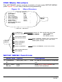
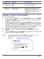
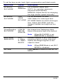
1
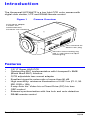
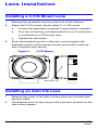
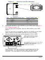
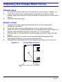
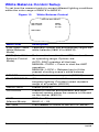
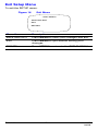
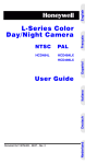
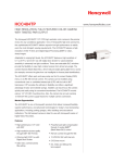
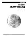
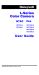
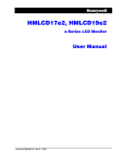
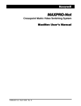
Color CCD Camera
NTSC
PAL
HCC484TP
HCC484TPX
User Guide
Document 900.0557 – 03/06 – Rev 1.00
Revisions
Issue
Date
Revisions
1.00
03/06
New document
Rev 1.00
ii
900.0557
03/06
Explanation of Graphical
Symbols
This symbol indicates the presence of
uninsulated “dangerous voltage” within
the product’s enclosure that may be of
sufficient magnitude to constitute a risk
of electric shock to persons.
This symbol indicates the presence of
important operating and maintenance
(servicing) instruction in the literature
accompanying the product.
CAUTION
RISK OF ELECTRIC
SHOCK DO NOT OPEN
CAUTION: TO REDUCE THE RISK OF
ELECTRIC SHOCK, DO NOT REMOVE THE
COVER (OR BACK). NO USER-SERVICEABLE
PARTS INSIDE. REFER SERVICING TO
QUALIFIED SERVICE PERSONNEL.
Rev 1.00
iii
900.0557
03/06
Warnings
Installation and servicing should be performed only by qualified and
experienced personnel.
For outdoor applications, use an appropriate protecting housing
conforming to IP65.
To prevent fire or shock hazard, do not
expose this camera to rain or moisture.
Safeguards
This camera is designed for use in general-purpose indoor CCTV
applications and no other purpose.
Only operate your camera between the temperature of -10°C to
+50°C (14°F to 122°F).
Do not operate your camera outside its specified power supply
range.
Camera must only be used in clean, dry, dust-free environments
unless housed in suitable protective housings to IP65 or better.
Rev 1.00
iv
900.0557
03/06
FCC Compliance Statement
Information to the User: This equipment has been tested and
found to comply with the limits for a Class A digital device. Pursuant
to Part 15 of the FCC Rules, these limits are designed to provide
reasonable protection against harmful interference when the
equipment is operated in a commercial environment. This
equipment generates, uses, and can radiate radio frequency energy
and, if not installed and used in accordance with the instruction
manual, may cause harmful interference to radio communications.
Operation of this equipment in a residential area is likely to cause
harmful interference in which case the user will be required to
correct the interference at his own expense.
Caution Changes or modifications not expressly approved by
the party responsible for compliance could void the
user’s authority to operate the equipment.
Manufacturer’s Declaration of
Conformance
The manufacturer declares that the equipment supplied with this
guide is compliant with the essential protection requirements of the
EMC directive 89/336/EEC and the Low Voltage Directive LVD 73/23
EEC, conforming to the requirements of standards EN 55022 for
emissions.
Rev 1.00
v
900.0557
03/06
Contents
Introduction . . . . . . . . . . . . . . . . . . . . . . . . . . . . . . . . . . . . . 1
Features . . . . . . . . . . . . . . . . . . . . . . . . . . . . . . . . . . . . . . 1
Before You Begin . . . . . . . . . . . . . . . . . . . . . . . . . . . . . . . 2
Unpack Everything . . . . . . . . . . . . . . . . . . . . . . . . . . . . . 2
Lens Installation . . . . . . . . . . . . . . . . . . . . . . . . . . . . . . . . . 3
Installing a C/CS Mount Lens . . . . . . . . . . . . . . . . . . . . . 3
Installing an Auto Iris Lens . . . . . . . . . . . . . . . . . . . . . . . . 3
Adjusting the Flange Back Focus. . . . . . . . . . . . . . . . . . 5
Fixed Lens . . . . . . . . . . . . . . . . . . . . . . . . . . . . . . . . . 5
Zoom Lens . . . . . . . . . . . . . . . . . . . . . . . . . . . . . . . . . 5
Mounting the Camera . . . . . . . . . . . . . . . . . . . . . . . . . . . 6
Connecting the Camera . . . . . . . . . . . . . . . . . . . . . . . . . 6
Programming . . . . . . . . . . . . . . . . . . . . . . . . . . . . . . . . . . . 8
Understanding the On-Screen Display . . . . . . . . . . . . . . 8
On-Screen Display . . . . . . . . . . . . . . . . . . . . . . . . . . . . . . 8
Saving your Settings . . . . . . . . . . . . . . . . . . . . . . . . . . . . 9
OSD Menu Structure . . . . . . . . . . . . . . . . . . . . . . . . 10
SETUP MENU Functions . . . . . . . . . . . . . . . . . . . . . 10
Adding a Camera Title Display . . . . . . . . . . . . . . . . 12
Setting the Camera Lighting Optimization . . . . . . . . . . 13
ELC / ALC Mode . . . . . . . . . . . . . . . . . . . . . . . . . . . . 13
White Balance Control Setup . . . . . . . . . . . . . . . . . . 15
Sync Control Setup . . . . . . . . . . . . . . . . . . . . . . . . . 16
Restore Factory Default Settings . . . . . . . . . . . . . . . 16
Exit Setup Menu . . . . . . . . . . . . . . . . . . . . . . . . . . . . 17
Specifications . . . . . . . . . . . . . . . . . . . . . . . . . . . . . . . . . . 18
Rev 1.00
vii
900.0557
03/06
Introduction
The Honeywell HCC484TP is a low light CCD color camera with
digital slow shutter, UTP and RS485 remote control.
Figure 1
Camera Overview
C/CS mount adapter:
C mount: turn
counterclockwise
CS mount: turn clockwise
Lens connector for
Auto Iris lens plug
Setscrew: loosen locking ring
with “L” type wrench to adjust
mounting ring.
Features
•
•
•
•
•
•
•
•
•
1/3” IT Super HAD CCD
Outstanding BLC implementation with Honeywell’s BMB
(Black Mask BLC) function
C/CS adjustable lens mount adapter
Excellent signal-to-noise ratio of more than 50 dB
High sensitivity: minimum illumination of 0.001 lux (F1.2, 30
IRE, DSS x 128)
2-way Auto Iris: Video Iris or Direct Drive (DC) Iris lens
OSD control
External synchronization with line lock and auto detection
RS485 remote control
Rev 1.00
1
900.0557
03/06
Before You Begin
Please read this guide carefully before
you install the HCC484TP camera.
Keep this guide for future reference.
Unpack Everything
Check that the items received match those listed on the order form
and packing slip. The HCC484TP packing box should include, in
addition to this User Guide:
•
One HCC484TP camera
•
One 4-pin connection cable
•
One L-type wrench
•
One Auto Iris lens plug
If any parts are missing or damaged, contact the dealer you
purchased the camera from or call Honeywell Customer Service
(see Contact Information on the back of this manual).
Rev 1.00
2
900.0557
03/06
Lens Installation
Installing a C/CS Mount Lens
1.
2.
3.
Remove the protective cap from the front of the camera.
Adjust the C/CS mount ring for either C or CS mount.
a.
Loosen the setscrews using the L-type wrench supplied.
b.
Turn the mount ring counterclockwise for a C-mount lens
or clockwise for a CS-mount lens.
c.
Tighten the setscrews.
Press the threaded portion of the lens mount against the
threaded portion of the camera mount and slowly screw the
lens clockwise until secure.
Figure 2
C
C/CS Mount
CS
Setscrews (x2)
Installing an Auto Iris Lens
1.
2.
Remove the cover of the auto iris lens plug and connect with
the lens cable.
Connect the auto iris lens plug to the 4-pin lens terminal on the
side of the camera.
Rev 1.00
3
900.0557
03/06
Figure 3
Auto Iris Lens Pin Definition
4-pin lens terminal
3.
2
1
4
3
Pin
DC (Direct Drive) lens
Video (VSD) lens
1
CTRL -
Power (+12V)
2
CTRL +
NC
3
DRV +
Video Signal
4
DRV -
GND
Set the EE MODE to ALC MODE on the OSD menu (see ELC /
ALC Mode on page 13).
Auto iris lens with amplifier: Set the VSD LENS on the OSD
menu.
Auto iris lens with no amplifier: Set the DC LENS on the OSD
menu. Adjust to the LEVEL carefully to avoid hunting.
4.
Set the switch on the rear of the camera to DC or VSD.
Video Output Selection Switch:
Set to CV for Composite Video.
Set to TP for UTP Video.
VIDEO
UP
CONT
MENU
-
+
DOWN
CV
Set to VSD for an auto iris lens with a builtin amplifier (video-type lens).
Set to DC for an auto iris lens without an
amplifier (DC-type lens).
VSD
DC
Auto iris lens: Use the connection recommended by the
manufacturer. For best practices, read the lens manual
carefully. You may need to set the flange back focus.
Rev 1.00
4
900.0557
03/06
Adjusting the Flange Back Focus
Fixed Lens
1.
2.
3.
Loosen the setscrew and set the lens focus ring to infinity (∞).
Turn the back focus adjustment ring until you see a clear
image (the distance from the camera to the object is more than
23 m).
Tighten the setscrew.
Zoom Lens
1.
2.
3.
4.
5.
6.
Loosen the setscrew and set the lens to the maximum
telephoto position.
Turn the back focus adjustment ring to adjust the focus.
Auto iris lens: Aim the camera at a comparatively dark object or
reduce the ambient light so that the iris is fully open.
Set the lens to its maximum wide angle position, then set the
focus.
Repeat steps 2, 3 and 4 until the difference between the
focusing positions is as small as possible.
Tighten the setscrew when the best focusing point is found.
Figure 4
Flange Back Focus
Back focus adjustment Setscrew
ring
Rev 1.00
5
900.0557
03/06
Mounting the Camera
Mounting points are provided on the top of the camera for mounting
the camera on a bracket or tripod. They are designed to accept
standard sized mounting bolts. This bracket can be unscrewed and
mounted onto the opposite side of the camera, depending on your
application. The mounting bracket must be capable of supporting
the weight of the camera and its lens.
Note
Some installation codes dictate that the mounting
bracket must be capable of supporting up to four
times the combined weight of the camera and lens.
Figure 5
Camera Mount
Unscrew 3 bracket
securing screws and
then resecure the
bracket on the other
side of the camera.
Connecting the Camera
Note
1.
2.
3.
Check the power source from the external power
supply before applying power to the camera.
Connect the VIDEO connector on the rear of the camera to the
video-in connector on your monitor.
Connect the camera to a 12 VDC or 24 VAC power supply
(appropriate for your installation).
Plug in the power supply. The power LED illuminates to show
that the camera is receiving power. If it does not illuminate,
check the connections and the power source.
WARNING!
Rev 1.00
The use of a CSA Certified/UL Listed
Class 2 power supply is required to
ensure compliance with electrical
safety standards.
6
900.0557
03/06
Figure 6
Camera Connections
Power LED
Monitor
VIDEO
UP
CONT
MENU
-
+
CV
DOWN
VSD
DC
Remote Control Connections
The HCC484TP can be controlled remotely using an RS485
connection.
Figure 7
Connect to
Serial Port
(COM1 or
COM2)
Serial
cable
Camera Connection via RS485
4P Cable
RS485
converter
VIDEO
UP
4-Pin Cable Legend
CONT
MENU
1. Red
2. Blue
3. Yellow
4. Black
-
Not used
TRxTRx+
Not used
+
DOWN
CV
VSD
DC
RS485 Converter
TRx+
TRx-
4P Cable
3
2
TRx+
TRx-
Remote Access Software Program On your PC (optional).
Connect with cable through the serial port on your PC to
simulate task buttons for configuration.
Rev 1.00
7
900.0557
03/06
Programming
Understanding the On-Screen Display
Press MENU briefly to confirm the current operation setup. The
information (see Figure 8) will disappear after a few seconds if there
is no button action.
Even though the OSD message disappears the Camera ID or Title
will continue to display. If you do not wish to display the ID, you can:
•
With external communication, change the display position.
Options are: Bottom right, Bottom left, Top left, Top right, Non
display.
Figure 8
OSD Information Display
CAM ID/TITLE
CAM ID/TITLE
Back
Light
Shutter
Speed
CAM ID/TITLE
Note
WB
Mode
CAM ID/TITLE
If you do not need to display the Operating OSD (for
example, for an external text overlay board), it can
be set to OFF at all times through a remote control
using RS485 connection.
On-Screen Display
Use the OSD (On-Screen Display) to program the camera.
1.
2.
3.
Press and hold the MENU (center) button for 2 seconds to
display the Setup menu.
Press the UP or DOWN buttons to select a menu item.
Press the MENU button to enter the selected submenu.
Rev 1.00
8
900.0557
03/06
4.
Press the + or – buttons to increase/decrease the value of the
selected item.
Figure 9
OSD Menu Controls
+
Saving your Settings
First Method: When you are satisfied with your settings:
1.
Press MENU for two seconds. The SETUP Menu is replaced
by one of two messages:
SAVE? displays when values have been changed. Selecting
SAVE exits Setup mode and saves your changes.
QUIT? displays when you have not changed any settings.
Selecting QUIT exits Setup mode without saving any changed
values.
2.
Press + or – to select SAVE or QUIT and press MENU to exit
the Setup mode. Press the UP or DOWN buttons to cancel the
SAVE/QUIT and return to the SETUP MENU.
Second Method: Select EXIT MENU on the SETUP MENU, press
MENU, and select SAVE AND EXIT to save the changed settings
and exit the menu. Select EXIT to exit without saving the settings.
Rev 1.00
9
900.0557
03/06
OSD Menu Structure
The HCC484TP menu system consists of one main SETUP MENU
(see Figure 10) for easy camera programming.
Figure 10
1
2
3
4
5
6
7
8
9
Menu Structure
<<SETUP MENU>>
CAMERA ID
002
ELC / ALC
ALC
SHUTTER
1/50
WB CONTROL
ATW
AGC CONTROL
34dB
DSS CONTROL
AUTO
MAX FIELD
x128
SYNC. CONT.
AUTO
RESTORE DEFAULT
EXIT MENU
…
…
…
SETUP
MENU
…
…
…
… indicates submenus
CAMERA ID
Camera ID, Title and Display Position
ELC/ALC MODE
ELC Mode:
ALC Mode:
SHUTTER SPEED
WHITE BALANCE
SETUP
MENU
AUTO, MANUAL
VSD LENS
DC LENS (Level)
ATW, Outdoor, Indoor, User, Fluorescent
AWC (Auto, Manual; Push and Lock)
MWB (RED, BLUE)
AGC CONTROL
DSS CONTROL
MAX FIELD
SYNC CONTROL
AUTO, INTERNAL, Line Lock (V.PH)
RESTORE DEFAULT
EXIT MENU
SETUP MENU Functions
Menu Item Option
1 CAMERA
ID
Description
000 (off), 001 … 255 ID set to 0 will turn ID display
off.
2 ELC / ALC ELC …
Mode
Rev 1.00
See ELC / ALC Mode for
more information.
ALC …
10
900.0557
03/06
Menu Item Option
3 SHUTTER
SPEED
Description
1/60 NTSC (1/50
PAL)
Adjust brightness with high
shutter speed.
Flicker
FL
This field is not adjustable
1/250, 1/500, 1/1000, when the camera is set to
ELC MODE. Auto is
1/2000, 1/4000,
selected by default.
1/10000, 1/30000,
1/50000
4 WB
White balance mode, auto
and manual.
ATW
CONTROL AWC
MWB
(White
Balance)
Preset white balance modes
include INDOOR,
FLUORESCENT, USER and
OUTDOOR.
5 AGC
OFF
CONTROL 10 dB
12 dB … 38 dB
Adjust maximum value of
AGC gain.
If the DSS CONTROL
(Sensitivity UP) Mode is set
to AUTO or FIX, you can
adjust the AGC from 18 dB
to 38 dB.
6 DSS
Compensate for low
illumination. Adjust the
maximum integration fields
to get a brighter dynamic
image. The scene will be
slower than when set to
OFF.
7 MAX FIELD OFF
The larger this field, the
greater the noise of the
image. For more dynamic
range, adjust the MAX FIELD
and increase the AGC
CONTROL setting.
OFF
CONTROL AUTO
FIX
CONTROL x2, x4, x6, x8, x10,
x16, x32, x64, x128
Rev 1.00
11
900.0557
03/06
Menu Item Option
Description
8 SYNC
See Sync Control Setup for
more information.
AUTO
CONTROL INT
L/L
9 RESTORE RESTORE DEFAULT Restore the factory default
DEFAULT
SETTINGS
settings. If you have not
made any changes, you will
not be able to select this
setting.
Adding a Camera Title Display
To add a camera title:
1.
2.
3.
4.
5.
6.
Enter the SETUP MENU, select CAMERA ID and press MENU.
Use the UP, DOWN, +, – buttons to select a character in the
TITLE to start editing with.
When the position is set, use the UP, DOWN, +, – buttons to
move between the alphanumeric characters. When the desired
character is blinking, press MENU to accept it. The character
appears in the title at the bottom of the screen. The cursor will
automatically highlight the next position in the TITLE.
Repeat step 2 until your camera title is complete.
Use the + and – buttons to change the DISPLAY field to
TITLE.
Select RETURN and press MENU to accept your changes and
return to the main SETUP MENU.
Note
For remote control using RS485 connection, you can
select either Camera ID or Title to display.
Figure 11
Adding Camera Title
CAM ID: 002
DISPLAY: TITLE
POSITION: T.R.
123456789ABCDEF
GHIJKLMNPQRSTUVW
XYZabcdefghijklm
nopqrstuvwxyz,.:
;~!?$%*&/<>+-=
TITLE: HCC484TP
RETURN
■■
Rev 1.00
12
■
900.0557
03/06
CAMERA ID Menu Functions
Menu Item
Option
Description
CAM ID
OFF, 001
… 255
The number assigned each camera in
your network, from 000 to 255. When set
to 000 the ID is not displayed on the
screen.
DISPLAY
TITLE, ID, Select what is displayed on the screen
OFF
(Camera TITLE, ID or nothing).
POSITION
T.R., B.R., Select where you want the Camera ID or
B.L., T.L., Title to appear on the display (Top Right,
NO DISP Bottom Right, Top Left, Bottom Left and
No Display).
TITLE
Enter a name for the camera, maximum
10 characters, including spaces.
RETURN
Press MENU to return to the main
SETUP MENU.
Setting the Camera Lighting Optimization
ELC / ALC Mode
Figure 12
Setting Camera Lighting
<ELC / ALC MODE>
EE MODE:
ALC MODE
DC LENS
LEVEL 06
OFF
OFF
BLC MODE:
BMB MODE:
RETURN
Rev 1.00
13
900.0557
03/06
To set the lens mode, back light compensation and black mask:
Menu Item
Option
Description
EE MODE:
AUTO
MANUAL
For a manual (fixed) lens:
ELC MODE
AUTO: Iris operates electronic
exposure automatically.
MANUAL: Adjust the iris by changing
the high shutter speed manually.
EE MODE:
ALC MODE
VSD
LENS
DC LENS
Backlight
Compensation
BLC MODE
OFF
LOW BL
MID. BL
HIGH BL
For an automatic iris lens:
VSD: Select for video-type lens.
DC LENS: Select for direct drive-type
lens. Adjust the LEVEL until the
image is neither too bright nor too
dark.
Prevents the object in the center of
the image from darkening when
there is excessive light from behind.
Note
Black Mask
BMB MODE
OFF
L. GRAY
D. GRAY
BLACK
Another function of BLC that masks
excessive light to a dark level and
makes the image brighter so the
object is clear.
Note
RETURN
Rev 1.00
When BLC MODE is set,
BMB MODE is disabled.
When BMB Mode is set, BLC
MODE is disabled.
Press MENU to return to the SETUP
MENU.
14
900.0557
03/06
White Balance Control Setup
To set how the camera tracks to accept different lighting conditions
within the color range of 2800°K to 8000°K:
Figure 13
White Balance Control
<WHITE BALANCE>
WB MODE:
WB CONT:
MWB
R=00
B=00
RETURN
Menu Item
Description
ATW (Auto Trace
White Balance
Mode)
Feedback system that automatically aligns the
white balance (2800°K to 8000°K).
AWC (Auto White
Balance Control
Mode)
Performs faster action than ATW mode without
an operating range. Options are:
INDOOR
General indoor scenes preset (3200°K).
FLUORESCENT
Office environments with fluorescent or
tungsten lighting. Provides lowest dynamic
range of all presets (4200°K).
AUTO: AWC operates all the time
MANUAL: PUSH = Press to start the AWC
operation
MANUAL: LOCK = Release key to fit the
present shooting scene’s white balance
USER FIXED
Preset (4700°K)
OUTDOOR
Preset for outside environments and highcontrast scenes where the camera is focused
on the darker (6300°K).
MWB
(Manual Mode)
RED: 0 – 20
BLUE: 0 – 20
RETURN
Press MENU to return to the SETUP MENU.
Rev 1.00
15
900.0557
03/06
Sync Control Setup
To synchronize the vertical interval sync pulse of your camera with
other equipment to reduce the effect of picture roll on the monitor.
Figure 14
Sync Control Setup
<SYNC. CONTROL>
SYNC MODE:
AUTO
INTERNAL
RETURN
Menu Item
Description
INTERNAL
When line lock is not required.
LINELOCK
Adjust the proper phase:
V.PH: 000 – 300 (factory default is 0)
RETURN
Press MENU to return to the SETUP MENU.
Restore Factory Default Settings
To reload the factory default settings on the camera.
Figure 15
Restoring Default Settings
<RESTORE DEFAULT>
RESTORE FACTORY SETTING
RETURN
Menu Item
Description
RESTORE
Press MENU to Reload the factory default camera
settings.
This action replaces all user-defined settings.
RETURN
Rev 1.00
Press MENU to return to the SETUP MENU.
16
900.0557
03/06
Exit Setup Menu
To exit the SETUP menu.
Figure 16
Exit Menu
<EXIT MENU>
SAVE AND EXIT
EXIT
RETURN
Menu Item
Description
SAVE AND EXIT
Press MENU to save your changes and exit.
EXIT
Press MENU to quit without saving your
changes.
RETURN
Press MENU to return to the SETUP MENU.
Rev 1.00
17
900.0557
03/06
Specifications
Camera
HCC484TP (NTSC)
HCC484TPX (PAL)
Imaging device:
1/3” CCD (total
410,000 pixels)
1/3” CCD (total
470,000 pixels)
Effective pixel:
768 (H) x 494 (V)
(380,000 pixels)
752 (H) x 582 (V)
(440,000 pixels)
Scanning system: 525 lines, 2:1
interlace
625 lines, 2:1
interlace
Sync system:
Internal, Linelock,
Auto
Internal, Linelock,
Auto
Scanning
frequency:
15.734 KHz (H)
59.94 Hz (V)
15.625 KHz (H)
50.0 Hz (V)
Resolution:
480 TV Lines
Video out:
VBS 1.0 Vp-p / BNC
S/N ratio:
Minimum
illumination:
more than 50 dB
less than 0.1 lux (F1.2, 30 IRE, AGC ON)
DSS ON 0.001 lux (x128 fields)
BLC:
BMB:
White balance:
OFF, Low, Middle, High
OFF, Light Gray, Dark Gray, Black
1/60s ~ 1/50,000s
(10 steps)
1/50s ~ 1/50,000s
(10 steps)
AGC:
OFF ~ 38 dB
ALC:
EE, VSD, DC
Lens mount:
C/CS mount
Power source:
24 VAC ± 20%, 12 VDC ± 2V, Max 3W
Operating
temperature:
14°F ~ 122°F (-10°C ~ +50°C)
Storage
temperature:
-4°F ~ 158°F (-20°C ~ +70°C)
Enclosure
Dimension:
(W x H x D)
2.7 in. x 2.2 in. x 4.7 in.
(68 mm x 56 mm x 120 mm)
Weight:
Rev 1.00
13 oz. (380 g)
18
900.0557
03/06
Honeywell Video Systems (Head office)
2700 Blankenbaker Pkwy, Suite 150
Louisville, KY 40299, USA
www.honeywellvideo.com
℡ +1.800.796.2288
Honeywell Security Australia Pty Ltd.
Unit 5, Riverside Centre
24-28 River Road West
Parramatta, NSW 2150, Australia
www.ademco.com.au
℡ +61.2.8837.9300
Honeywell Security Asia Pacific
33/F Tower A, City Center, 100 Zun Yi
Road
Shanghai 200051, China
www.security.honeywell.com/cn
℡ +86 21.2527.4568
Honeywell Video Systems
Northern Europe
Netwerk 121
1446 WV Purmerend, The Netherlands
www.SecurityHouse.nl
℡ +31.299.410.200
Honeywell Video Systems UK Ltd.
Aston Fields Road, Whitehouse Ind Est
Runcorn, Cheshire, WA7 3DL, UK
www.honeywellvideo.com
℡ +0844 8000 235
Honeywell Security South Africa
Unit 6 Galaxy Park, 17 Galaxy Avenue
Linbro Park, P.O. Box 59904
2100 Kengray, Johannesburg
South Africa
www.honeywell.co.za
℡ +27.11.574.2500
Honeywell Security Asia
Flat A, 16/F, CDW Building
388 Castle Peak Road
Tsuen Wan, N.T., Hong Kong
www.security.honeywell.com/hk
℡ +852.2405.2323
Honeywell Security Germany
Großenbaumer Weg 8
40472 Düsseldorf, Germany
www.honeywell-security.de
℡ +49.211.41.50.90
Honeywell Security France
Parc Gutenberg, 8, Voie La Cardon
91120, Palaiseau, France
www.honeywell.com/security/fr
℡ +33.01.64.53.80.40
Honeywell Security Poland
Chmielewskiego 22a, 70-028
Szczecin, Polska
www.ultrak.pl
℡ +48.91.485.40.60
Honeywell Security Italia SpA
Via Treviso 2 / 4
31020 San Vendemiano
Treviso, Italy
www.honeywell.com/security/it
℡ +39.04.38.36.51
Honeywell Security Czech Republic
Havránkova 33, Brno
Dolní Heršpice, 619 00
Czech Republic
www.olympo.cz
℡ +420.543.558.111
Honeywell Security España
Calle Vivero, 5, 28040
Madrid, Spain
www.honeywell.com/security/es
℡ +34.91.102.5900
Honeywell Security Slovakia Republic
Vajnorská 142, 83104 Bratislava
Slovakia
www.olympo.sk
℡ +421.2.444.54.660
Video Systems
www.honeywellvideo.com
+1.800.796.CCTV (North America only)
Document 900.0557 03/06 Rev 1.00
© 2006 Honeywell International Inc. All rights reserved. No part of this publication
may be reproduced by any means without written permission from Honeywell Video
Systems. The information in this publication is believed to be accurate in all respects.
However, Honeywell Video Systems cannot assume responsibility for any
consequences resulting from the use thereof. The information contained herein is
subject to change without notice. Revisions or new editions to this publication may
be issued to incorporate such changes.
P/N: G-112656-001