1
SuperTAPP n+
Voltage Control Relay
User Manual
SuperTAPP n+ Voltage Control Relay
Contents
1
Introduction.......................................................................................................... 4
2
Key Features ....................................................................................................... 5
3
Quick SuperTAPP n+ Guide ................................................................................ 7
4
Relay Operation .................................................................................................. 9
4.1
4.2
4.3
4.4
4.5
Introduction ............................................................................................................. 9
Basic Principle......................................................................................................... 9
Real and Reactive Components .............................................................................. 9
Levels of Control ................................................................................................... 10
Modes of Operation ............................................................................................... 10
4.5.1
Auto Mode ........................................................................................................... 11
4.5.2
Non-Auto Mode ................................................................................................... 14
4.6
Peer-to-Peer Communications .............................................................................. 14
4.6.1
Introduction ......................................................................................................... 14
4.6.2
Group Load ......................................................................................................... 14
4.6.3
Topology Changes ............................................................................................... 15
5
Operational States ............................................................................................. 16
6
Failure States .................................................................................................... 23
6.1
6.2
7
Hardware Errors .................................................................................................... 23
CAN Bus Errors..................................................................................................... 23
Alarms ............................................................................................................... 25
7.1
7.2
8
Relay Healthy ........................................................................................................ 25
AVC Alarm ............................................................................................................ 25
Application ......................................................................................................... 26
8.1
8.2
8.3
8.4
8.5
9
Introduction ........................................................................................................... 26
Basic voltage target - Vbasic .................................................................................... 26
Voltage Adjustments - Vadj ..................................................................................... 26
Circulating Current - Vcirc ....................................................................................... 27
LDC - VLDC ............................................................................................................. 29
Application - Advanced Model Only ................................................................... 31
9.1
9.2
Introduction ........................................................................................................... 31
Multiple Analogue Inputs ....................................................................................... 31
9.2.1
Feeder Current Measurements ............................................................................ 31
9.2.2
Double-Secondary Winding Transformers ........................................................... 42
9.3
10
Advanced LDC ...................................................................................................... 43
Specification ................................................................................................ 45
10.1
10.2
v2.1
Hardware ........................................................................................................... 45
Relay Connections............................................................................................. 49
10.2.1
Power Supply ...................................................................................................... 50
10.2.2
Current Measurement Inputs ............................................................................... 51
10.2.3
Interposer CT ...................................................................................................... 52
Page 2 of 109
SuperTAPP n+ Voltage Control Relay
10.2.4
Tap Changer Outputs .......................................................................................... 55
10.2.5
Status Outputs ..................................................................................................... 56
10.2.6
Voltage Measurement Inputs ............................................................................... 57
10.2.7
Status Inputs ....................................................................................................... 58
10.2.8
CAN Bus Communications ................................................................................... 60
10.3
10.4
11
Accuracy ............................................................................................................ 62
Type Tests ......................................................................................................... 63
HMI .............................................................................................................. 64
11.1
11.2
11.3
Relay Fascia ...................................................................................................... 64
Display Messages.............................................................................................. 65
Menu System..................................................................................................... 65
11.3.1
Instruments .......................................................................................................... 66
11.3.2
Settings ............................................................................................................... 70
11.3.3
Faults .................................................................................................................. 74
12
Installation ................................................................................................... 76
12.1
12.2
12.3
13
Unpacking and Storage ..................................................................................... 76
Recommended Mounting ................................................................................... 76
SUPERTAPP n+ SYSTEM ................................................................................ 77
Commissioning ............................................................................................ 78
13.1
13.2
13.3
13.4
Introduction ........................................................................................................ 78
General Installation ............................................................................................ 78
Relay Settings ................................................................................................... 78
Relay Connections............................................................................................. 81
13.4.1
Analogue Inputs................................................................................................... 81
13.4.2
Digital Inputs ....................................................................................................... 84
13.4.3
Outputs ................................................................................................................ 86
13.4.4
CAN Bus .............................................................................................................. 87
13.5
Levels of Control ................................................................................................ 88
13.5.1
Local Control ....................................................................................................... 88
13.5.2
Remote Control ................................................................................................... 88
13.6
Modes of Operation ........................................................................................... 88
13.6.1
Non-Auto ............................................................................................................. 88
13.6.2
Auto ..................................................................................................................... 89
Appendix A
Appendix B
Appendix C
Appendix D
v2.1
- SuperTAPP n+ Scheme Drawings .................................................... 93
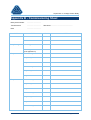
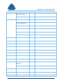
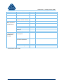
- Commissioning Sheet ....................................................................... 94
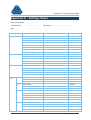
- Settings Sheet ................................................................................... 97
- Type Test Results ............................................................................. 99
Page 3 of 109
SuperTAPP n+ Voltage Control Relay
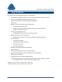
1
Introduction
The SuperTAPP n+ voltage control relay is used to regulate voltage on power transformers equipped
with an on load tap changer (OLTC). Voltage regulation on electrical networks must take account of
the increasing amount of embedded generation which is being connected. The SuperTAPP n+ relay is
designed to offer functionality to address this along with ‘standard’ requirements.
This user manual describes the design, functionality, operation and implementation of the SuperTAPP
n+ voltage control relay.
It is important to note that the SuperTAPP n+ relay is normally accompanied by the RTMU monitor
and control relay (Fundamentals product) to form a complete AVC (automatic voltage control) system.
Details of the RTMU relay can be found in a separate user manual.
v2.1
Page 4 of 109
SuperTAPP n+ Voltage Control Relay
2
Key Features
The main functions offered by SuperTAPP n+ are as follows:
•
Comprehensive voltage regulation for power transformers with on-load tap-changers
•
Functions for embedded generation and reverse power
•
Easily configurable for full range of application complexity
•
Future proof
•
Multiple CT and VT inputs with flexible rating range
•
•
Customisable analogue inputs
•
Voltage averaging and load summation for double winding transformers
•
Feeder current measurements
Load drop compensation (LDC)
•
•
Parallel operation of up to 6 transformers
•
•
Load exclusion and correction for troublesome loads
Enhanced TAPP principle (Transformer Automatic Paralleling Package)
OLTC Monitoring:
•
Tap position indication*
•
Tap changer runaway prevention*
•
Tap changer blocking*
•
Fuse-failure detection*
•
SCADA Communications (DNP3, IEC61850)†
•
Web monitoring
•
User friendly HMI with push button and digital display
•
Integral instrumentation to display measurements and calculations
•
Digital inputs and outputs
•
Voltage adjustments for load shedding/boosting
•
Continuous self-supervision of hardware and software for enhanced system reliability
†
•
Auto-diagnostic fault indication to facilitate troubleshooting
* available only when used in conjunction with an RTMU relay
† available only when used in conjunction with an ENVOY unit
v2.1
Page 5 of 109
SuperTAPP n+ Voltage Control Relay
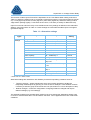
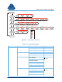
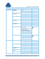
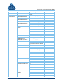
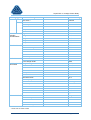
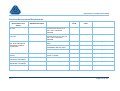
The SuperTAPP n+ voltage control relay is available as a ‘basic’ model or as an ‘advanced’ model.
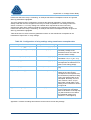
Table 1 shows the differences between the two models.
Table 1 – Differences between basic and advanced models
Feature
Basic
Advanced
# activated VT inputs
1
2
# activated CT inputs
1
3
Load Drop Compensation
Transformer Paralleling
Voltage Reduction
Embedded Generation Functions
Load Exclusion
Load Inclusion
Load Correction
Averaging for double-secondary windings
VT Switching
The basic model is easily upgraded to an advanced model without hardware or software modifications
to the relay. In order to perform an upgrade, the user simply programs a ‘key code’ (purchased from
Fundamentals Ltd) into the relay settings.
v2.1
Page 6 of 109
SuperTAPP n+ Voltage Control Relay
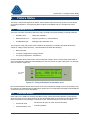
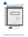
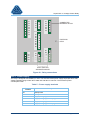
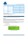
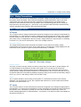
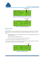
3
Quick SuperTAPP n+ Guide
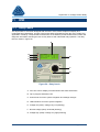
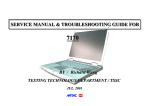
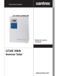
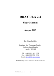
This section provides a brief description of the relay indications and available information to help
users quickly identify the operational state of the relay. More detailed descriptions are presented in
later sections.
A
HIGH
G
F
E
VOLTAGES
Basic targt 11.00 kV
Calc target 11.00 kV
Measured
0.00 kV
B
TAP
LOW
SuperTAPP n+
PRESS
VOLTAGE
CONTROL
RELAY
TURN
C
INSTRUMENTS
D
SETTINGS
FAULTS
Model
Ser.No.
Fundamentals Ltd
www.fundamentals.co.uk
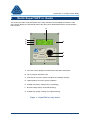
A. Four line LCD for display of measurement and status information
B. Tap in progress indication LED
C. Control knob for menu system navigation and settings changes
D. LED indications for menu system navigation
E. Voltage low (solid) / Voltage very low (flashing)
F. Normal voltage (solid) / Overload (flashing)
G. Voltage high (solid) / Voltage very high (Flashing)
Figure 1 – SuperTAPP n+ relay fascia
v2.1
Page 7 of 109
SuperTAPP n+ Voltage Control Relay
A
G
F
B
C
D
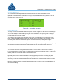
V 11.00 kV LOC AUTO*
Load
590A +0.96 Lg
Group 1180A +0.96 Lg
Lo>-------ஊ------<Hi
E
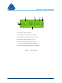
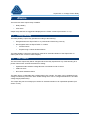
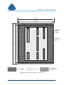
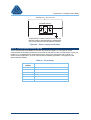
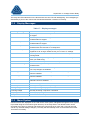
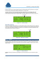
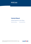
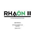
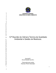
A. Measured voltage indication
B. Control level indication: Local / Remote
C. Operation mode indication: Auto/ Non-auto
D. Alternative settings indication: = on
E. Bar chart indication of voltage level OR
Time to tap indication OR Error message
F. Group load measurement OR Error message
Figure 2 – LCD display
v2.1
Page 8 of 109
SuperTAPP n+ Voltage Control Relay
4
Relay Operation
4.1
Introduction
The SuperTAPP n+ relay has 2 VT inputs and 3 CT inputs available for use. The basic model has one
VT and one CT activated. The advanced model has all inputs activated for use. The description of
operation presented in the following sections is valid for basic and advanced models.
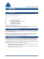
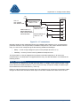
4.2
Basic Principle
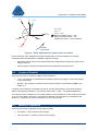
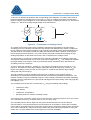
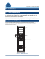
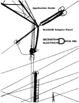
Basic relay operation can be described with reference to Figure 3 which shows a single tap changing
transformer supplying a busbar with two outgoing feeders. Normally, the tap changer is on the high
voltage side of the transformer and the VT and CT are on the low voltage side.
n+
ITL
VVT
I1
I2
Figure 3 – Simplified AVC application
The voltage control relay measures the voltage (VVT) and the current (ITL). The measured voltage is
used for regulation, but also as a reference to calculate the real and reactive components of the
current.
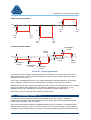
4.3
Real and Reactive Components
The real and reactive components of measured current are useful for display purposes but are also
very important for various relay calculations (as described throughout this manual). The relay uses the
measured voltage as a reference to calculate the relative phase of the measured current.
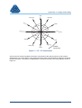
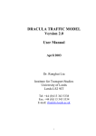
For correct calculation of real and reactive components, the phases of VT and CT inputs must be
configured correctly in the settings (see section 11.3.2). The relay uses the phase configurations to
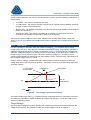
make the appropriate adjustments to measured angles between the voltage and current. Figure 4
shows how the relay works in this respect.
v2.1
Page 9 of 109
SuperTAPP n+ Voltage Control Relay
VCA
IC
Imeas
20°
150°
IB
VAB
IA
VBC
VT = B-C
CT = C
Imeas = -170°
RELAY CORRECTION = +150°
REAL SYSTEM PHASE = -20°
POWER FACTOR = +0.94 LAGGING
PHASE
ROTATION
Figure 4 – Relay adjustment for power factor calculation
Correct selection of the voltage/current phase relationship is critical for operation of the relay.
Comprehensive instrumentation is available to aid this including:
•
Secondary values of all current measurements with magnitude and angle with respect to the
voltage reference
•
Primary values of all current measurements with magnitude and power factor
4.4
Levels of Control
There are two levels of control for voltage control as follows:
•
Local – tap changer is controlled at the substation (at the tap changer or at the tap changer
control panel/relay)
•
Remote – tap changer is controlled via the relay by SCADA communications (DNP3, IEC
61850 etc.)*
* SCADA communications is available only with an accompanying ENVOY unit (communications
platform developed specifically for use with the SuperTAPP n+ relay – see separate datasheet)
The relay has inputs available to use to switch between Local and Remote control modes (see section
10.2.7 for more detail). These are only used where SCADA communications is used (DNP3, IEC
61850 etc.), otherwise the relay is permanently in Local control mode.
4.5
Modes of Operation
There are two modes of operation for the relay as follows:
•
Auto Mode – relay controls the tap changer
•
Non-Auto Mode – operator controls the tap changer
v2.1
Page 10 of 109
SuperTAPP n+ Voltage Control Relay
These modes of operation can exist in Local and Remote control to give the following combinations of
control mode:
•
Local Auto – tap changer controlled by the relay
•
Local Non-Auto – tap changer manually controlled by an operator at the substation (at the tap
changer or at the control panel/relay)
•
Remote Auto – tap changer controlled by the relay but influenced by SCADA communications
(DNP3, IEC 61850 etc.)
•
Remote Non-Auto – tap changer controlled via an operator by remote raise and lower
commands over SCADA communications (DNP3, IEC 61850 etc.)
The relay has inputs available to use to switch between Auto and Non-Auto control modes (see
section 10.2.7 for more detail). Auto and Non-Auto modes of operation are considered in the following
sections.
4.5.1
Auto Mode
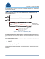
For relay operation in automatic mode, the measured voltage (VVT) is compared with the target
voltage of the relay (Vtgt). If the difference exceeds the bandwidth setting, a tap changer operation is
initiated to adjust the transformer voltage to a satisfactory level. To avoid tap changer operations for
short term voltage fluctuations, it is normal practice for a time delay to take place prior to initiation of
the tap change. This is shown in Figure 5 where the measured voltage (VVT) increases until it is
outside of the dead-band, at which point the VCR initiates a ‘lower’ command* after a time delay and
the measured voltage returns to normal.
*lower in terms of voltage, not necessarily tap position number (some tap changers increase the
voltage when they move to a lower tap position – see section 10.2.4 for more information about raise
and lower outputs).
VVT EXCEEDS
UPPER LIMIT
TIME DELAY
TAP DOWN
VVT
Vtgt
RELAY
BANDWIDTH
TIME
Figure 5 – Tap changer operation time delay
The target voltage of the relay (Vtgt) comprises several components which are calculated in real time
according to the prevailing network conditions as measured by the relay. This is discussed in more
detail in the following section.
Target Voltage
The relay target voltage is a dynamic quantity and is affected by several factors associated with the
voltage control system. The calculation of the relay target voltage is shown in Equation 1:
v2.1
Page 11 of 109
SuperTAPP n+ Voltage Control Relay
Vtgt = Vbasic + Vadj + Vcirc + V LDC + V gen
(1)
where
Vtgt
Vbasic
Vadj
Vcirc
VLDC
Vgen
=
=
=
=
=
=
relay target voltage used for control
relay basic target voltage setting
voltage target adjustments applied via status inputs
circulating current bias voltage
load drop compensation bias voltage
embedded generator bias voltage*
* available only with an advanced model
These quantities are all expressed in % values where 100% voltage is the nominal voltage of the
network which the transformer is supplying. Each quantity is considered in the Applications section 8.
Bandwidth
The bandwidth setting of the relay defines the sensitivity to voltage fluctuations. Reducing the
bandwidth setting will maintain the voltage closer to the target level (i.e. increase the voltage control
accuracy), but will increase the number of tap changer operations. It is normally represented by a ±%
value based on the system nominal voltage.
The bandwidth setting is determined by the voltage step of the tap changer. To optimise the number
of tap changer operations it should be set to one tap step (as shown in Figure 5). Care should be
taken not to set the bandwidth lower than half a tap step since this will result in ‘hunting’, where one
tap operation can cause the voltage to move across the bandwidth and result in a call for another tap
operation in the opposite direction (see Figure 6).
TAP DOWN
OPERATIONS
VVT
RELAY
BANDWIDTH
Vtgt
TIME
TAP UP
OPERATIONS
Figure 6 – Tap changer ‘hunting’
Time Delays
When the need for a voltage adjustment is sensed, an initial time delay takes place before the relay
issues the raise/lower command. This initial time delay is included to ensure that unnecessary
operations do not occur for transient voltage deviations.
The delay is presented on the relay screen as ‘time to tap’, which counts down from the setting to
zero, at which point a tap changer operation is initiated. If during the timing cycle the voltage returns
v2.1
Page 12 of 109
SuperTAPP n+ Voltage Control Relay
to normal, the time delay count will increase at the same rate back to the initial time delay setting (but
not displayed on the screen).Where further corrections are required following an initial time delay and
tap changer operation, an inter-tap time delay is used. If during the inter-tap timing cycle the voltage
returns to normal, the inter-tap time count will be reset and the initial time delay count will increment
from zero towards the initial time setting. The effect of these timers is shown in Figure 7.
TAP DOWN
INTER-TAP
TIMER
TAP DOWN
t < INITIAL TAP
TIMER
INITIAL TAP
TIMER
VVT
RELAY
BANDWIDTH
Vtgt
TIME
Figure 7 – Multiple tap changer operations
The inter-tap time should be set to longer than the operation time of the tap changer (for safety at
least 25% longer than the tap changer operation time). This is to avoid attempted raise/lower
operations while the tap changer is in operation (which can cause a lockout if an RTMU relay is being
used).
The initial time delay for the first period is adjustable from 10 seconds to 120 seconds. The inter-tap
delay operative for all successive time delays is adjustable from 5 seconds to 120 seconds.
If the voltage cannot be corrected (e.g. tap changer mechanism fault or end of range), the relay will
stop issuing raise/lower signals when the associated AVC alarm has been raised (dependent on the
relay alarm time setting).
Fast Tap
Under some circumstances the initial time delay can be over-ridden and a corrective tap changer
operation can be initiated after a short, fixed time delay of 4 seconds. The conditions under which fast
tapping can take place are as follows:
•
High voltage 2% above band*
•
Low voltage 2% below band*
•
Detection of a measuring voltage > 80% of nominal after a previous zero voltage (<25%)
•
Switching to ‘Auto’ when the relay has been in ‘Non-Auto’ for a period of more than the ‘initial
time delay’
•
At power on **
•
Following a change to the relay basic voltage target (-3%, -6% etc.).
•
When preparing for switch-out
v2.1
Page 13 of 109
SuperTAPP n+ Voltage Control Relay
* this must be configured in the relay settings where the user can specify under which voltage conditions a fast
tap takes place
** subject to internal checks relating to measurement and communications data
4.5.2
Non-Auto Mode
In this mode the relay maintains measurements and indications according to the operational state
(see section 5) but does not issue tap changer operations or operational alarms. Normally this would
represent situations where the tap changer is operated by an operator, which could be at one of the
following locations:
•
Relay control panel (panel push buttons or accompanying RTMU relay switches*)
•
At the tap changer
•
Remote control (SCADA communications)
*see separate user manual for information relating to the RTMU relay
4.6
Peer-to-Peer Communications
4.6.1
Introduction
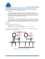
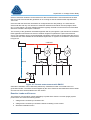
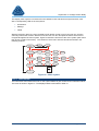
It is common to operate multiple power transformers in parallel for security of supply. SuperTAPP n+
can accommodate parallel operation of up to six units using the peer-to-peer communications bus
system (CAN bus). Units operating together on the CAN bus should have the same software version
to ensure compatibility.
In order to aid understanding of relay operation, some terminology is introduced by reference to
Figure 8 which shows multiple SuperTAPP n+ relays as a typical voltage control scheme with peer-topeer communications. Implementation details of the CAN bus is described in section 10.2.8.
CAN BUS COMMUNICATIONS
T1
T2
n+ 1
n+ 2
ITL-2
ITL-1
VVT-2
VVT-1
X
CB 1
Figure 8 – Peer-to-peer communications on CAN bus
4.6.2
Group Load
Each relay on the CAN bus reports measurement and status information which is received by all
relays on the bus. Each relay has a transformer ID and a group ID which are configured in the
settings. Relays in the same group will use measurement data to calculate the group load as follows:
v2.1
Page 14 of 109
SuperTAPP n+ Voltage Control Relay
Igroup = ITL-1 + ITL-2 + ….ITL-n
where transformers 1 to n are in the same group*
The group load is important for operational calculations (see the Applications section 8.) and is
displayed with the individual transformer measured current on the default screen of the relay.
Each unit on the CAN bus should have a unique transformer ID, otherwise there will be
communication errors which could result in load summation inaccuracy.
*there are some situations (e.g. embedded generation) where this equation calculation does not hold – see
Advanced Applications section 9.
4.6.3
Topology Changes
In order that CAN bus information is used correctly, the grouping must accurately represent which
relays are operating in parallel. Table 2 shows an example of how the grouping should change
according to the status of the bus-section circuit breaker shown in Figure 8.
Table 2 – Group load according to bus section status
CB Status
T1
T2
Closed
Open
Transformer ID
1
1
Group ID
1
1
Group Load
ITL2 + ITL2
ITL1
Transformer ID
2
2
Group ID
1
2
Group Load
ITL2 + ITL2
ITL2
It is possible to change the group ID (and other settings as appropriate) by use of a subset of the
settings which can be adopted when the dedicated ‘alternative settings’ status input is activated.
Normal settings will be used when the input is de-activated/de-energised.
This can be implemented automatically by use of an auxiliary contact on the circuit breaker, or
manually from the control room. The ‘alternative settings’ is described in more detail in section 10.2.7
(digital status inputs).
v2.1
Page 15 of 109
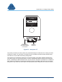
SuperTAPP n+ Voltage Control Relay
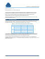
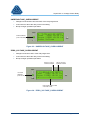
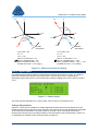
5
Operational States
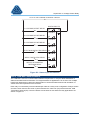
Figure 9 shows the various operational states that will be generated with the associated voltage and
loading conditions. Each state is described in a corresponding section with example screen shots to
show relay indications.
VOLTAGE
UPPER BAND
+2%
UPPER BAND
Vtgt
VOLTAGE_VERY_HIGH
VOLTAGE_VERY_HIGH_OVERCURRENT
VOLTAGE_HIGH
VOLTAGE_HIGH_OVERCURRENT
VOLTAGE_NORMAL
OVERCURRENT
VOLTAGE_LOW
VOLTAGE_LOW_OVERCURRENT
VOLTAGE_VERY_LOW
VOLTAGE_VERY_LOW_OVERCURRENT
UNDERVOLTAGE
UNDERVOLTAGE_OVERCURRENT
ZERO_VOLTAGE
ZERO_VOLTAGE_OVERCURRENT
LOWER BAND
LOWER BAND
-2%
80% Vtgt
25% Vtgt
LOAD
CURRENT
OVERCURRENT
LEVEL
Figure 9 – Operational states
v2.1
Page 16 of 109
SuperTAPP n+ Voltage Control Relay
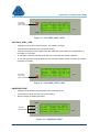
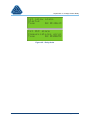
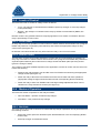
VOLTAGE_NORMAL
•
Voltage is within the deadband.
•
Load current is below the relay overcurrent setting.
•
Raise/lower operations permitted.
RELAY IN LOCAL
CONTROL MODE
RELAY IN AUTO
CONTROL MODE
HIGH
V 11.00 kV LOC AUTO
Load
590A +0.96 Lg
Group 1180A +0.96 Lg
Lo>-------ஊ------<Hi
VOLTAGE
NORMAL
(LED SOLID)
TAP
LOW
BAR CHART INDICATING
VOLTAGE LEVEL
Figure 10 – VOLTAGE_NORMAL
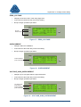
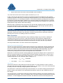
VOLTAGE_HIGH
•
Voltage is up to 2% higher than the upper band level.
•
Load current is below the relay overcurrent setting.
•
In automatic mode the relay will count down to a corrective tap changer operation.
•
In non-auto mode the relay will display an out-of-band condition but will not issue tap changer
operation commands.
VOLTAGE
HIGH
(LED SOLID)
HIGH
V 11.10 kV LOC AUTO
Load
590A +0.96 Lg
Group 1180A +0.96 Lg
Time to top 15s
TAP
LOW
TIME TO
TAP OPERATION
Figure 11 – VOLTAGE_HIGH (automatic mode)
v2.1
Page 17 of 109
SuperTAPP n+ Voltage Control Relay
RELAY IN NON-AUTO
CONTROL MODE
HIGH
VOLTAGE
HIGH
(LED SOLID)
V 11.10 kV LOC N/A
Load
590A +0.96 Lg
Group 1180A +0.96 Lg
Voltage out of band
TAP
LOW
Figure 12 – VOLTAGE_HIGH (non-automatic mode)
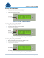
VOLTAGE_LOW
•
Voltage is up to 2% lower than the lower band level.
•
Load current is below the relay overcurrent setting.
•
In automatic mode the relay will count down to a corrective tap changer operation.
•
In non-auto mode the relay will display an out-of-band condition but will not issue tap changer
operation commands.
HIGH
VOLTAGE
LOW
(LED SOLID)
V 10.90 kV LOC AUTO
Load
590A +0.96 Lg
Group 1180A +0.96 Lg
Time to tap 15s
TAP
LOW
Figure 13 – VOLTAGE_LOW
VOLTAGE_VERY_HIGH
•
Voltage exceeds the upper band + 2%.
•
Load current is below the relay overcurrent setting.
•
Fast tap operations can be configured for this state where the initial timer is bypassed for a
time delay of 4 seconds.
•
In automatic mode the relay will count down to a corrective tap changer operation.
•
In non-auto mode the relay will display an out-of-band condition but will not issue tap changer
operation commands.
v2.1
Page 18 of 109
SuperTAPP n+ Voltage Control Relay
VOLTAGE
VERY HIGH
(LED FLASHING)
HIGH
V 11.50 kV LOC AUTO
Load
590A +0.96 Lg
Group 1180A +0.96 Lg
Time to tap 15s
TAP
LOW
Figure 14 – VOLTAGE_VERY_HIGH
VOLTAGE_VERY_LOW
•
Voltage level is between the lower band - 2% and 80% of target.
•
Load current is below the relay overcurrent setting.
•
Fast tap operations can be configured for this state where the initial timer is bypassed for a
time delay of 4 seconds.
•
In automatic mode the relay will count down to a corrective tap changer operation.
•
In non-auto mode the relay will display an out-of-band condition but will not issue tap changer
operation commands.
HIGH
VOLTAGE
VERY LOW
(LED FLASHING)
V 10.70 kV LOC AUTO
Load
590A +0.96 Lg
Group 1180A +0.96 Lg
Time to tap 15s
TAP
LOW
LOW
Figure 15 – VOLTAGE_VERY_LOW
UNDERVOLTAGE
•
Voltage level is between 80% and 25% of the relay target level.
•
Load current is below the relay overcurrent setting.
•
No tap changer operations permitted.
HIGH
V 7.70 kV LOC AUTO
Load
590A +0.96 Lg
Group 1180A +0.96 Lg
Under Voltage
NO LED
INDICATIONS
TAP
LOW
LOW
Figure 16 – UNDERVOLTAGE
v2.1
Page 19 of 109
SuperTAPP n+ Voltage Control Relay
ZERO_VOLTAGE
•
Voltage level is below 25% of the relay target level.
•
Load current is below the relay overcurrent setting.
•
No tap changer operations permitted.
HIGH
V 0.00 kV LOC AUTO
Load
0A +0.96 Lg
Group 1180A +0.96 Lg
Zero Voltage
NO LED
INDICATIONS
TAP
LOW
LOW
Figure 17 – ZERO_VOLTAGE
OVERCURRENT
•
Voltage is within the deadband.
•
Load current is above the relay overcurrent setting.
•
No tap changer operations permitted.
HIGH
V 11.00 kV LOC AUTO
Load 1900A +0.96 Lg
Group 2490A +0.96 Lg
Overcurrent
OVERCURRENT
(LED FLASHING)
TAP
LOW
Figure 18 – OVERCURRENT
VOLTAGE_HIGH_OVERCURRENT
•
Voltage is up to 2% higher than the upper band level.
•
Load current is above the relay overcurrent setting.
•
No tap changer operations permitted.
VOLTAGE HIGH
(LED SOLID)
OVERCURRENT
(LED FLASHING)
HIGH
V 11.10 kV LOC AUTO
Load 1900A +0.96 Lg
Group 2490A +0.96 Lg
Overcurrent
TAP
LOW
Figure 19 – VOLTAGE_HIGH_OVERCURRENT
v2.1
Page 20 of 109
SuperTAPP n+ Voltage Control Relay
VOLTAGE_LOW_OVERCURRENT
•
Voltage is up to 2% lower than the lower band level.
•
Load current is above the relay overcurrent setting.
•
No tap changer operations permitted.
HIGH
V 10.90 kV LOC AUTO
Load 1900A +0.96 Lg
Group 2490A +0.96 Lg
Overcurrent
OVERCURRENT
(LED FLASHING)
TAP
LOW
LOW
Figure 20 – VOLTAGE_LOW_OVERCURRENT
VOLTAGE_VERY_HIGH_OVERCURRENT
•
Voltage exceeds the upper band + 2%.
•
Load current is above the relay overcurrent setting.
•
No tap operations are permitted.
VOLTAGE
VERY HIGH
(LED FLASHING)
HIGH
V 11.50 kV LOC AUTO
Load
590A +0.96 Lg
Group 1180A +0.96 Lg
Overcurrent
OVERCURRENT
(LED FLASHING)
TAP
LOW
Figure 21 – VOLTAGE_VERY_HIGH_OVERCURRENT
VOLTAGE_VERY_LOW_OVERCURRENT
•
Voltage level is between the lower band - 2% and 80% of target.
•
Load current is above the relay overcurrent setting.
•
No tap operations are permitted.
HIGH
V 10.70 kV LOC AUTO
Load
590A +0.96 Lg
Group 1180A +0.96 Lg
Overcurrent
OVERCURRENT
(LED FLASHING)
VOLTAGE
VERY LOW
(LED FLASHING)
TAP
LOW
Figure 22 – VOLTAGE_VERY_LOW_OVERCURRENT
v2.1
Page 21 of 109
SuperTAPP n+ Voltage Control Relay
UNDERVOLTAGE_OVERCURRENT
•
Voltage level is between 80% and 25% of the relay target level.
•
Load current is above the relay overcurrent setting.
•
No tap changer operations permitted.
HIGH
V 7.70 kV LOC AUTO
Load
590A +0.96 Lg
Group 1180A +0.96 Lg
Under Voltage
OVERCURRENT
(LED FLASHING)
TAP
LOW
Figure 23 – UNDERVOLTAGE_OVERCURRENT
ZERO_VOLTAGE_OVERCURRENT
•
Voltage level is below 25% of the relay target level.
•
Load current is above the relay overcurrent setting.
•
No tap changer operations permitted.
RELAY IN LOCAL
CONTROL MODE
RELAY IN AUTO
CONTROL MODE
HIGH
V 11.00 kV LOC AUTO
Load
590A +0.96 Lg
Group 1180A +0.96 Lg
Lo>-------ஊ------<Hi
VOLTAGE
NORMAL
(LED SOLID)
TAP
LOW
BAR CHART INDICATING
VOLTAGE LEVEL
Figure 24 – ZERO_VOLTAGE_OVERCURRENT
v2.1
Page 22 of 109
SuperTAPP n+ Voltage Control Relay
6
Failure States
The relay is self-monitoring and can detect various failure states which may render it non-functional
and requiring attention. Corresponding alarm outputs are available and are considered in a later
section.
6.1
Hardware Errors
There are a number of problems which the relay can detect and report relating to internal hardware:
•
Hardware error
•
Measurement error -
•
Uncalibrated input
-
-
faulty relay hardware
frequency problems ( > 3Hz deviation)
analogue input calibration error
The response of the relay under these conditions is dependent on whether the faulty hardware is
critical for voltage control functions. Critical hardware includes the following:
•
Main processor
•
VT inputs configured as ‘Voltage Control’
•
CT inputs configured as ‘Transformer’
Critical hardware failures will result in loss of automatic voltage control. Fascia LEDs will be held on
and a corresponding message will be displayed on the front screen in upper case letters. An example
of this is shown in Figure 25.
HIGH
V 11.10 kV LOC AUTO
Load
590A +0.96 Lg
Group 1180A +0.96 Lg
Hardware error
ALL LED’S
SOLID
TAP
LOW
LOW
Figure 25 – Relay indications for hardware error
Non-critical hardware failures will not result in the loss of automatic voltage control, but operation may
be impaired. No additional fascia LEDs will be held on but a corresponding message will be displayed
on the front screen in lower case letters.
6.2
CAN Bus Errors
Each relay on the CAN bus monitors the status of peer units and amends operation as appropriate
where there are errors or faults. Relays will use all available data on the CAN bus and indicate when
there are problems via messages on the front screen. Possible CAN bus errors are as follows:
•
Comms ID clash
•
Communications error -
v2.1
-
transformer ID of two or more units are the same
CAN bus problem
Page 23 of 109
SuperTAPP n+ Voltage Control Relay
•
DAM error
-
DAM unit alarming
•
Comms data missing
-
Units which were previously transmitting data on the CAN bus are
missing
v2.1
Page 24 of 109
SuperTAPP n+ Voltage Control Relay
7
Alarms
There are two alarm output relays available:
•
Relay Healthy
•
AVC Alarm
Output relay statuses are logged and displayed in the ‘Faults’ screens (see section 11.3.3).
7.1
Relay Healthy
The Relay Healthy output relay operates according to the following:
•
Energised when the SuperTAPP n+ is powered and functioning correctly
•
De-energised when the SuperTAPP n+ is either:
•
Powered down
•
Experiencing a critical hardware failure
The Relay Healthy output has changeover contacts for external indication of the SuperTAPP n+
status (see section 10.2.5 for status outputs).
7.2
AVC Alarm
The AVC Alarm output relay will be energised when the relay experiences any of the following for a
period of time which exceeds the alarm time setting:
•
Operational state outside ‘Voltage Normal’ in automatic mode of control
•
CAN bus errors
•
Non-critical hardware failure
The alarm time is configurable with a default setting of 5 minutes. The alarm can be inhibited for low
voltage conditions by use of the ‘alarm inhibit’ setting which can be configured between 0% and 80%
voltage target (default 80%).
The output relay has a normally open contact for external indication of an operational problem (see
section 10.2.5).
v2.1
Page 25 of 109
SuperTAPP n+ Voltage Control Relay
8
Application
8.1
Introduction
This section describes each of the features which can affect the target voltage of the relay in
accordance with the equation presented earlier:
Vtgt = Vbasic + Vadj + Vcirc + V LDC + V gen
where
Vtgt
Vbasic
Vadj
Vcirc
VLDC
Vgen
=
=
=
=
=
=
relay target voltage used for control
relay basic target voltage setting
voltage target adjustments applied via status inputs
circulating current bias voltage
load drop compensation bias voltage
embedded generator bias voltage*
* available only with an advanced model
All features except the generator voltage bias are valid for the basic model of relay. The generator
voltage bias feature is only available on an advanced model (see section 9).
8.2
Basic voltage target - Vbasic
The relay basic target voltage defines the normal target voltage for the control system and is one of
the most fundamental settings in the relay. It is expressed as a percentage, with 100% corresponding
to the network nominal voltage.
As an example, if the nominal network voltage is 11 kV and the transformer secondary nominal
voltage is 11.5 kV, the correct basic setting is 100% for a target of 11 kV, and NOT 104.5 %. The
network nominal voltage must be set correctly in the relay settings.
8.3
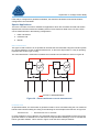
Voltage Adjustments - Vadj
The voltage target of the relay is affected by remote voltage adjustments applied via digital status
inputs or SCADA communications. These adjustments are required for load reduction purposes to
assist the transmission network, and are typically applied as separate +3%, -3% and -6% instructions.
Three status inputs are available on the SuperTAPP n+ for this use with added flexibility for different
applications. The inputs can be configured to operate in two modes:
•
Fixed - adjustments are applied as permanent signals and result in fixed changes to the relay
basic target voltage while the signals are active.
•
Step - adjustments are applied as fleeting signals and result in step changes to the relay basic
target voltage each time a signal is received.
v2.1
Page 26 of 109
SuperTAPP n+ Voltage Control Relay
FIXED ADJUSTMENT MODE
+3%
Vtgt
-3%
Vadj3
OFF
Vadj3
ON
-6%
Vadj1
OFF
Vadj1
ON
Vadj2
OFF
Vadj2
ON
STEP ADJUSTMENT MODE
INCREMENT
PULSE
RESET
PULSE
+1%
+1%
Vtgt
-1%
+3%
-1%
-1%
DECREMENT
PULSE
INCREMENT
PULSE
+2%
RESET
PULSE
DECREMENT
PULSE
DECREMENT
PULSE
Figure 26 – Voltage adjustments
The operating mode of applied voltage adjustments is configured in the relay settings as ‘fixed’ or
‘step’ along with the corresponding values assigned to each of the three status inputs (they are not
limited to 3% and 6% only).
In the case of paralleled transformers, any voltage adjustments should be applied to all controlling
relays, otherwise voltage errors can result along with circulating current (see next section).
Multiple adjustments can be applied simultaneously and result in a summed adjustment to the voltage
target (only valid for ‘fixed’ adjustments). For example, application of +3% (adjustment 1), -3%
(adjustment 2) and -6% (adjustment 3) results in a change to the target voltage of -6%.
See section 10.2.7 for more information relating to status inputs.
8.4
Circulating Current - Vcirc
It is common practice to operate transformers in parallel for security of supply. Paralleled
transformers are usually at the same substation, but not always. Some network operators operate
transformers in parallel across the network.
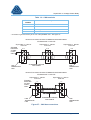
If the open circuit terminal voltages of paralleled transformers are not identical, a circulating current
will flow between them (at a site or across the network). This current will be highly reactive since the
transformers are essentially inductive. Figure 27 shows two paralleled identical transformers at a site,
v2.1
Page 27 of 109
SuperTAPP n+ Voltage Control Relay
T1 and T2, on different tap positions with corresponding vector diagrams. For clarity, load current is
ignored (transformers energised but not on load). T1, being on a higher tap position, will attempt to
produce a higher output voltage than T2 and therefore exports circulating current into T2. The bus-bar
voltage, Vbus, will be the average output voltage of the transformers.
TAP n+1
T1
TAP n
Icirc2
T2
Vbus
Icirc1
Icirc2
Icirc1
Vbus
Figure 27 – Transformer circulating current
Any voltage control relay must include a method to maintain the tap position to the point where
circulating current is minimised, otherwise the tap changers will drift apart and, while the voltage will
be the average of their terminal voltages, a high amount of circulating current will flow between them.
This will cause an unnecessary power loss within the transformers and the network, reducing their
useful capacity and their efficiency. In a worst case this may lead to transformers tripping on high
winding temperature or directional overcurrent, and a complete loss of voltage control.
The SuperTAPP n+ employs the ‘enhanced TAPP’ method to calculate the circulating current (site
and network components) and convert it into a corrective voltage bias, Vcirc. The voltage bias modifies
the target voltage of the relays in order to promote tap changer operations which will reduce the
circulating current to a minimum.
As can be seen from equation 1, negative Vcirc (an export of circulating current), as seen by T1 in
Figure 27, decreases the relay target voltage, making the relay tend to tap down. Positive Vcirc (an
import of circulating current), as seen by T2 in Figure 27, increases the effective target voltage,
making the relay tend to tap up.
The site circulating current is calculated using the ‘true circulating current’ method, which is
dependent on the individual transformer load and the summed load of paralleled transformers. The
network circulating current is calculated using the ‘TAPP’ method (Transformer Automatic Paralleling
Package) which is dependent on the group load and target power factor setting of the relay (typically
0.96 lagging or so).
The circulating currents are then converted into Vcirc using the following relay settings:
•
Transformer rating
•
Firm capacity
•
Transformer % impedance
•
Sensitivity factor for network circulating current*
*the sensitivity factor is included to reduce the errors associated with a fluctuating load power factor (for example
due to embedded generation). The default setting is 10% as a safety margin.
The calculations shown above depend on the group load and therefore the use of CAN bus
communications. It may be that CAN bus communications is not possible, in which case circulating
current will be calculated using the TAPP mode, and the above-mentioned sensitivity factor should be
set to 100%. Alternatively, relays may directly measure the group load using a special CT type (see
section 9.2.1 for more details of the various types of CT function available).
v2.1
Page 28 of 109
SuperTAPP n+ Voltage Control Relay
The calculated values for circulating current and the corresponding voltage bias, Vcirc, can be viewed
in the instrument screens (see
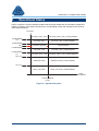
8.5
LDC - VLDC
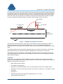
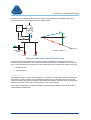
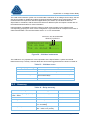
Load drop compensation (LDC) is used to offset voltage drops across a network caused by load
current, as shown in Figure 28.
SEVERAL km's
FEEDER
LDC
LOAD
STATUTORY
VOLTAGE LIMITS
Feeder voltage without LDC
Feeder voltage with LDC
Busbar voltage level
Figure 28 – Load drop compensation (LDC)
The voltage bias for LDC (VLDC) is applied in proportion to the load current and is expressed as a
percentage boost at full load (firm capacity setting). For example, an LDC setting of 10% means that
at full load the voltage boost applied to the relay will be 10% of nominal. At half load, the boost will be
5%.
In order that the voltage is boosted for LDC, the bias to apply to the relay is positive (see equation 1).
LDC is calculated using the following:
•
LDC setting
•
Group load
•
Target power factor (relay setting)
•
Firm capacity (relay setting)
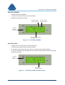
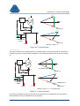
LDC is applied according to the assumed load power factor to minimise the effects of purely reactive
network components such as capacitor banks, heavy industrial loads etc. The effect of this is shown
in Figure 29.
v2.1
Page 29 of 109
SuperTAPP n+ Voltage Control Relay
V
LDC
LOAD
GROUP
LOAD
TARGET
POWER FACTOR
Figure 29 – Application of LDC
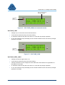
The applied LDC bias is capped at the setting level; it cannot be more than the setting level even if
the group load increases to above the firm capacity setting level.
For situations where the group load is negative, e.g. where there is an excess of connected
generation and the transformers are in reverse power flow, the LDC response is dependent on the
relay setting ‘Reverse LDC’ which gives the following options:
•
OFF – LDC applied is 0%
•
ON – Negative LDC applied as per ‘forward flow’ calculations
The LDC response is shown in Figure 30.
VLDC
LDC
SETTING
FIRM
CAPACITY
-FIRM
CAPACITY
GROUP
LOAD
-LDC
SETTING
Figure 30 – LDC response
The advanced relay model has extra LDC settings available to provide more flexibility for reverse
power such as target power factor and capping levels (see section 9).
v2.1
Page 30 of 109
SuperTAPP n+ Voltage Control Relay
9
Application - Advanced Model Only
9.1
Introduction
The previous application section described features which are available on a basic model (which are
also available on an advanced model). This section describes features which are only available on an
advanced relay.
9.2
Multiple Analogue Inputs
The advanced model of relay has extra VT and CT inputs available to provide enhanced voltage
control for all application complexities. Normally, one CT input is used for measurement of the
transformer load which means that each advanced relay has two spare CT inputs for various uses. All
measurement data is transmitted on the CAN bus and made available to all other connected relays.
In order to make use of the extra VT and CT inputs (i.e. upgrade from a basic model to an advanced
model), an activation code must be purchased from Fundamentals Ltd and entered into the relay
settings.
The extra inputs are used for the following:
1. Feeder current measurements
2. Double-secondary winding transformer measurements
These applications are considered in turn in the following sections.
9.2.1
Feeder Current Measurements
Introduction
Conventional voltage control uses the measured transformer current, usually via the LDC CT, for load
drop compensation and/or circulating current control. These functions have been discussed in
sections 8.4 and 8.5 respectively.
Modern networks have increasing levels of electrical plant connected which can compromise
conventional voltage control due to the injection of real and reactive power (for example embedded
generation, capacitor banks and other reactive support devices). Different types of highly reactive
load can also add to voltage control problems (for example heavy industrial loads which are on in the
day and off at night).
Normally, these items of ‘problem plant’ are confined to individual outgoing feeders, while other
feeders are unaffected. Despite this, the voltage control effect is experienced by all feeders. The relay
has functions available to solve these problems, which rely on the implementation of extra current
measurements on the outgoing feeders which have connected ‘problem plant’.
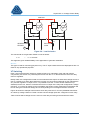
Implementation
The feeder current measurements are facilitated by feeder protection CTs. In order that this does not
compromise the protection scheme, very low burden interposer CT’s are used to interface with the
SuperTAPP n+ relay. These CT’s are 1000:1 ratio wedding ring type with burden < 0.05 VA. The CTs
are described in detail in section 10.2.3.
As discussed earlier, all relay measurements are transmitted on the CAN bus to make them available
for peer units. Functions which make use of these measurements must be applied in the same way to
all relays in the group, otherwise the desired effects will not be realised and voltage errors can occur.
v2.1
Page 31 of 109
SuperTAPP n+ Voltage Control Relay
Special attention therefore needs to be given to relays which are configured for feeder current
measurements so that the data can be available even when the transformers to which they are
connected are switched out (e.g. for maintenance), namely:
1. Power supply
The relay must be powered to continue transmitting measurement data. Normally the auxiliary
AC supply for tap changer control is used to power the control relays and this may be
disconnected if the transformer is switched out, so an alternative is required. The best solution
is to use the DC supply (if available) to power the relay. The SuperTAPP n+ has a flexible
AC/DC input for this use (range is 90 – 240 V AC/DC).
2. Voltage reference.
The relay uses the VT input as a reference for calculation of real and reactive components of
current (see section 4.3). The second VT input of the relay can be configured to use a VT from
another transformer in the group as a voltage reference when the main VT input is lost due to
a transformer switch out. This will be considered in detail in section 9.2.1, ‘VT Switching’.
Definitions
The important relay definitions are as follows:
•
Measured currents – transformers and feeders.
•
Non-measured load – sum of the load on feeders which are not being measured.
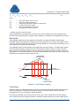
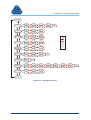
These values can be understood by reference to Figure 31 which shows an application with feeder
measurements on two of the six feeders.
CAN BUS
n+
n+
300 A
300 A
X
100 A
100 A
100 A
100 A
100 A
100 A
NON-MEASURED LOAD
Figure 31 – Definition of non-measured load
v2.1
Page 32 of 109
SuperTAPP n+ Voltage Control Relay
In this case both relays would show the following values in the instruments screens (see section
11.3.1):
Summed transformers
Summed feeder measurements*
Non-measured load
=
=
=
600 A
200 A
400 A
*this data will be presented according to how the CT inputs are configured (see below).
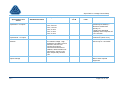
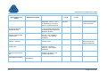
Each CT input used for feeder current measurement must be configured in the settings for a specific
use. There are many uses to choose from, but broadly they can be split into three types, relating to:
1. Embedded Generation.
2. Reactive Sources / Loads.
3. Special Applications.
Each of these types is described in detail in individual sections below.
Embedded Generation
Embedded generation is defined here as generation of any type connected to the network which the
transformer is supplying. The generation can be connected directly to the busbar via one or more
dedicated feeders, or remotely to one or more outgoing feeders. In either case the embedded
generation can cause the following voltage control issues:
1. Reduction in the applied LDC due to reduced transformer current.
2. Voltage rise along feeders to the point of connection when in reverse power flow (i.e. when the
generation exceeds the load on the feeder).
3. Voltage error incurred by inaccurate network circulating current control due to power factor
variations on the transformer current.
In order to solve the above problems the relay has functions available which utilise feeder current
measurements:
1. Accurate LDC based on the ‘true’ group load. With generation present the summed
transformer currents do NOT represent the group load (see figures 32 and 33 below). The
relay can determine generation output(s) based on feeder current measurements and use it to
calculate the ‘true’ group load.
2. Generation compensation – Vgen in equation 1(section 4.4.1). This is a reduction in relay target
voltage in proportion with calculated generation output levels:
Vgen
=
[∑(IG)/Rating] x Genbias
where
∑(IG)
Rating
Genbias
is the measured/calculated generation output (Amps)
is the maximum generator output rating (Amps)
is the %voltage reduction to target at full generator output.
3. Enhanced TAPP circulating current control using the ‘true’ group load.
All of the above-mentioned functions rely on the real-time calculation of the ‘true’ group load and the
generation output. There are two methods for this in respect of how the generation itself is connected
and how the corresponding feeder current measurement inputs are configured in the relay:
1. Direct generator connection – CT input configured as ‘generator’.
v2.1
Page 33 of 109
SuperTAPP n+ Voltage Control Relay
2. Indirect generator connection – CT input configured as ‘generator feeder’.
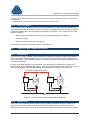
Direct Generator Connection
An example of this application is shown in Figure 32 where two transformers supply a network via 6
feeders and a generator connected directly to the busbar. There is one voltage control relay per
transformer, each of which uses one VT input for voltage measurement and one CT input for
transformer current measurement. One of the relays also uses a CT input for the generator
measurement. All measurement data is available to all relays connected on the CAN bus.
CAN BUS
n+
n+
200 A
200 A
X
200 A
G
100 A
100 A
100 A
100 A
100 A
100 A
Figure 32 – Direct generation connection
Relay 1 and Relay 2
Transformer Current
Summed Transformer Currents
Summed Feeder Measurements
Non-Measured Load
Generator Output
Group Load
=
=
=
=
=
=
200 A
400 A
-200 A
600 A
200 A
600 A
If the bus section is open, the situation changes* as follows:
Relay 1
Transformer Current
Summed Transformer Currents
Summed Feeder Measurements
Non-Measured Load
Generator Output
Group Load
=
=
=
=
=
=
100 A
100 A
-200 A
300 A
200 A
300 A
=
=
=
=
300 A
300 A
0A
300 A
Relay 2
Transformer Current
Summed Transformer Currents
Summed Feeder Measurements
Non-Measured Load
v2.1
Page 34 of 109
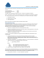
SuperTAPP n+ Voltage Control Relay
Generator Output
Group Load
=
=
0A
300 A
* the group ID of the relays must change to reflect the new configuration (see section 10.2.7 for ‘alternative
settings’).
In order to accommodate all applications to include any number of transformers and generator
connections, the above calculations can be summarised as follows:
Summed Transformer Currents
Generator Output
Group Load
=
=
=
∑(ITn)
∑(IG)
∑(ITn) + ∑(IG)
Indirect Generator Connection
An example of this application is shown in Figure 33 which shows the same network as presented in
Figure 32 but with the generator connected remotely (e.g. several km’s away) to one of the feeders
(called the ‘generation feeder’).
CAN BUS
n+
n+
200 A
200 A
X
IF = -100 A
200 A
G
100 A
100 A
100 A
100 A
100 A
100 A
Figure 33 – Indirect generation connection
The generator feeder has connected load and generation but the feeder current measurement, IF,
cannot discern between them. The example network shows this where the measured feeder current is
-100 A, with 100 A of load and 200 A generation present.
The relay has a generation estimation function which can calculate load and generation present on
the network. The generator estimation function depends on the following:
•
•
Current Measurements
•
Summed Transformer
•
Generator Feeders
Load Ratio
The Load Ratio is a relay setting which is expressed as a percentage and defined as follows:
v2.1
Page 35 of 109
SuperTAPP n+ Voltage Control Relay
Load Ratio = ‘true’ load on generation feeders / load on ‘non-measured’ feeders
The load ratio of the example network shown in Figure 33 is 20%. (100 A / 500 A).
The relevant calculations for the two relays shown in the example network are as follows (all data
presented in the relay instruments to aid troubleshooting):
Relay 1 and Relay 2
Transformer Current
Summed Transformer Current
Generator Feeder Current
Non-Measured Load
Estimated Load
Estimated Generation
Group Load
=
=
=
=
=
=
=
200 A
400 A
-100 A
500 A
100 A
200
600 A
If the bus section is open, the situation changes* as follows:
Relay 1
Transformer Current
Summed Transformer Current
Generator Feeder Current
Non-Measured Load
Estimated Load
Estimated Generation
Group Load
=
=
=
=
=
=
=
100 A
100 A
-100 A
200 A
100 A
200
300 A
Transformer Current
Summed Transformer Current
Generator Feeder Current
Non-Measured Load
=
=
=
=
Estimated Load
Estimated Generation
Group Load
=
=
=
300 A
300 A
0A
300 A (but this is dependent on a new Load Ratio of 0% according
†
to ‘alternative settings’ )
0A
0
300 A
Relay 2
* the group ID of the relays must change to reflect the new configuration (see section 10.2.7for ‘alternative
settings’).
†
in the event of a network configuration change or fault, it is possible to switch the relay to use ‘alternative
settings’. This gives added flexibility so that the relay can be configured appropriately for abnormal operating
conditions. Some examples of how the relay could be configured for abnormal situations are as follows:
•
Revert to ‘safe’ operating mode where feeder current measurements and generator estimation are
ignored
•
Adopt a new load ratio for a specific configuration
•
Switch the relay to non-auto mode (‘tap lock’)
In order to accommodate all applications to include any number of transformers and generator
connections, the above calculations can be summarised as follows:
Estimated Load
Estimated Generation
Group load
=
=
=
Non-Measured Load x Load Ratio
Estimated Load – Generator Feeder Current
Non-Measured Load x (1 + (Load Ratio/100))
The load ratio can be determined from historical load data or from direct measurements. If historical
data is used, the load ratio should be taken as an average value from a period of time over which the
v2.1
Page 36 of 109
SuperTAPP n+ Voltage Control Relay
extent of seasonal variations can be observed. If direct measurement is used to determine the load
ratio it must be ensured that the generation is not running so that the measurement represents the
‘true’ load.
Once the load ratio has been calculated it is configured into the relay settings. It is clear that the
actual load ratio will vary over time due to seasonal variations and network events (outages, faults
etc.). For this reason, the relay settings should be regularly checked to ensure that errors associated
with these variations are kept to a minimum.
The accuracy of the generation estimation algorithm will vary throughout a year and across a network.
Each application will demand an extent of network analysis to optimise the system and minimise
errors. The estimation errors can be eliminated if generator output levels are measured at the point of
connection and made available at the substation SuperTAPP n+ system via an ENVOY unit as shown
in Figure 34.
CAN BUS
ENVOY
n+
n+
GPRS
X
G
ENVOY
CAN
DAM
BUS
Figure 34 – Remote measurements with ENVOY
Generation estimation can be adversely affected by ‘troublesome loads’ connected to the nongeneration feeders. The effect can be mitigated by the use of functions associated with reactive loads
and sources which are described in the next section.
Reactive Loads and Sources
The presence of a load which varies significantly in power factor from the ‘normal’ (target) system
power factor can cause the following issues:
1. Voltage errors incurred by inaccurate LDC.
2. Voltage errors incurred by inaccurate network circulating current control.
3. Generator estimation errors.
v2.1
Page 37 of 109
SuperTAPP n+ Voltage Control Relay
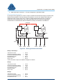
Examples of such loads are capacitor banks, heavy industrial loads and embedded generators.
Figure 35 shows the power factor effect of a capacitor bank.
n+
ITL
Icap
ITL
V
I1
Icap
I2
CAPACITOR
BANK
GROUP LOAD = ITL
I1
LOAD
TARGET pf
I2
LOAD
Figure 35 – Power factor effect of capacitor bank
In order to solve these problems the relay has functions available which utilise feeder current
measurements to calculate the ‘true’ load power factor as accurately as possible and thus minimise
errors. There are options for how these current measurements are configured and used in the relay:
1. Excluded Load.
2. Corrected Load.
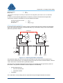
Excluded Load
The simplest solution to power factor problems is to exclude the ‘troublesome’ load completely from
the system as shown in Figure 36. The drawback of doing this is a reduced group load, and care
needs to be taken where LDC is applied so that full boost is applied to the relay at an amended site
capacity (see earlier section 8.5 for a description of how LDC is applied).
If the relay is configured for generator estimation, the load ratio calculation must exclude feeders
configured as excluded loads.
v2.1
Page 38 of 109
SuperTAPP n+ Voltage Control Relay
IF
Icap
n+
V
ITL
I1
TARGET pf
ITL
IF
Icap
CAPACITOR
BANK
V
I1
I2
LOAD
LOAD
-IF
I2
TARGET pf
GROUP LOAD = I2
Figure 36 – Load exclusion
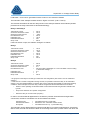
Corrected Load
This type is similar to the excluded load type considered above, except that instead of ‘dumping’ the
measured current, the measurement is ‘adjusted’ to the relay target power factor as shown in Figure
37.
IF
Icap
n+
V
IF-CORRECTED
ITL
TARGET pf
ITL
IF
Icap
CAPACITOR
BANK
I1
LOAD
V
I2
I2
LOAD
-IF
IF-CORRECTED
TARGET pf
GROUP LOAD = I2 + IF-CORRECTED
Figure 37 – Load correction
In this way, the voltage accuracy of the relay is not impaired by the troublesome load, and also the
load information (if any) is maintained for LDC purposes.
v2.1
Page 39 of 109
SuperTAPP n+ Voltage Control Relay
If the relay is configured for generator estimation, the load ratio calculation must exclude feeders
configured as corrected loads.
Special Applications
There are a number of functions available for applications which are somewhat unusual and seldom
experienced, but further extend the flexibility offered. These functions relate to the use of the extra
current measurements in the following configurations:
1. Extra Transformer
2. Included Load
3. Monitor
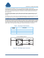
Extra Transformer
This type is used to where it is not possible to calculate the summed loads using the CAN bus system
(e.g. due to distances or lack of cable ducts/trenches, or where the SuperTAPP n+ relay is operating
in parallel with another type of relay).
The ‘extra transformer’ measurement enables the summed load calculation as shown in Figure 38.
n+
n+
X
EXTRA Tx MEASUREMENT
Figure 38 – Extra transformer current measurement
Included Load
As presented earlier, the actual load on generator feeders can be calculated using the non-measured
load and the load ratio setting according to the following for the example network shown in Figure 33:
Estimated Load
=
Non-Measured Load x Load Ratio
In some situations it may be that the non-measured load is not truly representative of the load on the
generator feeders. An alternative is to select the most representative feeder(s) to use to calculate the
load on generator feeders. This is shown in Figure 39 for the same example network.
v2.1
Page 40 of 109
SuperTAPP n+ Voltage Control Relay
CAN BUS
n+
n+
X
Iinc
IF
GENERATOR
FEEDER
INCLUDED
LOAD
G
Figure 39 – Load inclusion
The actual load on the generator feeder is now as follows:
IF-LOAD
=
Iinc x Load Ratio
This approach gives added flexibility to the application of generator estimation.
Monitor
This type is used for monitoring purposes only. The CT input measurements are displayed but are not
used for any operational purposes.
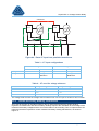
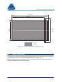
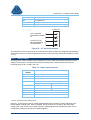
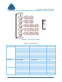
VT Switching
Each current measurement requires a voltage reference for calculation of the real and reactive
components (see section 4.3). Normally this comes from the VT on the transformer which the relay
uses for regulation.
Relays which are configured for feeder current measurements require an alternative voltage source to
use as a reference for when the transformer to which it is connected is switched out (for maintenance
etc.) and the regulation VT input is lost. It is possible to use the VT from another transformer (if
available) for this use, where it is wired to the second VT input of the relay and configured as ‘voltage
reference’. If no back-up voltage source is available, the feeder current measurement information will
be lost during the transformer outage and a corresponding error message and alarm will result.
Figure 40 shows an example scheme where each relay uses the VT from the paralleled transformer
as a back-up voltage reference. Table 3 shows how the voltage inputs are configured on each relay.
Table 4 shows which voltage source is used on each relay according to the transformer status.
v2.1
Page 41 of 109
SuperTAPP n+ Voltage Control Relay
CAN BUS
n+1
n+2
VT-1
VT-2
X
Figure 40 – Extra VT input from paralleled transformer
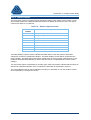
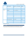
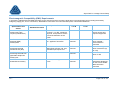
Table 3 – VT input configurations
Relay 1
Relay 2
VT Connected
VT Use
VT Connected
VT Use
VT Input 1
VT-1
Voltage Control
VT-2
Voltage Control
VT Input 2
VT-2
Voltage
Reference
VT-1
Voltage
Reference
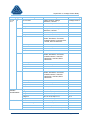
Table 4 – VT used for voltage reference
Active Transformers
Relay 1 Voltage Reference
Relay 2 Voltage Reference
T1 & T2
VVT-1
VVT-2
T1
VVT-1
VVT-1
T2
VVT-2
VVT-2
The voltage level at which the voltage source switches from one VT input to another is 80% nominal.
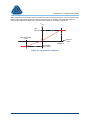
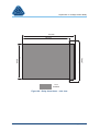
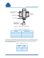
9.2.2
Double-Secondary Winding Transformers
Since the tap changer is normally located on the HV side of the transformer (single winding),
regulation of transformers with two secondary windings requires the calculation of the average of the
measured secondary voltages and the sum of the loads on each winding. Two VT inputs and two CT
inputs are therefore required for control of double-secondary winding transformers, as shown in
Figure 41.
v2.1
Page 42 of 109
SuperTAPP n+ Voltage Control Relay
n+
X
Figure 41 – Double secondary winding transformer
In order to implement voltage averaging, each VT input must be configured as ‘voltage control’ and
each CT input as ‘transformer’ in the settings. The calculated average voltage is used as VVT to
compare with the relay target voltage as shown earlier in Figure 5. The summed transformer load is
used to calculate the group load and in turn for LDC and circulating current functions as discussed in
sections 8.4 and 8.5.
Where the measured voltage on a VT input falls below 80% nominal voltage (for example in the event
of a fuse failure), the relay will automatically revert to using the remaining VT for voltage control.
Voltage averaging will resume once the other VT input recovers back to above the 80% level.
The relay will alarm if the voltages as measured by the two VT inputs differ by more than 10% in
magnitude or 20° in angle.
9.3
Advanced LDC
As already discussed in section 8.5, Load drop compensation (LDC) is a voltage boost used to offset
voltage drops across a network caused by load current. Where the load on the transformer is in
reverse power flow (due to embedded generation), it may be beneficial to apply a voltage reduction as
‘reverse LDC’. The basic relay model can be configured to apply reverse LDC in such a way that
mirrors the forward power flow response (see Figure 30).
The advanced relay model has extra LDC settings available to provide more flexibility for reverse
power. The target power factor which the relay uses to calculate the LDC response can be modified
for reverse power as shown in Figure 42. The relevant setting is called ‘reverse power factor’.
REVERSE POWER
FACTOR
LDC LOAD
V
GROUP LOAD
TARGET POWER FACTOR
('FORWARD' POWER)
Figure 42 – LDC for reverse power
v2.1
Page 43 of 109
SuperTAPP n+ Voltage Control Relay
Other settings for reverse LDC are ‘max reverse load’ and ‘reverse LDC level’. The ‘max reverse load’
defines the group load level at which the ‘reverse LDC level’ is applied. These settings allow the
reverse LDC response to differ to the ‘forward’ LDC response, as shown in Figure 43.
VLDC
LDC
SETTING
MAX REVERSE
LOAD
0
0
FIRM
CAPACITY
GROUP
LOAD
REVERSE
LDC LEVEL
Figure 43 – Reverse LDC response
v2.1
Page 44 of 109
SuperTAPP n+ Voltage Control Relay
10
Specification
10.1
Hardware
The relay is housed in a 1 mm mild steel anodised case finished in an over baked powder coating. A
transparent cover is fixed to the front of the relay for normal operation. With the cover in place, the
user can observe fascia indications and read the LCD, but can also push the control knob to view
some instruments. Where settings need to be amended or more detailed instruments viewed, the user
must remove the cover such that the control knob may be turned.
Figure 44 to Figure 47 show the relay dimensions in front, rear, plan and side views.
v2.1
Page 45 of 109
SuperTAPP n+ Voltage Control Relay
145 mm
135 mm
157 mm
177 mm
4 LINE LCD
CONTROL
KNOB
5 mm PANEL
FIXING HOLES
93 mm
1 mm CASING
RELAY
Figure 44 – Relay dimensions – front view
v2.1
Page 46 of 109
SuperTAPP n+ Voltage Control Relay
145 mm
135 mm
INTERNAL
CASE
FIXING
157 mm
177 mm
EARTHING
STUD
1 mm CASING
RELAY
RELAY
CONNECTORS
Figure 45 – Relay dimensions – rear view
v2.1
Page 47 of 109
SuperTAPP n+ Voltage Control Relay
215 mm
191 mm
FRONT
177 mm
157 mm
REAR
1 mm
CASING
Figure 46 – Relay dimensions – side view
v2.1
Page 48 of 109
SuperTAPP n+ Voltage Control Relay
215 mm
191 mm
FRONT
145 mm
REAR
135 mm
1 mm
CASING
Figure 47 – Relay dimensions – bird’s eye view
10.2
Relay Connections
All connections to the relay are made at the rear through Phoenix type connectors. The connections
are grouped by function and numbered alphabetically (shown in Figure 48).
Each group of connections is considered in turn in the following sections with tables describing the
functions and diagrams showing implementation.
v2.1
Page 49 of 109
SuperTAPP n+ Voltage Control Relay
F1
C1
A1
F2
C2
A2
F3
C3
A3
F4
C4
A4
F5
A5
F6
A6
CONNECTOR
TERMINAL BLOCK
F7
F8
D1
D2
D3
EARTHING
STUD
D4
D5
D6
D7
D8
B1
B2
G1
E1
B3
G2
E2
B4
G3
E3
B5
G4
E4
B6
ONLY USED ON
ADVANCED MODEL
Figure 48 – Relay connections
10.2.1 Power Supply
The relay is designed with flexibility in mind. The switched-mode power supply employed has a wide
voltage operating range of 80V AC to 260V AC and 90V to 140V DC. The maximum power
consumption is 5W.
Table 5 – Power supply terminals
Terminal
number
v2.1
Description
A1
Safety Earth
A2
Safety Earth
A3
Supply Voltage (+)
A4
Supply Voltage (+) for Looping
A5
Supply Voltage (-)
A6
Supply Voltage (-) for Looping
Page 50 of 109
SuperTAPP n+ Voltage Control Relay
80-260V AC / 90-140 V DC
POWER SUPPLY
A3
A4
A1
A5
PSU
A6
A2
ALTERNATIVE CONNECTIONS A1, A4 AND A6
MAY BE USED IF REQUIRED BUT REMOVING
THE PLUG BREAKS THE INTERNAL LINKING
Figure 49 – Power supply connections
10.2.2 Current Measurement Inputs
Three current inputs are available for use with any phase mounted CT. Two types of current
measurement are possible; transformer current (via the transformer LDC CT) and feeder current (via
breaker CT). In traditional AVC applications only the former are used (basic relay model). For
advanced AVC applications, such as schemes with embedded generation, both types are used
(advanced relay model).
Table 6 – CT terminals
Terminal
number
v2.1
Description
B1
CT1 S1
B2
CT1 S2
B3
CT2 S1
B4
CT2 S2
B5
CT3 S1
B6
CT3 S2
Page 51 of 109
SuperTAPP n+ Voltage Control Relay
HV
LOAD
P1
S1
B1
S2
INTERPOSING CT
1000/1 0.1 VA
CT1-S1
P2
LDC CT
ANY PHASE
ANY DIRECTION
CT INPUTS
B2
P2
B3
CT2-S1
B4
INTERPOSING CT
1000/1 0.1 VA
P1
S2 S1
CT2-S2
P2
ADDITIONAL CT
MEASUREMENTS
FOR OTHER USES
AS REQUIRED
INTERPOSING CT
1000/1 0.1 VA
P1
S2 S1
CT1-S2
B5
CT3-S1
B6
CT3-S2
Figure 50 – CT connections
Normally, feeder current measurements are only possible using protection CT’s. In order that the
protection scheme is not compromised, low burden interposer CT’s are used to interface with the
relay. The use of such interposers gives the following additional advantages:
•
Safety – no risk of high voltages for open-circuit (clamped at around 11 V)
•
Flexibility – accuracy can be ‘tuned’ by additional interposer turns
The SuperTAPP n+ relay is designed for use with a low burden interposer CT for all current
measurements. The interposers are supplied with the relay, and are described in more detail in the
following section.
10.2.3 Interposer CT
The interposer CT designed for use with the SuperTAPP n+ voltage control system provides a high
level of electrical isolation between the source current circuitry. It imposes virtually no burden upon
the measurement current transformer (< 0.05 VA).
Figure 51 and Figure 52 give an external view of the interposer unit. The device is mounted in a DIN
rail type enclosure with screwed terminal output connections available from either side of the unit.
v2.1
Page 52 of 109
SuperTAPP n+ Voltage Control Relay
CT isolation unit
Type FP1030
S1
Ser. No.
S1
Fundamentals Ltd
www.fundamentalsltd.co.uk
P1
UNIVERSAL
MOUNTING FOOT
MAY BE REVERSED
IF REQUIRED
G-RAIL
MOUNTING
POSITION
Figure 51 – Interposer CT
The primary conductor (S1 from primary CT) is passed through a central hole in the casing as shown
in figures 51 and 52. The enclosure is mounted on the reversible universal foot that will allow fixing
onto either a G-rail or DIN-rail mounting arrangement.
The interposer CT should be mounted in a convenient position such that the distance between the
unit and the relay is at a practical minimum. If there is substantial distance between the unit and the
device, a twisted pair cable should be used. This may be the case where a protection CT is utilised. In
this instance the interpose CT should be mounted as close as possible to the primary CT secondary
wiring and in any event in the same panel. The specification for the interposer CT is shown in table 7.
v2.1
Page 53 of 109
SuperTAPP n+ Voltage Control Relay
S2
S1
P2
P1
n PASSES THROUGH
CT ISOLATION
FROM CT
CIRCUIT
35 MM DIN RAIL
S2
S1
CT ISOLATOR
TWISTED PAIR TO
REMOTE TAP
CHANGE PANEL
Figure 52 – Interposer CT connections
Table 7 – Interposer CT specification
Parameter
Specified value
Ratio
10A : 0.01 A
Maximum primary current
10 A
Burden
0.03 VA
Isolation
> 3 kV
Material
UV 94-V-0 polyamide 66/6
The maximum current that the device can measure with accuracy is 10 amps. Depending on the use
of the interpose unit, turns can be added to the primary side in order to increase the sensitivity of the
output. It is recommended that the number of turns should give ‘5 Amp turns’ at rated current as
shown in Table 8 and Figure 52.
Table 8 – Interposer CT turns
CT
secondary
rating
v2.1
Interposer
turns
required
5A
1
1A
5
0.5 A
10
Page 54 of 109
SuperTAPP n+ Voltage Control Relay
In situations where the loading on the CT is low compared to the rating, accuracy can be
compromised. The number of turns on the interposer can be increased to improve the accuracy, but
care is required and in any case it is not recommended to increase the number of turns above 5 Ampturns at the normal maximum loading level. The maximum non-fault overload level should be less
than 10 Amp-turns.
For example, a feeder breaker CT (ratio 1000:5) would normally have a single interposer turn. If the
maximum loading of the feeder is 200 A, the number of turns could be increase to 5 to give more
accuracy.
The settings for each CT input need to be configured appropriately in order that the relay can convert
the measurements into the correct primary values (see CT settings in section 11.3.2).
10.2.4 Tap Changer Outputs
The raise and lower outputs are used to initiate a tap change when the measured voltage is outside of
the ‘dead band’. Normally a raise will increase the tap position and the measured voltage, and a lower
vice-versa. However, tap changers can sometimes work in the opposite direction where an increase
in tap position will produce a lower voltage. The outputs should be wired such that raise produces a
higher voltage. These outputs have normally open contacts and are rated 12 A continuous.
Table 9 – Tap changer output terminals
Terminal
number
Description
C1
Lower Tap Pulse
C2
Common
C3
Common
C4
Raise Tap Pulse
110 V AC CONTROL CIRCUIT
RAISE /LOWER OUTPUTS
C2 RAISE
C4
C3 LOWER C1
RAISE TAP RELAY
LOWER TAP RELAY
Figure 53 – Tap changer output connections
v2.1
Page 55 of 109
SuperTAPP n+ Voltage Control Relay
10.2.5 Status Outputs
The relay has a number of outputs used to indicate the status of the voltage control system. These
are normally wired into the telecontrol/SCADA scheme for display at the control room. The output
contacts are rated 12 A continuous.
Table 10 – Status output terminals
Terminal
number
Description
D1
Relay Healthy Common
D2
Relay Healthy
D3
Relay Fail
D4
AVC Alarm Common
D5
AVC Alarm
D6
Control Mode (Non-Auto)
D7
Control Mode Common
D8
Control Mode (Automatic)
The Relay Healthy output is used to indicate the health status of the relay with an associated
changeover contact for operational indication. The Relay Healthy contact will be closed when the
relay is healthy. The Relay Fail contact will be closed when the relay is either powered down or has
problems associated with hardware (in either case the relay is not operational and cannot control
voltage).
The AVC Alarm output is operated by a normally open contact and used to indicate that the relay has
detected an operational problem. Error conditions are described in more detail in section 7.
The Control Mode output is used to indicate if the relay is in automatic or non-auto mode of control
and is operated by a changeover contact.
v2.1
Page 56 of 109
SuperTAPP n+ Voltage Control Relay
SUPPLY
RELAY STATUS
D1 HEALTHY D2
D3
ALARM
SUPPLY
CONTROL MODE
D7
AUTO D8
D6
NON-AUTO
SUPPLY
AVC ALARM
D4 ALARM D5
Figure 54 – Status output connections
10.2.6 Voltage Measurement Inputs
Two nominal 110V AC inputs for voltage measurements are provided rated for up to 150 V AC. The
burden imposed on the VT by the relay is less than 1VA. In most schemes only a single voltage input
will be used (basic relay model).
The second input is used on the advanced relay model for applications involving double-secondary
winding transformers where voltage averaging and load summation is required. It will also be used for
applications where a ‘back-up’ phase reference is required for feeder current measurements. These
applications are described in more detail in section 9.
Table 11 – VT input terminals
Terminal
number
v2.1
Description
Page 57 of 109
SuperTAPP n+ Voltage Control Relay
E1
VT1 (phase 1)
E2
VT1 (phase 2)
E3
VT2 (phase 1)
E4
VT2 (phase 2)
VT INPUTS
E1
ANY 2 PHASES
FROM MEASURING
VT
VT1(P1)
E2
VT1(P2)
E3
OTHER VT FOR
MEASUREMENTS
AS REQUIRED
VT2(P1)
E4
VT2(P2)
Figure 55 – VT input connections
The settings for each VT input (such as VT ratio and VT phase) need to be configured appropriately in
order that the relay can convert measurements into the correct primary values (see settings in section
11.3.2).
10.2.7 Status Inputs
The relay has a number of status inputs available for use to modify the operating parameters of the
voltage control system. The inputs are wired into the telecontrol / SCADA scheme and have an
operating range of 20 V to 250 V AC / DC.
Table 12 – Status input terminals
Terminal
number
Description
F1
Voltage Adjustment 1
F2
Voltage Adjustment 2
F3
Voltage Adjustment 3
‘Auto Select Mode’ Setting *
Level Detect
Edge Detect
F4
Remote/Local
Non-Auto
F5
Auto /Non-Auto
Auto
F6
Alternative Settings
F7
Common
F8
Common
* found in the ‘Relay Config’ settings menu
Inputs F1, F2 and F3 are used for voltage target adjustments, normally for voltage reduction when
load shedding is taking place. When energised, the inputs result in a change to the relay target
voltage level. See section 8.3 for detail of how the voltage adjustments operate (the inputs can be
configured to respond to permanent or fleeting signals).
v2.1
Page 58 of 109
SuperTAPP n+ Voltage Control Relay
The function of status inputs F4 and F5 is dependent on the ‘Auto Select Mode’ setting as shown in
Table 12. Where the setting is set to ‘level detect’ (permanent signal), F4 functions as Remote (signal
on) / Local (signal off) and F5 as Auto (signal on) / Non-Auto (signal off). Where the setting is set to
’edge detect’ (fleeting signal), F4 functions as Non-Auto, F5 as Auto (no facility for Remote/Local).
Input F6 is used to switch the relay to use a different set of key settings as defined in the ‘Alternative
Settings’ menu and shown in Table 13. These settings are used while the status input is energised
(permanent signal).
Table 13 – Alternative settings
Setting
Type
Alternative
Settings
Setting
Range
Default
setting
Target voltage
90 % - 110 % step 0.1 %
100 %
Bandwidth
0.5 % - 5 % step 0.1 %
1.5 %
LDC
0 % - 20 % step 0.1%
2.5%
Reverse LDC
On/Off
Off
Group ID
1–6
1
Load Ratio *
0 – 200 %
0%
Generator Bias *
0 – 10% step 0.1 %
0%
Firm Capacity
50 – 10000 step 1
1575 A
Power Factor
0.5 lag – 1.0 – 0.9 lead
0.96 lag
Reverse Power Factor*
Disabled, -0.5 lag - -0.5 lead
step 0.01
Disabled
Reverse LDC Level*
Disabled, -0.1% - -20% step
0.1%
Disabled
Max Reverse Load*
Disabled, -50 A - - 10000 A
step 1
Disabled
Network Circ. Factor
10 – 100 %, step 1%
10%
Feeder Measurements *
Use or Ignore
Ignore
* Not shown for a ‘basic’ model
Alternative settings are intended to offer flexibility for abnormal operating conditions such as:
•
Topology changes – where transformers which are normally operated in parallel are
temporarily switched apart by opening of a bus section for example. In this situation it will be
necessary to alter the group ID of at least one unit (see section 4.6.3 for a description of this).
•
Network changes – where the configuration of outgoing feeders is changed and require
different settings (e.g. LDC settings).
The alternative settings may be particularly useful for the more ‘advanced’ applications where extra
CT and VT measurements are in use and where ‘safe AVC’ can be applied in the event of abnormal
conditions.
v2.1
Page 59 of 109
SuperTAPP n+ Voltage Control Relay
110 V AC TAP CHANGE CONTROL CIRCUIT
1ST VOLTAGE OFFSET RELAY
DIGITAL INPUTS
F1
F7
V OFFSET 1
2ND VOLTAGE OFFSET RELAY
F8
F2
V OFFSET 2
3RD VOLTAGE OFFSET RELAY
F3
V OFFSET 3
SELECT NON-AUTO CTRL RELAY
F4
NON-AUTO
SELECT AUTO CTRL RELAY
F5
AUTO
SELECT ALTERNATIVE
SETTINGS RELAY
F6
PARAM SELECT
Figure 56 – Status input connections
10.2.8 CAN Bus Communications
The CAN Bus is used for communications between SuperTAPP n+ relays to allow distribution of
status and measurement information. For single transformer applications it is not used. For multiple
transformer applications it allows the determination of summed measurements and calculation of
values which are important for AVC functions.
Each relay is connected by screened twisted pair cable in a daisy chain configuration. Relays at each
end of the chain need to have a link in place between the ‘CAN Low’ (G2) terminal and the ‘CAN
Termination’ terminal (G4). Correct CAN bus connections for two and three relay applications are
shown in Figure 57.
v2.1
Page 60 of 109
SuperTAPP n+ Voltage Control Relay
Table 14 – CAN terminals
Terminal
number
Description
G1
CAN Ground*
G2
CAN Low
G3
CAN High
G4
CAN Termination
* connection to ground must only be on one of the paralleled units – see Figure 57.
DETAILS OF PEER TO PEER COMMUNICATION BETWEEN
3 SUPERTAPP n+ RELAYS
SuperTAPP n+ RELAY
FOR TX1
SCREEN
n+1
EARTHED
AT ONE
G1
POINT
ONLY
G2
LINE
TERMINATOR
LINK
SuperTAPP n+ RELAY
FOR TX2
SuperTAPP n+ RELAY
FOR TX3
n+2
n+3
G1
G1
G2
G2
G3
G3
G3
G4
G4
G4
SCREENED TWISTED
PAIR CABLE
LINE
TERMINATOR
LINK
DETAILS OF PEER TO PEER COMMUNICATION BETWEEN
2 SUPERTAPP n+ RELAYS
SuperTAPP n+ RELAY
FOR TX1
SCREEN
n+
EARTHED
AT ONE
G1
POINT
ONLY
G2
LINE
TERMINATOR
LINK
SuperTAPP n+ RELAY
FOR TX2
n+
G1
G2
G3
G3
G4
G4
SCREENED TWISTED
PAIR CABLE
LINE
TERMINATOR
LINK
Figure 57 – CAN bus connections
v2.1
Page 61 of 109
SuperTAPP n+ Voltage Control Relay
The CAN communications system can accommodate a maximum of six voltage control relays, but can
also accommodate an additional six Data Acquisition Modules (DAM’s) where extra feeder current
measurements are required for advanced applications (see section 9). The DAM is based on
SuperTAPP n+ hardware, with the same form factor but different inputs and outputs. Please refer to
the DAM technical literature for more information.
Instrumentation is available to show the number of units communicating on the CAN bus with
corresponding groupings to check correct configuration. Figure 58 shows an example screen shot of
CAN instrumentation. See the instruments section 11.3.1 for more details.
RELAYS 2 & 3 IN DIFFERENT
GROUP TO RELAY 1
COMMUNICATIONS
Txs on bus
ஏஏஏ--Txs in group ஏ----Figure 58 – CAN bus instruments
The CAN bus is very important for correct operation of the SuperTAPP n+ system and should
therefore be set up correctly. CAN bus faults and errors with suggested fixes are shown in Table 15.
Table 15 – CAN bus errors
Relay display message
10.3
Remedy
Communications error
Check diagnostic instruments and CAN bus wiring
Comms ID clash
Check transformer ID setting
Comms data missing
Check diagnostic instruments and for errors or power
fail on other relays
DAM error
Check for errors on connected DAM units
Accuracy
Table 16 – Relay accuracy
Quantity
Range
Tolerance
Operating voltage range (RMS)
47Hz – 63Hz
80% - 120% of target
±0.2%
Bandwidth
±0.5% - ±5%
±0.1%
No voltage detection
<25% of target
±1%
Power Factor
1 – 0.5 lead/lag
0.5 – 0 lead/lag
±1%
Current (RMS)
5% - 20% x CT primary
20% - 200% x CT primary
±2% of nominal
v2.1
Page 62 of 109
SuperTAPP n+ Voltage Control Relay
LDC
0% - 10%
±0.2%
Initial time delay
Through range
±1 sec
Inter-tap delay
Through range
±1 sec
Over-current blocking
50% - 200%
±5%
10.4
Type Tests
The SuperTAPP n+ has been tested in accordance with the Energy Networks Association (ENA)
Technical Specification EATS 48-5 Issue 2 2000, ‘Environmental Test Requirements for Protection
Relays and Systems’. This test specification was produced by the Electricity Association Protection
Panel in consultation with manufacturers of protection equipment and applies to equipment intended
for use within the UK electricity supply industry.
The specification recommends atmospheric, mechanical, electrical and EMC tests to be performed
according to specified standards. Details and results of these tests are presented in Appendix D.
v2.1
Page 63 of 109
SuperTAPP n+ Voltage Control Relay
11
HMI
11.1
Relay Fascia
The SuperTAPP n+ has been designed with the user in mind, with a simple front display and
meaningful fascia indications. A single control knob allows navigation through the menu system and
application of settings. Comprehensive instruments are included to provide measurement, status and
diagnostic information, allowing the user to fully observe and understand relay operation. The relay
fascia is shown in Figure 59.
A
HIGH
G
F
E
VOLTAGES
Basic targt 11.00 kV
Calc target 11.00 kV
Measured
0.00 kV
B
TAP
LOW
SuperTAPP n+
PRESS
VOLTAGE
CONTROL
RELAY
TURN
C
INSTRUMENTS
D
SETTINGS
FAULTS
Model
Fundamentals Ltd
Ser.No.
www.fundamentals.co.uk
Figure 59 – Relay fascia
A. Four line LCD for display of measurement and status information
B. Tap in progress indication LED
C. Control knob for menu system navigation and settings changes
D. LED indications for menu system navigation
E. Voltage low (solid) / Voltage very low (flashing)
F. Normal voltage (solid) / Overload (flashing)
G. Voltage high (solid) / Voltage very high (Flashing)
v2.1
Page 64 of 109
SuperTAPP n+ Voltage Control Relay
The relay has LED indications on the fascia and a four-line LCD with backlighting. The backlighting is
activated by a push of the control knob and deactivated after 5 minutes of inactivity.
11.2
Display Messages
Table 17 – Display messages
Relay Message
Description
Hardware error
There is a problem with the relay hardware. Please contact Fundamentals
for support.
Measurement error
There is a problem with a voltage or current measurement. Please contact
Fundamentals for support.
Uncalibrated input
One of the voltage or current inputs is not calibrated. Please contact
Fundamentals for support.
Overloaded input
One of the voltage or current inputs is overloaded. The maximum
measurements are 150 Volts or 10 Amp-turns.
Mismatched VT inputs
The signals on the two voltage inputs differ by more than 10% in
magnitude or 20° in angle. Please check your VT and CT settings.
Comms ID clash
Two relays have been set to the same Transformer ID. They are unable to
exchange data.
Communications error
Data is unexpectedly no longer being received from another relay. Please
check your CAN wiring.
DAM error
A connected Data Acquisition Module has experienced a fault.
Comms data missing
A connected relay has been powered off or is unable to make
measurements.
Over current
The measured transformer current is greater than the set overcurrent
level. Tap changes are inhibited.
Zero voltage
The measured transformer voltage is less than 25% of target. Automatic
control is inhibited.
Under voltage
The measured transformer voltage is less than 80% of target. Automatic
control is inhibited.
Voltage out of band
The measured transformer voltage is outside the set bandwidth and
automatic control is disabled.
Auto ctrl disabled
Automatic voltage control is disabled.
Time to tap
The relay is timing down to a tap change.
Raising voltage
The relay is issuing a ‘tap up’ command.
Lowering voltage
The relay is issuing a ‘tap down’ command.
Preparing switch out
The relay is preparing the transformer to be switched out.
Ready to switch out
The transformer is ready to be switched out.
11.3
Menu System
Various screens are displayed on the LCD via the menu system. Navigation through the menu system
is provided using the control knob (push and turn) on the relay fascia. The default screen can be
accessed at any time by pressing and holding the control knob in for more than 1 second (this will
cancel any unsaved settings changes). The relay will automatically return to the default screen after
10 minutes of inactivity.
v2.1
Page 65 of 109
SuperTAPP n+ Voltage Control Relay
The display menu system is accessed from the default screen and has three top-level items, each
with a corresponding LED on the relay fascia:
•
Instruments
•
Settings
•
Faults
With the relay lid in place, the user is limited to push button control (no turn) and can only view the
summary instruments screens. With the lid off, the user can turn and push the button and is free to
navigate throughout the menu system. Figure 60 shows the structure of the menu system (each menu
item shown contains sub-menus). The contents of each menu item are described in detail in the
following sections.
DEFAULT
SCREEN
LCD
BACKLIGHT
SUMMARY
SUMMARY
MEASUREMENTS
CALCULATIONS
EXIT MENU
BASIC
SETTINGS
BASIC
NETWORK
TRANSFORMER
VT'S & CT'S
VOLT TARGET
ADJUST
EXIT MENU
RELAY CONFIG.
ALTERNATIVE
ALARMS
GENERATION
RELAY ALARMS
AVC ALARMS
EXIT MENU
INSTRUMENTS
DIAGNOSTICS
SETTINGS
FAULTS
BUTTON
PUSH
EXIT
BUTTON
TURN
Figure 60 – Menu system
11.3.1 Instruments
The instruments menu allows the user to view system data that give measured and calculated values.
The menu is shown in Figure 61. The displayed data is described in Table 18.
v2.1
Page 66 of 109
SuperTAPP n+ Voltage Control Relay
INSTRUMENTS
VOLTAGES
CURRENTS
STATUS INPUTS
OUTPUT RELAYS
PRIMARY
VOLTAGES
PRIMARY
CURRENTS
CT TYPES *
SECONDARY
VOLTAGES
SECONDARY
CURRENTS
VOLTAGES
VOLTAGE
BIASES
CIRCULATING
CURRENTS
CALCULATED
LOADS
GROUP LOAD
SUMMED
SUMMED
NUMBER
MEAS.*
MEAS.*
SPECIAL CT'S *
RESTARTS
PRODUCT
VERSION
CALIBRATION
DATA ANG.
CALIBRATION
DATA MAG.
TARGET
VOLTAGE
GROUP ID
LOAD RATIO *
SUMMARY
MEASUREMENTS
STATUS
IMPUTS
STATUS INPUTS
CALCULATIONS
EST GEN
FEEDER
VALUES *
CAPACITIES
TAP COUNTER
COMMS*
COMMS*
COMMS
COMMS
CALCULATIONS
CURRENT
MEAS.
DIAGNOSTICS
REMOTE
†
SETTINGS
BUTTON
PUSH
BUTTON
TURN
† ONLY SHOWN
WHEN ENVOY
PRESENT ON
CAN BUS
EXIT
* NOT SHOWN
ON BASIC
MODEL
Figure 61 – Instruments structure
Table 18 – Instruments details
Instrument
Summary
Name
VOLTAGES
Display Data
Comments
Basic target (kV)
Calc. target (kV)
Measured (kV)
CURRENTS
Group load (A /pf)
Generator (A / pf) *
Site circ. (A)
STATUS INPUTS
Remote (On) / Local (Off) OR
Auto (On/Off)*
- = Off
█ = On
Auto (On) / Non-auto (Off) OR
Non-auto (On/Off)*
Alternative settings (On/Off)
V targ1 / V inc (On/Off)
V targ2 / V dec (On/Off)
V targ3 / V reset (On/Off)
OUTPUT RELAYS
Raise (On/Off)
Lower (On/Off)
- = Off
█ = On
Auto (On/Off)
Healthy (On/Off)
AVC alarm(On/Off)
v2.1
Page 67 of 109
SuperTAPP n+ Voltage Control Relay
Instrument
Measurements
Name
PRIMARY
VOLTAGES
Display Data
Comments
V1 (kV)
V2 (kV) *†
Phase reference (V1 / V2) *†
PRIMARY
CURRENTS
C1 (A / pf )
C2 (A / pf ) *†
C3 (A / pf ) *†
CT TYPES *
C1 Type *
C2 Type *†
C3 Type *†
SECONDARY
VOLTAGES
V1 (V / ˚ )
V2 (V / ˚ ) *†
Phase reference *†
SECONDARY
CURRENTS
C1 (mA / ˚ )
C2 (mA / ˚ ) *†
C3 (mA / ˚ ) *†
STATUS INPUTS
Remote (On) / Local (Off) OR
Auto (On/Off)◊
− = Off
█ = On
Auto (On) / Non-auto (Off) OR
Non-auto (On/Off) ◊
Alternative settings (On/Off)
V targ1 / V inc (On/Off)
V targ2 / V dec (On/Off)
V targ3 / V reset (On/Off)
OUTPUT RELAYS
Raise (On/Off)
Lower (On/Off)
− = Off
█ = On
Auto (On/Off)
Healthy (On/Off)
AVC alarm (On/Off)
Calculations
VOLTAGES
Basic target (%)
Calc. target(%)
Measured (%)
VOLTAGE BIASES
Circ. current (%)
LDC (%)
Generator (%) *
CIRCULATING
CURRENTS
Site (A)
Network (A)
CALCULATED
LOADS
Group (A/pf)
Generator (A/pf) *
GROUP LOAD
MVA
MW
v2.1
Page 68 of 109
SuperTAPP n+ Voltage Control Relay
Instrument
Name
Display Data
Comments
Mvar
Diagnostic
Instruments
CURRENT
MEASUREMENTS
SUMMED
MEASUREMENTS *
SUMMED
MEASUREMENTS *
Transformer (A/pf)
Summed transformers (A/pf)
Generator feeders (A/pf) *
Generators (A/pf) *
Excluded loads (A/pf) *
Corrected loads (A/pf) *
Included loads (A/pf) *
NUMBER SPECIAL
CT’S *
Generator feeders *
Generators *
Extra transformers *
Excluded loads *
Included loads *
Corrected loads *
CALCULATIONS *
Non-measured load (A/pf) *
ESTIMATED
GENERATOR
FEEDER VALUES *
Load (A/pf) *
Generation (A/pf) *
CAPACITIES
Generation (A) *
Summed transformer ratings
(A)
TAP COUNTER
No. of taps
COMMUNICATIONS
Transformers on bus
Transformers in group
COMMUNICATIONS
Transformers missing
Transformers off
Transformers in error
COMMUNICATIONS *
DAM’s on bus *
DAM’s in group *
COMMUNICATIONS *
DAM’s missing *
DAM’s off *
DAM’s in error *
CALIBRATION DATA
MAGNITUDE
V1
V2 *
C1
C2 *
C3 *
CALIBRATION DATA
ANGLE
V1
V2 *
C1
C2 *
v2.1
Page 69 of 109
SuperTAPP n+ Voltage Control Relay
Instrument
Name
Display Data
Comments
C3 *
PRODUCT VERSION
Product ID
Article number
Compile time
RESTARTS
Number of restarts
Uptime
Reason
Remote Settings
VIEW REMOTE
SETTINGS
Target voltage (%)
Group ID
Load ratio (%)
* Not shown for a basic model
†
Not shown if inputs are set to ‘Unused’ on an advanced model
◊ Dependent on the ‘Auto select mode’ setting
11.3.2 Settings
The settings menu allows the user to view and amend relay settings. The full settings menu is shown
in Figure 63. Settings data with default values and ranges is shown in Table 19.
Edit Mode
Edit mode is selected by pressing the control knob when the setting to be amended is displayed on
the screen. In this mode the user can turn the control knob to change the setting. Some settings with
wide ranges have coarse and fine adjustments to reduce the number of control knob turns required.
Other settings have a fixed number of options to choose from.
When the desired setting value/option is attained, the control knob is pushed to store the new value in
memory and exit edit mode. The user can move to other settings within the setting menu for edit, or
proceed to exit the setting menu, at which point the user has two options:
•
Save change and exit
•
Reject changes and exit
An example of the setting changes screen is shown in Figure 62.
BASIC SETTINGS
Apply & exit
Cancel & exit
Page 9 of 9
Figure 62 – Settings change
v2.1
Page 70 of 109
SuperTAPP n+ Voltage Control Relay
SETTINGS
TARGET
VOLTAGE
BANDWIDTH
LDC
REVERSE LDC
EXIT
FAST TAP
TAP PULSE
LENGTH
INTER TAP TIME
NOMINAL
VOLTAGE
FIRM CAPACITY
POWER
FACTOR
EXIT
PHASE
ROTATION
NETWORK CIRC.
FACTOR
TRANSFORMER
ID
GROUP ID
TRANSFORMER
RATING
EXIT
OVERCURRENT
LEVEL
TRANSFORMER
IMPEDANCE
INITIAL TAP
TIME
BASIC
NETWORK
TRANSFORMER
BUTTON
PUSH
BUTTON
TURN
V1
†
V2
†
†
C1
VT's & CT's
†
† ONLY SHOWN
WHEN ENVOY
PRESENT ON
CAN BUS
†
EXIT
C3
C2
TYPE
TARGET 1
TARGET 2
EXIT
STEP SIZE
TARGET 3
LOAD RATIO
GENERATOR
RATING
GENERATOR
BIAS
EXIT
REVERSE
POWER
FACTOR
MAX REVERSE
LOAD
* NOT SHOWN
VOLT TARGET
ADJUSTMENTS
GENERATION*
ON BASIC
MODEL
REVERSE LDC
LEVEL
ALARM TIME
LOW VOLTAGE
INHIBIT
ALARMS
DEBUG 1
ALTERNATIVE
SETTINGS
TARGET
VOLTAGE
BANDWIDTH
LDC
REVERSE LDC
GROUP ID
LOAD RATIO *
EXIT
FEEDER MEAS.*
NETWORK CIRC.
FACTOR
MAX REVERSE
REVERSE LDC
LOAD*
LEVEL*
REVERSE
POWER
FACTOR *
AUTO/NONAUTO SELECT
RESTART
RELAY
CLEAR COMMS
RECORDS
EXIT
ADVANCED
RELAY CODE
RESTORE
DEFAULTS
GENERATOR
BIAS*
FIRM CAPACITY
POWER
FACTOR
RELAY CONFIG.
EXIT
Figure 63 – Settings structure
v2.1
Page 71 of 109
SuperTAPP n+ Voltage Control Relay
VT's & CT's
VT1 FUNCTION*
VT1 RATIO
EXIT
VT1 PHASE
VT2 FUNCTION
VT2 RATIO
BUTTON
PUSH
EXIT
VT2 PHASE
BUTTON
TURN
CT1 FUNCTION*
CT1
INTERPOSER
TURNS
CT1 RATIO
EXIT
CT1 SENSE
CT1 PHASE
CT2 FUNCTION
CT2
INTERPOSER
TURNS
CT2 RATIO
EXIT
CT2 SENSE
CT2 PHASE
CT3 FUNCTION
CT3
INTERPOSER
TURNS
CT3 RATIO
EXIT
CT3 SENSE
CT3 PHASE
VT1
VT2*
†
CT1
CT2*
CT3*
ONLY SHOWN
WHEN ENVOY
PRESENT ON
CAN BUS
* NOT SHOWN
ON BASIC
MODEL
EXIT
Figure 64 – VTs and CTs settings
Table 19 – Settings details
Setting Type
BASIC
NETWORK
TRANSFORMER
v2.1
Setting
Range
Default setting
Target voltage
90 % - 110 % step 0.1 %
100 %
Bandwidth
0.5 % - 5 % step 0.1 %
1.5 %
LDC
0 % - 20 % step 0.1%
2.5%
Reverse LDC
Disabled / Enabled
Disabled
Initial tap time
10 – 120 sec step 1
120 sec
Inter-tap time
5 – 120 sec step 1
15 sec
Tap pulse length
1 sec to 5 sec step 1 sec.
2 sec
Fast tap
Disabled, Down, Up/down
Down
Nominal voltage
3 – 160 kV step 0.1
11 kV
Firm capacity
50 – 10000 A step 1
1575 A
Power factor
0.5 lag – 1.0 – 0.9 lead step 0.01
0.96 lag
Network circ. factor
10 – 100 %, step 1%
10%
Phase rotation
‘ABC’ or ‘CBA’
‘ABC’
Transformer ID
1-6
1
Group ID
1-6
1
Transformer rating
50 -5000 step 1
1575 A
Transformer impedance
5 % -50 % step 0.1 %
30 %
Overcurrent level
50 – 200 % step 1%
130 %
Page 72 of 109
SuperTAPP n+ Voltage Control Relay
Setting Type
VT’s &
CT’s
V1
V2 *
C1
CT2 *
CT3 *
VOLTAGE
TARGET
ADJUSTMENT
GENERATION *
v2.1
Setting
Range
Default setting
V1 function*
Voltage Control, Voltage
Reference, Unused
Voltage Control
V1 ratio
10 – 2000 step 0.1
100
V1 phase
A-B, B-C, C-A, A-E, B-E, C-E
B-C
V2 function *
Voltage Control, Voltage
Reference, Unused
Unused
V2 ratio *
10 – 2000 step 0.1
100
V2 phase *
A-B, B-C, C-A, A-E, B-E, C-E
B-C
C1 function*
Unused, Transformer, Generator
Feeder, Generator, Corrected,
Excluded, Monitor, Interconnector,
Included, Extra Transformer
Transformer
C1 interposer turns
1-10
5
C1 ratio
10 – 6000 step 1
1600
C1 phase
A, B, C
A
C1 sense
Normal, Reversed
Normal
C2 function *
Unused, Transformer, Generator
Feeder, Generator, Corrected,
Excluded, Monitor, Summed
Transformer, Included, Extra
Transformer
Unused
C2 interposer turns *
1-10
5
C2 ratio *
10 – 6000 step 1
1600
C2 phase *
A, B, C
A
C2 sense *
Normal, Reversed
Normal
C3 function *
Unused, Transformer, Generator
Feeder, Generator, Corrected,
Excluded, Monitor, Summed
Transformer, Included, Extra
Transformer
Unused
C3 interpose turns *
1-10
5
C3 ratio *
10 – 6000 step 1
1600
C3 phase *
A, B, C
A
C3 sense *
Normal, Reversed
Normal
Type
Fixed, Step
Fixed
Target 1
-6 % to +6 % step 0.1 %
-3 %
Target 2
-6 % to +6 % step 0.1 %
-6 %
Target 3
-6 % to +6 % step 0.1 %
3%
Step size
0.5 % to 3 % step 0.1 %
1%
Load ratio *
0 – 200 % step 1%
0%
Generator rating *
0 – 5000 A step 1
0A
Generator Bias *
0 – 10% step 0.1 %
0%
Reverse LDC level*
Disabled, -0.1% - -20% step 0.1%
Disabled
Page 73 of 109
SuperTAPP n+ Voltage Control Relay
Setting Type
ALARMS
ALTERNATIVE
SETTINGS
RELAY CONFIG
Setting
Range
Default setting
Max reverse load*
Disabled, -50 A - - 10000 A step 1
Disabled
Reverse power factor*
Disabled, -0.5 lag - -0.5 lead step
0.01
Disabled
Alarm time
180 – 900 sec step 5
300 sec
Low voltage inhibit
80% - 0% step 5%
80%
Target voltage
90 % - 110 % step 0.1 %
100 %
Bandwidth
0.5 % - 5 % step 0.1 %
1.5 %
LDC
0 % - 20 % step 0.1%
2.5%
Reverse LDC
Disabled, -0.1% - -20% step 0.1%
Disabled
Group ID
1–6
1
Load ratio *
0 – 200 %
0%
Generator bias *
0 – 10% step 0.1 %
0%
Firm capacity
50 – 10000 step 1
1575 A
Power factor
0.5 lag – 1.0 – 0.9 lead
0.96 lag
Reverse power factor*
Disabled, -0.5 lag - -0.5 lead step
0.01
Disabled
Reverse LDC level*
Disabled, -0.1% - -20% step 0.1%
Disabled
Max reverse load*
Disabled, -150 A - - 10000 A step 1
Disabled
Network circ. factor
10 – 100 %, step 1%
10%
Feeder measurements *
Use or Ignore
Ignore
Auto select mode
Edge, Level
Edge
Restart relay
No, Yes
No
Clear comms records
No, Yes
No
Restore defaults
No, Yes
No
Advanced relay code
0 – 9999 step 1
0
* Not shown for a basic model
11.3.3 Faults
The faults menu lists logged relay alarms which have occurred since start-up. Healthy and AVC
alarms are listed separately. Each logged alarm gives the description and time since the alarm
occurred in days, hours, minutes and seconds as per the screen shots shown in Figure 65.
v2.1
Page 74 of 109
SuperTAPP n+ Voltage Control Relay
1st relay alarm
Startup
Time
0d 0h10m19
1st AVC alarm
Communications error
Time
0d 0h00m52
Figure 65 – Relay faults
v2.1
Page 75 of 109
SuperTAPP n+ Voltage Control Relay
12
Installation
12.1
Unpacking and Storage
On receipt, unpack the relay and inspect for any obvious damage. It is not normally necessary to
remove the relay from its wrapping unless some damage is suspected or if it is required for immediate
use. If damage has been sustained a claim should immediately be made against the carrier. The
damage should also be reported to Fundamentals Ltd.
When not immediately required, return the relay to its carton and store in a clean, dry place.
Equipment should be isolated from auxiliary supplies prior to commencing any work on an installation.
12.2
Recommended Mounting
The relay is normally mounted in a 19’’ panel using 4mm screws with an accompanying
Fundamentals RTMU monitor relay to give a complete SuperTAPP n+ voltage control system. The
mounting of two systems in a cubicle allows an economic use of space for a two-transformer
application as shown in Figure 66.
19" RACK
RTMU
n+
BLANKING
PLATE
LAMPS AND SWITCHES
FUSES
Figure 66 – Dual-relay panel
v2.1
Page 76 of 109
SuperTAPP n+ Voltage Control Relay
Please refer to section 10.1 for details of case size, fixing dimensions and connections of the
SuperTAPP n+. Details for the RMTU relay are presented in a separate user manual.
12.3
SUPERTAPP n+ SYSTEM
The SuperTAPP n+ system comprises the SuperTAPP n+ relay and the RMTU relay. The RTMU
relay is used to provide extra functions for independent monitoring and control of the tap changer:
•
Tap position indication
•
Voltage monitoring
•
Runaway prevention
•
VT fuse monitoring
•
Auto/Non-auto control switches
A typical tap changer control scheme incorporating the SuperTAPP n+ system is shown in Appendix
C.
v2.1
Page 77 of 109
SuperTAPP n+ Voltage Control Relay
13
Commissioning
13.1
Introduction
Extensive accuracy, functional, and endurance testing is carried out at the factory prior to despatch.
On-site confirmation of the setting ranges and accuracy levels are not necessary. However, in order
to confirm correct operation of the overall voltage control scheme there are a number of tests which
should be carried out. These tests have been grouped as follows:
•
General Installation
•
Relay Settings
•
Relay Connections
•
•
Analogue Inputs
•
Digital Inputs
•
Outputs
•
CAN Bus
Tap Changer Control Modes
•
Non-auto
•
Automatic
•
Remote (SCADA communications)
Appendix B contains a commissioning sheet which can be used to record the results for each group of
tests.
13.2
General Installation
Ensure that all connections are tight and in accordance with the relay wiring and diagrams and that
the relay is fully inserted into the case. Note down the site name, transformer ID and relay serial
number which is shown on the fascia. The software version should be recorded and can be found in
the ‘Product Version’ screen of the Diagnostics Instruments as shown in Figure 67.
PRODUCT VERSION
SuperTAPPn+ Module 1
FP1014-R-1.10
13:01:07 Feb 06 2013
Figure 67 – Relay software version
13.3
Relay Settings
The relay settings must be configured to represent the particular application. Some settings are
always used and must be configured in the relay to render it operational. The settings menus are
shown in section 11.3.2. Every setting has a default which represents the most commonly
experienced value. Many settings should be programmed according to the parameters of the
v2.1
Page 78 of 109
SuperTAPP n+ Voltage Control Relay
transformer which the relay is controlling. An example transformer nameplate is shown in Figure 68
with key parameters highlighted.
The relay settings must be configured to represent the particular application. Some settings are
always used and must be configured in the relay to render it operational. The settings menus are
shown in section 11.3.2. Every setting has a default which represents the most commonly
experienced value. Many settings should be programmed according to the parameters of the
transformer which the relay is controlling. An example transformer nameplate is shown in figure 68
with key parameters highlighted.
Table 20 shows how some of the key parameters shown on the transformer nameplate can be
translated to SuperTAPP n+ relay settings.
Table 20 - Configuration of relay settings using transformer nameplate data
Nameplate Parameter
SuperTAPP n+ Setting
Comments
Peak current rating - Ipeak (Amps)
Transformer rating (Amps)
Nominal secondary voltage - Vnom (kV)
Nominal voltage (kV)
Sometimes the nominal
secondary voltage of the
transformer does not match the
nominal network voltage
Peak MVA rating - Speak (MVA)
Transformer rating (Amps)
This refers to the LV current.
Calculation = Speak / (√3 × Vnom)
LDC CT ratio (x:y)
Transformer rating (Amps)
Normally the primary rating (x)
will represent the transformer LV
peak current rating (Amps).
LDC CT ratio (x:y)
CT ratio (number)
The CT ratio is calculated as
(x/y)
Non-peak impedance (%)
Transformer impedance (%)
The transformer impedance
setting in the relay should
correspond to the impedance for
the transformer peak MVA rating.
This is not always listed on the
nameplate. Normally, and as a
‘rule of thumb’, this is 1% per
MVA which would make a 24%
setting for the transformer shown
in Figure 68.
Tap position voltages (V)
Bandwidth (%)
The tap position voltages shown
on the transformer nameplate
allow a calculation of the tap step
(%) which should in turn define
the bandwidth setting (see
section 4.5.1 and Figure 5)
Appendix C contains a settings sheet which can be used to record relay settings.
v2.1
Page 79 of 109
SuperTAPP n+ Voltage Control Relay
NOMINAL SECONDARY
VOLTAGE
NON-PEAK
MVA RATING
Transformer to BS 171 1970
M.V.A 12
Vector symbols Dy11
Frequency 50 hertz
L.V. 11.5
k.V (no load)
H.V. 33 ± 8 x 1.25%
L.V. 602.5
Amperes
H.V. 210
and at 75°C 12 %
Inpedance volts on position 9
Type of cooling ONAN
L.V. 75
Insulation level (kVp) H.V. 170
Transport
5336 litres
4.64 tonnes
Oil quantities:Cooling plant
1242 litres
1.08 tonnes
Tapchanger tank
400 litres
0.35 tonnes
Core and windings
Mass:12.35 tonnes
Complete transformer including oil but
without cooling plant
20.49 tonnes
Cooling plant including oil
4.88 tonnes
transport excluding oil
16.05 tonnes
Manufacturers Serial No.
Year of manufacture
OFAF Continuous peak rating at 5 o Ambient 24 M.V.A.
Amperes
H.V. 420
L.V. 1205
HIGH VOLTAGE WINDING
B1
C1
2
3
4
5
11
13
15
17
19
3
4
13
14
15
16
17
18
19
8
9
10
11
12
6
7
8
9
10
4
5
6
7
8
9
2
3
5
6
7
PEAK MVA RATING
PEAK CURRENT RATING
A1
2
11
12
13
14
15
16
17
18
NON-PEAK CURRENT RATING
NON-PEAK IMPEDANCE
19
10
12
14
16
18
Tap
Changer
Plan of Cover
A
20
A
20
A
20
c2
W.T.I. C.T.
RATIO
b2
L.D.C. C.T.
RATIO
1205 /5.0 A
1205 /3.8 A
c1
a2
yn
W.T.I. C.T.
RATIO
1205 /3.8 A
LDC CT RATIO
b1
a1
LOW VOLTAGE WINDING
Tap - Changer shown on position 1 one phase
only shown other phases identical.
HIGH VOLTAGE
POSITION CONNECT VOLTAGE
NO.
1
2
3
4
5
6
7
8
9
10
11
12
13
14
15
16
17
LOW VOLTAGE
2-3
2-4
2-5
2-6
2-7
2-8
2-9
2 - 10
2 - 11
2 - 12
2 - 13
2 - 14
2 - 15
2 - 16
2 - 17
2 - 18
2 - 19
TAP POSITION
VOLTAGES
20
VOLTAGE
IN PHASES
A20B20C20 a2
ABC
36300
35888
35475
35063
34650
34238
33825
33413
33000
32588
32175
31763
31350
30938
30525
30113
29700
Drawing No. PL 180014
b2
c2
15 16
14
17
18
13
19
12
11
10
9
11500
8
7
6
5
4
2
1
Sequence of operations raise and lower
Moving resistor contact makes
Main moving contact breaks
Main moving contact makes
Moving resistoe contact breaks.
Figure 68 – Transformer nameplate
v2.1
Page 80 of 109
SuperTAPP n+ Voltage Control Relay
13.4
Relay Connections
In order that the relay can be commissioned for automatic voltage control the various connections to
the system need to be tested. These tests should ideally be performed with the relay in non-auto
control mode (any relay which has not been completely commissioned into use should not be
switched to auto mode other than where specified in this commissioning guide) and for safety the
raise and lower connector (block C – see section 10.2.4) should be disconnected to stop actual tap
changer operations until required in later commissioning tests.
13.4.1 Analogue Inputs
VT Inputs
The VT inputs used for voltage measurements should be configured in the settings as appropriate for
the application. VT inputs which are used for voltage control should have the ‘function’ set to ‘Voltage
Control’ (usually V1 only, but both V1 and V2 for double-winding applications for voltage averaging –
see section 9.2.2). For applications where a ‘backup’ voltage reference is required (see VT switching
in section 9.2.1), V2 can be used with the ‘Use’ set to ‘Voltage reference’.
Secondary Values
The voltage measurement inputs should first be tested to check that the secondary voltage
measurement on each input is correct. This is easily done by comparing the voltage displayed on the
instruments screen (shown in Figure 69) with that measured by a voltmeter.
SECONDARY VOLTAGES
V1
110.0 V
0°
V2
110.0 V
0°
Phase ref V1
Figure 69 – Secondary voltages
Primary Values
The relay converts secondary values into primary values using VT ratio and VT phase settings. The
VT ratio should be set according to the ratio of the system VT in use and can be checked by
comparing the primary voltage measurement as indicated in the relay instruments with the known
system primary voltage (as indicated elsewhere in the substation). The VT ratio in the relay is set as
an absolute ratio and is calculated by dividing the primary rating of the VT with the secondary rating of
the VT (e.g. for a VT with rating 11,000:110 V the ratio is 100).
Phase
The VT phase should be set according to the system VT connections as shown on the scheme
drawings. It is more difficult to check, but is possible with reference to current measurements which
are also in use (see section 4.3).
CT Inputs
The CT inputs used for current measurements should be configured in the settings as appropriate for
the application. CT inputs used for transformer current measurement (normally the case) should have
the ‘function’ set to ‘Transformer’ (usually one of the three available CT inputs only, but two for
double-winding applications for load summation – see section 9.2.2). Other functions are available as
described in section 9.2.
v2.1
Page 81 of 109
SuperTAPP n+ Voltage Control Relay
Secondary Magnitude
The current measurement inputs should first be tested to check that the secondary current
measurement magnitude on each input is correct. This is easily done by comparing the current
displayed on the instruments screen (shown in Figure 70) with that measured by a clamp CT on the
secondary wiring of the main CT.
SECONDARY
C1
141
C2
0
C3
0
CURRENTS
mA
-10°
mA
mA
Figure 70 – Secondary currents
Primary Magnitude
The relay converts the secondary values into primary values using the CT ratio and CT turns settings.
The CT ratio should be set according to the ratio of the system CT in use and is set as an absolute
ratio, calculated by dividing the primary rating of the CT with the secondary rating of the CT (e.g. for a
CT with rating 600:5 the ratio is 120).
The number of turns relates to the interposer turns, which is usually set in order to achieve 5 ‘Amp
turns’ at full CT rating. Normally this results in 1 turn for a 5A CT secondary and 5 turns for a 1A CT
secondary (other values are sometimes required to give more accuracy if the system is lightly
loaded).
The CT ratio and number of turns settings can be checked by comparing the magnitude of the primary
current measurements as indicated in the relay instruments with the known system values (as
indicated elsewhere in the substation).
Phase
The CT phase should be set according to the system CT connections as shown on the scheme
drawings. The CT sense setting is either ‘forward’ or ‘reverse’ and is used to correct a CT which may
be connected with an incorrect polarity. Forward sense is usual for a transformer LDC CT, reverse for
a feeder protection CT used to measure transformer current.
The relay instruments show the absolute measured angle between the VTs and CTs in use (see
Figure 70), which is then used to calculate the resulting system power factor according the phase
settings. It is useful to know what the real system power factor of the individual current measurements
should be (by reference to other instruments in the substation) to check the primary values as shown
in the relay instruments.
Figure 71 shows the possible VT and CT phase relationships and can be used to aid identification of
correct phase settings.
v2.1
Page 82 of 109
SuperTAPP n+ Voltage Control Relay
-VBC
+VC (+IC)
-VB (-IB)
+VCA
+VAB
30° 30°
30°
30°
30°
30°
-VA (-IA)
+VA (+IA)
30°
30°
30°
30°
30°
30°
-VAB
-VCA
-Vc (-Ic)
+VB (+IB)
+VBC
PHASE
ROTATION
Figure 71 – VT / CT relationships
One of the most common problems is that the connections to the relay as shown on the scheme
drawings are not correct and the relay settings therefore need to be amended to represent the actual
phase connections. The effect of configuring the VT phase incorrectly in the relay setting is shown in
Figure 72.
v2.1
Page 83 of 109
SuperTAPP n+ Voltage Control Relay
VCA
VCA
IC
IC
150°
VA
VAB
60°
IB
VBC
90°
60°
IB
IA
Imeas
PHASE
ROTATION
VT IN USE = B-C
CT = A
Imeas = +60°
RELAY VT SETTING = V BC
RELAY CORRECTION = -90°
REAL SYSTEM PHASE = -30°
POWER FACTOR = +0.87 lagging
VBC
IA
Imeas
PHASE
ROTATION
VT IN USE = B-C
CT = A
Imeas = +60°
RELAY VT SETTING = V CA
RELAY CORRECTION = +150°
REAL SYSTEM PHASE = +210° = -150°
POWER FACTOR = -0.87 leading
Figure 72 – Effect of incorrect VT setting
13.4.2 Digital Inputs
The digital inputs should be tested to ensure that the response of the relay is correct. The status of
inputs can be observed using the relay instruments to check that the relay is registering the
appropriate signal (see Figure 73). More information relating to digital inputs can be found in section
10.2.7.
STATUS INPUTS
Auto
ஏ
V targ1 Remote
V targ2 Alt set V targ3 Figure 73 – Status inputs
The relay response depends on the type of input, each of which is considered in turn.
Voltage Adjustments
Inputs F1, F2 and F3 are available for voltage adjustments (offset and increment types) which are
applied via telecontrol to amend the relay set point. The response of the relay following the application
of each input (and combination of inputs) should be checked. This is most easily achieved by
observing the change to the relay target voltage in the instruments screen shown below in Figure 74
or displayed on the default screen as shown below in Figure 75.
v2.1
Page 84 of 109
SuperTAPP n+ Voltage Control Relay
-3% ADJUSTMENT
APPLIED
VOLTAGES
Basic target
Calc target
Measured
97.0 %
97.8 %
99.1 %
Figure 74 – Adjustment effect on target voltage
-3% ADJUSTMENT
APPLIED
V 11.00kV
Load
141A
Group
141A
Time to tap
-3.0 %
+0.99 Lg
+0.99 Lg
3 s
Figure 75 – Adjustment application
Mode of Control
Auto / Non-Auto
Inputs F4 and F5 can be used to switch the mode of control between non-auto and auto. This needs
to be tested from each of the locations at which an operator could initiate such a change of control
mode:
•
At the relay control panel via push buttons/switches or the accompanying RTMU monitor relay
non-auto/auto switch
•
At the tap changer via local/remote switch
•
At the control centre via remote control (SCADA communications)*
*only used where SCADA communications (DNP3, IEC61850 etc.) is in use
In each case, the operator should operate the appropriate switch/command and observe the change
of state on the relay default screen as shown in Figure 76.
AUTO/ N/A
V 11.00 kV LOC AUTO*
Load
590A +0.96 Lg
Group 1180A +0.96 Lg
Lo>-------ஊ------<Hi
Figure 76 – Mode of control
v2.1
Page 85 of 109
SuperTAPP n+ Voltage Control Relay
Local / Remote
Inputs F4 and F5 can be used to switch the level of control between local and remote. It is required
where SCADA communications (DNP3, IEC61850 etc.) is being used.
The relay response should be checked by operating a Local/Remote or equivalent switch (not
available on the relay or accompanying RTMU but probably on the panel if SCADA has been
implemented) and observing the change of state on the relay default screen as shown in Figure 77.
LOC/REM
V 11.00 kV LOC AUTO*
Load
590A +0.96 Lg
Group 1180A +0.96 Lg
Lo>-------ஊ------<Hi
Figure 77 – Local / remote
Alternative Settings
Input F6 is available for the application of the alternative settings. Various settings can be configured
to change on activation of this input which can result in changes to the relay response. Although there
are too many permutations available to consider here, the activation of the input is displayed on the
relay default screen as shown in Figure 78.
* =ON
V 11.00 kV LOC AUTO*
Load
590A +0.96 Lg
Group 1180A +0.96 Lg
Lo>-------ஊ------<Hi
Figure 78 – Alternative settings
13.4.3 Outputs
Relay outputs should be tested to confirm correct scheme functionality. The status of outputs can be
observed using the relay instruments as shown below in Figure 79. The effect of outputs should be
checked and instruments used for fault finding. More information relating to outputs can be found in
section 10.2.5.
OUTPUT RELAYS
Raise Healthy ஏ
Lower AVC Alm Auto
ஏ
Figure 79 – Output statuses
Individual outputs are operated by manipulation of the relay settings as per the instructions shown
below.
v2.1
Page 86 of 109
SuperTAPP n+ Voltage Control Relay
Raise and Lower
Outputs C1 (Lower) and C4 (Raise) can be tested by adjustment of the basic target setting of the
relay to an appropriate level to promote a corresponding raise/lower operation (i.e. making the
measured voltage out-of-band). The relay will need to be in auto control for this test (see section
13.6.2 for details of commissioning auto control mode). For example, if the measured voltage is 100%
(of nominal voltage) and the bandwidth setting is ±2%, a raise operation can be achieved by adjusting
the basic target setting to a value below 98% and a lower operation to a value above 102%*.
*although the common convention is for a raise operation to produce an increase in LV voltage (i.e. a
decrease in transformer ratio), some tap changers operate in the opposite sense. This should be
checked for each application. The convention used for the SuperTAPP n+ relay is that a low voltage
condition will result in a raise operation and a high voltage condition will result in a lower operation.
The relay raise and lower outputs should be connected appropriately.
Relay Healthy
Output D2 (Relay Healthy) should be activated when the relay is powered up and operating normally.
Relay Fail
Output D4 (Relay Fail) should be activated when the relay is powered down.
AVC Alarm
Output D5 (AVC Alarm) is activated by various operational conditions indicating that there is a voltage
control problem. The easiest way to test the output is to force a ‘zero voltage’ state by disconnection
of the VT input(s) (connector group E). The alarm will not be activated until the alarm time has passed
(default setting is five minutes).
Non-Auto / Auto Control
Outputs D6 (Non-auto control) and D7 (Auto control) are activated when the relay is in the equivalent
mode of control. If the relay is used in conjunction with an RTMU module, the easiest way of changing
the control mode is by operating the auto/non-auto switch (correct operation depends on correct
wiring between the SuperTAPP n+ and the RTMU).
13.4.4 CAN Bus
Communications can be tested by reference to related instruments screens which show the units
connected and also status information where there are problems (see Figure 80). Each relay should
be configured to have a unique transformer ID, normally to match the transformer to which it is
connected. Relays connected to paralleled transformers should be configured to operate in the same
group. More information relating to CAN bus communications can be found in section 10.2.8.
COMMUNICATIONS
Txs on bus
ஏ-ஏ--Txs in group ஏ----Comms ID clash
CAN ERROR
MESSAGE
Figure 80 – CAN bus status
If the individual relays are connected to transformers which are on load and are configured to operate
in the same group, the group load on the relays should match each other.
v2.1
Page 87 of 109
SuperTAPP n+ Voltage Control Relay
13.5
Levels of Control
There are two levels of control for voltage control as follows:
•
Local – tap changer is controlled at the substation (at the tap changer or at the tap changer
control panel/relay)
•
Remote – tap changer is controlled via the relay by SCADA communications (DNP3, IEC
61850 etc.)
Remote control is only possible with an accompanying ENVOY unit. If there is no ENVOY then the
relay is permanently in local control.
13.5.1 Local Control
An easy way to test relay operation in local control is to switch between Auto and Non-Auto (using the
RTMU relay switches or equivalent panel switches) and confirm the appropriate change of relay
control mode (see figure 76).
No SCADA commands should have any effect when the relay is in local control mode.
13.5.2 Remote Control
The first test in remote control mode should be to confirm that no local operations are possible. An
easy way to test this is to switch between Auto and Non-Auto (using the local RTMU relay switches or
equivalent panel switches) and confirm that no change of state has taken place (the relay should
ignore the change of state).
The number of functions available depends on the application, but tests to confirm remote control can
include the following:
•
Switching the relay between Auto and Non-Auto from SCADA and observing the appropriate
change of state (see figure 76).
•
Switch the relay to Non-Auto from SCADA and issue remote raise and lower operations
(appropriate voltage changes should be observed with corresponding fascia indications)
•
Switch the relay to Auto from SCADA and issue target voltage adjustments which can be
viewed on the relay instruments screens (see figure 74).
13.6
Modes of Operation
There are two modes of operation for the relay as follows:
•
Non-Auto Mode – operator controls the tap changer
•
Auto Mode – relay controls the tap changer
13.6.1 Non-Auto
The main test for this mode of control is to confirm that tap changer operations can be performed from
the following locations:
•
At the relay control panel via raise/lower push buttons/switches or the accompanying RTMU
monitor relay
•
At the tap changer via raise/lower switch
v2.1
Page 88 of 109
SuperTAPP n+ Voltage Control Relay
•
At the control centre via remote control (SCADA communications)*
*only used where SCADA communications (DNP3, IEC61850 etc.) is in use
In each case the relay will operate as normal, indicating all measurement data as per the resulting
conditions, but will not issue any corrective tap changer operations or AVC alarms associated with the
operational state (e.g. an overvoltage condition). This should be tested by operating the tap changer
to produce an out-of-band voltage condition (or by injection testing) and confirming that no corrective
tap changer operations take place (wait for longer than the initial tap timer setting) or AVC alarms are
issued (wait for longer than the alarm time setting).
When the relay is switched to auto control from non-auto and the voltage has been out-of-band for
more than the initial tap timer, it will initiate an immediate corrective tap changer operation (this can
be tested once auto control has been tested – see next section).
13.6.2 Auto
These tests should confirm that the relay can automatically correct system voltages according to the
application requirements. Basic relay operation should be tested first before application-dependent
functions such as LDC or circulating current are considered.
Basic Operation
These tests should be performed with the relay measuring voltage only (to ensure no biasing for
circulating current control or LDC etc.) and with the CAN bus disconnected or paralleled units
configured into different groups (to ensure that no other units are influencing the relay response).
These tests can therefore be performed with the transformer off-load or with the CT(s) shorted.
The relay should remain in non-auto control mode until specified.
Upper and Lower Voltage Band
The test is to make sure that the voltage levels at which the relay initiates tap changer operations are
correct. The upper band level should be equal to the basic target setting plus the bandwidth setting
and can be confirmed by noting the level at which the voltage high LED is illuminated. The lower
band level should be equal to the basic target setting minus the bandwidth setting and can be
confirmed by noting the level at which the voltage low LED is illuminated.
Ideally this is confirmed by injection testing (applying the appropriate voltage to the VT inputs from a
test set). If injection testing is not possible then the system voltage must be used. In order to check
the relay response, the basic target voltage setting (Vbasic) can be modified to ‘force’ an out-of-band
condition dependent on the measured system voltage (Vmeas):
•
High voltage:
Vbasic = Vmeas – bandwidth
•
Low voltage:
Vbasic = Vmeas + bandwidth
Tap Timers
These tests confirm the relay initial tap and inter-tap timers. The relay should be in auto control for
this test but the raise and lower outputs (connector block C – see section 10.2.4) can be disconnected
for safety so that no actual tap changer operations are initiated.
The initial timer is confirmed by measuring the time between an out-of-band voltage (produced as per
previous section) and initiation of the appropriate tap operation (lower for high voltage and raise for
low voltage).
The inter-tap timer is confirmed by measuring the time between initiation of the first tap operation and
a subsequent tap operation. This is only possible if the out-of-band condition persists after the first tap
operation, i.e. if the voltage has not been corrected. This will be the case since the relay raise and
v2.1
Page 89 of 109
SuperTAPP n+ Voltage Control Relay
lower outputs should not be connected to the tap changer at this stage (relay connector block C is
disconnected for safety as described previously).
The key for the inter-tap timer is that it is longer than the operational time of the tap changer itself (for
safety at least 10 seconds longer).
Fast Tap
This is only applicable where the fast-tap facility is being used (fixed 4 second timer for certain voltage
conditions – see section 4.5.1). In order to test fast-tap is operating as desired, the appropriate
condition (e.g. voltage more than 2% above upper band) should be created and the 4 second timer
between when the out-of-band voltage is applied (indicated by fascia LEDs) and when a corrective
tap operation is initiated should be observed.
Voltage Correction
Basic operation is confirmed with observation of real tap changer operations which correct system
voltages (high and low). This test can only take place with the transformer energised. The relay
should be in auto control mode and the raise and lower connector block (C) should be connected.
There are three ways to test this:
1. Wait for the system voltage to drift out-of-band (could take some time – no advised).
2. Modify the basic target setting to promote the out-of-band condition.
3. Manually operate the tap changer to create the out-of-band condition and then switch the
relay back to auto control mode.
The result of the tap changer operation should be a corrected system voltage to within the band – i.e.
a ‘voltage normal’ condition. The voltage change observed will be dependent on the tap step of the
tap changer (calculated from the nameplate – see section 13.3 and figure 68) and the number of
paralleled transformers. For example, if the tap step of the tap changer is 1.25% and there are two
transformers operating in parallel, the observed voltage deviation when one of the tap changers
operates will be 0.625%.
Circulating Current
Circulating current is only relevant for transformers which are being operated in parallel. As described
in section 8.4, transformers can be paralleled at a site or across the network, although the former is
much more common. The relay calculates both components of circulating current (site and network)
and converts it into a corrective bias, Vcirc. This bias promotes tap changer operations to reduce the
circulating current.
The transformer LDC CT and CAN bus must be connected for this test since circulating current
control depends on the summed transformer load.
The test can be performed in two parts as follows:
1. Confirmation of circulating current calculations
2. Corrective tap changer operations.
Calculations
Circulating current calculations can be confirmed by reference to instruments screens which show the
calculated values of site circulating current and network circulating current (see figure 61 and table 18
for how to navigate to the ‘circulating currents’ instrument screen).
In order to promote the flow of circulating current and confirm the calculations, the site transformers
need to be tapped apart. This is done manually with the relay in non-auto control mode. The relay can
be left in non-auto to check the calculations.
v2.1
Page 90 of 109
SuperTAPP n+ Voltage Control Relay
The transformer which is on the lower ratio (normally the higher tap position) and therefore trying to
output the higher voltage will export circulating current (lagging Vars) as shown earlier in figure 27.
This will be displayed in the instruments as negative site circulating current. The resulting voltage bias
for circulating current will also be negative and reduce the relay target voltage (this can be checked in
other instruments screens) to an extent where it displays an out-of-band condition (high voltage) and
wants to tap down.
The transformer which is on the higher ratio (normally the lower tap position) and therefore trying to
output the lower voltage will import circulating current (leading Vars). This will be displayed in the
instruments as positive site circulating current. The resulting voltage bias for circulating current will
also be positive and increase the relay target voltage (this can be checked in other instruments
screens) to an extent where it displays an out-of-band condition (low voltage) and wants to tap up.
If the direction of the site circulating current and corresponding bias is not correct then the CT
connection should be checked to confirm polarity (see section 13.4.1).
Network circulating current is more difficult to confirm since it is not possible to know the relative
output voltages of transformers paralleled across the network. Despite this, the calculation can be
checked by reference to the measured group load of the relay. If the group load is more lagging than
the relay target power factor setting, the resultant network circulating current should be negative. If
the group load is more leading than the relay target power factor setting, the resultant network
circulating current should be positive.
Corrective Operations
In order to complete the tests for circulating current the above situation should be created and then
the relay(s) switched to auto control. The result should be initiation of tap changer operations which
bring the tap positions to a level where the system voltage is correct and the circulating current is
minimised.
The test should be repeated in the opposite direction, i.e. the transformer which was tapped up
relative to the other one should also be tapped down to make sure the calculations work in both
directions.
LDC
Load drop compensation has been described in section 8.5. Since relay operation has already been
confirmed in previous tests, the only test required for LDC is that the voltage bias is correct for the
existing load conditions. The bias depends on the LDC setting, the group load, the target power factor
setting and the site firm capacity as follows:
VLDC
=
k × LDC setting × (group load / firm capacity)
where k is a coefficient (between 0 and 1) representing the component of group load at target power
factor setting (see figure 29) and VLDC is capped at the LDC setting.
The biases can be checked by reference to the instruments screens mentioned in the previous
section. The relay can therefore be in non-auto mode of control for this test.
The normal situation is where the transformer is supplying real and reactive power to the network.
The measured transformer current in this situation shows a positive lagging power factor (positive
group load). The effect of LDC should be a positive voltage bias such that the relay target voltage
increases and the relay wants to tap up (with a corresponding low voltage indication). If the direction
of the bias is not correct then the CT connection should be checked to confirm polarity (see section
13.4.1).
Where the transformers are in reverse power and the group load is negative, e.g. where there is a
high level of embedded generation on the network, the voltage bias is dependent on the relay reverse
LDC setting as follows:
v2.1
Page 91 of 109
SuperTAPP n+ Voltage Control Relay
•
Reverse LDC on:
VLDC as per above equation but capped at the reverse LDC setting
•
Reverse LDC off:
VLDC = zero
Although it is difficult to test this with real reverse power on the transformer(s), the effect can be
simulated and LDC response observed by reversing the sense of the CT inputs in use (this should
reverse the group load). Once this test has been performed the CT ‘sense’ setting should be changed
back to the correct polarity.
If reverse LDC is on, the effect will be to reduce the target voltage and make the relay want to tap
down (with a corresponding high voltage indication). If reverse LDC is off there should be no bias
applied. The LDC bias can be checked using the instruments screens.
v2.1
Page 92 of 109
v2.1
LSS
LOCAL
SELECTOR
SWITCH
C2
C3
D6
D7
NON-AUTO
N+
D8
N+
C4
LOWER
LPB
RPB
C1
11
17
15
RAISE
8
14
AUTO
-SLR
CLOSES DURING
TAP CHANGE
DSS-2
-SRR
-SLR
-SRR
19
4
SAR
SMR
PSU
MAN
AUTO
12
13
18
LO LIMIT
24
LOWER
9
10
20
16
RAISE
RAISE
5
3
HI LIMIT
LOWER
LOCK OUT
A2
A6
A1
A5
A4
PSU
A3
N+
IN PROGRESS
RTMU/2
REMOTE
LOCAL
110 V AC TAP CHANGE CONTROL CIRCUIT
F5
AUTO
NON-AUTO
F4
N+
F7
DSS-1
DSS-2
LC
LLS
LPB
LSS
MIS
N+
RC
RLS
RPB
RTMU/2
SLR
SR
SRR
ST
SMR
SAR
RC
LC
SR
LC
RC
DIRECTIONAL SEQUENCE SWITCH
DIRECTIONAL SEQUENCE SWITCH
LOWER CONTACTOR
LOWER LIMIT SWITCH
LOWER PUSH BUTTON
LOCAL CONTROL SELECTOR SWITCH
MANUAL INTERLOCK SWITCH
SUPERTAPP N+ RELAY
RAISE CONTACTOR
RAISE LIMIT SWITCH
RAISE PUSH BUTTON
TAP CHANGE CONTROL UNIT
SUPERVISORY LOWER RELAY
STEPPING RELAY
SUPERVISORY RAISE RELAY
SHUNT TRIP
SUPERVISORY MAN RELAY
SUPERVISORY AUTO RELAY
SR
ST
MIS
OPENS DURING
TAP CHANGE
DSS-1
CONTACT OPENS DURING TAPCHANGE
CONTACT CLOSES DURING TAPCHANGE
STARTS TAPCHANGE MOTOR IN LOWER DIRECTION
BREAKS DURING TAP 1
LOCAL OPERATION
LOCAL OR REMOTE OPERATION
FOR HAND CRANK OPERATION
VOLTAGE CONTROL
STARTS TAPCHANGE MOTOR IN RAISE DIRECTION
BREAKS DURING TOP TAP
LOCAL OPERATION
MONITOR AND PROTECTION RELAY
MOMENTARY OPERATION
ALLOWS 1 TAP INITIATION AT A TIME
MOMENTARY OPERATION
BREAKS MOTOR CIRCUIT BREAKER
MOMENTARY CLOSE TO SET MAN OPERATION
MOMENTARY CLOSE TO SET AUTO OPERATION
LLS
RLS
SuperTAPP n+ Voltage Control Relay
Appendix A - SuperTAPP n+ Scheme Drawings
Page 93 of 109
SuperTAPP n+ Voltage Control Relay
Appendix B - Commissioning Sheet
Relay serial number
………………………
Transformer ID
………………………
Date
………………………
TYPE
General
TEST
Site Name …….………………………………
DONE
NOTES
Sound insallation
Software version
Relay Settings
All settings checked
All settings recorded
(see Appendix C)
VT Inputs
V1 secondary values
V1 primary values
V1 phase
V2 secondary values*
V2 primary values*
V2 phase*
CT Inputs
C1 secondary values
C1 primary values
C1 phase
C2 secondary values*
C2 primary values*
C2 phase*
C3 secondary values*
v2.1
Page 94 of 109
SuperTAPP n+ Voltage Control Relay
TYPE
TEST
DONE
NOTES
C3 primary values*
C3 phase*
Digital Inputs
Voltage adjustment 1
Voltage adjustment 2
Voltage adjustment 3
Auto / Non-Auto
Local / Remote
Alternative settings
Outputs
Raise
Lower
Relay Healthy
Relay Fail
AVC Alarm
Non-Auto
Auto
CAN Bus
Group configuration
Local Control
Switch between Auto and
Non-Auto
SCADA ineffective
Remote Control
Local control ineffective
SCADA effective
Non-Auto Control
v2.1
Control at remote panel
Page 95 of 109
SuperTAPP n+ Voltage Control Relay
TYPE
TEST
DONE
NOTES
Control at OLTC
SCADA control
(only for remote control)
Auto Control –
Basic Operation
(voltage-only)
Upper band level
Lower band level
Initial timer
Inter-tap timer
Fast tap
Corrective operation
Auto Control – On
Load Operation
(voltage and
current)
Circulating current –
calculations
Circulating current –
corrective operations
LDC – forward power
LDC – reverse power
* Not shown for a basic model
v2.1
Page 96 of 109
SuperTAPP n+ Voltage Control Relay
Appendix C - Settings Sheet
Relay serial number
………………………
Transformer ID
………………………
Date
………………………
Setting Type
BASIC
NETWORK
TRANSFORMER
VT’s &
CT’s
V1
V2 *
C1
CT2 *
v2.1
Setting
Site Name …….………………………………
Value
Default setting
Target voltage
100 %
Bandwidth
1.5 %
LDC
2.5%
Reverse LDC
Disabled
Initial tap time
120 sec
Inter-tap time
15 sec
Tap pulse length
2 sec
Fast tap
Down
Nominal voltage
11 kV
Firm capacity
1575 A
Power factor
0.96 lag
Network circ. factor
10%
Phase rotation
‘ABC’
Transformer ID
1
Group ID
1
Transformer rating
1575 A
Transformer impedance
30 %
Overcurrent level
130 %
V1 function*
Voltage Control
V1 ratio
100
V1 phase
B-C
V2 function *
Unused
V2 ratio *
100
V2 phase *
B-C
C1 function*
Transformer
C1 interposer turns
5
C1 ratio
1600
C1 phase
A
C1 sense
Normal
C2 function *
Unused
C2 interposer turns *
5
C2 ratio *
1600
C2 phase *
A
Page 97 of 109
SuperTAPP n+ Voltage Control Relay
Setting Type
CT3 *
VOLTAGE
TARGET
ADJUSTMENT
GENERATION *
ALARMS
ALTERNATIVE
SETTINGS
RELAY CONFIG
Setting
Value
Default setting
C2 sense *
Normal
C3 function *
Unused
C3 interpose turns *
5
C3 ratio *
1600
C3 phase *
A
C3 sense *
Normal
Type
Fixed
Target 1
-3 %
Target 2
-6 %
Target 3
3%
Step size
1%
Load ratio *
0%
Generator rating *
0A
Generator Bias *
0%
Reverse LDC level*
Disabled
Max reverse load*
Disabled
Reverse power factor*
Disabled
Alarm time
300 sec
Low voltage inhibit
80%
Target voltage
100 %
Bandwidth
1.5 %
LDC
2.5%
Reverse LDC
Disabled
Group ID
1
Load ratio *
0%
Generator bias *
0%
Firm capacity
1575 A
Power factor
0.96 lag
Reverse power factor*
Disabled
Reverse LDC level*
Disabled
Max reverse load*
Disabled
Network circ. factor
10%
Feeder measurements *
Ignore
Auto select mode
Edge
Restart relay
No
No
Clear comms records
No
No
Restore defaults
No
No
Advanced relay code
0
* Not shown for a basic model
v2.1
Page 98 of 109
SuperTAPP n+ Voltage Control Relay
Appendix D - Type Test Results
Atmospheric Environment Requirements
ENA Technical
Specification 48-5 Clause
4.1 - Temperature Cold
Heat
Preferred
Standard/Procedure
IEC 60068-2-1
Specified Test Level
-10°C, 96 hours, operate OR
Compliance Actual Test Level
Y or N
Y
-10°C, 96 hours,
operate
Y
-25°C, 96 hours,
storage
Y
+55°C, 96 hours,
operate
Y
+70°C, 96 hours,
storage
Remarks
-25°C , 16 hours, operate
-25°C, 96 hours, operate (for
outdoor equipment)
-25°C, 96 hours, storage OR
-40°C, 16 hours, storage
4.1 - Temperature Dry
Heat
IEC 60068-2-2
+55°C, 96 hours, operate OR
+70°C, 16 hours, operate
+70°C, 96 hours, operate (for
outdoor equipment)
+70°C, 96 hours, storage
4.2 - Relative Humidity
v2.1
IEC 60068-2-3
93%, 40°C, 56 days OR
Page 99 of 109
SuperTAPP n+ Voltage Control Relay
ENA Technical
Specification 48-5 Clause
Preferred
Standard/Procedure
Specified Test Level
Compliance Actual Test Level
Y or N
4.2 - Relative Humidity
(alternative)
IEC 60068-2-30,
93%, 40°C,
6 off 24 hour cycles of +25 to
+55°C
Y
4.3 – Enclosure
IEC 60529
IP50
N
IP54 (for outdoor equipment)
N
v2.1
Remarks
6 off 24 hour
cycles of +25 to
+55°C
Page 100 of 109
SuperTAPP n+ Voltage Control Relay
Mechanical Environment Requirements
ENA Technical
Specification 48-5
Clause
5.1 – Vibration
5.2 – Shock
Preferred
Standard/Procedure
IEC 60255-21-1
IEC 60255-21-2
Specified Test Level
Compliance
Y or N
Response Class 1
Y
Response Class 2 (Where
integral with Switchgear
N/A
Endurance Class 1
Y
Response Class 1
Y
Response Class 2 (Where
integral with Switchgear
N/A
Withstand Class 1
Y
5.2 – Bump
IEC 60255-21-2
Class 1
Y
5.3 – Seismic
IEC 60255-21-3
Class 1
Y
v2.1
Actual Test
Level
Remarks
Page 101 of 109
SuperTAPP n+ Voltage Control Relay
Electrical Environmental Requirements
ENA Technical
Specification 48-5
Clause
Preferred
Standard/Procedure
Specified Test Level
Compliance
Y or N
Actual Test
Level
Remarks
6.1 - DC Supply Voltage 48 V DC
IEC 60255-6
Table 1, remain within claimed
accuracy from 38.5 to 53 V
with >60 V continuous
withstand
N/A
AC power supply
6.1 - DC Supply Voltage 110 V DC
IEC 60255-6
Table 1, remain within claimed
accuracy from 87.5 to 137.5 V
with >143 V continuous
withstand
N/A
AC power supply
6.1 - DC Supply Voltage
dips, short interruptions
and Voltage variations
immunity test
IEC 60255-11
2, 5 & 10 ms interruption, no
affect
N/A
AC power supply
>10 ms interruption, no
maloperation with any reset.
N/A
AC power supply
12% AC ripple
N/A
AC power supply
6.1 - DC Supply Voltage –
General
Ramp up and down over 1
minute, or similar
N/A
AC power supply
6.1 – DC Supply Voltage Low Burden Trip Relays
Capacitive Discharge ESI 1
N/A
AC power supply
6.1 – DC Supply Voltage High Burden Trip Relays
Capacitive Discharge ESI 2
N/A
AC power supply
Min and max declared
Y
80 – 260 V AC
6.2 – AC Supply Voltage
v2.1
IEC 60255-6
Page 102 of 109
SuperTAPP n+ Voltage Control Relay
ENA Technical
Specification 48-5
Clause
Preferred
Standard/Procedure
Specified Test Level
Compliance
Y or N
Actual Test
Level
Remarks
6.3 – Thermal
requirement - CT inputs
2.4 x In, continuous
3.0 A, 20 mins
3.5 A, 10 mins
4.0 A, 5 mins
5.0 A, 3 mins
6.0 A, 2 mins
N/A
1000:1 CT interposer used
(extremely low burden) –
therefore isolated from
primary CT
**what is the withstand
capability of the interposer CT
? It is not N/A !
6.4 – Thermal
requirements - VT inputs
120% of Vn, continuous
Y
Max voltage = 150 V
continuous (136% of Vn)
6.5.1 – Insulation –
Dielectric
IEC 60255-5
Test values selected according
to insulation voltage. High
Impedance circulating current
schemes, test at 2.5 kV.
Circuits connected to
instrument transformers or
batteries, rated insulation not
below 250 V, test at 2.0 kV.
Open output relay contacts
1 kV.
Y
DC level up to 2.8 kV PASS
AC level up to 1 kV PASS
6.5.2 – Insulation –
Impulse Voltage
IEC 60255-5
Test at 5 kV, 0.5 J
N/A
NOT TESTED – test house
did not have required
equipment
v2.1
Page 103 of 109
SuperTAPP n+ Voltage Control Relay
Electromagnetic Compatibility (EMC) Requirements
In general the radiated field and ESD tests apply to the enclosure and the remaining tests apply to all input/output ports including the auxiliary
energising supply port, CT/VT connections, status/alarm connections and communication ports, unless stated otherwise.
ENA Technical
Specification 48-5
Clause
Preferred
Standard/Procedure
Specified Test Level
Compliance
Y or N
Actual Test
Level
Remarks
7.1 – Oscillatory waves
immunity test (High
Frequency Disturbance)
IEC 60255-22-1
Class III, 1 MHz, 2.5 kV
common, 1 kV diff. Applied to
all ports, except diff on comms
port at the discretion of the
panel.
N/A
NOT TESTED – test
house did not have
required equipment
7.2 – Electrostatic
Discharge (ESD)
immunity tests
IEC 60255-22-2
Class III, 6 kV, contact, 8 kV
air. Applied to enclosure.
N – See
Remarks
Passed but hardware
error reported –
normal function
resumed
7.3 – Radiated
electromagnetic field
disturbance test (RFI)
IEC 60255-22-3
10 V/m, 1 kHz, 80 to 1000
MHz sweep and 80, 160, 450,
900 MHz spot frequencies.
N - See
Remarks
Passed with higher
level of tolerance (up
to ±6%)
7.4 – Radiated
electromagnetic field from
digital radio telephones
immunity test
IEC 60255-22-3
10 V/m, 900 and 1890 MHz.
N - See
Remarks
Passed with tolerance
level of ±6%
7.5 – Electrical fast
transient/burst immunity
IEC 60255-22-4
Level IV, 4 kV. Applied to all
ports.
N - See
Remarks
Passed but data
parameters displayed
on the screen shiftedNormal function
resumed
v2.1
Page 104 of 109
SuperTAPP n+ Voltage Control Relay
ENA Technical
Specification 48-5
Clause
Preferred
Standard/Procedure
Specified Test Level
Compliance
Y or N
7.6 – Surge immunity test
IEC 60255-22-5
Level III, 2 kV common, 1 kV
differential. (Level 4, 4 kV, 2
kV preferred for CT and VT
inputs.) Applied to all ports.
N - See
Remarks
7.7 – Conducted
electromagnetic field
disturbance tests
IEC 60255-22-6
10 Vrms, 80% mod, 1 kHz.
0.15 to 80 MHz sweep and 27
and 68 MHz spot frequencies.
Applied to all ports.
Y
7.8.1 – Power Frequency
Interface magnetic field
immunity test
IEC 61000-4-8
1000 A/m for 1 sec and 100
A/m for 1 min. Applied to
enclosure. Not currently
mandatory.
Y
7.8.2 – Power Frequency
Interface – General
IEC 60255-22-7
Level 4, 300v for 1 s at 50 hz,
common mode.
N/A
7.9 – Pulse magnetic field
immunity test
IEC 61000-4-9
6.4/16 µs magnetic pulse,
1000 A/m. Applied to
enclosure. Not currently
mandatory.
Y
7.10 – Damped oscillatory
magnetic field immunity
test
IEC 61000-4-10
0.1 and 1.0 MHz, 100 A/m.
Applied to enclosure. Not
currently mandatory.
Y
7.11 – Communication
channel Noise immunity
IEC 60834-1 &
IEC 60834-2
See standard
Y
v2.1
Actual Test
Level
Remarks
Passed but raise
command was issued
- self recoverable
NOT TESTED – test
house did not have
required equipment
Page 105 of 109
SuperTAPP n+ Voltage Control Relay
ENA Technical
Specification 48-5
Clause
7.12 – Conducted and
Radiated Emission
Preferred
Standard/Procedure
IEC 60255-25
Specified Test Level
Class A, Conducted, power
supply:
Compliance
Y or N
Actual Test
Level
Remarks
Y
0.15 to 0.5 MHz, 79dB(µV)
quasi pSP Power Systemsk,
66 dB(µV) average,
0.5 to 30 MHz, 71dB(µV) quasi
pSP Power Systemsk,
60 dB(µV) average.
Radiated, Enclosure at 10m:
30 to 230 MHz,
40 dB(µV) quasi pk,
230 to 1000 MHz,
47dB(µV) quasi pk.
v2.1
Page 106 of 109
SuperTAPP n+ Voltage Control Relay
Notes
SuperTAPP n+ Voltage Control Relay
SuperTAPP n+ Voltage Control Relay