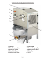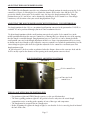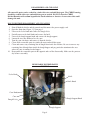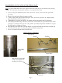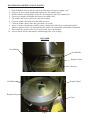
1
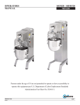
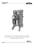
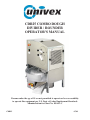
CDR25 COMBO DOUGH
DIVIDER / ROUNDER
OPERATOR'S MANUAL
Persons under the age of 18 are not permitted to operate or have accessibility
to operate this equipment per U.S. Dept. of Labor Employment Standards
Administration fact sheet No. ESA91-3.
CDR25
07/09
IMPORTANT SAFETY NOTICE
To insure both safe and trouble-free performance, we stress that all
personnel that will be involved with your new Univex CDR25 must
read and understand these instructions before attempting to operate
this unit.
FOR WARRANTY SERVICE
Contact the Univex warranty service department at (800) 258-6358
to report warranty claims before arranging repair or attempting to return the unit to Univex Corporation.
FOR SERVICE OUT OF WARRANTY
You can either:
1)
Visit our website at www.univexcorp.com for a list of
authorized service providers. (Click on authorized service
agents).
2)
Call Univex Corporation at (800) 258-6358 and ask for
contact information for your local service company.
TABLE OF CONTENTS
Description
Page
Introduction............................................................................................................................................2
Important Safety Warnings ....................................................................................................................2
Installation..............................................................................................................................................3
Operating Instructions............................................................................................................................4
Adjusting Dough Portion Size ...............................................................................................................5
Divider Disassembly and Cleaning ....................................................................................................6-7
Disassembly and Cleaning of the Small Portion Converter Head .........................................................8
Rounder Disassembly and Cleaning ......................................................................................................9
Warranty................................................................................................................................Back Cover
LIST OF ILLUSTRATIONS
Illustration
Figure
Figure
Figure
Figure
Figure
Figure
Figure
Figure
1
2
3
4
5
6
7
8
Page
Overall View of the CDR25 Divider / Rounder................................................................1
Rounder Start/Stop and Emergency Stop Switches ..........................................................4
Divider Start/Stop and Emergency Stop Switches............................................................4
Dough Portion Adjusting Controls ...................................................................................5
Removable Divider Parts ..................................................................................................6
Spiral Shaft Assembly.......................................................................................................7
Small Portion Converter Head Assembly .........................................................................8
Rounder.............................................................................................................................9
1
OVERALL VIEW OF THE CDR25 DIVIDER/ROUNDER
FIGURE 1
2
3
4
5
6
9
7
8
10
1. Top Cover
6. Feeler Control
2. Divider Emergency Stop
7. Rounder Emergency Stop
3. Divider ON 1st Speed
8. Rounder ON/OFF Switch
4. Divider ON 2nd Speed
9. Divider Door
5. Converter Head Control
10. Chute
Page 1
INTRODUCTION
This manual contains comprehensive instructions for the installation, operation and care of the
CDR25 dough divider/rounder. Disassembly, repair, replacement and reassembly instructions are
included. A complete replacement parts list with identifying figures is also included to facilitate
identification and ordering of replacement parts.
The CDR25 has been designed and manufactured to make pizza dough portions and to round them (at
room temperature). It eliminates tedious manual weighing and shaping of the dough.
Warning: Do not use frozen or semi-frozen dough in this machine.
IMPORTANT SAFETY WARNINGS
To Avoid Serious Injury:
• It is a violation of United States Department of Labor regulations to permit persons under the age
of 18 years to operate the CDR25 Divider/Rounder.
• Never operate or attempt to operate the CDR25 Divider/Rounder without training.
• Read and understand the instructions in this manual Before attempting to operate this CDR25
Divider/Rounder.
• Always keep your hands and fingers clear of the knife and all moving parts.
• Only install the CDR25 Divider/Rounder on a level nonskid surface in a clean, well-lit work area.
• Before cleaning, servicing or removing any parts, always turn the CDR25 Divider/Rounder off
and disconnect the electrical power supply cord.
• Follow the cleaning instructions for best results and for safety. Always turn the CDR25
Divider/Rounder off and disconnect the electrical power supply cord.
Page 2
INSTALLATION
INSPECTION
All CDR25 Divider/Rounder units are inspected and tested at the factory; however, they should be
inspected carefully by the person making the installation for loose, damaged, or broken parts. Detached
parts and fixtures should be checked against the packing list to determine that all parts are present. Any
damage, imperfections or shortages should be reported to the dealer or to Univex Corporation and the
shipping carrier.
Warning: After the CDR25 Divider/Rounder has been inspected, wash all removable parts completely
with warm water and mild soap. For safety, follow the cleaning instructions on page 6.
PACKAGING
The CDR25 Divider/Rounder is packed in a cardboard box, which is attached to a wooden pallet. Each
box contains a complete CDR25 Divider/Rounder. Take care when removing the CDR25
Divider/Rounder from the box, paying special attention to the cover and movable doors to avoid
damaging them.
INSTALLATION
The most efficient installation of your Univex CDR25 Divider/Rounder will depend on the layout of
your kitchen. Locate your CDR25 Divider/Rounder where it will save steps for the operator and be sure
to provide sufficient clearance around it for ease of maintenance and cleaning, as well as for efficient
and safe use.
The CDR25 Divider/Rounder should be operated on a sturdy bench, table or stand that is level. The
height of the bench, table or stand should be chosen for the maximum comfort and safety of the operator.
Many users have found a table height of 22 inches to be satisfactory. Be sure to fix the machine to the
bench, table or stand in order to avoid any possibility of the machine falling.
Place the machine far from any heat sources and take care to leave sufficient space near the motor
ventilation openings.
IMPORTANT
Warning/Caution: Electrical wiring diagrams are provided on page . Before making electrical
connections, CHECK the specifications on the nameplate, on the back panel of the machine, to make
sure they agree with those on your electrical service. If you do not have a mating receptacle, have a
qualified electrician provide one with grounding provisions in accordance with local safety codes.
Page 3
OPERATING INSTRUCTIONS
BEFORE OPERATING
• Be sure the side chute (Figure 1 [10] ) on the rounder is correctly installed.
• Check that all knobs on the unit are tight (auger, cone, knife,and rounder bell).
• Check that the rounder is correctly under the divider and that the switch is in contact. The unit will
not run if this switch is not closed.
• Check that the top and front covers on the divider are closed. The unit will not run with ether of
these doors open.
• Start the machine without dough in the hopper and check that the machine is working properly.
STARTING AND STOPPING THE ROUNDER
• Start the rounder by turning the switch (Figure 2) to the ON (I) position.
• To stop the rounder, turn the switch (Figure 2) to the OFF (O) position.
• There is an emergency stop push button (Figure 2), pushing this button will immediately stop the
rounder. To release the emergency stop, turn the knob counter-clockwise.
ROUNDER START/STOP AND EMERGENCY STOP SWITCHES
FIGURE 2
Rounder emergency
stop switch
Rounder start/stop
switch
STARTING AND STOPPING THE DIVIDER
• To start the divider, push one of the start buttons (Figure 3).
Speed 1 (I) is used for all types of dough
Speed 2 (II) is used for soft dough (generally a dough with a 55% or greater absorption ratio).
• To stop the divider, press the red STOP button (Figure 3) between the two start buttons.
• There is an emergency stop push button (Figure 3), pushing this button will immediately stop the
divider. To release the emergency stop, turn the knob counter-clockwise.
DIVIDER START/STOP AND EMERGENCY STOP SWITCHES
FIGURE 3
Divider emergency stop switch
Divider speed 1 start button
Divider speed 2 start button
Page 4
ADJUSTING THE DOUGH PORTION SIZE:
The CDR25 Divider/Rounder provides easy adjustment of dough portions by simply moving the feeler
control lever (Figure 4). Moving the lever adjusts the distance between the cone and the feeler. The
greater the distance between the feeler and the cone, the larger the dough portion will be. Dough
portions between 10½ and 26 oz. can be obtained by adjusting the feeler control lever. Your dough
consistency will determine what your actual dough portions weigh.
ADJUSTING THE DOUGH PORTION SIZE WITH THE SMALL CONVERTER HEAD:
For dough portions below 10½ oz., an optional small portion converter head (part number 3110545) is
available. It can be purchased through your local Univex authorized dealer.
To adjust dough portions with the small portion converter head, put the feeler control lever in the
middle position and adjust the converter control lever. Moving this lever adjusts the size of the opening
that the dough is extruded through. Dough portions between 3 and 10½ oz can be obtained with the
small portion converter head through adjustment of this lever. Some experimentation will be necessary
to obtain your desired dough weight. Adjust the converter control lever to find the position that gives the
closest dough weight to your desired weight then adjust the feeler control lever to obtain your exact
dough portion weight.
In general practice, the best results are obtained when the distance between the converter head and the
feeler is nearly equal to the diameter of the opening in the small portion converter head.
DOUGH PORTION ADJUSTING CONTROLS
FIGURE 4
Feeler control lever
Converter head
control lever
TIPS ON ADJUSTING DOUGH PORTION SIZE:
• For portion weights and CDR25 dough capacity, see the specification sheet.
• The data regarding portion weights are for general reference only since the actual dough
composition varies according to the quantity of water, flour type and temperature.
• The dough must be prepared first in a dough mixer.
• Before beginning to regulate the dough weight, be sure that the feeler is correctly placed in front of
the hole in the cone.
Page 5
DISASSEMBLY AND CLEANING
All removable parts can be washed in a sink with water and mild detergent. The CDR25 housing
should be washed with water and mild detergent as needed. DO NOT clean the CDR25
Divider/Rounder with sodium hypochlorite based solutions or abrasive cleaners since this could
damage the unit.
DOUGH DIVIDER DISASSEMBLY AND CLEANING:
1.
2.
3.
4.
5.
6.
7.
8.
9.
Shut off both the divider and the rounder and disconnect the power supply cord.
Open the front door (Figure 1 [9]) on page 1.
Unscrew the feeler knob and remove the dough feeler.
Partially unscrew the knife knob and remove the knife.
Unscrew the dough support knob and remove the dough support.
Loosen the two cone knobs to free the cone.
Turn the cone clockwise and remove it from the divider.
Clean all the removable parts in a sink with water and mild detergent.
Clean and remove any remaining bits of dough from inside the machine. Be sure to remove any
remaining bits of dough from inside the dough hopper and pay particular attention to the area
where the cone is mounted to the hopper.
10. Reassemble the removable parts in the opposite order of the disassembly. Make sure the parts are
dry before reassembly.
REMOVABLE DIVIDER PARTS
FIGURE 5
Feeler Knob
Knife
Knife Knob
Cone Knob
Cone
Dough Support Knob
Dough Feeler
Dough Support
Page 6
DISASSEMBLY AND CLEANING OF THE SPIRAL SHAFT:
Note: The spiral shaft should be removed and cleaned at the same time the rest of the divider is being
cleaned. The instructions for the spiral shaft have been separated for clarity.
1. Unscrew the spiral shaft knob, (on the back panel of the divider), and remove the spiral shaft
assembly.
2. Remove the spiral shaft from the spiral assembly.
3. Clean the parts with water and mild detergent. Take special care to remove any dough remains
from the pin holes and the bearing area.
4. Thoroughly dry all parts and lubricate the bushing on the spiral with Petrol-Gel lubricant.
5. After drying and lubricating, install the spiral in the divider. Rotate the spiral until the holes in the
spiral line-up with the pins in the drive and push the spiral fully into position. NOTE the two pins
are different sizes 10mm and 12mm.
6. Reinstall the spiral shaft into the divider. Rotate the spiral shaft until the flats on the shaft line-up
with the slot in the drive assembly and push the shaft fully into position.
7. Screw the spiral shaft knob on to the spiral shaft.
SPIRAL SHAFT ASSEMBLY
FIGURE 6
Spiral
Bushing
Spiral Shaft
Knob
Spiral Shaft
Make sure the spiral shaft
is fully seated against the
bushing in the spiral.
Align pins
Page 7
DISASSEMBLY AND CLEANING OF THE SMALL PORTION CONVERTER HEAD:
1.
2.
3.
4.
5.
6.
7.
8.
9.
10.
Follow the divider disassembly instructions 1-6 on page6.
Remove the converter head drive link from the adjusting lever mechanism.
Loosen the two converter mounting knobs to free the converter head assembly.
Rotate the converter head clockwise off the mounting studs and remove it from the divider.
Unscrew the two flange retaining knobs on the converter head and remove the flange from the
cone assembly.
Remove the four plastic restrictor blocks from the cone.
Wash all Parts with water and mild detergent.
To reassemble the converter head, place the cone on a bench with the studs facing up.
Place the restrictor blocks on the cone with the dogs in the groove on the cone flange and the
radius facing the hole in the cone.
Place the flange on the cone assembly with the pins in the restrictor blocks in the slots in the flange
and reinstall and tighten the knobs.
SMALL PORTION CONVERTER HEAD
FIGURE 7
Drive Link
Flange retaining
Knobs
Radius
Converter Head
Mounting Knobs
Flange
Dog
Restrictors
Slot
Stud
Pin
Page 8
ROUNDER DISASSEMBLY AND CLEANING:
1.
2.
3.
4.
5.
6.
7.
8.
Shut off both the divider and the rounder and disconnect the power supply cord.
Unscrew the two rounder guard knobs and remove the rounder guard.
Pull the rounder out from under the divider far enough to remove the rounder bell.
Unscrew the rounder bell knobs and remove the rounder bell.
The rounder bell may be placed in a sink for cleaning.
Clean the rounder bell with water and mild detergent.
Clean the rounder bowl, chute and guard with a wet cloth.
Spray a commercial non-toxic sanitizer on the rounder bowl and bell as recommended on the
sanitizer container label. It is important that the sanitizer be compatible with anodized aluminum.
9. Reassemble the rounder in the reverse order of the above disassembly.
10. Always run the divider and rounder without dough after each cleaning.
ROUNDER
FIGURE 8
Guard Knobs
Guard Knobs
Rounder Guard
Rounder
Bell Knobs
Rounder Bowl
Rounder Bell
Chute
Page 9
WARRANTY
The Univex CDR25 Divider/Rounder carries a one-year, on-site parts
and labor warranty against any defects in materials or workmanship.
The one-year period begins on the date of purchase by the end user and
remains in full effect provided the unit is used properly in accordance
with our instructions. Any work to be preformed under this warranty
must be preformed between the hours of 8:00 a.m. and 5:00 p.m. local
time, Monday through Friday. Univex will not cover overtime charges
of any kind. Please call the Univex Warranty Service Department at
(800) 258-6358 to report any warranty claims before arranging repair or
attempting to return the unit to Univex Corporation.
Damages incurred in transit or incurred because of installation error,
accident, alteration or misuse are not covered. Transit damages should
be reported to the carrier immediately.
Univex will not be liable for any consequential, compensatory,
incidental or special damages.
3 Old Rockingham Road Salem, N.H. 03079 Tel: (800) 258-6358 Fax: (800) 356-5614
Int’l Tel: (603) 893-6191 Int’l Fax: (603) 893-1249 Web: www.univexcorp.com
Email: [email protected]