1
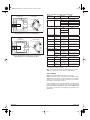
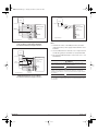
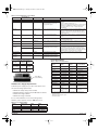
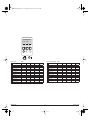
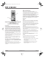
MN03902004E.fm Page 1 Tuesday, November 28, 2006 8:49 AM
QCPort Communications
QCPort is a protocol developed to provide
communications between Eaton’s Cutler-Hammer IT.
control products and does not need to be set up for basic
local operation of the S811 Soft Starter. The RJ12
connectors (Chan 0, Chan 1) and the 8-position DIP switch
located on the front cover relate to the QCPort
communication setup. QCPort application and setup
information is not covered in this publication. Contact your
local Eaton representative or see the QCPort System Install
Manual, Pub. No. MN05001002E for more information.
DIM
Status LED
Inspection
Main TB
Cutler-Hammer Intelligent Technologies (IT.)
S811 Soft Starter
Installation and Setup Guide
Introduction
The Cutler-Hammer® Intelligent Technologies (IT.) Soft
Starter from Eaton’s electrical business is an electronic
self-contained, panel or enclosure mounted motor soft
starting device. It provides three-phase induction motors
with a smooth start, both mechanically and electrically.
The IT. line of soft starters utilizes six SCRs connected in a
full wave power bridge. The voltage and current applied to
the motor is controlled by varying the SCR conduction
period. This, in turn, controls the torque developed by the
motor. After the motor reaches speed, a bypass contactor
is energized to bypass the SCRs.
The IT. Soft Starter is designed to fulfill the industrial service
requirements of applications such as chiller starters, pump
panels and machine tools.
The IT. Soft Starter meets all relevant specifications set
forth by ICS-1, ICS-2, ICS-5, UL 508, IEC 60947-4-2, CSA
C22.2 No. 14 and CE.
This leaflet covers basic installation and setup. A
copy of the IT. S811 Soft Starter User Manual (Pub. No.
MN03902002E) is downloadable at www.EatonElectrical.com
or contact Eaton.
No publication can take into account every possible
situation. If you require further assistance with any aspect
of this product or a particular application, feel free to
contact us.
MN03902004E
General
Upon receipt of the unit, verify that the catalog number
and unit options stated on the shipping container match
those stated on the order/purchase form.
Inspect the equipment upon delivery. Report any carton
damage to the carrier prior to accepting the delivery. Have
this information noted on the freight bill. Eaton is not
responsible for damage incurred in shipping.
Unpacking
Remove all packing material from the unit. Be sure to
remove all packing material from lug location. Also, make
sure no packing material is left behind that would block the
airflow to the fan.
Check the unit for any signs of shipping damage. If
damage to the product is found after unpacking, report it
to the freight company. Retain the packing materials for
the carrier to review.
Verify that the unit’s catalog number and options match
those stated on the order/purchase form.
Storage
It is recommended that the unit be stored in its original
shipping box/crate until it is to be installed.
The unit should be stored in a location where:
•
•
•
•
The ambient temperature is between -58°F and 158°F
(-50°C and 70°C)
The relative humidity is between 0% and 95%,
non-condensing
The environment is dry, clean, and non-corrosive
The unit will not be subjected to high shock or
vibration conditions
www.EatonElectrical.com
November 2006
MN03902004E.fm Page 2 Tuesday, November 28, 2006 8:49 AM
1.97
(50.0)
2.66
(67.6)
6.47
(164.4)
15.16
(385.0)
Slots
5.35
(135.9)
7.38
(187.4)
6.87
(174.5)
3.46
(88.0)
.22 (5.5)
Typ. 4
Places
16.57
(420.8)
15.63
(397.0)
Figure 1: Model S811N (65 mm)
3.54
(90.0)
11.05
(280.6)
.26 (6.5) Dia.
Typ. 4 Places
Figure 5: Model S811V (290 mm)
1.83
(46.4)
1.77
(45.0)
5.53
(140.5)
7.44
(189.0)
.27 (6.7) Dia.
Typ. 4 Places
3.74
(95.0)
4.38
(111.3)
6.66
(169.2)
7.35
(186.6)
9.84 (250.0)
.91
(23.2)
.29
(7.5)
.89
(22.5)
3.49
(88.5)
2.91
(74.0)
.27 (6.8)
Typ.
4 Places
2.68
(68.0)
7.92
(201.2)
.31
(8.0)
Figure 2: Model S811R (110 mm)
Frame
Size in
In. (mm)
S811N
7.67
(194.8)
12.71
(322.9)
11.77
(299.0)
Slots
5.40
(137.2)
2.95
(75.0)
Slots
5.91
(150.0)
Slots
.28 (7.1)
Slots Typ.
6 Places
Washer
Size
Qty.
Req.
Torque
Req.
#10 – 32
x 0.5
Standard #10
Lockwasher & Flat
Washer
4
15 lb-in
(1.7 Nm)
5.8 (2.6)
1/4 – 20
x 0.625
Standard 1/4 in.
Lockwasher & Flat
Washer
4
25 lb-in
(2.8 Nm)
10.5 (4.8)
1/4 – 20
x 0.625
Standard 1/4 in.
Lockwasher & Flat
Washer
6
30 lb-in
(3.4 Nm)
48 (21.8) Quantity: 4
ID: 0.270
OD: 0.495 — 0.505
Max. 0.055 Thick
Quantity: 4
Special Washer
Included with V Frame Units
8
50 lb-in
(5.6 Nm)
103 (46.8) S811R
4.33
(110)
S811T, S811U
7.87
(200)
.47
(11.9)
S811V
11.42
(290)
5.20 (132.0)
C Mounting
L
Mounting
Slots for M6
(1/4) Screws
(Up to 6
Quantity)
5.20 (132.0)
Pole
Centers
C
L
1/4 – 20
x 1.5
Grade 8 Allen
head hex cap
screws
Weight with lugs. Weight without lugs is 41 (18.6).
Weight with lugs. Weight without lugs is 91 (41.4).
Table 2: Environmental Requirements
7.08
(179.9)
12.72
(323.1)
Weight of
Unit in
lb. (kg)
Screw
Size
2.55
(65)
Figure 3: Model S811T (200 mm)
11.77 (299.0)
Mounting
.41
(10.5)
.49
(12.5)
Figure 6: DIM Approximate Dimensions in Inches (mm)
Table 1: Mounting Hardware and Torque Specifications
6.39
(162.4)
7.73
(196.3)
Figure 4: Model S811U (200 mm)
MN03902004E
3.08
(78.3)
2
Operating Temperature Range
-40°F to 122°F (-40°C to 50°C)
DIM LCD -4°F to 158°F (-20°C to 70°C)
Storage Temperature Range
-58°F to 158°F (-50°C to 70°C)
DIM LCD -22°F to 176°F (-30°C to 80°C)
Elevation
Above 2000 meters consult factory
Humidity
Functional to 95% non-condensing
Operating Orientation
Any orientation in the vertical plane
Pollution Degree IEC 60947-1
3
Shock Resistance
15g in any direction
Vibration Resistance
3g in any direction
November 2006
MN03902004E.fm Page 3 Tuesday, November 28, 2006 8:49 AM
Mounting Instructions
Power Wiring
The IT. Soft Starter is easy to mount. It does not require
any special tools.
Using the wiring diagrams in Figures 7 – 10 and Table 3
below as guides, connect the Line, Motor, and Power
Supply wiring in accordance with appropriate local and
national codes. For more detailed information and special
applications refer to the IT. S811 Soft Starter User Manual
(Pub. No. MN03902002E).
To aid you with panel layout, refer to the dimension
drawings shown in Figures 1 through 5. Drill and tap holes
per mounting hole/slot locations as shown.
To mount the unit, use all the hardware specified in Table 1
of this leaflet. Tighten to the torque specified.
Note: To provide optimum motor protection the Line and
Motor power wiring should be tightly bundled and run
perpendicular to the orientation of the S811.
Danger High Voltage
Hazardous voltage can cause electric shock and burns. To avoid shock hazard,
disconnect all power to the controller, motor or other control devices before any
work is performed on this equipment. Failure to do so will result in personal
injury, death or substantial property damage.
Do not apply a disconnect device on the output of the IT. Soft Starter unless a
means to turn off the soft starter when disconnect switch is open is utilized.
Opening disconnect while the IT. Soft Starter is operating may cause a
malfunction. Closing disconnect switch while the IT. Soft Starter is operating will
result in a soft starter failure and potential equipment damage and personnel
hazard.
1 L1
3 L2
5 L3
S811
Danger Haute Tension
Une tension électrique dangereuse peut causer des chocs électriques et des
brûlures. Pour éviter des chocs électriques, débrancher l’alimentation du
contrôleur, du moteur ou des autres appareils de contrôle avant d’y effectuer du
travail. L’inobservation de ces instructions entraînera des blessures corporelles
graves, la mort ou des dégâts matériels substantiels.
Ne pas appliquer un appareil de sectionnement sur la sortie du démarreur
progressif IT. à moins qu’un moyen d’éteindre le démarreur progressif quand
l’interrupteur de sectionnement est ouvert soit utilisé. Le fait d’ouvrir
l’interrupteur de sectionnement pendant le fonctionnement du démarreur
progressif IT. peut entraîner une défaillance. Le fait d’éteindre l’interrupteur de
sectionnement pendant le fonctionnement du démarreur progressif IT.
entraînera la défaillance du démarreur progressif et des dégâts à l’équipement
ou risque au personnel.
2 T1
4 T2
6 T3
M
3
˜
Figure 7: Line Connected Soft Starter Power Wiring Diagram
Peligro alto voltaje
Supply
L1S L2S L3S
Voltajes peligrosos que pueden causar descargas eléctricas y quemaduras. Para
evitar descargas eléctricas, desconecte la alimentación del controlador, del
motor u otros dispositivos de control antes de efectuar cualquier trabajo en el
equipo. El incumplimiento de estas medidas ocasionará lesiones personales, la
muerte o daños importantes al material.
No aplique un dispositivo de desconexión a la salida del arrancador IT. Soft
Starter a menos que se utilice un medio para apagar el arrancador cuando el
interruptor de desconexión está abierto. La apertura del interruptor de
desconexión mientras el arrancador IT. está operando puede ocasionar un
funcionamiento incorrecto. El cierre del interruptor de desconexión mientras el
arrancador IT. está operando producirá una falla de dicho arrancador, como
también potenciales daños a los equipos y riesgo para el personal.
L3
1 3 5
L1 L2 L3
T5
T2
T5 T4 T6
S811
Motor
L2
L2
T4
2 4 6
T1 T2 T3
L3
T2
T3
T3
T1
T6
T1
T3 T2 T1
L1
L1
Figure 8: Inside-the-Delta Connected Soft Starter
Power Wiring Diagram for a 6-Lead Motor
MN03902004E
3
November 2006
MN03902004E.fm Page 4 Tuesday, November 28, 2006 8:49 AM
Table 3: Power Wire Sizing and Torque Requirements
12-Lead
Low Voltage
Supply
L1S L2S L3S
L3
L3
T11 T10 T12
T5 T4 T6
1 3 5
L1 L2 L3
Motor
S811
2 4 6
T1 T2 T3
T3 T2 T1
T9 T8 T7
Number of
Conductors
T11
T8 T5
T2
L2
T2
L2
T4
T10
T1
T7
L1
Lug Type
Wire Sizes
Cu 75°C Only
Torque
Requirements
2 AWG
50 lb-in (5.6 Nm)
Frame Size — N
1
Box Lug
T3
T3 T9
T6 T12
4 – 6 AWG
45 lb-in (5.0 Nm)
8 AWG
40 lb-in (4.5 Nm)
10 –14 AWG
35 lb-in (4.0 Nm)
14 – 8 AWG
(2.5 – 10 mm2)
90 – 100 lb-in
(10.1 – 11.3 Nm)
Frame Size — R
1
Box Lug
T1
L1
6 – 4 AWG
(16 – 25 mm2)
3 – 3/0 AWG
(27 – 95 mm2)
Figure 9: Inside-the-Delta Connected Soft Starter Power
Wiring Diagram for a 12-Lead Low Voltage Motor
Frame Size — T (see Note)
12-Lead
High Voltage
Supply
L1S L2S L3S
L3
T11 T10 T12
1 3 5
L1 L2 L3
S811
2 4 6
T1 T2 T3
Motor
T8 T7 T6
T5 T4 T9
L2
T3 T2 T1
L1
L2
T11
T8
T5
T2
T2
T10
T7
T4
T1
T1
L3
T3
T3
T6
T9
2
(2) EML22
4 – 1/0 MCM
(21.2 – 53.5 mm2)
250 Lb-in (28.3 N•m)
1
(2) EML23
4/0 – 500 MCM
(107 – 240 mm2)
250 Lb-in (28.3 N•m)
2
(2) EML24
4/0 – 500 MCM
(107 – 240 mm2)
250 Lb-in (28.3 N•m)
1
(2) EML25
2/0 – 300 MCM
(70 – 150 mm2)
225 Lb-in (25.5 N•m)
2
(2) EML26
2/0 – 300 MCM
(70 – 150 mm2)
225 Lb-in (25.5 N•m)
(2) EML24
4/0 – 500 MCM
(107 – 240 mm2)
250 Lb-in (28.3 N•m)
(2) EML26
2/0 – 300 MCM
(70 – 150 mm2)
225 Lb-in (25.5 N•m)
Frame Size — U (see Note)
T12
2
L1
Frame Size — V (see Note)
Figure 10: Inside-the-Delta Connected Soft Starter Power
Wiring Diagram for a 12-Lead High Voltage Motor
2
(2) EML28
4/0 – 500 MCM
(107 – 240 mm2)
250 Lb-in (28.3 N•m)
4
(2) EML30
4/0 – 500 MCM
(107 – 240 mm2)
250 Lb-in (28.3 N•m)
6
(2) EML32
4/0 – 500 MCM
(107 – 240 mm2)
250 Lb-in (28.3 N•m)
(2) EML33
2/0
(70
– 300 MCM2
– 150 mm )
225 Lb-in (25.5 N•m)
4
Requires special lug cover. Check with Eaton for availablility.
CSA approved 350 MCM – 500 MCM.
Note: For T, U and V frames, optional lug kits are shown
(EML**) and may be required for your installation.
Control Wiring
Figures 11, 12 and 13 illustrate typical connection
diagrams for the control circuit options described. In these
diagrams the soft starter is represented by the removable
wiring connector. All other items shown are not included
but may be purchased from Eaton.
Control wiring is connected to the IT. S811 Soft Starter by a
12-pin terminal block located at the front of the unit. Using
the wiring diagrams in Figures 11, 12 and 13 and Tables 4 and
5 as guides, connect the control wiring as required for your
application.
MN03902004E
4
November 2006
MN03902004E.fm Page 5 Tuesday, November 28, 2006 8:49 AM
Power Supply
Power Supply
24V DC
+
24V DC
–
+
(See Note 1)
–
+
* E-Stop
Stop
Start
Jumper
+24V to 3
Jog
Reset
In Bypass
Ready
Fault
*
24V DC Power
P
1
2
3
4
13
14
95
96
98
(See Note 3)
–
+
* E-Stop
S811 Soft Starter
P
1
2
3
4
13
14
95
96
98
Jumper
+24V to P
Inputs
24V DC Only
Internal
Contacts
*
Optional 24V DC
Pilot Lights
(See Note 2)
E-Stop Maintained
–
(See Note 1)
E-Stop Maintained
24V DC Power
S811 Soft Starter
Inputs
24V DC Only
Internal
Contacts
Figure 13: Basic Connection Diagram for Use of DIM Control Only
Figure 11: Basic Connection Diagram for 24V DC
3-Wire Pushbutton STOP/START/JOG/RESET
and 24V DC Fault/Ready and Bypass Indication
Note:
1. A minimum of wire of 14 AWG (2.5 mm2) should be
used between the power supply and the 24V DC + and terminals.
Power Supply
2. See User Manual if it is desired to use a relay instead of
an indicating lamp for terminals 13, 14, 95, 96 and 98.
24V DC
+
–
(See Note 1)
* E-Stop
Jumper
+24V to 3
Jumper
Hand
OFF
Auto
Remote
(See Note 3) Contact
Reset
In Bypass
Ready
Fault
*
E-Stop Maintained
–
+
P
1
2
3
4
13
14
95
96
98
3. The start input TB #1 default is set for level sense – See
User Manual.
24V DC Power
S811 Soft Starter
Caution
Inputs
24V DC Only
Only apply 24V DC to the terminal block unless specified otherwise in this
manual. All control wiring is 22 – 12 AWG (0.33 – 2.5 mm2). Failure to follow this
caution could result in severe damage to the controller.
Internal
Contacts
Attention
Appliquer seulement 24V CC à la barrette à bornes sauf ce manuel offre d’avis
contraire. Tout le câblage de commande est de calibre 0,33 – 2,5 mm 2 (22 –
12 AWG). L’inobservation de cet énoncé pourrait entraîner des dégâts matériels
au contrôleur.
Optional 24V DC
Pilot Lights
(See Note 2)
Precaución
Figure 12: Basic Connection Diagram for 24V DC 2-Wire Switch
HAND/OFF/AUTO(Remote Contact)/RESET
and 24V DC Fault/Ready and Bypass Indication
MN03902004E
Aplique sólo 24 V CC al bloque de terminales, a menos que se especifique lo
contrario en este manual. Todo el cableado de control es de 0.33 – 2.5 mm 2
(22 – 12 AWG). Si no respeta esta precaución, se pueden producir daños graves
al controlador.
5
November 2006
MN03902004E.fm Page 6 Tuesday, November 28, 2006 8:49 AM
Table 4: S811 Terminal Block Control Wiring
Name
Terminal Block
Designation (Pin)
Factory Default
Input
Connections
Circuit Common
-
—
Negative
Power
+
—
24V DC nominal (see 24V DC Power
Supply Requirements section for
sizing of power supply)
Power supply connections:
– Connect power supply negative to pin “–” and to system
ground
– Connect +24V DC output to pin “+”
Note: To avoid voltage drop during bypass contactor inrush,
a minimum of 14 AWG wire should be used between the
power supply and the “+” and “–” inputs at the S811
terminal block.
Permissive
P
Hardwired STOP
24V DC only (maintained input)
Pin “P”, permissive, must be energized (+24V DC) to enable
operation of the unit. If power is removed from the
permissive circuit at any time, the unit will begin a STOP
command. If a soft stop is selected, the soft stop will begin
and run to time-out.
Input 1
1
START
24V DC only (momentary input)
Applying 24V DC to Input 1 while P is energized will initiate a
START. As shipped from the factory this input is “level”
sensitive.
Input 2
2
JOG
24V DC only (momentary input)
Input 2 is JOG. Applying 24V DC to this input while P is
energized will initiate a JOG.
Input 3
3
HAND/AUTO
24V DC only Must be maintained for
control from the terminal block
Input 3 is HAND. Hand must be energized to enable control
(START/JOG) through the terminal block.
Input 4
4
Fault RESET
24V DC only
Input 4 is Fault RESET. Energizing this input will reset a fault
only after the fault condition has been corrected.
Relay1 Form A
NO Contact
13
Common
14
NO De-energized
3 Amps, @ 230V AC/24V DC,
3 Amps, Max (Resistive) Switching
NO Form A contact: As shipped from the factory this
programmable contact closes when the starter’s bypass
contactor is energized. It will remain closed until a STOP is
initiated. The motor may continue to run even after the STOP
is initiated until the stop ramp has been completed.
Form C Common
95
Common
Form C Common for 96 and 98
Relay2 Form C
NC Contact
96
NC De-energized
3 Amps, @ 230V AC/24V DC,
3 Amps, Max (Resistive) Switching
Form C contacts: As shipped from the factory these
programmable contacts will change status when a Fault
occurs.
Relay2 Form C
NO Contact
98
NO De-energized
3 Amps, @ 230V AC/24V DC,
3 Amps, Max (Resistive) Switching
Protective Features
Table 5: Terminal Block Specifications
Wire Size
Number of
Conductors
Torque
22 – 14 AWG
2
(0.33 – 2.5 mm2)
3.5 lb-in
(0.4 Nm)
12 AWG
(4.0 mm2)
3.5 lb-in
(0.4 Nm)
1
Table 7: S811 Protective Features 12 Pin TB for
Control Wiring
Protective
Feature
Setting
Factory
Default
(Protections Menu)
Parameter
Overload
32 – 100% 32%
Overld Trip FLA
Trip Class
5, 10, 20 and 30
20
Ovrld Trip Class
Overload
Enable, Disable Enabled
Overload Fault
Auto Reset
Manual, Auto
Manual
Reset Mode
Jam
Enable, Disable
Enabled
Jam Fault
Stall
Enable, Disable
Enabled
Stall Fault
Phase Loss
Enable, Disable
Enabled
Phase Loss Fault
Phase Rev Fault
Phase Reversal
Enable, Disable
Enabled, ABC
Phase Imbalance
Enable, Disable
Enabled
Phase Imb Fault
Undercurrent
1 – 100% FLA
6% FLA
Lo I Trip % FLA
Rated Voltage
115 – 690V
480V
—
24V DC Power Supply Requirements
Undervoltage
Enabled, 90%
A 24V DC power supply for your S811 Soft Starter must
meet the following requirements:
Enable, Disable
1 – 99% rated
voltage Lo Volt Trip
Lo Volt Level
Overvoltage
Enable, Disable
101 – 120% rated
voltage
Enabled, 110%
Hi Volt Trip
Hi Volt Level
•
•
•
•
Minimum steady state power: 25 watts
Minimum bypass contactor inrush: 240 watts for 150 mS
Maximum voltage: 30V DC
Minimum voltage: 19.2V DC
See S811 User Manual (Pub. No. MN03902002E) for a complete list of
protective features.
Of rated current.
Disabled until next power cycle.
80V AC fixed trip.
It is recommended that one of the following CutlerHammer power supplies shown in Table 6 be used.
Table 6: Power Supply Ratings
Catalog
Number
Steady State
Wattage
Surge
Wattage
Input
Voltage
PSS55A
55W
250W
115V AC
PSS55B
55W
250W
230V AC
PSS55C
55W
250W
360 – 480V AC
MN03902004E
6
November 2006
MN03902004E.fm Page 7 Tuesday, November 28, 2006 8:49 AM
Programming the S811
Soft Starter Operating Modes
A Digital Interface Module (DIM) is used to program all
models of the IT. S811 Soft Starter.
The IT. S811 Soft Starter will start a motor and its load in
one of two modes, Voltage Ramp or Current Limit. The
mode is set by the Start Method parameter.
Using the DIM
Referring to Figures 14 and 15 —
• The Status Bar at the top of the display indicates the
operating and communicating status of the S811 and DIM.
• The three Soft Key Functions at the bottom of the
display indicate the functions of the Soft Keys
(pushbuttons) directly below them. The Soft Key
Functions will change as you navigate through the
different menus of the DIM.
• The center of the display shows the value of the
selected S811 parameter. The default display at
power-up is “3 ø Line Currents”.
• Pages 14 – 21 show how the S811’s parameters are
organized within the menu structure. Navigating
through the menus down to the parameters is
straightforward if you understand a few basic
concepts.
1. The Escape Key (ESC) moves you from the User
Display to the Parameter Edit Screen.
2. The PREV and NEXT soft keys (Figure 15) scroll
from menu to menu (left and right).
3. The far right soft key will allow you to take action
(Enter, Edit, More, Send, …) to “drill down” into
the menu or parameter.
4. When you enter a menu, the Previous and Next
soft keys scroll from parameter to parameter (up
and down) in that menu.
5. The Escape Key backs you out of the current
parameter or menu.
For further information on the operation, including access
levels of the DIM, refer to the IT. S811 Soft Starter User
Manual (Pub. No. MN03902002E) available at the Eaton
Electrical Web Site www.EatonElectrical.com.
Voltage Ramp Start
Starting at an initial value set by the Initial Torque
parameter, the voltage applied to the motor is gradually
increased at a rate that will reach rated voltage at the time
set by the Soft Start Time parameter. As the voltage
increases, the motor develops torque that accelerates the
load. When the S811 senses that the motor is up to speed,
it quickly completes the voltage ramp and closes the
bypass contactor.
It should be noted that a lightly loaded motor takes less
torque, and thus lower voltage and time, to accelerate to
full speed. For this case the S811 will go into bypass before
the ramp reaches full voltage. In other words, the S811
may go into bypass before the Soft Start Time has elapsed.
Bypass
Torque
Voltage
Ramp
Kick
Start
Torq
Initial
Torque
Rated
Voltage
100%
Soft Start Time
Kick Start Time
Start
Run
Time (Seconds)
Bypass
100%
JOG
RESET
H->A
Status Bar
Speed
ONLN SS OXFDO1 H STOP
3 Line Currents
XXXX
L1 Amp
XXXX
L1 Amp
XXXX
L1 Amp
Soft Key Functions
Soft Keys
Predefined Keys
ESC
Start
Run
Time (Seconds)
Figure 14: Digital Interface Module (DIM) — Display Mode
Figure 16: Ramp Start
ONLN SS OXFDO1 H STOP
Current Limit Start
During a Current Limit Start the S811 applies a constant
voltage to the motor, resulting in limited current flowing
through the motor’s windings. This mode is typically used
when it is necessary to limit current during start due to line
power limitations or other considerations. The level of
current is set by the Initial Torque parameter.
Status Bar
Monitoring
PREV
NEXT
ENTER
Soft Key Functions
Soft Keys
Predefined Keys
Note: Current Limit Starts are not recommended on
variable torque load applications such as fans and pumps.
ESC
Figure 15: Digital Interface Module (DIM) — Parameter Edit Mode
MN03902004E
7
November 2006
MN03902004E.fm Page 8 Tuesday, November 28, 2006 8:49 AM
IMPORTANT:
Note the following items before you begin.
Bypass
Kick
Start
Torq
1. P and Hand inputs must be energized (24V DC) to
enable starting of the soft starter from the terminal
block.
2. To Start: Apply 24V DC to Input 1 while the P input is
energized.
3. To initiate a Stop, remove the P input.
4. For 2-wire control, jumper P and Input 1 together.
5. After an Overload Trip, the S811 Soft Starter cannot
be restarted until the prescribed cool-down time
has elapsed. Cycling power does not reset the timer.
If 24V DC power is removed, the soft starter will
remember the remaining time and will resume the
cool-down timing when power is again applied.
6. On Frames R, T, U and V when the S811 goes into
bypass, a sound similar to contactor chatter can be
heard. This sound is the result of multiple contactors
closing one after the other in a very short period. It is
normal operation intended to reduce the surge
current requirements of your power supply.
Current
Initial
Torque
100%
Soft Start Time
Kick Start Time
Start
Run
Time (Seconds)
Bypass
Speed
100%
Danger
The S811 has the ability to respond to commands from an automated network
controller. Consequently the soft starter may start unexpectedly in response to
these commands. To insure the safety of personnel and equipment, always
remove power before accessing the electrical and/or mechanical equipment.
Danger
Start
Le S811 à la capacité de répondre aux commandes d’un contrôleur de réseau
automatisé. Donc le démarreur progressif peut démarrer soudainement en
réponse à ces commandes. Pour s’assurer la sécurité du personnel et de
l’équipement, toujours débrancher l’alimentation avant d’accéder à l’équipement
électrique et/ou mécanique.
Run
Time (Seconds)
Peligro
Figure 17: Current Limit Start
El S811 tiene la capacidad de responder a comandos de un controlador de red
automatizado. Por lo tanto, el arrancador suave podría arrancar de improviso en
respuesta a estos comandos. Para garantizar la seguridad del personal y del
equipo, siempre desconecte la energía antes de acceder al equipo eléctrico o
mecánico.
Kick Start — This feature provides an initial boost in
torque to overcome the initial static friction in some
applications. The level of torque boost is set by the Kick
Start Torq parameter and the duration of the “kick” is set
by the Kick Start Time. Setting the Kick Start Time to 0
disables this feature.
Quick Setup
Configuring the S811 Soft Starter
After all power and control connections have been made
and you have read and understood the different operating
modes of the soft starter, it is time to program it for your
application. As shipped from the factory, the S811 Soft
Starter’s default configuration is sufficient for basic
operation but may require some configuration to “tune” it
for your application. The following basic setup procedure
assumes you understand how to navigate through the
S811’s parameter menu using the Digital Interface Module
(DIM) and that the S811 is in its Factory (Out-of-Box) state.
Refer to the S811 User Manual (Pub. No. MN03902002E),
Chapter 8, for a detailed explanation of the DIM.
Soft Stop — This feature is used for applications that
require a controlled extended stop. It is designed for high
frictional loads that tend to stop suddenly when voltage to
the motor is removed.
Note: This function will not stop the motor any faster than
it would normally take to coast to a stop under load.
Coast to Stop
(Speed)
100%
Speed
Soft Stop Ramp
(Voltage)
Soft
Stop Time
Run
Soft Stop
Time (Seconds)
Figure 18: Soft Stop
MN03902004E
8
November 2006
MN03902004E.fm Page 9 Tuesday, November 28, 2006 8:49 AM
Advanced Setup
Initial Configuration
For proper operation of the S811, these settings must be
set prior to use:
1. It is suggested that the S811 Soft Starter be
configured before applying the line voltage. Apply
24V DC to the (+) and (-) connections of the S811
terminal block. “Eaton Cutler-Hammer” will be
displayed by the DIM while the S811 is powering up.
When power-up is complete the DIM should display
“3 ø Line Currents”.
Note: If anything else is displayed, go to Chapter 8 of
the S811 User Manual, Troubleshooting, for information
on getting the S811 back to a known state.
If Stall faults occur or satisfactory operation is not
achieved with the quick setup in the previous section, the
problem is most likely related to the torque or time
settings. The following procedures using the Soft Start
Confg menu are suggested as alternatives.
Voltage Ramp Start Configuration
1. Initial parameter settings:
• Start Method = Voltage Ramp
• Initial Torque = 50%
• Soft Start Time = 60 sec
• Kick Start Torq = 0% (fans and pumps), 75% (high
breakaway loads)
• Kick Start Time = 0 sec (fans and pumps), 1 sec
(high breakaway loads)
• Soft Stop Time = 60 sec
2. Start the motor and determine the worst case starting
conditions. Adjust Initial Torque for smooth start
without hesitation. Rotation should begin within 2
seconds.
3. If Stall Faults occur at the end of the ramp time,
increase Initial Torque, Kick Start Torq & Time and/or
Soft Start Time to get into bypass before the Soft Start
Time elapses. Also, verify that the motor is not
overloaded.
4. Adjust the Soft Stop Time for the desired stopping
time.
2. Using the DIM, review the parameter settings in the
“Soft Start Confg”, “Overload Config” and
“Protection Setup” menus. The following setup
procedures will use the factory default settings unless
changed by you.
Note: Refer to the Menu structure shown on Pages 10 – 13
for the location and more information on the parameters
referenced in this setup.
3. In the Overload Config menu set the Overld Trip FLA
parameter to the motor’s nameplate rated current. This
setting assumes the motor has a 1.15 Service Factor.
4. Set Ovrld Trip Class parameter for the desired
overload trip characteristic (curve).
5. In the Protection Setup menu set the Motor Rated Volt
parameter to the motor’s operating voltage.
6. If auto fault reset is required, set the Reset Mode
parameter in the Soft Start Confg menu to Auto (and
Start Control to Level (default)). Note: Auto Reset is
intended for unattended installations where there is
no danger to personnel or other equipment when the
motor starts without warning. If Auto Reset is
enabled, CAUTION must be exercised to assure that
any restart occurs in a safe manner.
7. Apply the Mains voltage and verify that no fault is
present. If a fault is indicated, display the Diaignostic
menu’s Device Status parameter to determine the
source of the fault. Each fault is described in the S811
User Manual, Chapter 8, Troubleshooting.
• A Phase Reversal Fault commonly occurs on
new installations. It can be remedied by either
changing the Phase Sequence parameter from
ABC to ACB in the Protection Setup menu or
removing Mains power and switching the
incoming line connections at L1 and L2 of the
S811.
Current Limit Start Configuration
1. Initial settings:
• Start Method = Current Limit
• Initial Torque = 50%
• Soft Start Time = 120 sec
• Kick Start Torq = 0%
• Kick Start Time = 0 sec (disabled)
• Soft Stop Time = 60 sec
2. Start the motor and determine the worst case starting
conditions. Adjust Initial Torque for smooth start
without hesitation. Rotation should begin within 2
seconds and the motor should smoothly accelerate to
full speed.
3. If Stall Faults occur, increase Initial Torque and/or Soft
Start Time to get into bypass before the Soft Start
Time elapses. Also, verify that the motor is not
overloaded.
4. After suitable performance has been achieved,
determine the starting time to bypass and set Soft
Start Time at 1.25 times this time. For example, if it
takes 10 seconds to accelerate the motor and go into
bypass, set the Soft Start Time for 12.5 seconds.
5. Adjust the Soft Stop Time for the desired stopping
time.
8. Using the DIM, Jog the motor just enough to verify
that the direction of rotation is correct. If it is not,
remove all power to the S811 and the motor and swap
two of the motor’s winding connections.
9. The S811 should now function properly for most
applications. Adjust other parameters to meet your
application needs. If satisfactory results are not
obtained, see next section for more detailed setup.
MN03902004E
9
November 2006
MN03902004E.fm Page 10 Tuesday, November 28, 2006 8:49 AM
Fault Codes
Table 8: Troubleshooting Fault Table
Fault
Code
Table 8: Troubleshooting Fault Table, continued
Possible Problem
Possible Solution
Fault
Code
Possible Problem
Possible Solution
1
Firmware Incompatibility or
Hardware failure.
Call Eaton support.
36
3
Internal Communications Fault –
Communications to DSP have
been interrupted. Possible
electrical noise or hardware
failure.
Try a 24V DC control voltage
power cycle to attempt to clear
problem. Verify that the S811 is
properly grounded. Call Eaton
support if the problem persists.
Communications Loss Stop Fault –
Communications to a remote
network controller was lost while
motor was running. Device was
disconnected or the connection
broken.
Reattach network controller,
replace connection cable. Call
Eaton support if the problem
persists.
38
4
Low Control Voltage Fault – The
external 24V power supply voltage
is dropping below the minimum
required to control the motor.
Use recommended 24V power
supplies with enough current
sourcing capability to close
contactors. Verify correct wire size
used to connect power supply to
S811. (See power supply
specification for more details.)
Verify connections are secure.
Temperature Sensor Fault –
Temperature sensor or
interconnection failure.
Call Eaton support. Fault can be
disabled, but S811 will not be
protected against failures caused
by excessive internal
temperatures.
39
Internal CPU Fault – Firmware
Incompatibility or Hardware
failure.
Call Eaton support.
42
Under Voltage Fault – Incoming AC
line voltage below trip threshold.
Device connected to incorrect
mains supply voltage.
Connect to correct supply voltage.
Verify Motor Rated Volt is set to
correct value. It may be necessary
to reduce this setting for soft mains.
43
Over Voltage Fault – Incoming AC
line voltage above trip threshold.
Device connected to incorrect
mains supply voltage.
Connect to correct supply voltage.
Verify Motor Rated Volt is set to
correct value. It may be necessary
to increase this setting for high
mains.
44
Motor Voltage Phase Reversal
Fault – incoming line phase
rotation sequence opposite of
device setting.
Set Phase Sequence to match
incoming sequence. If motor is
turning in wrong direction swap
two motor connection leads. If
mains leads need to be changed,
swap incoming leads and set Phase
Sequence to match incoming
sequence. If an upstream reverser
is used, disable Phase Rev Fault.
55
Motor Control Command Device
Missing Fault – A motor control
command device (DIM, Cover
Control, or similar device) was
removed.
Re-attach motor control command
device and reset the fault. If the
motor command device is to be
permanently removed, purge it
from the S811’s motor control
command device list (press and
hold the recessed RESET button
on the front of the S811 for six
seconds). The STATUS LED will
change to amber when the action
has started and any detached
motor control device has been
removed from the S811’s list.
56
Internal Communications Fault 2 –
The motor was stopped because
of an internal communications
error. Possible electrical noise or
hardware failure.
Try a 24V DC control voltage
power cycle to attempt to clear
problem. Verify the S811 is
properly grounded. Call Eaton
support if the problem persists.
57
Internal Program Memory Fault –
one or more internal memory
locations have been corrupted.
Cycle 24V DC power to the S811.
Call Eaton support if fault persists.
58
SCR Not Firing Fault – SCR is not
conducting when gated. Incoming
phase lost. Special application –
undersized or high impedance
motor, SCR malfunctioning,
circuitry damaged by megger
testing.
Re-apply lost phase. Review S811
application. Call Eaton support if
problem persists.
59
Shorted SCR fault – SCR is shorted Call Eaton support if problem
from over current abuse, bypass
persists.
contactor welded shut, application/
configuration issues.
60
SCR Over Current Fault –
Excessive SCR Current prior to
bypass. Only active when Stall
Fault is disabled. Motor should be
up to speed prior to bypass.
Increase Soft Start Time and/or
Initial Torque. Reduce starting
load. Verify S811 is properly sized.
61
Mains AC Voltage Loss Fault –
fuses blown, disconnect open, or
breaker tripped.
Replace fuses, close disconnect, or
reset breaker.
63
Motor Stall Fault – S811 could not
engage the bypass contactors at
the end of the motor start time
because the start current was too
high. Motor did not reach full
speed during the start time.
Lengthen Soft Start Time and/or
increase Initial Torque. Loads that
are heavily loaded during a start
such as fans will often need an
initial torque setting much greater
than the factory default.
64
Voltage Zero Cross Lost Fault –
Mains lost, phase L1 or L3 lost.
Restore mains or lost phases. Call
Eaton support if problem persists.
5
Power Pole Over Temperature
Fault – The S811 has detected the
internal SCR temperature is
excessive. Operating environment
above specified maximum
temperature, ventilation holes
blocked, fans are not operational,
starts per hour exceed
specifications, sensor failure on
circuit board, bypass contactor(s)
failed to close.
Ventilate to specified maximum
temperatures, clear obstructions,
verify fans are operational, verify
control system is not exceeding
the specified maximum starts per
hour.
6
Phase Loss Fault – Extreme phase
imbalance condition. Incoming
phase disconnected, blown fuse.
Repair broken connection, replace
fuse.
7
Phase Imbalance Fault – The
imbalance of the incoming phases
exceeds the trip threshold.
Correct imbalance problem with
mains. Increase the xx Imbalance
Fault xx parameters or disable the
fault if the other issues cannot be
resolved. Make sure your system
can tolerate the imbalance.
9
Under Load Fault – Current
supplied to the motor is below trip
threshold. Linkage or belt driven
by motor is broken, a clutch or
other load engagement device is
not operating, the motor is not
loaded to the trip current.
Repair/replace broken belts,
linkage, or clutch, and/or increase
load. Reduce Low I Trip % FLA to
an acceptable value (0% will
disable).
10
Over Current Fault – only active in
bypass if the Jam Fault is disabled.
Current exceeds the fault
threshold.
Disconnect power from S811 and
any other equipment. Remove
obstruction in motor drive train.
Verify S811 is properly sized for the
application.
Jam Fault – While in bypass an
obstruction has slowed or stalled
the motor resulting in extreme
motor current.
Disconnect power from S811 and
any other equipment and remove
obstruction. Jam Fault can be
disabled if trips occur during
normal operation. Over Current
Fault will provide protection at a
higher current threshold.
13
Bypass Failure Fault – S811
detected that the internal bypass
contact(s) did not close. Possibly
opened due to excessive shock or
24V DC control voltage sag
(insufficient voltage to maintain
contact closure).
Verify control power and wire size
meets specifications. Reduce
shock or vibration. Call Eaton
support if the problem persists.
14
Overload Fault – Motor has been
overloaded for an extended period
of time.
Reduce the motor’s load. Verify the
Overld Trip FLA and/or Ovrld Trip
Class if the overloads are infrequent
and are set to match the motor and
system. Note: Exceeding nameplate
ratings will shorten equipment life.
If fault happens during motor start:
verify the control system is not
exceeding the specified maximum
starts per hour. Increase the initial
torque to bring the motor up to
speed faster.
11
18
Instantaneous Over Current Fault –
Starting current excessive. Load
too great.
Reduce starting load, increase soft
starter capacity (be sure model
ratings can handle current
demands). Call Eaton support for
application assistance.
32
Internal NV Memory Fault –
Internal memory error.
Call Eaton support.
MN03902004E
10
November 2006
MN03902004E.fm Page 11 Tuesday, November 28, 2006 8:49 AM
ONLN SS OXFDO1 H STOP
3 Line Currents
XXXX
L1 Amp
XXXX
L1 Amp
XXXX
L1 Amp
JOG
RESET
H->A
ESC
ESC
ONLN SS OXFDO1 H STOP
ONLN SS OXFDO1 H STOP
Monitoring
Diagnostics
PREV
NEXT
ENTER
PREV
ESC
ENTER
ESC
Parameter
PREV
NEXT
MN03902004E
ENTER
ESC
ENTER
Monitoring
NEXT
ESC
Menu 1
Units
Diagnostics
Access
Level
Parameter
Menu 2
Units
Access
Level
1
3Ø Line Currents
Amps
0
1
Device Status
0
2
3Ø Pole Voltages
Volts
0
2
Fault/Warn List
0
3
Thermal Memory
%
0
3
Fault/Warn Queue
0
4
Current as % FLA
%
0
4
Motor Fault Bits
3
5
Pole Temp °C
°C
0
5
Motor Status
0
6
DC Cntrl Voltage
Volts
0
6
Motor Control
3
7
Device Temp °C
°C
0
7
Breaker Status
3
8
Start Count
Starts
0
9
3Ø Pole Currents
Amps
0
10
Ave Pole Current
Amps
0
11
Ave Line Current
Amps
0
11
November 2006
MN03902004E.fm Page 12 Tuesday, November 28, 2006 8:49 AM
Continues on Page 12
NEXT
PREV
THEN
OR
ESC
ONLN SS OXFDO1 H STOP
ONLN SS OXFDO1 H STOP
Soft Start Confg
Overload Config
PREV
NEXT
ENTER
PREV
ESC
NEXT
ESC
ENTER
ENTER
ESC
Soft Start Confg
Parameter
ESC
Menu 3
Units
Overload Config
Min
Max
Default
Access
Level
Units
Amps
Start Method
0
3
0
2
1
Overld Trip FLA
2
Soft Start Time
Sec
0.5
180
20
1
2
Ovrld Trip Class
3
Initial Torque
%
0
100
45
1
3
Overload Fault
4
Pump Stop Time
Sec
5
120
10
1
4
Ovld On Start
5
Soft Stop Time
Sec
0
60
0
1
6
Kick Start Time
Sec
0
2
0
1
7
Kick Start Torq
%
0
100
0
1
8
Start Control
0
1
1
2
9
Reset Mode
0
1
0
2
10
Relay1 Config
0
5
2
2
11
Relay2 Config
0
5
0
2
12
Menu 4
Parameter
1
MN03902004E
ENTER
Sec
Min
Max
Default
Access
Level
12
1000
21
2
5
30
20
2
0
1
1
2
0
1
1
2
November 2006
MN03902004E.fm Page 13 Tuesday, November 28, 2006 8:49 AM
ONLN SS OXFDO1 H STOP
Protection Setup
PREV
NEXT
ENTER
ESC
ENTER
ESC
Protection Setup
Parameter
Menu 5
Units
Protection Setup (Continued)
Min
Max
Default
Access
Level
Parameter
Menu 5
Units
Min
Max
Default
Access
Level
1
Phase Sequence
0
1
0
2
13
Phase Loss % Trp
%
1
100
80
2
2
Phase Rev Fault
0
1
0
2
14
Phase Loss Trip Dly
Sec
1
60
0.5
2
3
Motor Rated Volt
115
600
480
2
15
Low I Trip % FLA
%
4
Low Volt Trip
0
1
1
2
16
Phase Imb Fault
5
Low Volt Level
%
1
99
90
2
17
I Imbal Trip Lev
%
1
100
40
2
6
Low Volt Trip Dly
Sec
1
60
3
2
18
I Imbal Trip Dly
Sec
1
60
0.5
2
7
Hi Volt Trip
0
1
1
2
19
SCR Short Fault
0
1
1
2
8
Hi Volt Level
%
101
120
110
2
20
SCR Conduct Fault
0
1
1
2
9
Hi Volt Trip Dly
Sec
1
60
3
2
21
Jam Fault
0
1
1
2
10
V Imbal Trip Lev
%
1
100
6
2
22
Stall Fault
0
1
1
2
11
V Imbal Trip Dly
Sec
1
60
0.5
2
23
Temp Sense Fault
0
1
1
2
12
Phase Loss Fault
0
1
1
2
Volts
0
100
6
2
0
1
1
2
(Continued at right)
MN03902004E
13
November 2006
MN03902004E.fm Page 14 Tuesday, November 28, 2006 8:49 AM
ONLN SS OXFDO1 H STOP
ONLN SS OXFDO1 H STOP
Network Setup
Network Status
PREV
NEXT
ENTER
PREV
ESC
ENTER
ESC
Parameter
ESC
Menu 6
Units
ENTER
ESC
ENTER
Network Setup
NEXT
Network Status
Parameter
Menu 7
Min
Max
Default
Access
Level
Access
Level
1
1
Firmware Version
0
0
7
0
3
2
Hardware Version
0
2000
3
3
QCP Fault Status
3
2000
3
4
Node ID
3
3
1
Language Select
2
Comm Loss Action
3
Mot Ctrl Timeout
mSec
4
Trans MC Timeout
mSec
5
Term Resistor
0
1
3
5
Device ID Tag
6
Baud Rate
0
6
3
6
Slave Address
3
7
Device Mode
0
4
3
7
Production Dest
3
8
Production Intvl
mSec
3
8
Device Identity
3
9
Consumpt Intvl
mSec
3
9
Config CRC
0
10
Production List
3
10
Parameter List
3
11
Consumption List
3
11
Language List
3
1
Note: A 0 setting will disable this feature until the next factory reset.
MN03902004E
14
November 2006
MN03902004E.fm Page 15 Tuesday, November 28, 2006 8:49 AM
ONLN SS OXFDO1 H STOP
LCD DIM Setup
PREV
NEXT
ENTER
ESC
ENTER
ESC
LCD DIM Setup Menu
Parameter
LCD DIM Setup Menu (Continued)
Units
Min
Max
Default
Access
Level
Parameter
Units
Secs
Min
Max
Default
Access
Level
0.3
3
PREV
1
Access Level
2
Password
0
26
Run Delay
0
27
Transient Source
3
Access Timeout
4
User Var 1
600
3
28
Refresh Rate
100
3
29
Firmware Version
5
User Var 1 Scale
1
3
30
Term Resistor
6
7
User Var 1 Desc
3
31
Inactive Timeout
Secs
0
User Var 1 Units
3
32
Fault Disp Time
Secs
0
8
User Var 2
0
3
33
Production Data
1
3
34
Consumption Data
3
3
35
Status
3
0
9
User Var 2 Scale
10
User Var 2 Desc
11
User Var 2 Units
12
Backlight Level
13
Backlight Time
14
Screen Contrast
15
Scan For Devices
16
17
2
Secs
0
600
Disabled 3
mSec
250
3
0
Enabled
1
65535
0
2
30
0
2
3
3
36
App Status
3
0
37
Motor Control
2
0
0
38
Motor Status
2
15
0
39
Device Temp °C
0
2
40
Device Identity
2
Identify Node
0
41
Config CRC
2
Start Discovery
2
42
Node ID
0
18
Reset-Soft
2
43
Device Mode
3
19
Reset-Factory
3
44
Baud Rate
3
20
Reset-App Cfg
2
45
Production Dest
21
Reset-App Fault
2
46
Device ID Tag
22
Reset-Commission
2
47
Production Intvl
mSec
100
23
Clear Fault Que
0
48
Consumpt Intvl
mSec
2000
3
24
Get Register
2
49
Language List
0
0
25
Set Register
Language Select
0
0
Secs
0
300
3
50
(Continued at right)
MN03902004E
15
NEXT
2
LCD DIM 0
3
Note: Do not set less than 10 seconds. Except: 0 setting disables timeout.
November 2006
MN03902004E.fm Page 16 Tuesday, November 28, 2006 8:49 AM
For additional information on
this product, please call our
Customer-Support Center at:
1-800-356-1243
For service or start-up assistance,
24 hours/day, 7 days/week please
call 1-800-498-2678
Eaton Electrical Inc.
1000 Cherrington Parkway
Moon Township, PA 15108-4312
USA
tel: 1-800-525-2000
www.EatonElectrical.com
© 2006 Eaton Corporation
All Rights Reserved
Printed in USA
Publication No. MN03902004E/CPG
November 2006