1
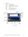
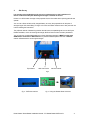
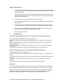
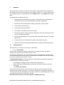
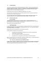
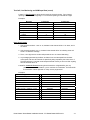
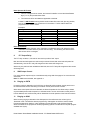
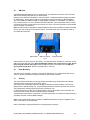
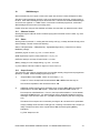
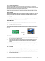
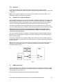
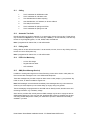
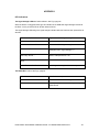
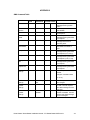
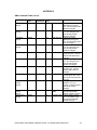
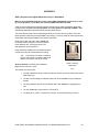
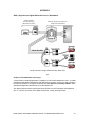
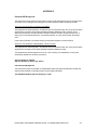
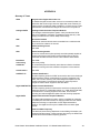
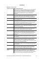
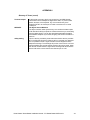
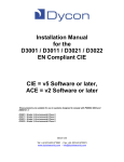
 Installation Manual
for the Duet Range:
D2600 Duet2
D2650 Duet3
Dycon Ltd
Cwm Cynon Business Park – Mountain Ash – CF45 4ER – UK
Tel: +44 (0)1443 471 060
Fax: +44 (0)1443 479 374
www.dyconsecurity.eu
[email protected]
TABLE OF CONTENTS
1.
2.
Description
Part Numbers
p.3
p.4
3.
4.
5.
6.
What to Do:
Site Survey
Installation
System Testing
Troubleshooting / Help Desk
p.5
p.6
p.6
p.7
7.
8.
9.
10.
11.
12.
13.
14.
15.
16.
17.
18.
19.
20.
21.
The Details:
Operation Description
FLT Output Relay
SMS Output Control
Ringing on PSTN
Ringing on GSM
NVM Programmable Options
Engineer Receiver Function
Aerial Siting
SIM Card
Duet Mounting
Security
SMS Messages
Using the D2355 Wired LAN Card
System Power Supply and Battery
NVM Programming
p.8
p.12
p.12
p.12
p.12
p.13
p.13
p.13
p.14
p.14
p.14
p.15
p.17
p.18
p.18
Appendix 1 ( LED Indications )
Appendix 2 (SMS Commands Table)
Appendix 3 (ADSL)
Appendix 4 (Specification & Regulations)
Appendix 5 (European PSTN Approval)
Appendix 6 (Glossary of Terms)
p.20
p.23
p.26
p.28
p.29
p.30
Duet2 D2600 / Duet3 D2650 Installation Manual – EU-D2600-D2650-INST/A10/v1
-2
Installation Manual for
D2600 Duet2 and D2650 Duet3
1.
Description
The Duet is an advanced auto-dialling digital communication device for adding GPRS, GSM, SMS and
LAN reporting to control panels that have a telephone line connection.
The Duet monitors the telephone line that is normally connected to the control panel’s digi-modem. If a
line fault is detected, the Duet sends a line fault alarm to the Alarm Receiving Centre on its radio path.
Any subsequent alarm transmission from the control panel is then sent to the ARC via the radio path.
In addition, alarms can also be sent by SMS text to mobile phones.
The Duet can be used as the primary or secondary path for alarm transmission but will be the main
path for test calls.
The Duet has 4 trigger inputs that can be activated independently.
The Duet continuously monitors the radio path. If a radio path fault is detected, the Duet allows the
control panel to dial out on the PSTN network and sends a radio fault alarm to the ARC on the LAN
path (if available).
The Duet2 D2600 can operate with control panels using DTMF Fast Format and Contact ID alarm
reporting protocols.
The Duet3 D2650 can operate with control panels using DTMF Fast Format, Contact ID and SIA
alarm reporting protocols.
The Duet will require a GSM SIM card that is enabled for ‘GPRS, GSM data and SMS’ operation.
The Duet is semi-housed in an ABS plastic case which protects the electronics and meets PSTN
safety requirements.
The Duet includes 4 outputs that can be controlled from the associated downloader or by sending
SMS messages to the unit from a PC or mobile phone.
Up/downloading telephone calls to the control panel are unaffected by the Duet.
Duet2 D2600 / Duet3 D2650 Installation Manual – EU-D2600-D2650-INST/A10/v1
-3
2.
Part Numbers
D2600-B
GPRS Duet2 (including aerial)
D2650
Duet3 (including aerial)
D1501-B
Tamper protected box with 1-amp power supply
D2454
Downloading software and NVM programmer
D2355
LAN card
D0730
Security ADSL (Broadband) filter
D0402
Products CD with manuals for all products
CS0355
NVM programming socket (USB)
A and B PSTN
connections
SIM card socket
A1 and B1
telephone
connections Aerial connector
A2 and B2
panel
connections LAN card
slot GSM and signal
strength LEDs
Communication
and path status LEDs NVM in socket
Reset and test
pins 4 inputs
Fault
relay
terminals
4 outputs
12v power
connections Fig 1 - D2600-B Duet2
Duet2 D2600 / Duet3 D2650 Installation Manual – EU-D2600-D2650-INST/A10/v1
-4
3.
Site Survey
It is strongly recommended that a site survey is conducted prior to the installation of a
Duet to confirm that adequate GPRS signal strength is available at the site.
If there is no GPRS radio coverage at the proposed site, the Duet radio alarm reporting path will not
operate.
You can use a Duet, aerial and fully charged battery to survey the proposed site for the point of
strongest signal. See Aerial Siting on Page 13 for more information. Make a note of this point and use
it when installing the Duet aerial.
The preferred method of determining whether the site has an acceptable signal is to use the Dycon
D2366 Test Meter, which will show signal strength, Bit Error Rate and other relevant parameters.
You can also use a mobile GSM telephone to show GSM signal strength. It MUST use the same
GSM network as the Duet’s SIM Card uses. A portable GPRS telephone that uses a different
network will not show the correct signal strength.
Eject Button
SIM Card Carrier
Aerial Converter
Fig 2
Fig 3 - PSTN Connections
Fig 4 - Using the D2355 Wired LAN Card
Duet2 D2600 / Duet3 D2650 Installation Manual – EU-D2600-D2650-INST/A10/v1
-5
4.
Installation
1. Site the aerial at the point of strongest signal ensuring that it is within the protected area.
This is usually the highest point in the building and well away from metal roofs and metal
walls (use Dycon D2366 Test Set). See Page 13.
2. Program the NVM for the system specific requirements using the D2454 Programmer
software. See page 18.
3. Obtain a GPRS-enabled SIM card from your GSM Service Provider.
4. Totally power down the control panel mains and battery.
5. Fit the GPRS enabled SIM Card in the socket on the Duet.
6. Where required, fit the D2355 LAN card and connect to the LAN using a CAT5 cable.
7. Fit the NVM into the 8-pin socket located at the front of the Duet. See Fig 1.
8. Connect the 4 inputs and 4 outputs as required. See Fig 1 and Page 17.
9. Connect to the FLT relay terminals as required. See Page 12.
10. Connect the aerial to the Duet aerial connector. See Fig 1.
11. Connect the control panel’s PSTN line to the A2, B2 terminals. See Fig 3.
12. Connect the user’s PSTN telephone system to screw terminals A1 and B1 provided under
the protective cover. (For security installations, only ‘serial connection’ is recommended
for other equipment that is using the same PSTN line). See Pages 17 to 23.
13. Connect the PSTN line to the A, B screw terminals. See Fig 3.
14. On the Duet, connect the ‘12v +’ & ‘12v -’ terminals to the control panel or power supply’s
12 volt output (often called ‘Aux supply’ or ‘DC power’). See Fig 1.
15. Note the SIM Card number, NVM ‘chip’ number (and any security access numbers) on the
site records that will be stored at your office.
16. Reconnect the mains supply to the control panel. The Duet is now ready for testing.
5.
System Testing
Ensure you have informed your Alarm Receiving Centre that you are ready to test your Duet.
1. Power up the Duet, the unit will initialise. This will take 40 seconds. Refer to Appendix 1
for LED indications.
2. To test all programmed reporting paths to the ARC, momentarily short the test pins
on the Duet (see Fig 1). This will cause the Duet to send a test signal to the ARC on each
path used (LAN / GPRS / GSM / SMS).
Once the test pins are shorted, communication LEDs will illuminate to indicate call
progress on each path (Green for LAN and Yellow for GPRS / GSM). During
communication the LEDs will flash to indicate the progress of the call, see Appendix 1.
The Alarm Receiving Centre should receive a test call for each path used.
Duet2 D2600 / Duet3 D2650 Installation Manual – EU-D2600-D2650-INST/A10/v1
-6
System Testing (cont’d)
3. To confirm correct operation, trigger a call to the ARC by setting the control panel so that it
sends a ‘Close’ signal. With the telephone line connected, the signal should go to the ARC
via the telephone line.
Disconnect the telephone line. The Duet should detect this and send a “PSTN Fail” signal
to the ARC via the GPRS radio path. Unset the control panel. The ‘Open’ should go to the
ARC via the GPRS radio path.
4. Contact your ARC to confirm that all signals have been received.
5. If you are using SMS signalling, check that the relevant messages have been received on
the GSM phone.
6. To cancel a call, short the reset pins, and the test pins. Remove the short from the reset
pins; wait until the Hi / Lo LEDs start to flash, then remove the short across the test pins.
7. Remember to note the SIM Card number, NVM ‘chip’ number (and any security access
numbers) on the site records that will be stored at your office.
8. Your Duet is now fully tested.
6.
Troubleshooting
Q. What if the GPRS / GSM signal has not been received by the Alarm Receiving Centre?
Check that the NVM is fitted has been correctly programmed.
Check that the SIM Card fitted has been correctly programmed i.e. it is enabled for ‘GPRS’ and for
‘Data’.
Check, using the Signal Strength LEDs (Red and Green) that the radio signal is sufficient and the
GSM path status = OK.
Check with a meter that the voltage supply to the Duet is 13.6v or more, and does not dip when the
Duet is signalling.
See Appendix 1 for GSM fault indications. These will help diagnose radio path problems.
Q. What if the LAN (IP) signal has not received by the Alarm Receiving Centre?
Check (using the LEDs) that no LAN path exists.
Check that the LAN has a route to the Internet. Ensure that firewalls, routers etc… will allow external
access.
Check that the LAN has a DHCP Server function. The LAN card requires this when first connected to
the LAN.
Check with a meter that the voltage supply to the Duet is 13.6v or more and does not dip when
signalling.
See Appendix 1 for fault indications. These will help diagnose LAN path problems.
Help Desk
If you have installed the Duet in accordance with these instructions, checked all the above points but
are still experiencing problems you can contact your Duet supplier or your Telecom Service Provider.
The Dycon web site: www.dyconsecurity.eu contains the latest copies of all manuals for all products.
Please ensure that you are working from the latest version. You can also download associated
information and software samplers. Sales, shipping and contact information is here too.
Duet2 D2600 / Duet3 D2650 Installation Manual – EU-D2600-D2650-INST/A10/v1
-7
7.
Operation
The basic operation of the Duet is to intercept communication activity from the alarm control panel or
other digital communication device (Digicom) to the PSTN and redirect it to 1 or more locations using 1
or more signalling paths. The signalling paths can be WIRED (PSTN, LAN) or RADIO (GSM, GPRS,
SMS).
The Duet performs the following functions:
7.1
1.
Intercepts alarm communication from the alarm control panel; stores the data for later or
immediate transmission and acknowledgement, according to programming;
2.
Monitors the wired and radio paths for integrity. Signals any change of status;
3.
Sends regular test transmissions;
4.
Sends regular polling transmissions;
5.
Allows SMS or downloader control of the 4 outputs;
6.
Monitors the PSTN for incoming ringing and switches the alarm control panel to the PSTN
for any downloader transmissions;
7.
Monitors the GSM network for incoming calls, either to download to the Duet, or to receive
SMS controls;
8.
Monitors the alarm control panel calls via PSTN, and intercepts if required;
9.
Operates according to NVM programmable features and options (see NVM programmer).
Call Interception
The Duet works in 1 of 2 modes: Duet Priority or PSTN Priority.
7.1.1
Duet Priority
The PSTN relay is energised, so that the control panel is connected to the Duet. All calls are
intercepted by the Duet and re-transmitted via radio or LAN.
If the radio and LAN paths fail, or if a programmable number of call attempts fails, the PSTN relay is
de-energised and the alarm control panel is connected directly to the PSTN, so that its normal calling
function may proceed as if the Duet was not there.
In DUET PRIORITY MODE, the Duet intercepts alarm communication from the alarm control panel
and, depending on programming, will either:
-
Acknowledge the message and store the data for later transmission, or
-
Store the data and immediately attempt to forward the call without sending an ACK to the
control panel.
7.1.1.1 Store and Forward
In this case, the Duet accepts the call from the alarm control panel, stores it and sends and ACK
message back to the alarm control panel. The Duet then calls the ARC and passes the message on.
The Duet works in this way automatically for 5 minutes (or whatever the “Acknowledge Timer” is set to
in programming) after every successful call to the ARC.
Note: SIA format only works in this mode regardless of NVM programming.
Duet2 D2600 / Duet3 D2650 Installation Manual – EU-D2600-D2650-INST/A10/v1
-8
Call Interception (cont’d)
7.1.1.2 Forward before Acknowledge
In this case, the Duet will attempt to forward the call before sending an “acknowledge” to the alarm
control panel. This will cause the alarm control panel to make several attempts to call the Duet.
If the alarm control panel has many Contact ID messages to send, they will be forwarded very slowly,
one call forwarded at a time, rather than using the “follow-on” call technique.
This operation may be improved by using a third technique. This will only forward the first call without
acknowledging the alarm control panel. Further calls within a short period of time will use the “store
and forward” technique. This is accomplished by programming the “Acknowledge Timer” in the
programmer to 5 minutes for example. If this timer is set to 0, then forward before acknowledge will
always operate.
7.1.2
PSTN Priority
The PSTN relay is not energised, so that the alarm control panel is connected directly to the PSTN.
This is the default state when the Duet is not powered.
The Duet monitors the PSTN line and if it fails, switches the alarm control panel to the Duet.
The Duet also monitors outgoing calls of the alarm control panel over PSTN, and if a programmable
number of call attempts fails, will switch the alarm control panel over to the Duet, for a programmable
period of time.
For example, if two call attempts fail and the third is successful, subsequent calls will be attempted
over the PSTN. However, if three call attempts in a row are unsuccessful, the Duet will switch the
alarm control panel to the Duet and intercept the fourth call, and re-transmit it over radio or LAN. In
this event, the Duet will keep hold of the alarm control panel for 10 minutes (or whatever time period is
programmed) before reverting the control panel back to the PSTN.
If the radio path fails, the alarm control panel will remain connected to the PSTN even if a PSTN fault
is detected.
Note: In this mode, if the call is made via PSTN, the SMS text function for alarm control panel calls will
not work.
7.2
Duet Line Simulator
When the Duet is connected to the alarm control panel, the operation is as follows:
1.
The Duet provides 42-45VDC to the alarm control panel simulating a telephone line
2.
When the alarm control panel goes off hook to make a call, the Duet detects the increased
current and provides dial tone to the alarm control panel (350Hz for maximum of 9 seconds)
3.
The alarm control panel dials its programmed telephone number using DTMF (if DTMF is
detected during the 9 seconds of dial tone, the dial tone is switched off). The telephone
number dialled is ignored by the Duet. The Duet will wait 3 seconds for dialling to complete,
then it will give handshake tones to the alarm control panel (the frequencies of these tones are
programmable in the NVM).
Note: if the alarm control panel dials in Loop Disconnect, as long as it takes less than 9 + 3 seconds to
complete, it will be ready to accept the HS tones from the Duet, after the 12 seconds have elapsed.
The alarm control panel will send Fast Format or Contact ID data.
4.
If the Duet receives no DTMF in response to the Fast Format handshake, it will repeat it. If it
still gets no response, it will send out a SIA handshake tone, and wait for SIA FSK data.
5.
The Duet will store the received data in its NVM and signal an “Acknowledge” tone (which is
programmable) to the alarm control panel (if the “forward immediately” option is selected, the
ACK is not sent at this time).
6.
Once a data message has been transferred to the event log NVM, the Duet will commence its
signalling function via GPRS, GSM, LAN and/or SMS, depending on programming. Once the
signalling is complete, the Duet will mark that data message as being sent.
7.
A preferred path may be selected, either wired or radio. If three calls to the preferred path fail,
the Duet may call via other paths, and rotate between them until a successful call has been
made. In the unlikely event of all calls being unsuccessful, the Duet will operate a “Fault” relay
output. This output may be connected back to the HCP or to any other equipment. This
output will remain active until a successful communication has occurred, or the Duet is reset.
Duet2 D2600 / Duet3 D2650 Installation Manual – EU-D2600-D2650-INST/A10/v1
-9
7.3
Line Monitoring
The Duet will constantly monitor the programmed paths for integrity. Should the PSTN path fail, for
example, the Duet will construct a 'PSTN Line Fail' message, using programmable details, and pass
this data message into the NVM for processing. Similarly if any other path should fail a suitable
message will be constructed and passed to the NVM.
Please refer to the Test Call and Line Monitoring NVM strings in 7.4.3 below.
Should both radio and wired paths fail, the Duet will operate the 'Fault' relay output and switch the
PSTN relay over to the alarm control panel.
If only one calling path has been programmed, and it fails, the relay output will also operate. This
output will remain active until a programmed path becomes available, or the Duet is reset.
7.4
Duet-Generated Calls
7.4.1 Test Calls
Test data messages may be set to occur at regular intervals. A single timer exists for this. If
programmed to 0, no test calls will occur. The period may be programmed from 0 to 99. The units
may be selected from Seconds, Minutes, Hours or Days.
Test calls may be programmed for any path.
7.4.2 Polling Calls
Polling calls may be set to occur at regular intervals. A single timer exists for this. If programmed to 0,
no polling calls will occur. The period may be programmed from 0 to 99. The units may be selected
from Seconds, Minutes, Hours or Days.
Polling calls may only be programmed on the GPRS and LAN paths.
Polling calls differ from alarm calls in several ways:
1.
2.
The APN (Access Point Name), IP address and port numbers are programmed
independently of the alarm details.
Only one call attempt is made upon polling timer expiry.
3.
The APN will only be changed if the previous polling call was unsuccessful.
Note: No polling calls will occur in SIA format. They will be in Fast Format 8 or 16 if the polling data is
1 or 2 characters respectively or in Contact ID format otherwise.
7.4.3 Test Call, Line Monitoring and NVM Input Data
Programming the Test Call, Line Monitoring and Input message strings in the NVM should be done as
follows (it is assumed that the reader is familiar with Fast Format, Contact ID or SIA. If not, please
refer to the appropriate alarm format specification documents).
Duet2 D2600 / Duet3 D2650 Installation Manual – EU-D2600-D2650-INST/A10/v1
- 10
Test Call, Line Monitoring and NVM Input Data (cont’d)
7.4.3.1 For Fast Format the string should contain the channel number. For 8-channel
reporting, this should be a single digit. For 16-channel reporting, this should be 2 digits.
Examples:
Message
8 Channels
16 Channels
Test Call
PSTN Line Fail
GSM Line Fail
Input 1
Input 2
9
6
7
1
2
17
16
15
01
02
Input 3
Input 4
3
4
03
04
Notes (Fast Format):
1. If the channel number is 1-8 or 01-16, the data in that channel will be '1' for alarm, and '3'
for restore.
2. If the channel number is 9 or 17, the data in that channel will be '9' indicating a test call.
There is no 'Restore' message.
3. The 4, 5 or 6 digit account number will precede the 8 or 16 channel data string.
4. Any message generated by the Duet, as distinct from one intercepted from the alarm
control panel, will have all channels not specifically being reported by the event, set to ‘5’.
The ARC personnel / computer must interpret this data correctly so as not to infer anything
from the channels set to ‘5’.
7.4.3.2 For Contact ID Format the string should contain the 3 digit identifier, plus any
partition, zone or user information, up to a maximum of 8 characters. The Duet will fill
the remainder of the 8 digits with ‘0’ if they are not programmed.
Examples:
Message
NVM data
Data transmitted
Test Call ID only
Test Call ID + Partition
602
60201
60200000
60201000
Test Call ID + Partition + Zone
PSTN Line Fail
PSTN Line Fail+ Partition + Zone
GSM Line Fail
GSM Line Fail + Partition + Zone
60201006
351
35101015
353
35302005
60201006
35100000
35101015
35300000
35302005
Input 1
Input 2
Input 3
Input 4
130
137
133
134
13000000
13700000
13300000
13400000
Duet2 D2600 / Duet3 D2650 Installation Manual – EU-D2600-D2650-INST/A10/v1
- 11
Notes (Contact ID Format):
1. The 4, 5 or 6 digit account number, the Contact ID identifier '18' and the Alarm/Restore
digit ('1' or '3') will precede these codes.
2. The checksum will be calculated and appended to the data.
7.4.3.3 For SIA Format the string should contain 2-letter SIA event code, plus any partition,
zone or user information, up to a maximum of 8 characters. The SIA restore letters are
programmed into another column.
Examples:
Message
Test Call Manual
Test Call Periodic (Auto)
PSTN Line Fail
GSM Line Fail
Input 1
Input 2
Input 3
Input 4
SIA data
RX
RP
LT1
LT2
BA01
TA01
BA03
BA04
Restore
LR
LR
BR
TR
BR
BR
Notes (SIA Format):
For the SIA restore message, the 2 characters in the Restore column will replace the first 2
characters in the data column to produce the new string. The remaining 6 characters in the
data column will be unchanged.
8.
FLT Output Relay
The FLT relay contacts, C, NO and NC are used to provide a ‘fault’ output.
Both the wired and radio paths are continuously monitored. Should both wired and radio paths fail
simultaneously, then the FLT relay will energise and the contact will change over.
Where only one path has been enabled and this fails, then the FLT relay will energise and the contact
will change-over.
9.
SMS Output Control
Four open collector outputs may be controlled remotely using SMS. See page 15 for connection and
commands.
Note: For SMS Command table, see Appendix 2.
10.
Ringing on PSTN
If incoming ringing is detected on the PSTN line, the Duet will switch the alarm control panel over to
the PSTN line and continue monitoring for the alarm control panel off-hook condition.
When alarm control panel off-hook is detected, the Duet will operate the Line Divert relay to isolate
any associated phones while the panel is in download mode. As soon as the alarm control panel onhook is detected, the Line Divert relay will be released and normal operation of the Duet will continue.
11.
Ringing on GSM
When incoming ringing is detected on the GSM path, the Duet will answer the call and go into
‘Download’ mode. This will allow remote programming / interrogation of the Duet. See the D2454
Programmer Manual for details. It is also possible to request the Duet to call the D0154 Remote
Server via GPRS for the purposes of remote programming (D0154 is a stand-alone computer program
available from Dycon).
Duet2 D2600 / Duet3 D2650 Installation Manual – EU-D2600-D2650-INST/A10/v1
- 12
12.
NVM Programmable Options
Please refer to the Duet’s NVM specifications, being the definitive reference on the NVM programming
details. The maximum call log size, using 93C86 NVM, is 63 events.
13.
Engineer Receiver Function
An engineer receiver function exists in the Duet whereby it can receive calls on the GSM network,
handle them as if they came from an alarm control panel, and put them into the NVM for further
processing. (Normally this would be to send them out on either or both of the SMS channels).
The GSM receiver function can be enabled in the NVM System information screen.
Note: If this function is selected, then the corresponding function 5.7 will be disabled.
14.
Aerial Siting
The aerial should be mounted vertically at the point of strongest signal. This is usually the highest
point in the building (often the loft area). ALWAYS do a site survey to find the area of strongest signal
before installation.
Large metal structures can affect radio signals. Avoid installing the aerial directly under metal roofs
or within metal-skinned buildings because this will reduce the signal strength and may inhibit
operation completely. If this is unavoidable, the strongest signal will be found away from the metal
roof or close to large external windows or skylights.
Avoid installing the aerial close (2 metres) to cable runs, ducting, structural metalwork, metal pipes,
water tank, electronic equipment, e.g. photocopiers, fax machines etc. These can have similar effects
as metal roofs.
The signal strength LEDs on the Duet (see Fig 1 and 2 and Appendix 1) will give an indication of
signal strength that the unit is receiving from the GSM Network.
Note: These LEDs will not work with GSM and SMS disabled in NVM.
1. Green On
2. Red and Green On
3. Red On
High signal strength
Medium signal strength
Low signal strength
Reliable operation is unlikely with low signal strength. If the LED shows that the signal strength is low,
you should improve the signal strength. This may be achieved by repositioning the aerial. The GSM
aerial lead should not be cut or extended, therefore repositioning the aerial may require that the Duet
is also repositioned.
You can use a Duet, aerial and fully charged battery to survey a proposed site for the point of
strongest signal. Ensure that the Duet is fitted with a SIM Card and NVM and that it is fully operational.
Walk around the site carrying the Duet, aerial and battery observing the signal strength LEDs. When
you have identified the point of the strongest signal, make a note of this point and use it when
installing the aerial.
To identify the best location for the aerial, use the D2366 Test Meter.
You can also use a mobile GSM telephone to show GSM signal strength. The signal strength indicator
is normally a bar or line at the side of the display on the mobile telephone.
Note: The GSM mobile telephone MUST use the same GSM network as the Duet’s SIM card uses. A
portable GSM telephone that uses a different GSM network will NOT show the correct signal strength.
There are often two or more separate GSM networks provided by different Service Providers. In the
UK, GSM networks are operated by Vodafone, O2, Orange and T-mobile.
Remember: It is always easier to find the point of strongest signal before the equipment is fitted to a
wall. Moving aerials, cables, trunking etc... after installation is wasted time and effort.
Duet2 D2600 / Duet3 D2650 Installation Manual – EU-D2600-D2650-INST/A10/v1
- 13
15.
SIM Card
A suitable GPRS/GSM SIM card may be obtained from your GSM service provider. Check if a GSM
SIM card has already been fitted by your Duet supplier.
Ensure that the SIM Card is enabled for ‘Data’ and ‘GPRS’. The Duet will not send alarms if enabled
for ‘Speech Only’. Ensure that the SIM card is enabled for incoming and outgoing SMS messages.
The Duet will not send SMS messages if ‘outgoing SMS messages’ are not enabled. The SIM card
has a number printed on it. This is the SIM card’s Serial Number. It is recommended that this number
is recorded on the site records that will be stored at your office. It will not be possible to use the GPRS
network is GPRS is not enabled.
Note: Most SIM cards are supplied for portable telephones and are only enabled for speech and SMS;
as such, they will not allow the Duet to send alarms. These SIM cards may be enabled for ‘Data’ by
your GSM service provider.
Eject Button
SIM Card Carrier
Aerial Converter
Fig 2
Using a ball-pen or pencil, push the eject button. The SIM card carrier will slide out of the Duet. Fit the
SIM card into the SIM card carrier. Wipe the SIM gold contacts with a clean tissue or cloth. Do not
touch the gold contacts with fingers. Slide the SIM card carrier into the Duet with the SIM card
gold contacts facing down. Ensure it is pushed fully in. See Fig 2.
16.
Duet Mounting
The Duet may be mounted in the alarm control panel. Alternatively, any suitable sized case may be
used. For security installations a tamper protected enclosure will be required.
17.
Security
The Duet should be protected from physical assault and tampering by being fitted inside a tamperprotected enclosure forming part of the alarm system.
The Duet has two independent methods of stopping unauthorised up/downloading. These security
features are for up/downloading only. They do not operate when the NVM is removed from the Duet
and is plugged into a NVM programming socket connected to a PC.
A ’call-back’ telephone number may be programmed so that the Duet always calls to its preset ’callback’ engineering number whenever up/downloading is requested.
A 6-digit access code must be programmed. The Duet requires this code whenever up/downloading is
requested, and when receiving SMS messages.
Note: These up/downloading security features are NOT activated when the Duet is supplied. Use of
one or more features is recommended.
Refer to the D2454 Programmer Manual for full programming information.
Duet2 D2600 / Duet3 D2650 Installation Manual – EU-D2600-D2650-INST/A10/v1
- 14
18.
SMS Messages
SMS commands may be in upper or lower case. Upper case is shown in these examples for clarity.
Should an invalid message be received, a reply to the sending phone will be sent, informing them of
the fault. Other status messages may be sent to the Duet. A full list of the available SMS messages
can be found in Appendix 2. If ‘SMS confirm’ is not ticked in the D2454 programmer, confirmation
SMS messages will not be sent to the calling phone.
Replies will be sent using the ‘Site Address’ information from the NVM. By default this text is ‘Duet:’
18.1
Software Version
Sending the keyword VER will result in the Duet replying with its software version number, e.g. 0102
Duet GPRS>
18.2
Status
Sending a blank command, i.e. nothing after the security code (e.g. 123456), the Duet will reply with a
status message. This will consist of the following:
Status : PSTN{downtime} : GSM{downtime} : Signal{GSM Signal level} : Line{PSTN Line status} :
Bat{Battery voltage}.
{downtime} is given in hours; e.g. 14.5 = 14 hours 30 mins.
{GSM signal level} is given in CSQ (value from 0 - 31); e.g. 16
{PSTN line status} is a bit map of faults, where 0 = no fault
{Battery voltage} is a true voltage reading; e.g. 12.8 = 12.8 volts.
e.g. Duet: Status: PSTN 28.2: GSM .0: Signal 16: Line 01: Bat 13.4
18.3
Output Control
The Duet has 4 open collector outputs that may be controlled remotely using the remote programmer
(D2454) or via SMS. Several message types may be sent.
1)
Output n ON or Output n OFF. Where ‘n’ is the output (1 – 4).
If output ‘0’ is sent, all outputs will be switched either ON or OFF as the case may be.
The numerical equivalent of this command is 1n1 or 1n0.
2)
Additionally several outputs may be changed at once, using the ON or OFF commands, for
example ON 13 will switch ON outputs 1, 3 whilst OFF 24 will switch OFF outputs 2, 4.
Each output has a dedicated timer. If set to 0, that output will be disabled. If set to 99m99s
that output will NOT time out. Any other time from 00:01 to 99:98 will operate the output for
that length of time and then switch off. (The OFF command effectively sets the running timer
to 0)
The status of the 4 outputs can be checked by sending the ‘O’ command with no parameters.
A Reply message will be sent to the calling phone, confirming current state of all 4 outputs. (In
reality it sends the numbers of the outputs that are ON, the remaining being OFF by
implication.)
e.g. Duet: Outputs 3,4 ON
Duet2 D2600 / Duet3 D2650 Installation Manual – EU-D2600-D2650-INST/A10/v1
- 15
18.4
Remote Reset
This is a specific command to operate Output 4. Output 4 timer should be set for 3 seconds duration.
The format of the command is ‘RR’. It operates in exactly the same way as the commands ON 4, or
141, or O 4 ON.
A reply will be sent to the calling phone: Duet: Remote Reset.
18.5
SMS number change
Sending the keywords SMS1 or SMS2 will cause the Duet to extract the calling phone’s number from
the incoming SMS message and store it in SMS number 1 or 2. (SMS0 will store it in both).
A reply will be sent to the calling phone: Duet: SMS number changed >+447890123456.
18.6
Account number
There are 4 account numbers. This command is in the format ACn aaaaaa, where n is 1 for GSM, 2
for PSTN, 3 for GPRS, 4 for LAN and 0 will change all 4. ‘a..a’.is the account number (up to 6 digits
long). If the account number is blank, it will be erased.
The numerical equivalent of this command is 20, 21, 22, 23, 24.
Note: In the Duet only the PSTN account number is used. Thus only commands AC0, AC2, 20, 22
should be used.
A reply will be sent to the calling phone. e.g. Duet: Account changed>1234
18.7
GPRS IP address and port
The 4 GPRS IP addresses and port numbers may be changed by using the commands 3n and 5n
respectively. For example 31 192.168.100.3 will change the first GPRS IP address. 53 5021 will
change the third port number (i.e. the first polling port number).
A reply will be sent to the calling phone. e.g. Duet: IP port changed>10500
18.8
LAN IP address and port
The 4 LAN IP addresses and port numbers may be changed by using the commands 4n and 6n
respectively. For example 42 192.168.100.3 will change the second LAN IP address. 60 5021 will
change all 4 port numbers.
A reply will be sent to the calling phone. e.g. Duet: IP addr changed>192.168.0.123
18.9
Telephone and Callback numbers
There are 2 telephone numbers for alarms, and one callback number. The command is 7n. For
example 71 01895474474 will change the first telephone number, and 77 192.168.100.10:45678 will
change the Callback number. Note the callback number should be an IP address for use by either
GPRS or LAN. The command 70 will change both telephone numbers.
A reply will be sent to the calling phone.
e.g. Duet: Callback number changed>81.138.0.32:1205
18.10 GSM numbers
The 2 GSM numbers may be changed by using the command 8n. For example 81 078781234567 will
change the first GSM number.
A reply will be sent to the calling phone. e.g. Duet GSM number changed>07890123456
Duet2 D2600 / Duet3 D2650 Installation Manual – EU-D2600-D2650-INST/A10/v1
- 16
18.11 Call the Download Server
Sending the keyword CALL will result in the Duet calling the Download Server. The Download
Server’s IP address and port must have been pre-programmed into the ‘Callback’ number of the Duet.
GPRS and/or wired download must have been enabled in the Duet.
If the call cannot be made by virtue of NVM parameters not being correct, the message ‘Callback
disabled’ will be sent to the calling phone, otherwise the message ‘Calling Downloader’ will be sent.
18.12 Test Calls
Sending the keyword TEST will result in the Duet triggering its normal test call sequence. A reply will
only be sent to the calling phone if the Duet is programmed to send SMS messages to that phone
normally.
18.13 RESET
Sending the keyword RESET will result in the Duet restarting, by operation of the watchdog circuit. A
reply will be sent to the calling phone before the reset takes place.
18.14 SMS Invalid
Should an invalid command be received the following reply will be sent: Duet: Invalid Command
19.
Using the D2355 Wired LAN Card
The wired LAN Card is a plug-on board that allows the Duet to be connected to a LAN. This typically
will be a LAN for office computers where cabling is Cat 5 or higher UTP cable and connectors are
RJ45 type.
Fig 4
The LAN must:
1.
2.
Have a route to the internet. This typically will be by ADSL or ISDN communications. Without
this, the wired LAN card will not operate.
Have a DHCP server function so that the wired LAN card will automatically be given an IP
address on the LAN whenever it is powered. Without this, the wired LAN card will not
operate.
Other LAN configurations are available and in most cases, the wired LAN card can be configured for
these. However, descriptions of these are beyond the scope of this manual. Please ensure that you
are fully conversant with IP, Internet and LAN conventions then contact your Duet supplier.
19.1
To install:
1.
2.
Remove power to the Duet when fitting or removing the wired LAN card.
Slide the wired LAN card into the two guides on the Duet with the metal boxed socket towards
the Duet centre. Push the wired LAN card down to ensure it connects fully to the Duet.
Using a Cat5 lead fitted with RJ45 connectors, connect the metal boxed socket on the wired
LAN card to a LAN connection point.
Re-connect the power supply.
3.
4.
Duet2 D2600 / Duet3 D2650 Installation Manual – EU-D2600-D2650-INST/A10/v1
- 17
19.2
Operation
On the metal boxed socket, where the LAN cable connects are yellow and green LEDs.
When properly connected, the yellow LED will be on solidly and the green LED will blink on once every
1-2 seconds.
Note: Any extra inputs or outputs on the LAN card are not available for use with the Duet. The 4
inputs and 4 outputs are on the Duet’s main board.
20.
System Power Supply and Battery
The Duet requires a supply of 12-13.8 volts DC at 60mA in standby and 100mA when activated, and a
battery capable of delivering bursts of up to 2A when the radio module is signalling. The installer must
ensure that the alarm system’s power supply is rated to provide adequate power for this apparatus
and for any other auxiliary apparatus drawing power from the alarm system’s power supply.
The power supply battery will be automatically tested with a short duration high current pulse every
hour. If the battery fails this test, a low battery signal will be transmitted to the Alarm Receiving Centre.
If the Duet receives its power from a power supply that is additional to the alarm system,
ensure that the 0 volt connection on the additional power supply is connected to the 0 volt
connection on the alarm system.
Only power supplies conforming to EN60950 or International Safety Standards should be used with
this apparatus. In Europe the power supply must meet the requirements of the European Directives
and carry the EC symbol.
If the supply voltage falls to the ‘low battery voltage’ limit, the Duet will send a ‘low-battery’ signal to
the ARC. When power is restored above 12.0 volts a test call (i.e. a battery voltage restore signal) will
be sent to the ARC.
Note: When the supply voltage to the Duet continues to fall below 10 volts, there will be insufficient
power for the unit to operate correctly, i.e. it will not send alarm calls to the ARC or send SMS
messages to mobile phones.
Duet2
Duet
Fig 5
21.
NVM Programming
The operating parameters for the Duet, e.g. telephone numbers, are stored in the NVM (Non Volatile
Memory). The NVM can be programmed by downloading to the Duet via GSM or by using the D2454
NVM programmer connected to a PC.
Refer to the D2454 Programmer Manual for full programming details.
Duet2 D2600 / Duet3 D2650 Installation Manual – EU-D2600-D2650-INST/A10/v1
- 18
21.1
21.2
Calling
1.
Two IP addresses for GPRS alarm calls
2.
Two IP addresses for LAN alarm calls
3.
Two GSM Numbers for alarm reporting
4.
One GSM Number, or IP address, for Secure Callback
5.
Two SMS phone numbers
6.
Two IP addresses for polling over GPRS
7.
Two IP addresses for polling over LAN
Automatic Test Calls
Periodic test calls can be sent at intervals of 1 to 99 seconds, minutes, hours or days. These timings
may be selected as Dynamic (i.e. since the last call), or Static (i.e. at fixed intervals). Test calls may
be sent on any/all signalling paths, i.e. LAN, GPRS, GSM, and SMS text.
Note: If programmed for interval of 0, no calls will be made.
21.3
Polling Calls
Polling calls can be sent at fixed intervals of 1 to 99 seconds, minutes, hours or days. Polling calls may
be sent via LAN or GPRS paths only.
Note: If programmed for interval of 0, no calls will be made.
21.4
21.5
PSTN Line Monitoring
-
24 Hour DC voltage
-
Regular dial tone detect
-
Off hook detect
SMS (Short Message Service)
In addition to sending alarm signals to an Alarm Receiving Centre via the wired or radio paths, the
Duet can send text messages to one or two GSM mobile telephones.
These text messages may be used to report an alarm event to other people, e.g. the premises’ key
holder or owner, an alarms installation engineer etc…
Note: SMS messages are not delivered immediately. Most messages take only a few seconds to
arrive but you should expect up to 20 minutes delay (or longer) during busy periods.
The text message(s) are programmed into the NVM and can identify the site, the alarm event and
monitoring information, e.g. low battery voltage.
Some service providers offer a facility where an SMS message may be sent to a pager as well as
GSM portable telephones. They may also offer ‘broadcast SMS’ where one message may be sent
onto many portable telephones. Contact your GSM service provider to determine if this facility is
available in your area.
Duet2 D2600 / Duet3 D2650 Installation Manual – EU-D2600-D2650-INST/A10/v1
- 19
APPENDIX 1
LED Indications
The Signal Strength LEDs are Red and Green. See Fig 6, page 22.
When the Duet is not triggered, these give an indication of the GSM radio signal strength received at
the Duet. A ‘once per second’ short off-blink shows all is OK.
The Signal Strength LEDs will give a signal strength indication after the Duet has been powered for 30
seconds.
LED Green On, Red Off
High received GSM signal strength
LED Red and Green On
Medium received GSM signal strength
LED Red On, Green Off
Low received GSM signal strength
LED Red Off, Green Off
GSM radio cannot hear any base stations,
GSM path fault or signal strength = 0
Either or both LED(s) On + short offblink every second
GSM radio can communicate with a local base
station, GSM path status = OK
LED Green flash once, then Red flash 3
times
Start of initialisation after a power-up or reset
Both LEDs on + Fast Flash
Initialising and waiting for SIM card ready
The GSM LED is Yellow. See Fig 6, page 22.
LED off
GSM Radio is not powered
LED on
GSM Radio module is initialising
LED slow flashes
Module powered and communicating correctly with
GSM network
Duet2 D2600 / Duet3 D2650 Installation Manual – EU-D2600-D2650-INST/A10/v1
- 20
APPENDIX 1
LED Indications (cont’d)
The Radio Communication LED is Yellow. See Fig 6, page 22.
LED off
GSM disabled in NVM programming, or Enabled but no GSM
line activity and no GSM faults detected
LED flashing on/off
NVM is blank, faulty or incorrectly programmed
LED On solid
Initialisation after a power-up or reset
LED medium flash
Dialling the receiver at the ARC
LED rapid flash (On and Off 12 times
per sec)
Handshake received from ARC, sending data to receiving
equipment
LED 6 slow flashes (On and Off 2
times per sec)
Communications successful. Data received
correctly at ARC receiving equipment
LED on for 2 sec then 3 blinks off
Up/downloading from D2454 Programmer
LED rapid flash (On and Off 12 times
per sec)
SMS Text being sent
Radio Path Failure Indications:
The yellow Radio LED will flash to indicate the type of failure. If more than one type of failure is
detected, only one will be displayed.
1 flash
No response from GSM radio network. Check aerial, signal strength, and
that the service provider is still providing a service (paid the bill?)
2 flashes
No response from GSM radio module
3 flashes
There is no SIM card fitted, or it is not fitted correctly
4 flashes
The SIM card is locked. The PUK1 code is required to unlock it
5 flashes
The SIM card PIN number is missing or wrong
6 flashes
The SIM card SMS Message Centre telephone number is invalid
7 flashes
GSM radio module fault detected by internal tests, replace unit
Duet2 D2600 / Duet3 D2650 Installation Manual – EU-D2600-D2650-INST/A10/v1
- 21
APPENDIX 1
LED Indications (cont’d)
The PSTN LED is Red. See Fig 6, page 22.
LED off
PSTN disabled in NVM programming, or enabled but no
PSTN line activity and no PSTN faults detected
LED on solid
Ringing flashes in sync with the
ringtone
1 flash
2 flashes
On line
Incoming ringing is detected and this may inhibit the Duet
from making a telephone call
PSTN telephone line DC voltage is very low or absent
Another phone (or fax, etc.) on the same PSTN line is offhook
LED on for 2 sec then 3 off blinks
Up/downloading to the alarm control panel
The LAN Communication LED is Green. See Fig 6, page 22.
LED off
LAN path not activated. Enabled but no LAN line activity
and no LAN faults detected
LED on solid
LED slow flash
On line
LAN path active. Dialling complete, waiting for connection to
ARC
LED medium flash (On & Off 5
times/sec)
LAN path active. Connected to ARC waiting for handshake
LED rapid flash (On & Off 12
times/sec)
LAN path active. Handshake received, sending data to ARC
LED 6 medium speed flashes.
Communications successful, data received correctly at ARC
LAN Failure Indications:
The green LAN LED will flash to indicate the type of line or communication failure. If more than one
type of failure is detected, the lowest number will be displayed.
1 flash
2 flashes
Unable to communicate with the plug-on LAN card
LAN path failure. 3 sequential LAN calls have failed
Green (HI)
Yellow Radio Path LED (GSM)
Red (LO)
Fig 6
Green Wired Path LED (LAN)
Yellow (SVC)
Red Wired Path LED (PSTN)
Duet2 D2600 / Duet3 D2650 Installation Manual – EU-D2600-D2650-INST/A10/v1
- 22
APPENDIX 2
SMS Command Table
Function
Security
Code
123456
Text
Command
Software
Version
Test Call
123456
VER
123456
TEST
Remote
Reset
123456
RR
Reset
123456
RESET
Call
Downloader
123456
CALL
Output n ON
123456
O n ON
Output n OFF
123456
O n OFF
All outputs
ON
123456
O 0 ON
Several
outputs ON
123456
ON 134
SMS number
change
123456
SMSn
Status
Numerical
Notes
Command Data
Unit will respond with SMS
message showing system
status.
Unit will respond with 0102
Duet GPRS>
Unit will start a manual test
call sequence.
Unit will respond with SMS
message showing the status
of all outputs.
Unit will respond with SMS
message and then do a
watchdog reset.
Unit will call the remote
downloader via GPRS or
LAN.
1n
1
Unit will respond with SMS
message showing the status
of all outputs (n=0,1,2,3,4)
1n
0
Unit will respond with SMS
message showing the status
of all outputs. (n=0,1,2,3,4)
10
1
Unit will respond with SMS
message showing the status
of all outputs
Unit will respond with SMS
message showing the status
of all outputs
Unit will respond with SMS
number
changed>+447890123456
(n= 0,1,2)
SMS text
change
Account
number
change
123456
Account
number
change
123456
123456
SMS TAny
text
AC0 1234
AC1
567890
20
21
Unit will respond with SMS
text changed
1234
Change all account numbers
to 1234. Unit will respond
with SMS message Account
Changed
567890 Change GSM account
number to 567890. Unit will
respond with SMS message
Account Changed
Duet2 D2600 / Duet3 D2650 Installation Manual – EU-D2600-D2650-INST/A10/v1
- 23
APPENDIX 2
SMS Commands Table (cont’d)
Function
IP address
change
Security
Code
123456
Text
Command
Numerical Command
Data
30
172.16.1.2
IP address
change
123456
3n
IP address
change
123456
40
IP address
change
123456
4n
IP port change
123456
50
IP port change
123456
5n
IP port change
123456
60
IP port change
123456
6n
Telephone
number
change
123456
7n
Callback
number
change
GSM number
change
123456
77
123456
8n
Notes
Change all GPRS IP
addresses to the given
one. Unit will respond with
GPRS IP changed
172.16.1.2
Change GPRS IP address
(n=1-4) to the given one.
Unit will respond with
GPRS IP changed
192.168.1.20 Change all LAN IP
addresses to the given
one. Unit will respond with
LAN IP changed
192.168.1.20 Change LAN IP address
(n=1-4) to the given one.
Unit will respond with
GPRS IP changed
8021
Change all GPRS IP ports
to the given one. Unit will
respond with GPRS Port
changed
8021
Change GPRS IP port
(n=1-4) to the given one.
Unit will respond with
GPRS Port changed
28021
Change all LAN IP ports to
the given one. Unit will
respond with LAN Port
changed
28021
Change LAN IP port (n=14) to the given one. Unit
will respond with LAN Port
changed
01443471060 Change telephone
numbers. (n=0,1,2;
0=both). Unit will respond
with PSTN number
changed
192.168.1.20: Change callback number.
8080
Unit will respond with
callback number changed
01443471060 Change GSM numbers.
(n=0,1,2; 0=both). Unit
will respond with GSM
number changed
Duet2 D2600 / Duet3 D2650 Installation Manual – EU-D2600-D2650-INST/A10/v1
- 24
APPENDIX 2
SMS Command Table (cont’d)
Function
Invalid Command
Invalid Security
Code
Security
Text
Code
Command
123456
Anything not
listed above
Numerical
Command Data
654321
Notes
Unit will respond with SMS
message showing:
INVALID COMMAND
Unit will respond with SMS
message showing:
INVALID CODE
Notes:
The security code must be 6 digits in length.
The text command OR the numeric command + data may be used.
The fields ‘security code’, ‘command’ and ‘data’ may be separated by zero or more spaces - e.g. the
following are valid commands: 123456 O 1 ON or 123456O2OFF
GPRS IP addresses 31 and 32, and ports 51 and 52 are for alarm calls only.
GPRS IP addresses 33 and 34, and ports 53 and 54 are for polling calls only.
LAN IP addresses 41 and 42, and ports 61 and 62 are for alarm calls only.
LAN IP addresses 43 and 44, and ports 63 and 64 are for polling calls only.
Duet2 D2600 / Duet3 D2650 Installation Manual – EU-D2600-D2650-INST/A10/v1
- 25
APPENDIX 3
ADSL (Asynchronous Digital Subscriber Line) or ‘Broadband’
When an analogue PSTN telephone line also carries ADSL (Broadband) signals and it is used
by a security system e.g. the Duet, then a Security ADSL filter MUST be used.
A filter is used to separate the analogue telephone signals from the ADSL (broadband) digital data
signals because the phone or security system may be disrupted or completely inhibited if ADSL
(broadband) digital data is allowed into them from the telephone line.
The D0730 Security ADSL Filter is designed specifically for use with security systems. It includes
spare terminals to aid wiring that are labelled ‘Pass Through’. This item meets all of the requirements
of the British and European telephone and security standards.
Other types of filter and plug-in filters should not
be used for series connection of a security system
to the telephone line. These types are for use
with telephones, fax machines etc…
Plug-in filters are available from the telephone service
provider and many electrical distributors including:
CPC Part Number: TE 04367 or TE04070
Farnell Part Number: 418-5328 or 506-0205
Maplin Part Number: A61AK or A72AG
Serial connection to a PSTN (and broadband)
telephone line is shown in Fig 8.
D0700 – Security
ADSL Filter
The installer must ensure that:
Fig 7
1. The user’s telephone wiring is disconnected from the NTP and reconnected to the D0730
ADSL Filter only.
2. The NTP connects only to the D0730 ADSL Filter and to no other wiring or telephone
sockets.
3. The wiring between the NTP and the D0730 ADSL Filter cannot be unplugged by the
user.
4. The user cannot plug a phone/fax etc. into the NTP.
5. The terminals 2, 3 and 5, A and B and A1 and B1 are connected exactly as shown.
Duet2 D2600 / Duet3 D2650 Installation Manual – EU-D2600-D2650-INST/A10/v1
- 26
APPENDIX 3
ADSL (Asynchronous Digital Subscriber Line) or ‘Broadband’
Analogue and ADSL
service provided by the
Network Service Provider
ADSL filter and security equipment in a
tamper protected enclosure
Duet
PSTN Connection using the D0730 Security ADSL Filter
Fig 8
Q. Why is a Broadband Filter necessary?
A. When ADSL (broadband) digital data is supplied on a normal PSTN telephone line then... an ADSL
(broadband) filter must be fitted between that telephone line and each item of ‘non digital’ equipment
because the operation of ‘non digital’ equipment may be disrupted or completely inhibited if ADSL
(broadband) digital data is allowed into it from the telephone line.
‘Non digital’ equipment means anything that would be used on a normal analogue PSTN telephone
line, i.e. a phone, fax machine, Duet, digital communicator, control panel digi-modem.
Duet2 D2600 / Duet3 D2650 Installation Manual – EU-D2600-D2650-INST/A10/v1
- 27
APPENDIX 4
Specification
Models
D2600-B Duet2
D2650 Duet3
Dimensions (h x w x d)
25 x 175x 120 mm
Weight
200 grams
Telephone Path
PSTN technology, CTR21 approved
Radio Path
GSM
Power Requirement
12.0 - 13.8volts DC, 0.1volt max ripple
Current Consumption
60mA quiescent, 100mA operating
Low Battery
10.8-11.0 volts falling, 11.8-12.0v recovery
Outputs
Aux = 1 changeover relay (24v 1A contacts)
Prog = o/c 100mA to 0v
Temperature
-20C to +60C transit, -4C to +50C operating
Humidity
0 - 80% non-condensing
Mounting
Any orientation
Warranty
2 years
Regulatory Constraints
Before attempting to install the Duet, the installer must be aware that the Duet may only be installed by
a professional installer.
The Ringer Equivalence Number (REN) of the apparatus is 1.0. The sum of RENs of the individual
items connected to any one analogue PSTN line should not exceed 4.
Duet2 D2600 / Duet3 D2650 Installation Manual – EU-D2600-D2650-INST/A10/v1
- 28
APPENDIX 5
European PSTN Approval
The Duet product range meets the requirements of the EU PSTN standard CTR21 and is approved for
connection to any exchange line forming part of a Public Switched Telephone Network (PSTN).
AHCTR210 001 Declaration of Network Compatibility
The equipment has been approved in accordance with Council Decision 98/ / EC (5) for pan-European
single terminal connection to the Public Switched Telephone Network (PSTN). However, due to
differences between the individual PSTNs provided in different countries, the approval does not, of
itself, give an unconditional assurance of successful operation on every PSTN network termination
point.
In the event of problems, you should contact your equipment supplier in the first instance.
AHCTR211 001 Statement to Notified Body, Vendor and User
The equipment has been approved in accordance with Council Decision 98/ / EC (5) for pan-European
single terminal connection to the Public Switched Telephone Network (PSTN).
The equipment has been designed for use in all 17 EU countries, plus Switzerland, but may have
interworking difficulties in Germany and Greece.
Approval Authority: CE0168
Approval Number for Duet range: 608777
International GSM Approval
The Duet product range incorporates an independently tested and approved GSM radio module that
meets the requirements of International radio communication standards.
The GSM Radio Module Approval Authority is: 0681
Duet2 D2600 / Duet3 D2650 Installation Manual – EU-D2600-D2650-INST/A10/v1
- 29
APPENDIX 6
Glossary of Terms
ADSL
Asynchronous Digital Subscriber Line
A ‘wideband’ digital communication service from a network provider to a
subscriber that carries a high volume of digital data, most commonly for
internet access. Sometimes called ‘broadband’. An ADSL service is often
provided with a simultaneous analogue PSTN service on a hybrid line.
Analogue PSTN
Analogue Public Switched Telephone Network
The analogue national telephone system. Often just called the PSTN.
Service is available to customers on twisted-pair wires that carry a DC
supply provided from the network telephone exchange.
APN
Access Point Name
Identifies an external network that is accessible from a mobile terminal.
E.g.The APN for Vodafone is “internet”.
ARC
Alarm Receiving Centre
See ARS.
ARS
Alarm Receiving Station
A 24 hour manned centre (often privately owned & operated) capable of
receiving and logging calls of alarm and forwarding them to security
authorities and other relevant services. Often called a central station.
Broadband
See ADSL.
Call Clearing
See 3-way-calling.
Call Minder
A call answering service offered by some telecomm Service Providers
where an incoming call to the subscriber’s telephone is not answered.
Central Station
See ARS.
CONTACT I D
Contact Identification
An alarm reporting protocol of DTMF tones used to send via an Analogue
PSTN telephone network a transmission to receiving equipment at an
ARC, and to receive checking and acknowledgement replies from that
receiving equipment. The Contact ID protocol is commonly used in
burglar or intrusion alarm equipment. See also DCID.
Digital CONTACT ID
Digital Contact Identification
An alarm reporting protocol of data used to send via an Analogue PSTN
telephone network or a digital data network, e.g. VDN, GPRS, GSM data,
a transmission to receiving equipment at an ARC, and to receive
checking and acknowledgement replies from that receiving equipment.
Digital PSTN
Digital Public Switched Telephone Network
The digital national telephone system. Service is available to customers
on twisted-pair wires that carries a DC supply provided from the network
telephone exchange, on optical fibre or other digital transmission
medium. The digital service may be in ISDN format or another digital
format.
DTMF
Dual Tone Multi Frequency
The series of tones used by telephones to send dialling information to an
analogue PSTN exchange. These tones are also used by the DTMF Fast
Format and Contact ID alarms reporting protocols.
Duet2 D2600 / Duet3 D2650 Installation Manual – EU-D2600-D2650-INST/A10/v1
- 30
APPENDIX 6
Glossary of Terms (cont’d)
DTMF Fast Format
Dualcom96
EEPROM
GSM
GPRS
Hybrid Line
NTP
NVM
PABX
PSTN
SMS
SMS Message
Centre
Alarms Reporting Protocol
A protocol that is a sequence of analogue tones (push-button telephone
tones) used to send via telephone lines a transmission to receiving
equipment at an ARC, and to receive checking and acknowledgement
replies from that receiving equipment. 8 or 16 channel DTMF Fast
Format protocol is commonly used in burglar or intruder alarm
equipment.
Alarms Reporting Protocol
This protocol is used by Duet to send transmissions to receiving
equipment at an ARC, and to receive checking and acknowledgement
replies from that receiving equipment. This is a modem type protocol.
Electrically Erasable Programmable Read Only Memory
A type of NVM. See NVM.
Global System for Mobile Communications
Digital telephone service particularly (but not exclusively) for users that
may be mobile for carrying digital data, speech or fax, where the path
from the user is by a radio link to one (or more) fixed sites.
General Packet Radio System
A digital telephone service for users that may be mobile for carrying
digital data (typically internet) where the path from the user is by a radio
link to one or more fixed sites.
A line that carries digital data and analogue signals simultaneously. Most
commonly this is an ADSL digital service and an analogue telephone
service on one line from a Service Provider to a subscriber.
Network Termination Point
A telephone line is terminated at the users premises by a Network
Termination Point which is provided by the Telecoms Service Provider.
This is a socket or connection where the user’s equipment can be
connected.
Non Volatile Memory
An integrated circuit memory device that does not need any power to
remember data.
Private Automatic Branch Exchange
A small telephone exchange for use within one building or group of
buildings. Commonly used in businesses where each phone in that
business is an extension on that PABX. Usually connects to one or more
analogue PSTN or ISDN telephone lines.
Public Switched Telephone Network
A national telephone system. This may be analogue and/or digital. See
Analogue PSTN.
The GSM Short Message Service
Service provided by companies supplying a GSM communications
system where a short text message may be sent to (and from) GSM
mobile phones and read on the GSM mobile phone display.
SMS messages are not sent ‘directly’ from one GSM phone (or Duet ) to
another GSM phone. All messages are first sent to a Message Centre
operated by the GSM Network Provider and then forwarded to the
selected mobile phone(s). This normally takes a few seconds but delays
of 30 minutes or more may be experienced during busy periods.
Duet2 D2600 / Duet3 D2650 Installation Manual – EU-D2600-D2650-INST/A10/v1
- 31
APPENDIX 6
Glossary of Terms (cont’d)
Terminal Adapter
WEB SITE
3-Way-Calling
A device that connects to the S-bus connection of an ISDN Network
Termination Point and adapts the digital S-bus data, i.e. protocol, data
speed, structure, to that required. E.g. the conversion may be to
analogue PSTN or to a serial port for cable connection to a PC serial
‘COM’ port.
The Dycon Internet Web Site
The Dycon web site: www.dyconsecurity.com contains the latest copies
of all manuals for all Dycon products. Please ensure that you are working
from the latest version. You can also download associated information
and software samplers. Dycon sales, shipping and contact information is
here too.
This is a service provided by some telecommunication service providers.
BT in the UK offer this service. When a call is in progress on a telephone
line it is possible to send a signal via that line to the equipment at the
telephone exchange. The exchange will put the current call on ‘hold’ and
provide a dialling tone so that another outgoing call may be made. When
this second call has finished a signal to the exchange will disconnect the
second call and re-connect the first one that was put on ‘hold’.
Duet2 D2600 / Duet3 D2650 Installation Manual – EU-D2600-D2650-INST/A10/v1
- 32