1
MODEL HF-81
DUAL 14 WATT HI-FI
STEREO AMp·PREAMP
general description
GENERAL
channel) and two auxiliary Binputs (one in each channel).
nout Selector switch on front panel has positions for feednpur serecror swiren on rronr panel nas polil I lun::o lUI ."''''... ing FM tuner output to one channel and AM tuner to
other, or FM tuner to one channel and FM Multiplex
adapter output to other.
I
The EICO Model HF-81 is a complete high fidelity stereophonic control center and a pair of 14watt amplifiers, all
on one chassis. With it you can select preamplify, and
control accurately any stereophonic source (tape, discs, or
broadcasts) and feed it through the self-contained dual 14
watt amplifiers to a stereo pair of speaker systems. When
you playa monophonic source, the 14 watts available per
channeI adds up to a total of 28 watts for your two speaker
systems. If you desire, both amplifiers can be connected
in parallel and driven byone preampIifier-control section
while the other preampl ifier-control section is free to drive
an external power amplifier. In this way your old amplifier can be put to use in a stereophonic system. Construction is of the "low silhouette" type that permits you to
dispense with cabinetry if desired.
3. May be used as either two independent amplifierpreamplifiers,or one preamplifier-control section may be
set free to operate an external power amplifier and the
other preampl iFier-control section used to drive both internal power amplifiers connected in parallel at the
speaker connection terminals. A top - of-chassis slide
switch permits choice of operation .
4. Ganged level controls and a separate focus (balance)
control.
5. Independent full-range bass and treble tone controls
in each channel. Tone controls of the low distortion
variable cross-over feedback type.
FEATURES
6. Identical Williamson type, push-pull EL84power amplifiers with high quality output transformers.
1. Separate low level input in each channel for mag.
phono, tape head, and microphone. Circuitry carefully
designed to provide the high gain required by tape heads
and high quality, lowoutput mag. cartridges without hum
and noise problems. A front panel switch permits choice
of the proper NARTB tape head equalization for either
7 1/2 & 15 or 3 3/4ips tape speeds.
7. Hum balance control, panel-mounted fuse, pi lot lamp,
convenience outlets.
8. EICO "low silhouette" construction employing horizontal chassis for proper layout and component separation.
Easyconsole installation, if desired, with complete shielding and adapatability to any panel thickness.
2. Separate high level inputs for AM, FM, and FM
Multiplex. Also two auxiliary A inputs (one in each
Copyr ight
1
©
1958 Electronic Instrument Compan y, Inc .
SPECIFICATIONS
*
** Hum & Noise Level (below rated output): mag. phono -
Output Power: 28 watts continuous; 56 watts peak.
60db; tape head - 51 db; mic - 57 db; tuners, auxll iaries - 75 db.
1M Distortion (60c &7kc at 4: 1): 2% at 28 watts; 0.5%
at 10 watts.
Tone Control Range: ±15db at 50c and 10kc.
Frequency Response: (2w):I:O. 5db 10c to lOOkc.
Speaker Connections: 4,8, and 16 ohms.
HarmonicDistortion: 16 watts at less than 1% 30c to lOkc;
20 watts at Iess than 1% 40 c to 10 kc; 28 watts at
less than 1% 50c to 5kc; 8.4 watts at less than
2% at 20c.
Tubes: 4 - ECC83/12AX7, 2 - ECC82/12AU7, 4- EL84,
2 - EZ81.
Size: 15" wide, 4 3/4" high, 10 1/2" deep.
Transient Response: excellent square wave reproduction
(4usec rise time) negligible ringing, rapid settl ing
on 10kc square wave.
Transient Distortion (60 cps tone burst):
full power.
Weight: 241bs.
* Where
power output is involved, figures are given for
two channels combined; divide power output figures by
two for specifications of each channel alone. Design
property specifications refer, of course, to either or both
channels.
less than 1% at
Inverse Feedback: 20db
** Measured with tone controls set "flat", LEVEL control
maximum, and FOCUS control set for maximum gain in
channe I checked.
Stability Margin: 12db
Damping Factor: above 8,20 cps - 15 kc,
Sensitivity (input for rated output): mag. phono 4mv;
tape head 7.5 ips - 2 mv; tape head 3.75 ips 3.5mv; mic - 6mv; tuners, auxiliaries - 0.5V.
2
mechanical installation
GENERAL
CONSOLE MOUNTING
a) HEAT DISSIPATION (VENTILATION): In common with
other electronic equipment, the HF-81 produces considerable heat in normal operation. Unless continuous and adequate air flow isobtained around the heat producing elements, these elements will over-heat and their useful life
will be greatly curtailed.
a) 0 erations on console front anel reI iminar to am Iifier mounting: 1 Tape the panel template provided to
the face of the console so that the top of the mounting surface line on the template is level with the top of the
amplifier mounting shelf. Note: When shelf is not available, tape the template at any convenient spot on the face
of the console. (2) Use an awl or a nai I to pierce the
centers of the four extreme outer holes for mounting the
control plate)' to transfer their locations to the console
panel beneath. (3) Trace out the rectangular cutout with
an awl or nail and then pierce the centers of the four 1/2"
holes)' one in each corner of the cutout. (4) Remove the
panel template. (5) Drill the four 1/2" holes in the console panel, one in each corner of the rectangular cutout
area. Cut out the rectangular piece with a keyhole saw)'
using the four 1/2" holes as starting holes.
It is useful to understand the process of convection whereby heat is removed in judging the suitability of a location.
Air heated by the heat-producing elements expands and
rises; cool air is drawn from beneath to take the place of
the heated air. In this manner, a stream of air is set in
motion which continually removes heat from the amplifier. (In particular, we are mainly concerned with the
major heat-producing elements; the four EL84 output tubes
and the two EZ81 rectifier tubes.) If there is any impediment to or constriction of the airflow, the essential process
of heat removal will be adversely affected.
b) Am Iifier mounting in console: (1) Pull off the control
knobs. 2 Remove the four screws that fasten the bezel
to the side pieces and remove the bezel. {3} Remove the
two screws and nuts that fasten the control plate to the
bezel. The bezel is not used in console mounting. ~)
Fasten the control plate to the console panel with the two
#4x3/8 wood screws supplied. (5) If the rubber feet have
been inserted irwhe bottom plate)' remove them. (They may
be pried out with a thin screwdriver.) (6) Place the unit _
on the mounting shelf and slide it forward until the slide
Adequate ventilation will be provided if the amplifier is
installed in an open-back console provided that the top
of the amplifier is spaced at least two inches below any
shelf mounted above it. If the cabinet is enclosed at the
rear, provide several large holes or slots as low down and
as high up in the cabinet back as possible. As an alternate, holes may be provided in the sides, bottom, or top
of the cabinet. The important thing to remember is that
_
~ff~~ti~e ve~tiiation requires provis~n for
cooi air to enter at the bottom and hot air to leave at the top.
•
__.
~
_1
t
I
I
switch support bracket is up against the panel and the
slide switch accessible from the front; the control shafts
should be approximately centered in the corresponding
holes in the control plate. (7) With a sharp pencil, draw
the outl ine of the side and rear bottom edges on the chassis
shelf. As the bottom plate falls short of the full width by
3/16" on each side)' draw new side edge lines 3/16" inside the original side edge lines. (8) Now remove the
knobs and take the chassis off the shelf. (9) Remove the
6screws which fasten the bottom plate to the chassis. (10)
Place the bottom plate exactly in the outl ine drawn on the
shelf and mark the position of the center hole on the left
side and the center hole on the right side. (11) Remove
the bottom plate and drill each of the marked holes on the
shelf to a diameter of 1/4". (12) Refasten the bottom
plate to the chassis, with the four of the six#8x3/8screws
previously removed, using the two holes at the rear and the
two holes at the front of the chassis. (13) Replace the
chassis on the she lf, positioning it exactly in the outline
previously drawn, and restore the knobs. This time make
sure that the indicator dot on each knob agrees with the
control position. (14) From the bottom side of the shelf,
insert a #8 x I" screw, with a 1/2" flat washer against
the head, through both the left and right side center holes.
These screws engage the stamped nut over each hole on
the chassis flange and when tightened secure the chassis
to the shelf.
]f the amplifier is not installed in a console, it may be
situated on an open surface or on a shelf of a bookccse,
Four rubber feet are also provided so that the amplifier will
not mar the surface of furniture on which it is placed.
b) EASY ACCESS TO CONTROLS: Mount the amplifier
at a height which will permit easy manipulation of the controls. Tuner controls should be located nearby.
c) ACCESSIBILITY TO PARTS:. Tubes are the most frequently replaced items in electronic equipment. If the
amplifier is installed in a console, sufficient space should
be alloted to reach and remove any tube in the amplifier.
Furthermore, input and output terminals of the amplifier
should be accessible to permit easy interchanging of system components for comparison, and connection or disconnection of a portable tape recorder which is stored away when not in use. If antennas are strung around the
back of the console in which the amplifier is installed,
arrange them so they will not interfere with access to the
amplifier.
d) ACOUSTICAL ISOLATION: If amplifier and speaker
are installed in the same cabinet (not recommended), provide sufficient separation to minimize mechanical speaker
vibration reaching the amplifier. The minimum separation
is about one foot.
3
electrical installation
CH.2
The HF-81 can be used in two ways for a stereophonic
system. In all cases, plug monophonic sources and one
track of monophonic/stereophonic sources in the channel
1 inputs; plug the other track of stereo sources in the channel 2 inputs. It is assumed in what follows that a stereophonic phono cartridge is being used . Monophonic phono
refers to playback of a monophonic recording with a stereophonic cartridge.
32
16
G
32
TO MATCHING
TAP
4
G
SPKR.I
FIG. 10. SPEAKER CONNECTIONS
CH.l
TAPE OUT
--I
I
t
r
.
CH.2
TAPE OUT
CH.l HIGH
LEVEL INPUTS
CH.l
TAPE OUT
L-- SPEAKER
~
CH.I
--II PO~~.~AMP ~ SP~~;R
Ip~:,~p~!
CH.2 HIGH
LEVEL INPUTS
POWER AMP
CH.l
1--_ _ SPEAKER
CH.I
CH.l LOW
LEVEL INPUTS
FIG.ld
STEREO NORMAL
CH.2 LOW
LEVEL INPUTS
S
TO MATCHING
TAP
r:r<5NEl
CH.I LOW _--_IPREAMPt
LEVEL INPUTS
. CH.I ~
CH. 2 LOW
LEVEL INPUTS
16
SPKR.2
CH.I HIGH
LEVEL INPUTS
FIG.lc
CHECK AMPL. 2
.4
8
(J) (]) (J) (J) ()
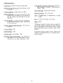
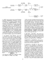
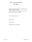
a) INTERNAL POWER AMPLIFIERS OPERATED SEPARATELY, EACH DRIVING ONE SPEAKER OF A STEREO PAIR.
This arrangement is used when there is no other amplifier
the user desires to include in the system. The SERVICE
SEL.sl ide switch on top of the chassis must be set to SEParate. Signal connections are all internal, so only the
speaker connection need to shown (Fig. la, rear chassis
view). The internal arrangemention in the HF-81 at each
of the positions of the FUNCTION selector are shown in
Figs. lb, lc, ld, le, H, and Ig, as an aid to understanding the operation with this arrangement.
FIG.lb
CHECK AMPL. 1
CH.I
I
SERVICE SEL.
:" W""'ER
:":"""AM
-:-:-:"P
::-1L - - SPEAKER
P""'O. CH.2
~ CH.2
PREAMP~ SEP • • •
1
CH.2 I
19!:2J
~
CH.2 HIGH
LEVEL INPUTS
CH.2
TAPE OUT
CH.l HIGH
LEVEL INPUTS
CH.I
TAPE OUT
jr-
CH.I LOW
LEVEL INPUTS
1-_'- SPEAKER
CH.2 LOW
LEVEL INPUTS
1--_ _
CH.l
FIG.le
STEREO REVERSE
CH.2HIGH
LEVEL INPUTS
4
CH.2
TAPE OUT
SPEAKER
CH.2
CH.I HIGH
LEVEL INPUTS
CH.I
TAPE OUT
1-_ _ SPEAKER
CH.I LOW
LEVEL INPUTS
CH I
FIG.1f
MONOPHONIC TUNER,
TAPE, TV
SEP
1---_ SPEAKER
CH.2
CH.2
TAPE OUT
CH. I
TAPE OUT
CH. I HIGH
LEVEL INPUTS
I--_ _ SPEAKER
CH. I LOW
LEVEL INPUTS
CH. I
FIG. 19
MONOPHONIC PHONO
CH.2 HIGH
LEVEL INPUTS
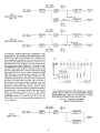
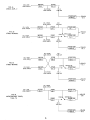
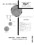
b) INTERNAL POWER AMPLIFIERS COMBINED (TIED
TOGETHER AT THE INPUTS AND PARALLELED AT THE
OUTPUTS) TO DRIVE ONE SPEAKER OF A STEREO PAIR.
This arrangement is employedwhen the useralready has a
high quality amplifier (usually 20watts or more if it is to
be worthwhile) which he desire to include in the system.
The oreamo-tone control combination including the regltie preamp-Tone conrroi COmOlnUJlUlI 11I"'IU\,llll~ " " " '''''l:fular CHI·tone control feeds the combined internal power
amplifiers; the preamp-tone control combination including
. the regular CH2 tone control feeds out through the CH2
TAPE OUT jack to an external power amplifier. The SERVICE SELECTOR switch on the chassis must be set at the
COMbined position for this service in order to disconnect
the input of the CH2 power amplifier from the output of
the CH2 tone control and connects it instead to the input
of the CH1 power amplifier. The CHI and CH2 power
amplifiers are paralleled at the outputs, as shown, by an
external jumper connected between corresponding speaker
connection taps . The external signal connection and the
speaker connections are shown in Fig. Zc, The internal
arrangements in the HF-81 at each of the positions of the
FUNCTION selector are shown in Figs. 2b, 2c, 2d, 2e,
2f, and 2g, as an aid to understanding the operation with
this' arrangement.
2
If-__ SPEAKER
I
• CH.2
CH.2
TAPE OUT
TAP!:
OUT
o
CH.2
32
4
16
CH.I
__
G
32
~_~ ~
.-
-
-
- - -
- -
EXTERNAL BASIC
POWERAMPLIFI ER
-
8
-
p
- - -
~I
~I
4
G
(J)
I
,
I
I
I
. I
'
~,
"INPUT
16
~
-
-''- -- -- --- '1
::11
:Q
itl
'"
~
"'I
0,
o
""I
I
co
1
I
I
1
-
* On
integrated amplifiers HF20, HF32 feed into TAPt
OUTPUT [eekj en HF52r feed into ELECTRONIC CROSSOVER INPUT jack, after severing connection between
ELECTRONIC CROSSOVER IN and OUT jacks.
FIG. 20. SPEAKER & EXTERNAL
SIGNAL CONNECTIONS.
CH.I HIGH
LEVEL INPUTS
FIG.2b
CHECK AMPL. 1
SERVICE SEL
POWER AMP
•
CH.2.
~SEP.,
CH.2
CH.2 LOW
LEVEL INPUTS
CH.I
TAPE OUT
CH.I LOW
LEVEL INPUTS
SPEAKER
CH.I
5
FIG.2c
CHECK AMPL. 2
CH.2 LOW
LEVEL INPUTS
CH.2 HIGH
LEVEL INPUTS
CH.2
TAPE OUT
_ SPEAKER
CH.2
CH. I HIGH
LEVEL INPUTS
CH.I
TAPE OUT
CH.I LOW
LEVEL INPUTS
FIG.2d
STEREO NORMAL
SPEAKER
CH.I
CH.2 LOW
LEVEL INPUTS
CH.2 HIGH
LEVEL INPUTS
CH.2
TAPE OUT
_ SPEAKER
CH.2
CH.l LOW ...
LEVEL INPUTS
_
FIG.2e
STEREO REVERSE
SPEAKER
CH.I
CH.2 LOW
LEVEL INPUTS
CH.2 HIGH
LEVEL INPUTS
CH.2
TAPE OUT
I--_--.:SPEAKER
CH.2
CH.l HIGH
LEVEL INPUTS
CH.l LOW
LEVEL INPUTS
SPEAKER
CH.l
FIG.2f
MONOPHONIC TUNER,
TAPE, TV
CH.2
TAPE OUT
I
!
POWERAMP I, _ _--=SPEAKER
• CH.2
~----. EXTERNAL"'"'
6
CH.l HIGH
LEVEL INPUTS
CH.l
TAPE OUT
CH.l LOW
LEVEL INPUTS
FIG.2g
MONOPHONIC PHONO
SPEAKER
CH.l
CH.2 LOW
LEVEL INPUTS
CH.2 HIGH
LEVEL INPUTS
CH.2
TAPE OUT
f - - - SPEAKER
CH.2
* NOTE: All ceramic cartridge manufacturers have developed simple networks which when connected the outputs
of their cartridges result in a characteristic identical to
that of magnetic cartridges. By interposing the recommended adaptor for the particular ceramic cartridge between the cartridge outputs and the MAG. PHONO inputs of the amplifier, it is possible to use the MAG. PHONO
inputs for the ceramic cartridge with excellent results.
Adaptor networks are given in the literature for the particular ceramic cartridge and can be built on a terminal
strip mounted on the underside of the phonograph base, or
may be available in convenient component form from the
cartridge manufacturer. Stereol;lhonic crystal cartridges
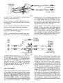
c) INPUTS: There are identical pairs of MAG. PHONO,
TAPE HEAD, MICROPHONE, AUXILIARY A, and AUXILIARY Binputs -one of each pair in channell and channel 2 - and each is identified accordingly by the suffix
1 or 2. The MAG. PHONO, TAPE HEAD, and MICROPHONE pairs of inputs are all "low level" inputs, meaning that they all feed through a preamplifier/equalizer
stage in either channel 1 or 2. The AUXILIARY A and
AUXILIARY Bpairsofinputs are "high level" inputs, meaning that they enter either channel 1 or 2 at a point after
the preampl ifier/equalizer stages. The AM, FM and FMFM Multiplex inputs are also "high level inputs", which
nr", intArnnllv ~"'IA...,t",rl in nnir~ - nn", fnr ",n...,h ...,hnnn"'l
ccrrrrcge mcnurccrurer,
are Interne y se ectea In pal rs - one for each channe
- by the INPUT SEL. switch. At the MONAURAL position of the FUNCTION SEL., AM only is selected at the
AM-FMposition of the INPUT SEL., and FMonlyis selected at the FM- FM MULTI. position of the INPUT SEL.
orereopnoruc crysTal carrnages
(Ronette "Binofluid" OV and BF40) can be connected directly to auxiliary high level inputs.
2} TAPE HEAD 1, TAPE HEAD 2: These inputs are intended for direct connection to the two outputs of a stereo
tape playback head. A front panel slide switch permits
choice of NARTB tape head equalization either for71/2
(& 15) ips or3 3/4 ips tape speeds. The loading resistance
presented by each tape head input is 100,000 ohms.
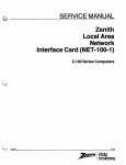
l) MAG. PHONO 1, MAG. PHONO 2: These inputs
are intended for the two outputs ofa stereo magnetic cartridge, or for a stereo ceramic cartridge with adaptors.
The correct method for wiring a three terminal cartridge
is shown in Fig. 3. If the cartridge is a four terminal
type, short the two inside terminals of the cartridge together and treat it exactly as if it were the single center
terminal shown in Fig. 3. The loading presented to each
output of the cartridge by each MAG. PHONO input is
100,000 ohms. If a lower loading resistance is required
by the particular cartridge used, connect a shunt resistor
of appropriate value from each outside terminal of the cartridge to the center (common) terminal. This can be done
actually by mounting a 3-post terminal strip on the underside of the phonograph mounting board at a point near the
lead break-out from the pickup arm. These shunt resistors
are then wired to this terminal strip as shown in Fig. 3.
The value of each of the two shunt resistors (Rs) can be
determined fromthe desired loading resistance (RI) by this
formula
Rs = 100,000 x RI ohms
100,000 - RI
or th is tabl e; for RI = 50KQ, use Rs = 1OOKQ; for RI :: 33KQ,
use Rs = 50KQ; for RI = 25KQ, use Rs = 33KQ.
3} MICROPHONE 1, MICROPHONE 2: These inputs are
intended for rec~~:ving the output signals directly from
two separate microphones. It is preferable that the microphones used be of the high impedance type.
4) AUXILIARY A1, AUXILIARY A2: These inputs are
intended for either a stereophonic or monophonic high
level source. A stereophonic high level source might be
a stereo tape deck with built-in playback equal ization
for both tracks. A monophonic high level source might
be a monophonic crystal cartridge or tv sound. Plug a
monophonic source intoAUXJLlARY A 1, leaving theAUXILIARY A2 input unused. Note that the input impedance
at all these high level inputs is 0.5 megohm, which is too
low for ceramic cartridges requiring 2 to 3 megohms input impedance. For ceramic cartridges, use the MAG.
PHONO inputs with the simple adaptor networks recommended by the manufacturers. For stereophonic crystal
cartridges (Ronette "Binofluid" OVturnover and BF40 single needle), the 0.5 megohm load provided at the high
level inputs is exactly the loading impedance required.
7
STEREO MAG.
CARTRIDGE
~ ~ ~~ -~,
-
(8-
I
TO MAG. INPUT 1
B-1
TO MAG. INPUT 2
FIG. 3
5) AUXILIARY B'l, AUXILIARY B2: Same as for AUXILIARY AI, AUXILIARY A2 above.
mentioned sources to the correspondmg amplifier input
jack. Unless the source has a low-impedance output such
as a cathode follower (with which up to 50ft. of cable
can be used), use the shortest possible connection and
low - capacity shielded cable (cable having os low as
25mmfd capacitance per foot is available).
6) AM: This input is intended for AM tuner or the AM
output of an FM-AM tuner where the FMand AM sections
are independent.
7) FM: This input is intended for an FMor FM-AM tuner
where the FM and AM sections are ~ independent.
d) TAPE OUTPUT I, TAPE OUTPUT 2: When no external
amplifier is used in the system, both these outputs are
available for feeding out to a stereo recorder. When an
external power ampl ifier is used in the system, TAPE OUTPUT 2 is used to feed out to the external power amplifier.
If it is desired to do stereo recording under the latter
conditions, construct a device such as shown in Fig. 4.
Use low capacity shielded cable for connections.
8) FM MULTIPLEX: This input is intended to receive the
output from an FM Multiplex adaptor.
NOTE: A shielded cable with a shielded "phono-type"
plug should be used to connect from each of the above-
HF81
TAPE
,",liT
OUT
~-----~
TO INPUT 1
~OFSTEREO
U~
RECORDER
IV
...
'.
lI"1ru I
,L
OF STEREO
RECORDER
-dJ
"'-----~
._-
TO INPUT 2
2 - PHONO RECEPTACLE
STRIP
1'"'--_----:....8
I!l
(8
I!l
6,
TO EXTERNAL
POWER AMPLIFIER
FIG. 4
e) POWER CONNECTIONS: The line cord of the HF-81
must be plugged into a house outlet providing normally
117 volts , 60 cycles AC power. A convenience receptacle on the rear chassis can be used, if desired, with a
cube tape to provide 117VAC power to the associated
equipment. This convenience receptacle is not switched
or fused and provides 117VAC at all timeS;-regardless
of whether the HF-81 is turned on or off.
follows: With your ear held close to the speakers, insert
the amplifier power plug into the wall outlet and listen
to the hum level. Now pull out the plug and re-insert it
with the prongs reversed. Choose the prong position with
the least hum. Now connect the tuner input connector to
the amplifier input jack, and with the tuner set between
stations and the tuner volume control set at a minimum, do
the same with the power plug of the tuner; use either the
117VAC receptacle on the HF-81 or one receptacle of a
cube tap inserted in the 117VAC receptacle on the HF-81.
Next, connect the phono cartridge leads to the MAG.
PHONO 1 and 2 Inputs, and, with turntable off and pickup arm at the rest position, find the insertion position of
the turntable line cord plug that yields lowest hum. Finally, connect the tape head leads to the TAPE HEAD 1
and 2 inputs, and, with the tape deck turned off, find the
insertion position of the tape deck line cord plug that results in lowest hum. When all of this is completed, adjust the humbalance control on top of the amplifier chassis
for least hum.
HUM ADJUSTMENT
After checking the ampl ifier for proper operation, remove
all input cables to the amplifier and make the following
control settings which hold throughout the process of hum
adJustment: INPUT SELECTOR at PHONO, FUNCTION
SELECTOR at STEREO, FOCUS control at 0, LEVEL control at 10r both TREBLE controls at -5, both BASS controls
at 0; the two speaker systems must be in phase and placed
near one another for this adJustment. Next, procede as
8
operation
PRELIMINARY: Be sure all tubes are firmly seated in their
sockets and that the tube shields are making good contact
with their baSes. As initial adJustments, set these controls
as follows: LEVEL at 0, FOCUS at Or both BASS controls
at O. Tum the amplifier on by turning the TREBLE 2 control clockwise from AC OFF and set it at zero initially.
Also set the TREBLE 1 control at zero. Please note that
in the instructions that follow, it is assumed that a stereo
pick-up and/or a stereo tape head is being employed in
the system.
head): Set the INPUT SELECTOR to TAPE. NARTB tape
head equalization is provided in both channels for the
tape speed selected with the TAPE switch on the front
p~nel" One position is for7-1/2and 15ips tapes and the
other for 3 3/4 ips tapes. These equalizations are the
industry standard for pre-recorded stereophon ic and monophonic tapes. If the FOCUS' control has been set as
described in the preceding paragraph, it will usually be
satisfactory for this function also. Otherwise, it may be
set in a similar manner using a test tapeorsimply by ear.
Set the FUNCTION SELECTOR to STEREO NORMAL or
REVERSE for stereophonic tapes or to MONOPHONIC
TUNER, AUX for monophonic tapes. Use the BASS and
TREBLE tone controls as described above.
LISTEN IN G TO PHONOGRAPH: Set the IN PUT SELECTOR to PHONO if you have a megnetic cartridge or a
ceramic cartridge with adaptors interposed between the
cartridge outputs and the MAG. PHONO 1and 2 inputs.
(The RIAA equalization provided at the PHONOposition
is now the international standard in the recording industry
for both monophonic and stereophonic records and is also
a very good compromise for the most important of the older
monophonic recording characteristics.) Set the INPUT
SELECTOR to AUX Aor AUX B if you are using a stereophoni c crystal cartridge (Ronette) connected to either AUX
A or AUX B inputs. Set the FUNCTION SELECTOR at
either STEREO position. To balance levels between the
chennels; playa conventional monophonic (lateral) recording on the changer or turntable and turn the LEVEL
control
up• --until you
have normal listening level. Note
_. - _.
r
_I
•• _
.,
LISTENING TOAMONOPHONIC SOURCE CONNECTED TO AUXILIARY AI, AUXILIARY Bl, TO MONOPHONIC AM BROADCAST, ORTO MONOPHONIC FM
BROADCAST: Set the INPUT SELECTOR to AUX. A,
AUX.B, AM-FM, or FM-MUL tt. respectively and the
FUNCT10N SELECTOR to MO~OPHONIC TUNER, AUX.
Use the BASS and TREBLE controls as described previous IY»
LISTENING TO A STEREOPHONIC SOURCE CONNECTED TO AUXILIARY Al and A2, AUXILIARY B1 and 82,
AM and FM, FM and FM MULTIPLEX: Set the INPUT
SELECTOR to AUX A, AUX Br AM-FM, or FM-MULTI
II."
-----·--· .. ·-,·-"- .. ·r
that the action of the FOCUS control (sometimes called a
"balance" control) is to simultaneously raise the level in
one channel while lowering the level in the other as it is
turned in anyone direction. At the zero setting of the
FOCUS control, equal sound volumes would obtain on both
channels only if the ideal conditions of identically efficient loudspeakers and identical overall gains in both
channels existed. With the conventional monophonic recording being played, adJust the FOCUS control for equal
volume from each speaker system. With the FOCUS setting properly made, any stereo recording played back will
have close to the same balance as actually exists in the
recording. The FOCUS control setting can be a semi-permanent adJustment in that, at any given time, the setting
achieved as described above will usually be satisfactory
for tape stereo, and may also be for broadcast stereo, if
it means existof adJusting for equal output levels from the
stereo broadcast rece iving equ ipment. As components age,
a shift of the normal FOCUS control setting may be necessary. Note that there are a concentricpairofbass controls, one in each channel and a concentric pair of treble
controls, one in each channel. Use the separate bass and
treble controls to compensate for any audible deviation
of the recording from the standard recording characteristic,
as well as to compensate for the over-all characteristics
of your audio system (including room acoustics). Set the
FUNCTION SELECTOR to STEREO NORMAL or STEREO
REVERSE for stereophonic records and to MONOPHONIC
PHON 0 for CONVENTIONAL MON OPHON IC records.
'·'-"'-r
,
_ ••••• '.'--'11
respectively. Set the FUNCTION SELECTOR at STEREO
NORMAL or STEREO REVERSE. The FOCUS, BASS and
TREBLE controls are set as described previously.
MAKING RECORDINGS: Tape recordings may be made
by connecting the recorder to the TAPE OUTPUT Jacks.
See "TAPE OUTPUT 1, TAPE OUTPUT 2" under ELECTRICAL INSTALLATION. Please note that recordings
cannot be made on tape decks unless those decks are
equipped with the electronics required for recording.
FUNCTION SELECTOR: The STEREO NORMAL and STEREO REVERSE positions are both used for stereophonic reproduction. At the STEREO REVERSE position, the channel 1 and channel 2 amplifiers from the tone controls to
the speaker connections are interchanged. These two
positions permit interchanging the signals fed to the two
speakers so that the correct left to right display of the
orchestra can be achieved on all recordings or broadcasts.
The CHECK AMPL. 1 and CHECK AMPL. 2 positions permit hearing either channel 1 alone or channel 2 alone for
comparison or balancing purposes during stereophoni c use.
The MONOPHONIC TUNERr AUX position is used for
monophonic FM, AM, tv sound, monophonic phono cartridge monophoni c pre-ampl ified tape etc., fed into channell inputs. At this posltlon, the channel 2 inputs which
are unused in this type of operetlon, are disconnected
from t-he active channel so that they cannot contribute
interference. At the MONOPHONIC PHONO position,
the channel 1and 2 corresponding inputs are mixed, which
is useful when playing monophonic records with a stereophonic cartridge to cancel vertical rumble components.
LISTENING TO TAPE DECK (direct connection to tape
9
The plus sign on the right side of the dial indicates that
TREBLE CONTROL 1, TREBLE CONTROL 2 (CONCENTRIC): The plus sign on the right side of the dial indicates
clockwise rotation from the mid- point (0) of either control
that clockwise rotation from the mid-point
BASS CONTROL 1, BASS CONTROL 2 (CONCENTRIC):
increases (boosts) _bas~ response; the minus sign on the
left
side indicates that counter- clockwise rotation from the
(0) of either
control increases (boosts) treble response; the minus sign
indicates that counter- clockwise rotation from the mid-
mid- point decreases (cuts) bass response. There is no interaction with the TREBLE control. Start all adjustments
with this control set at the mid-point (0), which is called
point decreases (cuts) treble response. There is no inter-
is neither cut nor
flat" position since treble response is neither cut nor
the "flat" position since bass response
action with the BASS control. Start all
this control set at the mid- point
adjustments with
(0), whi ch
is called the
boosted at this position.
boosted at this position.
maintenance
GENERAL
G" on the amplifier
Your amplifiershou Id require I ittle service except for normal tube replacement. We recommend no substitutions for
the tube types used in this amplifier except as stated. All
the tube types used are distributed national Iy, but replacements can be obtained directly from EICO if desired.
To facil itateservicing, remedial and trouble-
shooting pro-
cedures have been provided in the TROUBLE- SHOOTING
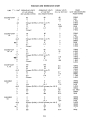
CHART that follows. A VOLTAGE AND RESISTANCE
CHART is also provided as
an aid in locating defective
components. DC operating voltages are given both at no
signal and signal developing 14 watts output, as well as
the corresponding 1 kc signal voltages.
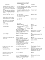
TROUBLE- SHOOTING PROCEDURES
Do not connect such a ground wire
to other components in the system If possible, let each
channel be connected to the amplifier using a separate
shielded cable to the ampl ifier input. It is also desirable
that the ground leads on both cables not be connected to-
gether at any point -
not even at the
cartridge. How-
ever, with some cartridges, it will not be possible to do
this. In this case, just disregard this last instruction.
Excessive hum on other inputs may be checked in a similar
manner. Disconnect the input cable in question and short
the particular input jack to the chassis. If the hum disappears, the trouble is external to the amp! ifier. Note
that on all inputs, the braid of th;;; input cable shou Id connect to the ampl ifier only through the skirt of the input
connector. The cause and remedies for the following
symptoms are then based on the assumption that checks
made in the manner described above have eliminated the
Connect the leads from the stereo cartridge and from the
two speakers to the amplifier.
as described in the section " Electrical Connections " . Set
the Input Selector control at PHONOand the Function Selector at STEREO. Playa known high quality stereo record-
.
possibilityof the trouble being external to the amplifier.
These connections are made
ing on the phonograph. If there is no output to the speaker
of if the output is low or audibly distorted , procede to the
checks for those symptoms. If there is excessive hum in
the output , disconnect the phono input cable from the
ampl ifier and short the phono input jack to chassis. If the
hum disappears, the trouble is not in the amplif.er but in
the phonograph or in the connection to the amplifier.
each case, check for the trouble in the amplifier which
seems defective. If both amplifiers are defective, check
the power supply.
The cause of phonograph hum may be a metal pick-up arm
not grounded to the cable shield (try a good single ground
connection to the cable shield from turntable frame, pickup arm, and cartridge case), direct hum pick-up by the
magnetic cartridge from the record player motor(tryusing
a rubber mat on the turntable to increase the separation of
If the trouble is no output or low output ,
check AC signal
voltages and DC operating voltages starting at the input
and work step_by-step toward the output in each ampl ifier. Set the VOLUME control to maximum (10), the
FOCUS, BASS and TREBLE controls to their mid- points
(0), the INPUT SELECTOR to PHONO and the FUNCTION SELECTOR to STEREO . Use a 1000cycle sinewave signal , such as supplied by the EICO 377 Sine &
In addition, use a precision 100: 1 attenuator to permit obtaining a level of
Square Wave Audio Generator
0035 volt fed into MAG. PHONO from an audio generator output of 0. 35 volts, which can easily be measured
onthelowestACvolts range ofyourVTVM (also improves
signal to hum from generator). Use a high input impedance VTVM for all AC signal voltage measurements; a
for DC volts measurements.
YOM
VTVM or 20, OOOQ/v
is an excessively distorted output, try tube
replacement, signal tracing, or procede directly to vol-
. If the trouble
tage and resistance measurements.
the pick-up from the motor), or pick-up from a power
transformer or other magnetic field in the vicinity (try
moving phonograph away from suspected source). Check
also that the phono input cable shielding is grounded to
the ampl !fier chassis at one point only, through the skirt
of the input connector where it plugs into the ampl ifier.
Finally, try a good building ground such as a connection
from a cold water pipe terminated under speaker terminal
When the defective stage is local ized, procede to a resistance and voltage check of the stage, using the data in the
VOLTAGE and RESISTANCE chart. Disconnect theampli-
fier from the power line and discharge capacitors prior to
making any resistance check and prior to removing any or
Do not turn the amplifier on
all of theEL84output tubes.
with any of the output tubes remove
CHECKING A TYPICAL TUBE STAGE
bass re- inforcement and the other bass cancellation. The
connection that gives bass re- inforcement is the in- phase
connection and should be used.
1. Check tube.
2. Check plate and cathode resistor.
3. Check coupl ing capacitors for leakage or short.
4. For output stage, check dc
Another criterion for the in- phase connection is that of
resistance of transformer
windings.
5. Check
blending, which can be best applied if the speaker systems
are identical or at least have similar middle and high
frequency range
grid leak resistor for open.
6. Check cathode by-pass capacitors for short.
B+ voltage on tube, check decoupling
low
no or
7. If
path for open or defective R60, R61, R62, R63 and fiI ter
capacitor C37, C38 or C39.
8. . If wiring and circuit components including the tube
voltage is excessive)' check the decoupl ing path for short or defective R60, R61, R62and R63.
reproducers. With the in-phase
con-
nection and both speakers operating at approximately the
same volume level, a monophonic source will appear to be
emanating from a point mid- way between and the two
speakers will blend. With the out-of- phase connection,
the two sources will appear to remain separate.
check O. K. and B+
Suspected trouble in the equalization)' tone, focus, and
volume controls and networks should lead to specific resistance and capacitance checks to localize the trouble.
In general, if the user suspects
defective equal
poor frequency response,
ization)' or defective operation of the tone
controls, the amplifier should be tested thoroughly
with
audio generator, vtvm, and scope.
SPEAKER PHASING
SERVICE
If trouble developes in your instrument which you
can;.,t
remedy yourself, write to our service department listing
all possible indications that might be helpful. If desired
you may return the instrument to our factory where it wi
be placed in operating condition for $12. 50 plus the cost
of parts replaced due to their being damaged in the course
of construction. NOTE: Before returning . this unit, be
sure all parts are securely mounted. Attach a tag to the
instrument, giving your home address and the trouble with
container)' using sufficient packing material (cotton, shredded news-
the unit. Pack very carefully in a rugged
IMPORTANT NOTE ON SPEAKER PHASING: The two
connected so that they operate.
in phase, meaning that corresponding cones or diaphragms
in the systems move in and out together when actuated by
loudspeaker systems must be
the same or similar signals. A simple method of checking
this is to playa conventional monophonic (lateral) recording having considerable bass program material, setting the
FUNCTION SELECTOR at MONAURAL. After listening
for a few minutes, reverse the connections of the speaker
paper, or excelsior), to make the unit completely immov-
able within the container. The original shipping carton
is satisfactory, providing the original inserts are used or
sufficient packing material inserted to keep the instrument immovable. Ship by prepaid Railway Express, if
possible, to Electronic Instrument Co., Inc., 33- 00 Northern Blvd., Long Island City I, New York. Return shipmentwill be made byexpress collect. Note that a carrier
leads at only one of the speaker systems - not both - and
cannot be held liable for damages in transit if packing
listen again to the same program
IN HIS OPINION)' is insufficient.
wi II noti ce that one of these
material. Normally, you
connections seems to give
TROUBLE- SHOOTING CHART
SYMPTOM
Amplifier causes power line fuse to
blow. Power line fuse blows again
with VII & V12 out of their sockets.
REMEDY
CAUSE
Line cord, J16, primary or high voltage Replace or repair.
secondary windings of T1 shorted internally
or externally (wiring).
VI0, or T2
Amplifier causes power line fuse to
blow. Power line fuse does not blow
again with VII & V12 out of their
sockets.
VII, V12, C39)' V7, va, V9,
Any or all tube filaments not lit.
Open tube fil ament.
Open lead from 6. 3V winding of T1.
Replace or repair.
T3 primary shorted internally or externally.
Replace or repair.
6 3 V winding of T1 open.
Output tube bias too high (resulting in distorted output waveform).
Open R56,
Replace or repair.
R57.
DC voltage at Vl1, V12 cathodes
(pin 3) is incorrect as specified
below.
a) No
voltage.
b) High voltage.
C39 shorted internally or externally.
Replace
Replace or repair.
Connection from C39 to pin 3 of VII
Repair
Defective VII or V12.
& V12 broken.
Connection to center tap of h. v. second-
Repair
ary winding of T1 open.
Output tubes V7, VS, V9, VI0 overbiased or not drawing current. May re-
shooting typical tube stage.
sult from open R56
c) Low voltage.
Excessive hum on mag. phono tape
head or mic.
Replace, repair, or see trouble-
or R57.
Excessive current drain in amplifier.
See trouble-shooting typical tube
Defective VII, V12.
stage.
Replace
VI or V2 defective.
Replace
FiI.
Dress fit. leads
leads dressed toa close to grid
away from grid lead.
lead.
Tube shield not making electrical con-
Check and correct.
tact to base or base not making electrical contact to chassis.
Shielding and grounding of wiring to
Correct
input jacks not exactly as instructed
and shown in drawings.
Excessive noise on mag. phono
tape head or mic.
VI and V2 and contacts dirty.
Clean throughly with carbon
tetrachloride.
Sustained oscillations.
Poor dress of output transformer T2 or
T3 leads.
Dress all input leads and T3 leads
away from each other. Keep T3
leads away from input jacks.
Sustained microphonicson mag.
VI or V2 defective.
Replace
V3 or V4 defective, not properly
Replace, correct,
phono, tape head or mi c.
Hum on all inputs.
shielded, or dirty sockets and contacts.
Dress of power transformer T1 leads.
Correct
or clean.
VOLTAGE AND RESISTANCE CHART
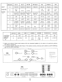
TUBE
PIN#
OPERATING VOLTS
AT NO SIGNAL
(DC UNLESS NOTED)
OPERATING VOLTS
AT 14W OUT
(DC UNLESS NOTED)
SIGNAL VOLTS
(1 kc) at 30W OUT
FROM POWER)
014
290KO
IMO
7KO
0035
290KO
90KO
2KO
CC83(12AX7
4&5
OHMS
UN IT DISCONNECTED
500
filament (OVDC; 6. 3VAC to pin 9)
500
filament
290KO
IMO
7KO
ECC83/12AX7
4&5
500
filament (OVDC; 6. 3VAC to pin 9)
290KO
90KO
2KO
500
fi lament
1. 2
ECC82/12AU7
V3, V4
. 1
4&5
500
filament (OVDC; 6. 3VAC to pin 9)
1. 8
1. 75
065
195
170KO
190KO
8KO
500
filament
ECC83/12AX7
120KO
61OKO
3KO
100KO
190
470KO
V5, V6
100KO
4&5
500
filament (OVDC; 6. 3VAC to pin 9)
1. 15
1. 1
7KO
500
filament
340KO
340KO
EL84(6BQ5
,1,
4&5
470KO
250KO
1650
14.
12.
filament (OVDC; 6. 3V AC between pins 4 & 5)
500
330KO
335
325
180
165 1900
330KO
330
3500
320
340KO
340KO
EL84(6BQ5
12.
4&5
-,7
14.
03*
6 2
335
325
330
320
1650
500
filament (OVDC; 6. 3V AC between pins 4 & 5)
180
330KO
330KO
3500
EL84/6BQ5
V9, V10
0 6.
7
12. 7 14.
. 03 *
4&5
EZ81/6CA4
VII, V12
4&5
filament (OVDC; 6. 3VAC between pins 4 & 5)
335
325
330
320
290 V AC *
29OV AC*
180
340 335 7.
290*
filament (340VDC; 6. 3VAC between pins 4 & 5)
290V AC *
290V AC *
290*
340KQ
340KQ
165Q
50 Q
165- 190 Q
330KQ
350Q
45- 55 Q
100KQ
100KQ
45- 55 Q
* = 60 cycles
All resistance measurements, except those made from pin 3 of Vl1 and V12 (EZ81 rectifier), are
made with pin 3 of V11 and V12 grounded. All voltage and resistance measurements are measured
to chassis with the controls set as follows: INPUT SELECTOR to PHONO, FUNCTION SELECTOR
to STERO NORMAL)' LEVEL at 10, BASS, TREBLE & FOCUS controls at O. For voltage measurements
at 14W output, set the input selector to the PHONO position and feed a O. 0035volt (;3. 5mv) 1 kc
signal to the CH 1 & CH 2 Mag. Phono Input jacks; connect a resistive (preferably non- inductive)
load to the output of each amplifier, of equal resistance to the tap selected (::1:20%), and capable of
handling 15 watts. Voltage measurements are made with a VTVM. Operating line voltage atwhlch
voltage measurements are made is 117VAC, 60cps. NOTE: ALL VOLTAGE & RESISTANCE VALUES
NORMALLY BY::I:15%.
AUXA
SECTION
AM-FM
AUX B
FM-MUL TI
PHONO
MIC
TAPE
INPUT
SELECTOR
11-
11-
SWITCH
2-6-
S 1
10- 11-
10- 11-
10-
10- 12
10- 11-
10- 113- 7
4-11
1 -4-
2-4-
3-4-
10-
10-
10-
3-610- 12.
10-
1":12
10-
10-
SECTION
10-
10-
AMPL. 2
AMPL. 1
10-
9- 1 0-
NORMAL
10-11
TUNER AUX.
REVERSE
PHONO
FUNCTION
SELECTOR
SWITCH
3-4-7
4- 10
1) Entries are numbers of those switch contacts which are connected together by the rotors at the particular position.
NC means no connection.
2) On schematic diagram, all switch wafers shown in the maximum counter_ clockwise position (AUXA and CH 1CHECK)as
seen from the front or shaft end.
TOP VIEW
~~L~~/6BQ5 ~~~84/6BQ5
OPERATES FROM ""V
~'-'t'~
SO/6C CYCLE AC LINE
ECC83/12AX7
84/6BQ5 ~~L~4/6BQ5
MODEL HFDUAL 14 WATT HIGH FIDELITY
INTEGRATED AMPL"'ER
ECC83/12AX7
r'\
V V
r'\
ECC83/12AX7V ECC82/12AU7V
r'\ V-
POWER CONSUMPT'ON.
140 WATTS
ELECTRONIC INST. ' CO.. INC.
r'\ VECC83/12AX7
r'\V-
noo NORTHERN BLVD
r'\V- 11
L , CITY 1 N Y
r'\V-
VEZ81 \JEZ81
VECC82/12AU7
FRONT
AUX A
iUEIiJ.
MODEL HF-
AUX B
DUAL 14 WATT HIGH FIDELITY
INTEGRATED AMPLIFIER
3 AMPS
117 VAC
(Q) ITJJ
SPEAKER CONNECTIONS
TAPE OUT
CH- 2
CH.
OAM MULTIO
10 0
0 001 100000\
CHANNEL 2
CHANNEL 1
OFM
000 000
MIC PHONO TAPE
CHANNEL 1
MIC PHONO TAPE
CHANNEL 2
REPLACEMENT PARTS LIST
Stock'
20050
23014
23020
22517
22514
22518
22550.
22506
20039
22520
22529
22543
23007
22533
24005
23016
20043
22519
91005
92000
50020
50018
Description
Stock'
Cl,
cop. , paper
~1\T
C3,
C5,
C7,
cap., disc., . 025mfd, GMV (25K or 25, OOOmmf)
Symbol
25mfd, 200V
cop., elec., lOmfd, 6V
cap., elec. , 25mfd, 6V
33,
C35, 36, 45, 46
C9,
Cl1,
C13,
C15,
CI7, 18, 21,
CI9, 20, 41,
C23,
C25, 26, 27, 28
C29,
C31, 32, 43, 44
C37
C38,
C40
C47, 48
cap., disc., 850mmf, "'10%
cap., disc., . 0027mfd, "'10% (2. 7K or 2700mmf)
cap. disc., 6oommf, "'10%
(20K or 20, 000mmf)
02mfd, "'10%
cop. disc.
cap., molded,. lmfd, 400V, "'10%
J14J16
PCl,
Rl,
R:r,4, 40, 41,
53, 54,
11526
10423
10430
11504
11527
RS, 6, 11
10422
11518
_18045
---., 8046
10435
10414
18048
18047
10410
10420
R13
R15,
RI7 18, 44, 45,
46,
R19 20, 60
R2I,
R22, 23
R24, 25
R26,
R28, 29
R30,
R32, 33, 54
R34, 35, 68, 69
10431
R36,
R38,
11543
10412
R48, 49, 50, 51"
14600
11538
10851'
10952
14302
19009
10421
R42, 43
RS6, 57
RS8, 59
R61
R62
R63
R64
R70, 71
nut, for fuse holder
jack, dual
outlet, convenience
printed circuit
res., IMQ, 1/~, "'10%
res., 10KQ
(brown, black,green, silver)
1/~, "'10% (brown, black, orange, silver)
res., 200KQ, 1/~, '" 5% (red, black, yellow, gold)
(red, red, red silver)
res., 2. 2KQ, 1/'NI, "'lOOk.
res., 4. 7KQ, 1/~, :10% (yellow, vi~let red, silver)
5%
(white,
black, orange, gold)
res., 90KQ, 1/'NI
res., 100KQ 1/'NI, '" 5% (brown, black,yellow,gold)
res., 68KQ, 1/'NI, :10% (blue, grey, orange, silver)
res. , 2.2MQ, l('NI, : 5% (red, red, green, gold)
pot. , 750KQ linear, dual
TB5
TBIO, 19
TBI2, 14
43004
46000
46006
50012
50019
nut, he", '4-40
nut, lin., '8nut, tin., angle bracket
screw, '6- 32 x 1/4
screw, '8- 32 x 3/8
screw, '4- 40 x 1/4
screw, '4-40 x 1/4 brass
screw, '4 wood
screw, '8- 32
x 1
screw, '6 P. K. brown
screw,
'8- 32 brown
screw, '8 P. K.
washer, '3/8 lock
washer, '6 lock
~sher, '4 lock
washer, '8 lock
washer, rubber, forfuseholder
washer, fiAt, '8
lug, '6 ground
lug, '3/8 pot ground
lug, 18 ground
grommet, 3/8
feet, rubber
insulator for 50011
insulator for 50018
insulator for 50020
pbono plug
knob, outer concentric
50021
51006
53016
pot., IMQ, linear, concentric
pot. , 500KQ, linear, concentricw/SPST switch
res ", 100KQ, l(ZW, %10% (brown, black, yellow,
53017
53018
57000
58004
58300
58302
58408
58410
58412
knob, inner concentric
58501
80057
81109
81110
81111
81116
81124
wire, bare
silver)
res., I. 8KQ, 1/~, :10% (brown, grey, red, silver)
silver)
res., 3. 3KQ, l(~, %10% (orange, orange, red, silver)
res., 470KQ, 1/~, :10% (yellaw, violet,yellow, silver)
res. , 1.8KQ, l(~, : 5% (brown, grey, red, gald)
res. , 330KQ, 1/~, :10% (arange, arOnge, ye ilow, sHver)
res., 1650,
!)N, % 5%
res., 22KQ, 1/~, % 5% (red, red, orange, gold)
%10"k. (red, red orange, silver)
res., 22KQ, lW,
res., 4. 7KQ,~, :10% (yellow, violet, red, silver)
res., 3500, lOW, :10%
pot" 100Q
res., 6. 8KQ, 1/~, :10% (blue , grey, red, silver)
30021
TB6,7, 13,
TB9, 11, 18
43001
nut, hex, '6nut, hex, '3/8-
pot., 250KQ, audio, dual
res., 150KQ, 1/~, :10% (brown,green,yellow,
transformer, power
transformer, output
T84
fusebolder
pilot assembly
sacket, 9 pin min. w/shield
socket, 9 pin min.
nut, he", '8-32
switch, Input Selector
switch, Function Selector
switch, slide, DPDT
switch, slide, SPOT
T2, 3
TB1,
TB3,
XFl
XII
XV1, 2, 3,
XV5, 6, 7, 8,
10,
40016
40026
40027
41000
41003
41016
41026
41027
41028
41045
41046
41047
42000
42002
42007
42008
42029
42032
43000
cap. , elec., 4O- 40- 20mfd/350- 350- 400V
cap., elec., 30mfd, 4O0V
cap., molded, .03mfd, 600V
(10K or 10, 000mmf)
cap., disc., . 0Imfd, "'10%
60057
60065
62000
62002
32013
54516
54002
54001
54014
54003
54006
54013
54008
tube, EL84
tube, EZ81
Vll,
40008
jack, triple
10407
10400
tube, 12AX7
tube, 12AU7
V7, 8, 9,
cap., disc., 47mmf, "'10%
11- 1250011
Vl,
40000
40001
40007
10.
50016
"'" 29751
terminal strip, 2 past right
terminal strip, lP left
"'10% (1.2Kor 1200mmf)
cap. disc., 150mmf, "'10%
cap., disc., 225mmf, "'10%
cap., elec., 5Omfd, 25V
pilot light, '47
jack, quad,
J5-
...97025
cap., disc., . 0012mfd,
fuse, 30mp
JI-
54000
90034
90033
90039
90038
97800
97712
97027
Description
TB15,
TB17
terminal board, 5 screw
terminal strip, lP right w/ground
terminal strip, IP right
terminal strip, 3P 2 left
terminal strip, 2 past
terminal strip, 3P 2 right
terminal strip, lP left w/ground
terminal strip, 4 past
81134
81144
81145
81146
81154
81903
89207
89208
89219
97300
97710
66067
66316
knob, duell concentric
line cord
wire, hook...p, thin wall
spoghetti
spaghetti, heavy
cable, 1 conductor
cable, 4 conductor
cable, 3 conductor
panel
bottom plale
brocket, left
bracket, right
bezel
chassis
shield w/spade bolls
perfomled screen
bracket~ Input
bracket far DPDT switch
shield bottom
clamp, wire
label, rear apron
label, tube layout
label, service
tube shield
Jewel, red
manual af instructions (wired)
manual of instructions (kit)
length
length
length
length
length
length
length
Jl1
J12
J13
Jl0
""1:26
""C25
-C23
~C24
-C22
.....C21
--C20
--C19
-CJ8
,...CJ7
-'J6
-CJ5
........C14
-c13
..:.CJ2
- ClI
=CIO
~C8
.... C7
....c6
-c4
... Cl
';'",,-,
C28
200V ~
6V
6V -
200V "'- C27
C13
~'4
%10% -:13
%10% -
cap., disc., 150mmf,
cap., disc. , 225mmf
cap., disc., 225mmf
%10% _
%10% '
cap., molded, . 1 mfd, ..uJOV, %1O%-"'C48
-Jl
cop., disc. , 150mmf
%10%
%10%
GMV %10%
6V
6V
GMV
cap., elec., 10mfd
C29
cop., elec., IOmfd,
,.-C30
cap., elec., 25mfd
"'C31
cap., elec., 25mfd
;;,-C32
cap., disc., . 025mfd
,C33
cap., disc., . O25mfd,
C34
cap., disc., 850mmf,
""C35
cap., disc., 850mmf, %10% . C36
cap., disc. , . 0027mfd, %10% ;"C37
cap., disc., . 0027mfd %1O% ...C38
cap., disc., 600mmf, %10% ......c39
cap., disc., 600mmf %10% .....,('C..uJ
cap., disc. 02mfd
-C41
cap., disc., . 02mfd,
"..,c42
cap., molded, . Imfd, ..uJOV, %IO%-C43
cap. molded, . Imfd, ..uJOV, %IQ%- C44
cap., disc., . 00J2mfd, %IO"k .?C45
cap., disc. OOJ2mfd %10% "C46
cap., molded , . I mfd, ..uJOV, %1O%-C47
cap.,paper, . 25mfd
cap.,paper, . 25mfd
Description
, .
, .
';'
RI3
R12
RlI
RJO
R2l
R19
R20
R32
R33
R34
R35
R36
R37
R38
R31
--R30
res., 3. 3KQ I/2N, "'lO"k
res_, 470KQ, I/'M, "'IO%
res., 150KQ,I/2N, "'10%
res.,
8KD.I/2N,
"'10%
res., I. 8KQ,
%10%
I/2N,
pot. , IMQ, linear, concentric
pat., lMQ, linear, concentric
pat. 500KD. linear, concentric
, concentric
pot., 500KQ, linear
res., lOOKD. I/2N "'10%
res. , lOOKD. I/2N, "'10%
res., 3. 3Kn, I/2W, %JO%
R28
R29
res., 150KQ,I/2N, %10%
R27
pat., 250KQ, audio, dual
pat., 250KQ, audio, dual
R26
--rt25
R23
R24
res., 68KQ, J(2N,
:10%
res., 2MQ,J(2W, :5%
pot. , 750KQ linear, dual
pot., 750KQ linear, dual
res., 100KQ,I/2W, % 5%
res., 68KQ, I(2W, :10%
res., lOOKQ,I/2N, % 5%
R17
RJ8
res., 9OKD. J(2W, % 5%
4.7KD. I/2N, %10%
res. , 9OKD. I/2N, % 5%
Descri tion
res.,
R71
R16
RJ4
RJ5
;:.oR22
-';'
=-R63
R62
R61
R58
R59
R60
- R57
-R56
R52
R53
R54
R55
R51
R42
R43
R44
R45
R46
R47
R48
R49
R50
R4l
R..uJ
R39
I/2N, %10"k
7KD.
res., 350Q,
res.,
res., 68KQ,
res., 22KQ,
--VI
.......VI2
-VIO
....VII
-V9
-V8
""V7
"-...V6
.V5
... V3
-55
12AX7
12AX7
12AU7
12AU7
12AX7
I2AX7
tube, EZ81
tube, EZ8J
tube , ELM
tube, ELM
tube, ELM
tube, ELM
tube,
tube,
tube,
tube ,
tube,
tube ,
switch, input selector
switch, function selector
switch, slide, DPDT
switch, 5P5T, port of R32,
switch, slide, 5PDT
res. , 6.8KQ, 1/2N, :10%
res., 2. 2MQ, I/2W, % 5%
res., IOOKQ, I/2W, :10%
:10%
res., 6, 8KQ, I/2W, :10%
res., 1O0KQ, I/2N,
res., 330KQ, I/2W, %10%
res., 330KQ, 1/2W, %10%
pat., 1O0Q
Description
C18
R32
(g)
1958
R61
R62
JI5
JI4
R63
..1f37C ..1f378 .1f37A ..1f38
R60
'IV
STEREO AMP. PREAMP
lOW, %10%
I/2W, :10%
IW, :10%
I/'M, :10%
165Q, !NI,
5%.
res., 165Q, !NI,
res. , 22KQ, I/'M, % 5%
res. , 22Kn, I('M, % 5%
res. ,
res., 10KD. I/2W, %10%
res. , lOKn, I/2W, :10%
res., lOKQ,
res., 33OKQ, 1(2W, :10%
res. , 330KD.J(2W, "'10%
res., 1OKD. J(2W, "'10%
res., 330KD. I/2W, :10%
res., lOOKD. I/2W,% 5%
res. , 330KQ, I/2W, :10%
-51
R71
res., 100KD. I/2W, : 5%
res., 100KQ, I/2N,
res., 1. 8KD.I/2W, %5%
res. , 100KQ, I/2W, : 5%
R66
R64
R65
5ym
R67
R68
R69
R70
470KD. I/2W, %10%
res., lOKn, J(2W, %10%
res., 10KQ, I/2W, %IO"k
res., 1, 8Kn, I/2W, % 5%
res"
Description
4"5
DUAL 14 WATT HI-
res., IMQ, I/2N,
%10%
res. , JMQ, I/2N; %10%
res., 200KQ,I/2N, % 5%
res., 200KD. I/2N, % 5%
res.
7KD.I/2N, %JO%
res., 2.2KD.I/2N, %10%
res. , 200KD.J(2N, % 5%
res., 2Kn, J(2N, %10%
res., IMQ. I/2N,
%10%
res., JMQ, I/2N,
%JO%
res., 1OKD. I/2N,
%10%
res., 10KD. I/2N,
%10%
res., 200KD. I/2N, % 5%
ac pawer
tope output - channel I
-116
tope output - channel 2
:)15
phono - channel I
tope - channel I
mic - channel.
phono - channel 2
tope - channel 2
mic - channel I
multiplex
aux A - channel 2
DUX B - channel 2
DescriJ'tion
"JI2
JI3
..J14
,-:Ill
"JI0
d'l
~~~
MODEL Hf-
%10%
aux A - channel I
aux B - channel I
cap. , disc.. . 0Imfd
cap., disc. , . 00 12 mfd, %10%
cap., disc. 0012mfd %1O%
cap., disc. , 47mmf, %JO%
cap., disc. , 47mmf, %10%
cap., disc., . O25mfd, GMV
cap., disc., . 025mfd, GMV
cap., disc., . OJ mfd, %l0%
cap., elec., 40-40-20mfc!/350-350-400V
cap., elec. , 30mfd,..uJOV
cap., elec., 3Qmfd,4OQV
cap., molded, .03mfd OOOY
cap., disc., 47mmf, %10%
cap., disc., . 025mfd, GMV
cap., disc., . 025mfd, GMV
cap., disc., . 025mfd, GMV
cap., disc., . 025mfd, GMV
cap., disc., 225mmf %JO%
cap., disc., 225mmf, %IO%
cap., elec., 50mfd 25V
cap., elec., 50mfd, 25V
cap., disc., 47mmf, %10%
Description
';'
R42
VllVI2
----
C32
R58
C31
R59
';'
';'
su!d ta)j::Jos aljt Ot 6UHJoljS lOt
uapp::Jo tuaAaJd Ot S!ssolj::J aljt pJOMOt sta)j::Jos aljt uo sqOt 6nl punoJ6 aljt puas
Japlos puo pauuo::J suoaw (S) UOHO!AaJqqo
(papauuo::J uaaq aAolj spoal Jaljto I!tun) Japlos taU op tnq pauuo::J suoaw
alj1 :atoN ' paH!WO aq AOW sl!otap 6UP!M JO 6uHunow jO
~l
(j) UOHO!AaJqqo
%OZ
(~W) wlj06aw L :: (~)I) swljolPI
swljo
OJ::J!W-OJ::J!W
OOOL
(jW) SpOJOj OJ::J!W L ::: (jww) SpOJDj
000 000
000 000
uo!wadaJ AJOSsa::Jauun I papMoJ::Juns6u!MOJpalj t d3a)j01 ' sMollOj ampa::JoJd 6u!
J!M puo 6uHunow datS- Aq-dats ataldwo::J aljl :3~nG3)0~d NOI1)n~1SNO)
SJots!saJ
'AtPodo::J JO a::JuotSlsaJ ssaJdxa Ot pasn sHun aljt uaaM,Jaq sd!ljsuoHolaJ
6U!MOIIOj aljt atOU asoald ' patupd san loA J!aljt aAOlj SAOMIO II!M S::JHAloJpala
puo SJOH::Jodo::J ::Js!pSOaJaljM ' papo::J JOlo::J aq tau AOW JOAOW SJOt!::Jodo::JJolnqnt
parlow tOljt oslo ~patu!Jd sanloA J!aljt aAolj Jots!saJ %L SOaJaljM papo::J JOlo::,
puo ' %OL
aJO
tDljt PU!W U! daa)j ' UOHo::J!jHuap! p!doJ U!
auo Ot lonba S! (jw) pOJOjOJ::J!W auo
sato::J!p
patu!Jc.:
U! anloA aljt U!Otqo Ot
tsnw anloA 10::J!Jawnu patupd aljt toljt
SpOJOj OJ::J!W- OJ::J!W JO swljo
P!O 01 ' (jww) SpOJOjOJ::J!W- OJ::J!W ~uo!lI!W
toljt oslo alaN 'AlaA!padsaJ
puosnoljt dUO Aq pa!ldHlnwaq
S! )I Jattal aljl '
AJaA
tDljt atou asoald :NOll
JO
V')I:lIlN301 Sl~V'd
.
sJa!ld soD '
.
U!SOJ AHlonb lj6!H
atsod JO P!::Jo
Jaddpts aJ!M 0 puo sawu!ds jO tas V'
oslo
xnH ::JHaljtUAS tualoA!nba
sa::JuOtswn::JJp AUO Japun xnH
aJO
AJaA
J!aljt aAoljtnq I papo::J JOlo::J aqtO UAoW uaA!6 S! 6u!po::JJO\0::J
U! SjOH::Jodo::J JO SJots!saJ uo puo (OOOLX) JalldHlnw 0
s6UHOJ puosanloA
Injasn
aJo::J
lj::J!ljM JOj stJod aljt jO AUOW
SIOOt AJotuawalddns
asn Wu 00 . Japlos
aJO
sloat ::J!soq asalj1 :G3~lnO3~
51001
)ISV'S
. Jalj!ldwo aljt jO
9 JO t;; - sJa!ld asou6u01 .
apolq ,, 8/L - JaAppMaJ::JS
apolq " V/L ot 11 9L/~ - JaAppMaJ::J5 . L
SJaHn::J lou060!0
(SHOM ~~) UOJ! l!::Juad JO ' un6Japlos JO ' (SHOM OOL) UOJ! 6upaplos
uo!pnJtsuo::J aljt JOj paJ!nbaJ
aq
tUIO! 0 JaplosaJ O~ AJOssa::Jau sl t! UOSoaJ AUO
sWOJ6OIP aljt U! UMOljS so patnOJ SI peal aljt ualjM ljt6ual paJ!nbaJ
aljt paulWJatap aAOlj nOA IHun peal AUO tn::J tOU 00 'AJOssa::Jau ualjM ljt6ual
aJO
JadoJd ayt Ot paWwpt aq PlnoljS spoal asalj1 ' paJlnbaJ UOljt Ja6UOI uauo
SJaWJOjSUOJt pUO ' SJOH::Jodo::J ' SJOts!saJ uo spoal aljt tOljt patou aq oslo Plnoljs
. JaplOS Mau asn ot aJns
tuauodwo::J aljt tuaAaJd pUO AOMO toalj
ljHM paJap
SJaiid alj1 ' SJalld asou6uol jO Jlod 0 jO dH aljt
JOj jl ' patOaljJaAO Alnpun 6u!aq WOJj
aljt pnpuo::J 111M
-IOS 6u!aq tU!o! aljt puo tJod aljt uaaM,Jaq
peal aljt Plolj
tJod 0 Ot
asol::J 6upap
-IDS am nOA jl ' UMOP )joaJq JO '6uHOO::J aAlpatoJd Jlaljt asool l anlOA a6uolj::J
JaljHa AOW H Ot papauuo::J StJod aljt
tUIO! 0 Ot pal Iddo S! toalj lj::Jnw oct
puolj Jaljto aljt uo . AJOPOjSHoSun S! lj::JIljM tU!oJ UISOJ 0 6UHo::J!PUI ' AaJ6 puo
3~0) ODV' 35n 53)
pamdJoaddo II!M tU!o! aljt ' pa!lddns S! toalj aitHI OOt jl ' toalj lj::Jnw oct puo
toalj alH!I OCt ~pap!OAO aq Ot sawaJtxa OM,J aJO aJalj1 . paloo::J solj Japlos aljt
ualjM AU!ljS puo ljtoows S! tU!o! 6uHI nsaJ aljt toljt adS Ot )j::Jalj::J pUO SMOlj Japlos
aljt IHun UOJ! 6upaplos aljt aAOWaJ tau 00 ' jlasH tUlo! aljt WOJj toalj aljt Aq
patlaw SI Japlos aljt tOljt os(UOJ! aljt uo tou) tU!oJ aljt uo Japlos aljt a::Jold puo
SttOM OOL uoljt Jallows ou ' uoJ!6upaplos pauuHAlljsaJj ' uoal::J 0 asn ' uo!pau
jO u!otJa::J 0 a)jow 6upaplos aJojas ' UO!SOJJO::J snop
ppo a::Juls Xn1:1 01:)"'1' ~O ~3G10S
-uO::J 10::J!uolj::Jaw po06 0
-as asno::J UO::J xnlj
~3G10S 3~0) NISO~ ::10 30V'~D 153S 3H1 3Sn
AlloHUOtS
%O~-
:SlNIH NOI1)n~lSNO)
NV'1SWn)~I) ON ~30Nn ' sadApollwIs JO " aJo::JHlnw" U!SJ3 ' " aAI:I-u!sa~"
Jatsa)l so lj::Jns saxnH patOA!pO Mau aljt 6UIU!Otuo ::J dUO AlqOJajaJd
1NO
puo %OOL+ Allonsn S! S::JHAloJpala JOj a::JuoJalot aljt puo ' JatoaJ6
'Ins aJO SJOH::Jodo::J
II!M tuauodwo::J 0 jO anloA aljt
toljt pu!j II!M
noA
Jadod uo sa::JuoJal01 . ~)lZ' ~ puo ~)lZ' V uaaM,Jaq aJaljM
I ~)lL' aljt ' aldwoxa Jo:l ' a::JuoJalot t!n::JJ!::J
AJOA
AUO aJnsoaw AOW Jots!saJ%OL =F
alqoMollo aljt U!ljHM
tJolj::J r-
ape:;. JOlo::J aljt JO SWOJ6OlP 10pop!d aljt Ot JajaJ StJod AUO 6U!AjHuapI alqnoJt
aJO
aAolj noA jl ' S!ssolj::J aljt Ot patunow
toljt stJod asolj t 6u!pnl::Ju! ts!I stJod aljt
tSUl060tJod lj::J09)j::Jalj::J puo AI InjaJo::J t!)j aljt )j::Jodun :1()I 3H1 DNI)I)V'dNn
UMOljS tnoAol s.llod puo aJ!M aljt 6u!MOIIOj aljt Aq pa::JnpaJ
joAtln::J!H!paljt puopaAoJdw!aq II!M tuawnJtsul
aq II!M JOJJa 6U!J!M 0 6UlpU!j
pataldwo::J aljt jO a::JuoJoaddo aljt Alu!opa::J puo l uosoaJ po06 0 JOj UMOljS so
aJO
saliM uatjO AJaA ' alq!ssod so Alasol::J so SWOJ60!p 10!Jop!d aljt U!
pa::Jold
UMOljS tnOAol StJod pUO aJ!M aljt MOllOj nOA tOljt AI6UOJtS a6m aM aJoWJaljtm::l
. 6UP!M puo Alqwasso JadoJd JOj
tOU Ot nOA a6Jn aM
ale)
uoH::JnJtsuo::J aljt ljsnJ
tnq
Uo!pnJtsuo::J aljt U! ua)jot
Amssa::Jau awH aljt 110 a~ot Ot
pJOMaJ II!M tuawnJtSU! slljt jO
puo a::J!AJas AJOPOjSHOS jO SJoaA AUOW ljHM
JopnJtsuo::J aljt
. tuawnJtSU! S!lj Ul a::Juapuuo::J JatoaJ6
H SMOllOj puo H sapa::JaJd ljtoq toljt uolpas NOll
-)n~1SNI aljt 6ultdnJsap tnoljHM paAOWaJ aq AOW puo )jooq aljt Ul AlloJtua::J
pato::Jol SI Uo!pas NOIl)n~1SNO) aljt toljt atON ' uoH::Jas NOI1)n~15NO)
aljt 6UIMOilOj sa60d aljt uo sawnsaJ uolpas NOI1)n~15NI alj1 ' ('::Jta ' )2:
),, Aq paMolloj sJaqwnu a60d aAolj Uo!pas S!ljt U! sa60d IIV' ' uolpas
)L)
NOIl)n~15NOJ aljt S! a60d S!ljt ljHM 6uluu!6aq lonuow aljt jO Uo!pas alj1
SNOUJn'H.1SNI 'V'H:lN:I!)
to.)
-$-
TBll
XVll
XV12 -
TB21
TB20
8'
'-'. ) !'
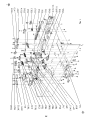
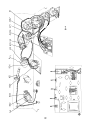
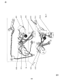
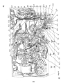
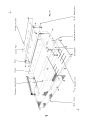
Fig. 1
XV6
TB3
.J8910
-Jl11213
XV8
TB2
TB1
TB4
TB17
TB13
TB5
TB18
TB 14
XV9
XV10
TB19
-$-
addition to Fig. 1,
it will be required to refer to Fig. 6 in the fol-
j9 direction in figure 6.
chassis and the input
jack strip. (Fig. 10).
screws, two #4 lockwashers and two
hex nuts.
Fig. 1. Mount the
shown.
hex nuts.. Mount a
lockwashers, mount one post right terminal strip, TB4.
5 screw terminal board, TBl, as shown. Use two
#6- 32 screws, two #6 lockwashers and two #6- 32 hex nuts. Under one of the
8. ( J)
2 hole insulator between the chassis and the jack strip.
Use four #6- 32 screws, four #6 lockwashers and four #6- 32
7. (~) Fig. 1. Mount the2 terminal tape output jack strip, J14, 15, QS
and tWo #6- 32
6.
1. Mount the switch bracket with the switch (previously mounted
il6
lockwashers
in step 5) on the chassis, as shown. Use two #6- 32 screws, two
(~ig.
#4-40 hex nuts.
two #4-40
1. Mount the double pole 2 position slide switch, S3, into the
switch bracket, as shown. Use
5. . ('
~i9'
washers and four
16- 32 hex nuts. Mount a 3 hole insulator between the chassis
and the input Jack strip. (Fig. 10)
1. Mount the 3 terminal input jack strip, JIl)' 12, 13, as shown.
Note mounting direction in figure 10 Use four '6- 32 screws, four #6 lock-
4. (J, Fig.
the
Fig. 1. Mount the 3 terminal input jack strip, J8, 9, 10 as shown.
four #6- 32.screws, four #6 lockwashers and four #6- 32Iiex nuts. Mount
(J)
Use
the 3 hole insulator between
3.
XV5, XV6, XV7, XV8, XV9 and X\f10. Use two 14-40 screws, two #4 lockwashers, and two #4-40 hex nuts on each. In each case)' note the mounting
direction in figure 6.
2. (/) Fig. 1.. Similar to the above, mount 9 pin miniature sockets, XVII,
mounti
v(
Fig. 1. Mount the 9 pin miniature tube socket, XV12, as shown. Use
two #4-40 screws, two #4 lockwashers, and two #4- 40 hex nuts. Note the
lowing mounting procedure in order to settle such matters as orientation of
terminal boards, keyways on tube sockets, etc. The wiring which comes later
will be greatly facilitated if, after mounting each part, the symbol number of
the part is written on the bottom of the chassis next to the part with a crayon
soft pencil.
Note: In
BELOW CHASSIS ASSEMBLY
1. Mo,nt
the 5
wew
te,mlnall"""d, TB2, '" ,hawn.
U,e two
Fig. 1.
Fig. 1. Push a rubber grommet into the 3/8"
hole next to the fuse-
(I)
Fig. 1. Mount
3/8
this manner are: three post , two left ,
TB5; two post , TB6;
)' F"
Fig. 1. Mount the
#6 ground lug " G" with one #6- 32 screw,
Note position of lug on figure 6.
one
1. Mount the single pole 2 position sl ide switch, S5, as shown.
screws, two #4 lockwashers and two #4- 40 hex nuts.
#6 10cKwasher and one #6- 32 hex nut.
18. (
Use two \4.-40
17. (,
four pos~, 1814; one post left, TB 17; three post, two right, TB 18; one post left
with ground; TB19; on~ post right with ground, TB20, and two post right , TB21.
two post, TB7; two post , 188; three post, two right , TB9; one post6 1eft with
ground)' TBI0; three post, two right, TBIl; four post, TB12; two post, TB13;
to be mounted in
16. (\4 Fig. 1. Mount the following terminal strips as shown. Use one #6scre ;J;/)one #6 lockwasher and one #6- 32 hex nut on each. The terminal strips
this terminal.
up the lu ~ with terminal 2. The grounding lug
will eventually be soldered to
hex nut. Between the
potentiometer and the
When tightening potentiometer, line
hum bucking potentiometer, PM, as shown. Use one
Je one 3/8 pot ~rounding lug.
chassis, u
3/8" lockwasher and one
15.
14.
Fig. 1. Mount the 30mfd, 4O0V electrolytic capacitor, C39, as
shown. Use one #6- 32 screw, one #6 lockwasher and one #6- 32 hex nut. Note
direction of positive side. (It is the reverse of C38 in step 13 above.
13.
Fig. 1. Mount the 30 mfd, 400 V electrolytic capacitor, C38, as
shown. Use one #6- 32 screw, one #610ckwasher and one #6- 32 hex nut. Note
direction/of positive side.
th
1. Mount the convenience outlet, J16, as shown. Use two #612.
screws, (two #6 lockwasher and two #6- 32 hex nuts.
holder.
11.
nut.
against the outside of the chassis under the
10.
Mount the fuseholder, XFI, as shown. Use rubber washer
wider part of the holder. Slide the
large nut over the fuseholder on the inside of the chassis. DO NOT tighten
maining "nut, mount a #6 ground lug.
#6- 31hlg.screws, two #6 lockwashers and two #6- 32 hex nuts. Under the lockwasher, mount one post right with ground terminal strip, TB3. Under the re-
9.
j,
~g.
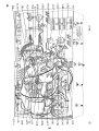
PREWIRING OF SELECTOR SWITCH
(C) to S 1 B- 7 (S 1).
Connect C46 from S IH- 7 (C) to
/J)
G- (S4).
3/)ft.
:Sf)
(C).
to S 1 G- 1 (S2).
Fig. 2. Cut all leads on two 47mmf disc capacitors, C43 and C44,
Connect C43 from S 1 B- 12 (S2) to S lC- 12 (S2). Connect C44 from
(C) to SlG- l
SlG- 5 (Sl) to SlF- 5 (C).
8. ( /Fi9. 2. Cut all leads on two 600mmf disc capacitors, C13 and C14,
to 3/4" . Connect C13 frcm SlB- 4 (Sl) to SlC-4 (C). Connect C14 from
S 1 F-
to
7.
Connect;R18 from SlF- l
6. (' Fig. 2. Cut all leads on two 100KQ (brown, black, yellow, gold)
resistors)' R17 and R18, to 1/2" . Connect R17 from SlB- 12 (C) to SlC-12 (C).
to S 1
tors, Cll and C12, to 1/2" , Cover each lead with a 1/4" piece of spaghetti.
conne t 111 from SlB- l (54) to SlC- l (S2). Connect C12 from SlF- 2 (S2)
disc capaci-
(C). Connect
5. (~ Fig. 2. Cut all leads on two. 0027mfd (2. 7Kor 2700 mmf)
R67 ftm SlF- 2 (C) to SlG- 2 (C).
(C) to S lC- l
two 2. 2MQ (red, red, green, gold) 5% resistors,
Connect R21 from SlB- l
Fig. 2. Cut all leads on
R21 and R67, to 1/2" .
4.
(S2).
850mmf disc capacitors, C9 and C10, to
(C).
(S2) to SlB- l (C). Connect CI0 fromS 1 G- 2(C)
2. Cut all leads on two
Connect C9 fromS1B- 3
to S 1/-4
3/4" .
3. (d. Fig.
resistors, R15 and R16, to 1/2" . Connect R15 from SlB- 3 (C) to SlB- l
Conne R16 from SlG- 2 (C) to SlG- 4 (C).
2. ()) Fig. 2. Cut all leads on two 90KQ (white, black, orange, gold) 5%
Connect C45 from S IB- 6
S 1 ~ /S 1).
1. 4) Fig. 2. Cut all leads on two. 025mfd(25Kor 25, 000mmf) disc capacitors, C45 and C46, to 3/4" . Cover each lead with a 1/2" piece of spaghetti.
num er. The lug is re ferred to by the wafer number and lug designation. Thus
lug lD- 3 refers to selector switch S 1, the " D" side of the wafer (rear side of
the econd wafer-side facing you when holding the switch as shown in the drawing) and 3 refers to the lug on this particular side of the wafer.
determined by looking at the switch from the view shown in the figure. Each
side of the wafer has been assigned a letter. Each lug has been assigned a
Turn the switch to its maximum counter-clockwise position. The switch is shown
in the figure from the rear view. The exact position of the lugs referred to are
('
Fig. 2
R21
ell
R15
9. J)
Fig. 2. Strip back the outer
insulation 1 1/2" from one end of a 10"
the shield strands together and
IA - 10 (52).
Connect a 1" piece of bare wire from S ID- l1 (S2) to S 1 Etwisted shield strands' to S lC- 6 (C). On the other end of the
(C).
N.) Fig.
2.
(S 1), the red lead to S
1 F- l 0
Strip
back the insulation 1/4"
(Si3)
1 1/2" piece of bare wire from SlC- 6
(S2) to
of a 4 1/2" piece of black wire to SlF- 6(C).
7 1/2" piece of 3 conductor shield cable. Twist the shield strands together,
Strip back the outer insulation 1 1/4" from one end of a
2. Connect a
2. Connect one end
until later.
15. (,) Fig. 2.
S 1 F- 6
VI
14 (V)\.Fi
13. ~~F! ~
, /i
get co ~neqted
from f~e e ?d of each of the inner conductors. This end of the cable does not
oran~e lead to 3/4" and the brown lead to 1" .
(Sl), the brown lead to SlF- 9(Sl) and the twisted shield strands to SlF- 6 (C).
On the other end of the same piece of shielded cable, strip the outer insulation
back 1 1/4" . Twist the shield strands. Cut the shield strands, red lead and
of these leads. Connect the orange lead to S 1 F- 12
piece of 3 conductor shield cable. Twist the shield
12.
Strip back the insulation 1 3/4" from one end of a 9 1/2"
strands together and cover
wIth a 1 1/2" piece of thick spaghetti. Cut the brown and red leads to
3/4"
and the orange lead to 1" . Strip back the insulatIon 1/4" from the end of each
back the insu lation 1/4" from the end of each of the inner
end of the cable does not get connected until later.
Strip
conductc?rs. This
strands to 3/4" .
U'I same piece of shield cable, strip the outer insulation back 1 1/4" . Twist the
shield strands. Cut the red, orange , and yellow leads to 1" . Cut the shield
(S 1). Connect the
lead- to S 10- 11
cover with a 1 1/2" piece of thick spaghetti Cut the brown, red and orange
leads to 3/4" each and the yellow lead to 1 1/4" Strip back the insulation
1/4" from the end of each of thes~ leads. Connect the brown lead to SlD(SI), the red lead toS1D- 9(Sl), the orange lead toSlD- 10(S1)and the yello
11. (
Fig. 2. Strip back the outer insulation 1 3/4" from one end of a l0"
piece of the4 conductor shielded cable. Twist the shield strands together and
2. Connect one end of 0 3 1/2" piece of block wi 'e to 5
(S 1).
(S2).
(v)
Fig. 2.
Connect one end of a 3" piece of grey wire to S 1 G- 12 (S 1).
This
strip the outer insulation back 3/4"
to S lC- 4
(S2). Twist the two
leads together.
25 (vfFi9. 2. Connect one end of a 5 1/2" piece of brown wire to S 1 E- 3 (S 1)
and one end of a 5 1/2" piece of white wire to SlF- 5 (S2). Twist the two
leads tog/ether.
and one end of a 4 1/2" piece of blue wire
24. ( v) Fig. 2. Connect one end of a 4 1/2" piece of green wire to S 1C- 2 (S 1)
together. .
23. (~/Fig. 2. Connect one end of a 5" piece of grey wire to SlD- 3 (Sl)
and one end of a 5" piece of yellow wire to SlE-4 (Sl). Twist the two leads
22. (
Twist the shield strands together.
Strip back the inner insulation 1/4" .
end of t~e cable does not get connected until later.
other end of the same piece of cable,
I,
3" piece of brown wire to SlF- 8 (SI).
21. ( Fig. 2. On one of a 4" piece of single conductor shielded cable,
strip the outer insulated back 1/2" . Twist the shield strands together and cut
off. Strip back the inner insulation 1/4" and connect to SlG-6(Sl). On the
2. Connect one end of a
fig. 2. Connectoneendofa5" pieceofbrownwiretoS1D- 7(S1).
20. ('Fig.
19.
. Jhis end of the cable does not get
cable, strip the outer insulating back 1/2" .
On one end of a 4 1/2" piece of single conductor shielded
Twist the shield strands together
and cut off: Strip back the inner insulation 1/4" and connect to S18- 5 (Sl).
On the other end of the same piece of shielded cable, strip back the outer insulation3/4" ; Twist the shield strands together. Strip back the inner insulation
connected until later.
1/4"
of grey wire to S 18- 11
a 2" piece of black wire to S 1 H- l1
Connect one end of a 2 1/2" piece
2.
Fig. 2. -
2. Connect one end of
18. V) Fig.
17. td
IF; g.
10. iJ
rg.
from the end 9feuch of the inner conductors. This end of the cable does not
get conne ~'d unti I later.
On the other end of the same piece of shielded cable, strip the outer Insulation
back 3/4" . Twht the shield strands together. Strip back the insulation 1/4"
16. ~.
Strip
and cover with a 1" piece of thick spaghetti. Cut the orange and red leads to
3/4" and the brown lead to 1" . Strip the insulation back 1/4" from this end of
each of these leads. Connect the orange lead to S IH-I0 (S 1), the red lead to
SlH- 9(S1), the brown lead to SlH-7(S2)and the shield strands toS1H- ll (C).
This en of the cable does not get connected unti I later.
the red lead to 3/4" and the orange lead to I" .
cover with a 1 1/4" piece of thick spaghetti. Cut the
brown lead to 1 1/4"
back the insulation 1/4"
from the end of each of these leads. Connect the brown lead to SlB-6 (S2),
the red lead to S 1 B-8 (S 1), the orange lead to S 18- 9 (S 1) and the twisted
shield strands to S lA- 10 (C). On the other end of the same piece of shielded
cable, strip the outer insulation back 3/4" . Twist the shield strands together.
Strip
k the in,ulaHon 1/4" fwm the end af each af the inne, conduct"".
piece of 3 conductor shielded cable. Twist
. ~
/)
(ii)
CJI J)
~
(37
R22
R25
R24
Fig.
TBI5
XV4
R23
XV3
XV1
XV2
J1234
J567
I'
R31
R30
R33
R32
XIl
TB16
=$=
~g.
3. Mount
from the top of the chassis. Use two #4-
S4, as shown. Slide
potentiometer, R30,
as shown. Slide the locating lug on the potentiometer into the small hole
3/8
hex nut.
3/S
lockwasher and one
(stock# JS04S)
6. (L.) Fig. 3. Mount the dual 250KQ level control potentiometer, R24, R25,
Mount the dual concentric bass control
Use one 3/8 lockwasher and one
3/S
hex nut.
3/8
remove the fuseholder mounted in step 10, on
lIon this. page (page 7C), remount the fuseon page 3C. This time , tighten the nut but do
the next step,
not tighten too much or holder will crack.
Next, continue with step 120n this
page (page 7C), and follow the normal sequence of steps.
holder as indicated in step 10
page 3C. After completing step
NOTE: Before
Use one
3/S
10ckwClsher and one 3/8 hex nut.
10. (\ .) Fig. 3. Mount the two post terminal strip, TB 16, as shown. Use one
#6- 32 screw, one #6 lockwasher and one #6- 32 hex nut.
locating lug on the switch into the small hole adjacent to the mounting hole.
9. ( ) Fig. 3. Mount the input selector switch, Sl, as shown. Slide the
Use one 3/S lockwasher and one
the
mounting hole.
hex nut.
ig. 3. Mount the function selector switch, S2, as shown. SI ide
~ex nut (stock# 18045).
locati g lug on the switch into the small hole adjacent to the
8. (
one 3
7.
Fig. 3. Mount the dual 750KQ focus control potentiometer, R22, R23
into the small hole adjacent to the mounting hole. Use one 3/SIockwasher and
(stock# )SO46)
jacent to the mounting hole.
as shown. Slide the locating lug on the potentiometer into the small hole ad-
adjacent to the mounting hole. Use one
R31 ,
5. (01 Fig. 3.
washer aJld one 3/S hex nut (stock# lS047).
one 3/Slock-
the locating lug on the poten-
tiometer into the small hole adj acent to the mounting hole. Use
on-off switch, R32, R33,
with shield support, XV4, from the top of the chassis. Use two #4-40 screws,
two #4 lockwashers and two #4- 40 hex nuts. Note mounting direction in figure
6. Un~erone of the lockwashers, under the chassis, mount IJ two post right
termi ":~1 strip, TB 15.
4. ('1 Fig. 3. Mount the dual concentric treble control potentiometer with
lockwashers and two #4- 40 hex nuts on each. Note mounting
direction~igure 6.
3. (" Fig. 3. Similar to the above, mount the 9 pin miniature tube socket
screws, two~ #4
shielet--- support , XVl and XV3,
and two #4-40 hex nuts. . Note mounting direction In figure 6.
2. (\ ~ Jig. 3. Similar to the above, mount the 9pin miniature tube so cketwith
two #4- 40 screws, two #4 lockwashers,
the 9 pin miniature tube socket with shield support,
TOP OF CHASSIS ASSEMBLY
XV2, from the top of the chassis. Use
1. (
(\y
the chassis (see
(V)
Fig. 3.
On the output transformer , T2, cut the black, brown, green,
nearest the power transformer
mounted in step 11. Push
7'Fig. 8.
all leads from hole "
under the cable clamp
Solder the tab without a hole to
screws,
screws, four #6 lockwashers and four #6- 32
4, as shown.
hex nuts. Use a
hex nuts. Use a three
hole in U ator between the input strip and the input bracket.
19. (\ ) Fig. 3. Mount the cable clamp on the upper left hand corner of the front
apron~ s shown. Use one #8- 32 screw , one HSlockwasherand one #S- 32 hex nut.
four #6- 31 screws, four #6 lockwasher and four #6- 32
four hole il'1sulator between the input strip and the input bracket.
IS. ( 1/ Fig. 3. Mount the three terminal input strip, J5, , 7, as shown. Use
Use fdJr #6- 32
17. (\ )/Fig. 3. Mount the four terminal input strip, J 1,
two #6 lockwashers and two #6- 32 hex nuts. Follow arrows to mounting holes.
pilot li 9~f has been lined up with the hole in the front chassis apron.
Fig. 3. Mount the input bracket as shown. Use two #6- 32
16.
(\V
washer an~ one #6- 32 hex nut. Tighten the mounting screw and nut after the
Screw the assembly to the chassis as shown using one #6- 32 screw, one #6 lock-
Insert the pilot light, 11, into the pilot light assembly, XI1.
at its slot.
15. ~,~ Fi~. 3.
the cha~r.is
the tabs e?,cessively or they will shear off.
under the chassi~ in the direction
shown in figure S. Tighten all nuts except
the one h91ding the clamp on the top side of the chassis.
(u.y
14.
Fig. 3. Mount the electrolytic can capacitor, C37, as shown. In
figure 6. note the direction of the half moon, square and triangle near lugs to
determine direction of mounting. Insert the mounting tabs into the slots in the
chassis and twist the tabs somewhat less than a quarter turn. DO NOT twist
not tighten this screw yet. Run
the shield. Under the nut without the lockwasher, mount the cable clamp. On
the top of the chassis, mount a cable clamp under one of the screw heads. Do
. Use four #S- 32 screws, three
. Push the other leads through hole "
#S lockwashers and four #S- 32 hex nuts. Under two of the lockwashers, mount
Fig. 3. On output transformer, T3, cut the orange, yellow, red
and green leads to 6" . Cut the brown lead to 5" . Cut the blue and brownyellow leads to 4" . Push the red, blue and brown- yellow leads through hole
13.
ing. Se
the other leads through the hole " . Use four #S- 32 screws, one #S lockwasher, two #S ground lugs, and one cable clamp. Secure each with a #Shex nut. SI ide all leads from hole " Y" under the cable clamp before tighten,..
leads through hole " Z"
orange and yellow lead to 4" . Cut the blue, red and brown- yellow lead to 3"
Mount the output transformer as shown. Push the red, blue and brown-yellow
12.
hex nuts on three of the
screws. On the fourth screw, use one #S grounding lug and one #S- 32 hex nut.
figure 6). Use three #8 lockwashers and three #S- 32
Position so that the green and yellow leads face the center of
11. (\.fi Fig. 3. On the power transformer, 11, cut both green leads, the redyellow lead and the white lead to 2 1/2" ; both yellow leads to 3 1/2" ; both
red leads and both black leads to 5 1/2" . Mount the power transformer as shown.
Top Shield
R32
iii
0 eOe
eOe
~ICJ~
R33
eOe
eOe
eOe
eOe
ffi
10\
0 0
Fig. 4
TOP OF CHASSIS WIRING
()('\)/
brown to Jl,
1 (Sl) CY orange to Jl, 2, 3,
3 (Sl)
yellow to Jl, 2, 3,
black wire from Jl, 2, 3,
(V)
6range to J5, 6, 7- 5
(Sl)
(originating at S
switch, S3.
and 51 E- 3 respectively) along the
chassis as shown. Push leads tt,rough hole
S" in the front panel between the two rotary switches and behind the slide
7. (\ ,,) Fig. 4. Run the twisted white and brown leads
two rotary switches and behind the sl
ide switch)' S3.
Push the twisted green and blue leads (originating at S lCand S lC- 4 respectively) through the hole " S" in the front panel between the
4.
2 (S 1)
3 (S 1)
connected as
outer shield from the three conductor cable from
(S2). The three leads from the cable are
(,-1 brown to J5, 6
6, 7- 4
lJ/red to J5, 6, 7-
6. tJf Fig.
follows:
F to J5,
Fig. 4. Connect the
wafer S 1
5.
4 (S2) to
6 (S2) to
5 (Sl)
7 (Sl)
Fig. 4. Connect a 1 1/2" piece of bare wire covered with a I" piece
4;"2 (Sl).
Fig. 4. Connect a 1" piece of
4 (C).
of spaghetti from J5, 6, 7- 4 (C) to J5, 6, 7- 1 (S 1).
4.
2, 3
3. ()
J 1,
2. ("') Fig. 4. Connect a 1" piece of black wire from J 1
(\:) red to J1, 2,
(if
(v)
1.
Fig. 4. Run the four conductor cable from switch wafer, SlD and the
three conductor cable from switch wafer, S 1 F along the top of the chassis. Run
these under the cable clamp mounted on the output transformer, T3, and tighten
this screw. Connect the outer shield from the four conductor cable to Jl, 2, 3,
6 (C).; The four leads from the cable are connected as follows:
~/
Cut all leads on two 6.
to R24- 4
(Sl).
(Sl).
(S 1). Twist the two leads
clamp, as
Push' unsoldered end through hole " V" to the bottom of the chassis.
4. Connect a l"
lS. (0Fig. 4. Connect a 2" piece of grey wire fromS2B- 10 (S 1) to S2B-4(S2).
(S2).
toR32- S (C).
4 1/2" piece of black wire to R32- S
piece ofbarewirefromR33- 7(Sl)
17. (0 Fig. 4. Connect one end of a
Push the pther end through hole " Uti
16. (
shown.
together. Run along the front of the chassis and under the cable
and one end of a 16" piece of brown wire to XI1- 2
15. (\/) Fig. 4. Connect one end of a 17" piece of yellow wire to XI1- 1 (S1)
14. (J),Fig. 4. Connect a 3" piece of grey wirefromR22- 5(Sl)
13. (\) fig. 4. Connect a 3" piece of yellow wire from R23- 2(Sl)to
R25- 1
) Fig. 4. Connect a 3 1/2" piece of yellow wire from S2B- 7 (S 1) to
Fig. 4. Connect a 2" pieceofgreywirefromS2B- 4(C)toR22- 4(Sl).
R23- 3 (S 1).
12. (
11. (\)/
and the grey
all the remaining loose leads from input selector switch,
Sl through the rectangular hole below the switch.
10. (l(Fig. 4. Push
lead from)he pair to S2B- 2 (S2).
leads originating at SlE- 4 and SlD- 3 respectively) to S2A- S(S2)
Connect one resistor from
9. ( ) Fig. 4. Connect the yellow lead (from the twisted yellow and grey
R70 and R71 , to 1/2" .
SKQ (blue, grey, red, silver) resistors,
S2B- 2 (C) to S2B- 3 (S 1) and
the second resistor from S2B- 9 (S 1) to S2A- S (C).
S. '(v) ' Fig. 4.
~.
...
R32
PCl
R33
Fig. 5
TB16
10" piece of grey wire to the swi~ch
l)which is mounted on the rear of the dual treble control potentiometers.
Connect one end of a 14" piece of black wire to S4- 10 (S 1). Twist the two
leads together and push the unsoldered end through hole " V" to the bottom of
the connections made previously for PC
#3 to R30- 2 (C) and lead #2 to R30- 1
Fig. 5.
1. (
5.
5.
of brown wire to R33- 6
(C).
(C).
(C)
5.
Connect one end of a 5 1/2" piece of green
wire to TB 16-
Push the other end through hole " T" to the bottom of the chassis.
5. (v) Fig.
4. (Ii Fig. 5. Cut both leads on a . 0012mfd (1. 2K or 1200mmf) disc capacitor, C19)' to 1/211 . Connect from R31- 2 (S2) to R31- 3 (S2).
and conflect to TB 16- 1
112 #3 and #6
On the printed circuit plate)' Pel , cut leads
111
to 1/2" . Cut leads
#5 and #7 to 2" . Cutdead #4 to 1 1/2" . Connect lead
*6 to R31- 3 (C), lead #3 to R31- 2 (C) and lead #2 to R31- 1 (S1). Cover leads
piece of spaghetti. Connect lead #1 to R33- 6 (S2)
#1 and #7 each with a 1 3/4"
117
to R33- 4 (S2). Cover lead #4 with a 1 1/4" piece of spaghetti
and lead
piece of spaghetti
3/4"
and connect to R33- 5 (Sl). Cover lead #5 with a 1
3. (v) Fig.
I e li T II .
Connect one end of a 711 piece
Push the other end through ho
2. (\J Fig.
116
on printed circuit plate PC2, to
111
cut leads
and #7 to 2 1/4"
and #7 each with
1other end through hole "
(S2).
(S2).
Push this end of the cable
through hole " U" to the bottom of the chassis.
On the other end of the same piece of cable, strip the outer insulation back
3/4" . Twist the shield strands together. Strip the inner insulation back 1/4-
piece of single conductor shielded cable. Twist the shield strands together and
1/4" Connect this end to R32- 1 (S2).
cut off. Strip the inner insulation back
one end of a 5"
U" to the bottom of the chassis.
11. (.1)- Fig. 5. Strip the outer insulation back 1/2" on
Push th
10. (0 lig. 5. Connect one end of a 4" pieceof yellow wire to R32- 3
16- 1
a . 0012mfd (1. 2K or 1200mmf) disc capaciConnect from R30- 3 (S2) to R30- 2 (S2).
Connect one end of an 8" piece of grey wire to TB
Push the/other end through hole " T" to the bottom of the chassis.
9. (v) Fig. 5.
tor, C20, to 1/2" .
8. ('YFig. 5. Cut both leads on
a 2" piece of spaghetti. Connect lead#7toR32- 1(C)and lead #lto R32- 3(C).
Cover lead #4 with a 1 1/2" piece of spaghetti and connect to R32- 2 (Sl).
Cover I jbd #5 with a 1" piece of spaghetti and connect to TB 16- 2 (S2).
Cover leads #1
Connect lead #6 to R30- 3 (C), lead
(S 1).
lead #5 to 1 1/4" and lead #4 to 1 3/4" .
the same printed circuit plate Pe2,
1/2" . On
Fig. 5. Cut the leads #2
#3 and
rear sectjon of the dual concentric potentiometer, with the printed circuit
plate, !1t2, as follows:
drawing.
shown
7.
1 are not
The wiring of the front potentiometers and the printed circuit plate Pe 1 , has
now been completed. Referring to the set below the main drawing, wire the
the chassis.
We now wire the circuit using the first printed plate, PCl, using the upper
in this drawing to avoid confusion.
is shown dotted in. All
shown dotted in.
Below this drawing, the second plate, PC2 is mounted and wired in the circuit
with its associated connections. In this drawing, the front potentiometer , R31
wired in first, with the associated connections. The rear potentiometer is
To keep the drawings clear and simple, the first plate, PC 1 is mounted and
potentiometers R30 and R32 mounted on the rear of the front potentiometers.
S4- 9
circuit plate, PC 1 gets connected to the potentiometers, R31 and R33 nearest
the front apron. The other printed circuit plate, Pe2 gets connected to the
(S
6. (IA Fig. 5. Connect one end of a
Two printed circuit plates are soldered to the dual potentiometers. One printed
Strip the outer insulation back 1/2" on one end of a 811
piece of single conductor shielded cable. Twist the shield strands together and
cut off. Strip the inner insulation back 1/4" , Connect this end to R33- 4 (C).
On the other end of the same piece of cable, strip the outer insulation back
... 3/4" . Twist the shield strands together. Strip the inner insulation back 1/4"
Push this end of the cable through hole " T" to the bottom of the chassis.
...
XV12
TB6
XVll
;:; TB 10
XV5
XV7
R64
-$-
TB7
LCD
XI1
J16
TB9
TB8
XV3
TB21
J 1415 TB4
XV6
XV8
TBll
TB1
TB3
TB19
TB20
XV4
TB2
TB 18
TB5
T B'l5
XV10 J8910
,I
TB 12
XV1
C:37
TB 14
XV9
TB17
XV2
TB13
Fig. 6
J1112.
J.
I.
6. F'om
n, connect one g'oon leod to
(C).
the powe' t,on,ro,mer,
(C) and the other green lead to R64- 3
(\!) Fig.
. 6. Connect one end of a 4 1/2" piece of brown wire to XV7-
(C) and the other
~I
brown and yellow wires from hole "
iFf,. 6. Connect 0 1/2" p; ec.
01 b"'e w; ,.
11.
J)
Fig. 6. Connect"
one end of a 5" piece of yellow wi ~e to XVlO-4 (S2)
and one end of a 6" piece of yellow wire to XVS-4 (S2). Twist the wires and
run along the chassis as shown. ,Connect the other end of the brown wire to
XVI0- 9 (C) and the other end of the yellow wire to XVI0- 4 (C).
(S2)
"om XV3-4 (52) to XV3-5 (5 I),
10. (1 Fig. 6. Connect one end of a 6" piece of brown wire to XVS- 5
9. (
and one end of a 5 1/2" piece of brown wire to XV5- 9 (S3). Twist the two
wires and run along the chassis as shown. Connect the other end of the yellow
toiX~3- 4(C) and the other end of the brown wire to XV3- 9 (S1).
wire
(S2)
piece of bare wire from XV5-4 (S3) to XV5- 5 (C).
S. (\)! Fig. 6. Connect one end of a 4" piece of yellow wire to XV5- 5
7. ( ~itg. 6. Connect a 1/2"
yellow lepd to XV5-4 (C).
chassis as shown. Connect the brown lead to XV5-9 (C) and the
Fig. 6. Run the twisted pair of
along the
6.
.... (S2) ~nd one end of a 31 : piece of yellow wire to XV7- 4 (S2). Twist the leads
together. ,Connect the other end of the yellow wire to XV5-4 (C) and the other
end of the brown wire (running along the chassis as shown) to XV5- 9 (C).
5.
gether. Connect the other end of the yellow wire to XVS- 4
end of the brown wire to XVS-5 (C).
4. , ('-/ Fig. 6. Connect one end of a 5" piece of yellow wire to R64~ (S3)
and one end of a 5" piece of brown wire to R64- l (S3). Twist the wires to-
Connect t~e other end of the yellow wire to XV7-4 (C) arid the other end of
the broWj/wire to XV7-5 (C).
and one endofa 4" piece of brown wire to R64- 1(C). Twist the wireslogether.
6. Connect one end of a 4" piece of yellow wire to R64- 3 (C)
Fig. 6. Fold the
3. ( /Fi9.
2.
pot grounding lug over terminal #2 on R64. Solder
this lug to this terminal R64- 2 (S1).
R64- l
BELOW CHASSIS WIRING
-;-
(C)
"i
Fig. 6. Connect one end of a 7" piece
of yellow wire to XV9- 4
(S3)
(Sl).
Connect one end of a 4 1/2" piece of brown wire to XV6- 9
(S2)
4 (C)
6. Connect a 1/2" piece of bare wire from XV4 4 (S3) to XV4- 5(Sl).
6. From the power transformer, Tl,
twist the yellow leads and
lead to XV11- 5
(S2).
run along the chassis as shown. Connect one lead to XV11- 4 (S2) and the other
21. (\~ Fig.
one of the yellow wires toXVl1-4 (C) and the other end of the remaining yellow
wire to XV11-
4 (C) and one end of a second 3 1/2" piece of yellow wire to XV12-5 (Sl).
Twist the wires and run along the chassis as shown. Connect the other end of
5 (C).
20. ('1) Fig. 6. Connect one end of one 3 1/2" piece of yellow wire to XV12
(~/i9'
lS. (\)iFig. 6 Connect a 1/211 piece of bare wire from XVl-4 (S2) to XVl- 5(S 1).
and run along the chassis as shown. Connect the other end of the brown wire
to XVl- 9 (S 1) and the other end of the ye Ilow wi re to XVl- 4 (C)
9 (S2). Twist the wires
a 2 1/2" piece of yellow wire to XV4~9. 6. Connect one end ofbrown
wire to XV4-
and one end of a 5 1/2" piece of
17. (
and one end of a 3" piece of yellow wire to XV6- 5 (S2). Twist the wires and
run along the chassis as shown. Connect the oth~r end of the yellow wire to
XV4-4 (C) and the other end of the brown wire to XV4- 9(C).
16. UJ Fig. 6
15. (0 Fig. 6 Connect a 1/211 piece of bare wire from XV6- 4(S2) to XV6- 5(C).
14. ()) Jig. 6. Connect a 1/2" piece of bare wire from XV2-4 (S2) to XV2- 5
and one end of a 7" piece of brown wire to XV9- 5 (S3). Twist the wires and
run along t~e chassis as shown. Connect the other end of the yellow wire to
XV2-4 (YJ and the other end of the brown wire to XV2- 9 (S 1).
13.
along the chassis as shown. Connect the other end of the yellow wire to XV6- 4(C)
and the
ojher
end of the brown wire to XV6- 9 (C).
Twist the wires and run
Fig. 6. Conne!=t one end of a 4" piece of yellow wire to XV9- 4
and one end of a 5" piece of brown wire toXV9- 5(C).
12. (\.....
XV9- 4 (C) and the other end of the brown wire to XV9- 5 (C).
and one end of a 5" piece of brown wire to XVI0- 5 (S2). Twist the wires and
run along the chassIs as shown. Connect the other end of the yellow wire to
(// /
XVll
C38
Jl6
-$-
Fig. 7
TB8
XV3
TB18
XV9
XV7
TB5
R62
XV1O
-$-
1.
Fig. 7. From the power transformer, Tl, connect the red- yellow and
(IJ)
Fig. 7. From the power transformer , Tl, twist the two red leads and
d lead to XVll- 7 (C).
F,g. 7. Run the
piece of spaghetti. Connect one lead to XF1- 1 (S2)
C40, to
V)
Fig. 7.
1).
Connect the 350Q, 10 watt resistor ,
R63, from TB6- 1 (C)
Tl, to
the black lead (near-
14. (\
hi9'
7. Connect a 6" piece of orange wire from TB6- 2 (S3) to XV7- 9(C).
will be connected later.
positive (+) lead on the 30mfd electrolytic capacitor
. Cover with a 1 1/4" piece of spaghetti and connectto XV12-
7. Cut the
1/2"
(C) to
Connect a 3" piece of red wire fromXV12- 4 (S3) to TB6- 1 (C).
Connect a 1/2" piece of bare wire from XV12- 3
3 (S2). The other lead
C39, to 1
13. ('\./Fig.
12. (,0 Fig. 7.
11. (d Fig. 7.
XV12- 4 (C).
to TB6- 2 (C). Connect the negative lead to ground lug " B" (S 1) on XV12.
10. (V) Fig. 7. Cut both leads on the
30mfd electrolytic capacitor, C38, to
1 1/2" . Cover the positIve (+) lead with 1 1/4" plece of spaghetti and connect
spaghetti.
2 (C). Cut both leads to , 1 1/4" and cover 'each with a 1' 1 piece
(S
to TB6-
9. (,
XF1-
Tl, connect
Connett remaining black lead on power transformer,
Fig. 7. . From the power transformer
est ground lug " ) to J16- 2 (C).
7. (
running near ground lug "
and the other lead to ground lug "A" (S3). Be careful not to burn the leads
3/4"
Cut both leads on a . 03mfd molded capacitor,
(C).
Fig. 7.
and coverE!och with a
6(
lead to J16-:- 1
5.
twisted pair of grey and black leads from hole "
along the chassis as shown. Connect the grey lead to XFl- l (C) and the black
(,i
4. (" ) Fig. 7. Connect a 1 " piece of bare wire fromXVl2- 1 (Sl)toXV12- 7(S2)
3. (' -(Fig. 7. Connect 01" pieceofbarewirefromXVl1- 1 (Sl)toXV11- 7(S2).
other re
run along the chassis as shown. Connect one red lead to XV12- 7 (C) and the
2.
white I "ads to ground lug "A" (C) at the power transformer.
/)
7. Connect a 6"
piece of orange wire fromXVa- 9 (Sl) to TB5- 1 (C).
(C).
3/4"
Fig. 7. ConneCt a 4 1/2" piece of orange wire from TB5- 2 (C) to
(S2).
R62,
to
yellow wire from hole " U"
(C).
to TB8- 1
(C).
(S
1).
Twist the shield strands together.
J14, 15- 1
Connect the shield to
(Sl) and the inner conductor to J14, 15- 2 (Sl).
Strip the insulation on the inner conductor back 1/4"
cable, strip the outer insulation back 1/2" .
TB7- 1 (C) and the inner conduCtor to TB7- 2
(C). On the other end of the same
Strip back the outer insulation 3/4" from one end of a 8"
Twist the shield strands together.
Strip the insulation on the inner conductor back 1/4" . Connect the shield to
Fig. 7.
outer shield from the single conductor shielded
) to TB7- 1 (C) and the inner conductor of the some cable
piece of single conductor shielded cable.
('0.1
cable (from hole "
to TB7- 2 JC).
30.
(C)
Fig. 7. Connect a 3 1/2" piece of black wire from TB7- 1 (C) to TB8- 2 (C).
Connect the
29. (\J Fig. 7. Connect the
(V)
27. (vi/Fig. 7.
to TB7- 1
the green wire from hole li T" to XV3- 2
Connect the black wire from hole " U"
7. Connect
Fig. 7.
26. (;) , Fig.
28.
Connect a 3 1/2" piece of yellow wire from XV10- 3
Connect a 3 1/2" piece of yellow wire from XV8- 3 (C) to
Connect from TB5- 1 (S3) to TB5- 2 (S2).
Fig. 7. Connect an 81/2" piece of red wire from TB5- 3 (C) to TB6- 1 (S4).
25. (....)'
24. r)
to XV9 3 (C).
23. (\)lFig.
XV7- 3 (C).
22. ~/) Fig. 7.
resistor,
21. (~i9 7. Cut both leads on a 4. 7KQ (yellow, violet, red , silver) 2 watt
TB 18- 2
20. (1/1
19. (yYFig. 7. Connect a 1" pieceof bare wire from TB5- 1 (C) to XVlO- 9
18. (\.J Fig. 7. Connect a 3" piece of orange wire from XVI0- 9(C) to XV9- 9(S2).
17. (\,YFig.
16. (w) Fig. 7. Connect a 7" piece of orange wire from XV7- 9 (S2) to XV9- 9 (C).
15. (trFig. 7. Connect a 3/4" piece of bare wire from TB6- 1 (C) to XV11- 3 (S 1).
R25
TB8
TB21
XV7
R57
C29
TB1
J 14 1 5
-$-
Fig. 8
B15
XV4
C37
TB18
TB19
XV9
R56
C30
XV10
TB2
-$-
(d)
Fig. 8. Cut the negative (-) lead on the 30mfd electrolytic capacitor,
(C), the green lead to TB1- 3
U)
Fig. 8. Connect a 3 1/2" piece of
green wire from XVI 0- 8
(C) to
Fig. 8.
Cut both leads on a
1650,
5 watt resistor)' R56, to 3/4"
(C)r
Fig. 8. From the output transformer, T3, connect the yellow lead to
the green lead to TB2- 3 (S 1), the brown lead to TB2- 2 (S 1), the
(~f
(\1
(J)
and the inner conductor to TB21- 2 (C).
Fig. 8. Connect a 3 1/2" piece of orange wire from TB9-2 (C)
12. (~ Fig. 8. Strip back the outer insulation 3/4" from one end of an 8"
TB18- 2 (C).
11.
(C).
Connect the outer shield from the single conductor cable
) to TB21- 1(C)
Fig. 8.
(from ho le li
10.
Connect" 2 1/2" piece "Iced wi'e from TB9- 3 (C) to TB 11-1
Fig. S. Connect the brown lead from hole " T" to TB11- 2 (C).
9. (J) Fi ./;.
8.
I/
black lead to TB2- 1 (C), the red lead to TB5-3 (S3), the blue lead to XV9(Sl), t~e brown- yellow lead toXV10- 7(Sl)and the orange lead to TB2- 5 (S1).
TB2-4
7.
Cover one lead with a 1/2" piece of spaghetti and connect XV9-3 (S2). Connect the other lead to ground lug " E" (Sl) at XVI0. Dress resistor away from
surrounding wires.
;::; 6. (\.
5. .
Fig. 8. Cut all leads on two 50mfd , 25V, electrolytic capacitors,
C29, and C30, to 1" . Cover the positive (+) leads on both capacitors with a
3/4"
piece of spaghetti. Connect the positive lead of one capacitor toXV10(S2) and the negative (-) lead to ground lug " C" (Sl) at XV9. Connect the
positive (+) lead of the second capacitor to XV8- 3 (52) and the negative (-)
lead to ground lug " D" (Sl) at XV7.
T8 19- 1 (C).
4.
XV8- 6 (C).
3. (V) Fig. 8. Connect a 3 1/2" piece of green wire from XV7- 6 (C) to
(S1), the brown lead to TBl- 2 (Sl), the
black lead to TB 1- 1 (C), the red lead to TB5- 3 (C), the blue lead to XV7- 7 (S H,
the bro ym- yellow lead to XV8- 7 (Sl), and the
orange lead to TBl- 5 (Sl).
TBl-4
2. ,,) Fig. 8. From the output transformer, T2, connect the yellow lead to
C39, tol 1/4" . Connect to TBI0- 1 (C).
1.
cable~ Twist the shield
the
1650,
("~t
(Sl). Dress away from
Fig. 8. Connect a 3 1/2" piece of black wire from TB8- 2 (C) to
Fig. 8. Connect a 3 1/2" piece of black wire from TBll- 3
(C) to
froM 1811-1 (C)lo TBI8-3 (C).
Fig. 8. Connect a 3 1/2" piece of orange wire from TB18- 2 (C) to
Fig. 8. Connect a 1" piece of bare wire to the dual concentric pots
XV3- 7 (S 1).
25. (\J) Fig. 8. Connect
\l/
a 1 3/4" piece of green wire from R25- 2
(51) to
24. (\J fig. 8. Connect a 2" piece of black wire from R25- 3(S2) to TB11- 3 (C).
in the rectangular hole at the middle-front of the chassis. Connect from R24(Sl) to R25::- 3 (C).
23.
C37-A (0).
22. ("' r
21. ( ) Fig. 8. Connect a 3" piece of red wire fromTB18- 3 (C) to TB15- 1 (C).
piece of red wire from TB18- 3(C) to C37-B (C).
3 1/2" p;aca "hod whoa
a 4 1/211
fg. 8. Connect"
F)g. 8. Connecta 4" piece of orange wirefromTB10- 2(C)toTB9- 2(C).
20. ('vi Fig. 8. Connect
19. ~~
18.
17. (\i)/Fig. 8. Connect the grey lead from hole " T" to XV4-2 (Sl).
ground lug n G" (C).
16.
15. (, /) Fig. 8. Connect a 3" ieceofblackwirefromTB21- 1 (C)toTBl1- 3(C).
TB21-1 (C).
14.
the surrou,nding wires.
lug R
5 watt resistor, R57, to 1 1/2"
Connect this lead to XV7- 3 (S2).
Cut the ot~er lead to 1/2" and connect to ground
and cover with a 1 1/4" piece of spaghetti.
13. (le ) Fig. 8. Cut one lead on
shield to J14, 15- 4 (51) and the inner conductor to J14, 15- 3 (Sl).
back 1/4" . Connect the
Twist the shield strands to-
gether. Strip the insulation on the inner conductor
same cable, strip the outer insulation back 1/2" .
TB21- 1 (C) and the inner conductor to
strands together.
Connect the shield to
TB21-2 (C). On the other end of the
Strip the insulation on the inner conductor back 1/4" .
piece of single conductor shielded
//
C17
(21
R39
-I'
'/'
..,
\. --:\
TB20
~"
-c
.
Io
-1::
I'
fi' ~
5""""""
?J",
l1'\~
~ ~,L\.
~:::- ~i.l:
"it".-.
(9FJ 2
- c~ 0 "';' ~~
!:51$ I
4-
\
~~~~~
, ",
'Ut
,'~
,,1
"dJ:;!L.
ff:
~U
t"'
,\1
t!
Q:
--'c
l"r'
7. -
R.
) ~
i- "
d2;
~dOl
, o- ~~c~
c-
~:i
\..'
~ ~
Hi'
-V
I.~L; 7."""""
'Ii -"".
-I-
Y\
-~:,r
v:'
(1?r
C 1
i~ts:~
"t\
i1);
~I
----.U
/h
rtO1 p=
IIJ/i) I!iJI!J.
1!iJ/fiJ
l!f\!HJ
:w~u;r
Fig. 9
r---.
E38
:--i (24
C26
R40
(36
C28
R46
R24
(18
(22
I----. r44
R42
i\O\ 110\ nO!
0~
1Wl!'
--(L ~
w
b-Y ~\'\.
) J ' AJ/i)
-'tot., ",:""",
~,'~J~
f~~~~i" )
f 0 '" '
\;J
; ~ z~
R50
R52
R54
(32
R58
:H:;~ _ C34
~'E!
~ ~. """~------'\ -$-
~~C""e---
"-\'J--. r
~~.
~~,;
Wl'-' ~
~ 0
~ o~"1
Lj1rdIif~
TB3 TB2
...)-
u 12 ' I ~~)
~r' ,gJ(
"!'O0\"'i!t 1,./
H~
0 ~o~ ~-
I-!t' ~v.," '
R41k \ ~ '
C23
R43
R47
,.0
1Y:'
r-
1'.
i-
!. "
TB4 TBl
' ..;;.
~"'--:~ ~?;
.~ W""Y ~;J ~O!!'"
""-~ t---.
~l---
S ~?'
I~
~
S ~
II'~ij
,I
,p'rr
' ~ '~
- .-,,:...
/j,
n-
~/'\
~I
10 :k~ I
~)
~\ ((I)
C27
R45
(33
(35
(25
R49
R51
R53
R48
R55
(31
R59
, ~ ~
#""
j.."""
,
/
- ~'
,~~!\"
€)~\:y
( '" ,~;
~.'.' ~~
((
' ..:~~
'"..~.
~,
..."..
"~,
----------..--g=~",'~",.~~'~~.
.~---
,~~
~,"('/(
:,\ ~ ..,
-~)'-,~~:
~:
~ ~~~
~~)
,
~"",
"=
.....
...
~~
.......
~~.
', ' " ,,,~--~~.
"'~
~- ~~.
'-. ~"'"
.~.
~
-'"g"~-','""~,~"
:~...~
~, ~ ~~
'~'"-
9.
(vi Fig.
disc capacitors, C31 and
piece of spaghetti.
,or)
(S3) to 184 (S3). Each lead is to be covered with a 1/2"
to XV8- 2(Sl).
XV8-6
resistor from XV7-8(C)toXV7- 2 (Sl). ConXV1Q;.. 2 (S 1) Connect R52 from XV9- 8 (C) to
Conne~t R53
Connect R55 from
Connect a 3" piece of grey wire from TB20- 2 (C) toXV9- 8
(S2).
13.
Fig 9. Cut
(S3). Connect
C36 from XV6- 3(C) to TB19-1 (S3).
all leads on the two 100KO (brown, black, yellow)' gold)
from XY6-1 (C) to TB20- 2
12. (\; Fig. 9. Cut all leads on the four. 025mfd (25K or 25, OOOmmf) disc
capac itors, C33, C34, C35, and C36, to 3/4" . Connect C33 from XV5- 1 (C)
to XV7- 8 (S3). Connect C35 from XV5- 3 (C) to XV7-6 (S3). Connect C34
resistors, R49 and R51 to 3/4" . Connect R49 from TB
Connect R51 from XV7- 6 (C) to ground lug " I" (C).
(C).
yellow; silver)
10- 1 (C) to XV7-8 (C).
11. (t)lFig. 9. Cutall leads on the two 330KO(orange, orange,
(C) to TB20- 2 (C).
to 1/2" . Connect R50 from TB 19- 2 (C) to TB 19- 1
Connect R~8 from TB20- 1
resistors, R48 and R50
10; (fI) Fig. 9. Cut all leads on the two 330KO (orange, orange, yellow, silver)
9. ~./) ~ig. 9..
nect R54 from XV10- 8 (S2) to
XV9- 2 (S 1). Connect R41 from TB9- 1 (C) to 1B9- 2 (C). Connect R40 from
TB18- 1 (C) to TB18- 2 (C).
-0 (S. 2)
... res istors, R40, R41, R52; R53, R54, and R55, to 1/2" .
8. (\;1 Fig. 9. Cut all leads. on the six 10KQ (brown, black, orange, silver)
piece qf spaghetti.
and R59 from 1B 1-4
19. (,,~
Fig. 9. Cut a 1/1 piece
of bare wire from XV6- 2(S1) to XV6- 6
(S3).
(S3).
9. Connect a 3/4" piece of bare wire from TB21- 2 (C) to XV6- 7(Sl).
to TBl1- 2(S2). Connect C21
shown and push all capacitors flat
against the chassis.
Dress the leads as
from XV3- 1 (C)to
TB7- 2 (S4). Connect C22 from XV4- 1 (C) to TB21- 2 (C).
nectC18 from XV4- 6(C)
24. (\/~i9' 9. Cut all leads on four. 1 mfd (brown, black, yellow, yellow)
molded capacitors, C17 C18, C21 and C22, to 3/4" . Cover each lead with a
1/2" piece of spaghetti. Connect C17 from XV3-9 (C) to TB8- 1 (S2). Con-
23. ,("J
(S5).
9. Connectal1/4" pieceofbarewirefromTB7- 2(C)toS5- 1(S1).
22. (,.1 Fig. 9. Connect a pI pieceofbarewirefromXV5- 2 (Sl) to XV5- 6
21. (\) Fig.
20. (' )'Fig.
(C) to TB 18-1 (S2).
XV5-6(C) to TB9- 2
two 150mmf disc capacitors, C23and C24, .
(C) to TB9- 1 (S2). Connect C24 from XV6Fig. 9. Cut all leads on
to 1" . Connect C23 from XV5- 6
from
Fig. 9. Cut all ' leads on two 470KO (yellow, violet, yellow, silver)
resistors, R38 and R39, to 3/4" . Connect R39
Connect R38 from XV6- 6 (C) to TB18- 2 (S5).
18.
(C).
(S3)
nect R42ifrom XV6-8 (S2) to TB21- 1
17. (\')'j:ig. 9. Cut all leads on two 1. 8KO (brown, grey, red, gold) 5% resistors, R42 and R43, to 3/4" . Connect R43 fromXV5- 8(S2) to TB7- 1 (S5). Con-
Fi.g. 9. Cut all leads on the two 22KO (red, red, orange, gold) 5%
7. (\
resistors, R58 and R59, to 3/4" . Connect R58 from TB2-4 (S3) to TB3- 1
a I" piece of bare wire frQm TB2- 1
(Sl).
6. ( ) / Fig. 9. Connect
lug II H;'
(S3) to TB 19- 2 (S3).
16. (\# ) Fig. 9. Cut all leads on the two 225mmf disc capacitors, C26 and
C27, to 1" . Connect C27 from XV5- 3 (S3) to ground lug " I" (53). Connect
C26 from XV6- 1 (53) to TB20- 1 (S2).
from XV6- 3
the two 225mmf disc capacitors, C25 and
(S3) to TBI0- l (S3). Connect C28
Connect C25 from XV5- 1
Fig. 9. Cut all leads on
C28 to 3/4" .
15.
14. ( Fig. 9. Cut all leads on the two 100KO (brown, black, yellow, gold)
5% resistors, R44 and R47" to 3/4" . Connect R47 from XV5- 3 (C) to ground
lug " 1" (C). Connect R44 from XV6- 1(C) to TB9- 2 (C).
5% resistors, R45 and R46, to 1/2" . Connect R45 from XV5- 1 (C) to TBI0(S2). Connect R46 from XV6- 3 (C) toTB19- 2 (C).
~j
(S2) to ground
5. h)Fig. 9. Connect a 1" piece of bare wire from TBl- l (S2) to TB3- 2 (S1).
1/2"
(C) and the other capaci-
tot, C31, from 1Bl-4 (C) to 184 (C). Each lead is to be covered with a
9. Cut all leads on two 47mmf, 10%
Connect C32 from TB2-4 (C) to TB3- 1
(C).
Connect a 9" piece of black wire from XV5-8 (C) to T84 (C).
9. Connect a 9" piece of black wire from XV6- 8 (C) to TB3- 1
C32, to 3/4" .
4.
3. ( ) Fig.
2. (1) / Fig.
1. (\)Fig. 9. Connecta21/2" pieceofgreenwirefromR24- 5(Sl)toXV4- 7(Sl).
/,
~,
~(~~ ~~
. ' '" ~"
~ -~ .
i&L
1:'
L/
R28-
C 16
T B 8
C1
R29 R
IJ:~
1)(\r:J
fro)j
~ rv'
V,
~"U"
JSl)
~:D
J--
.-r
. O
Ft.
;;;\'1
-r;~:'
00:
. ~ . ' .~ -
(~
'y0
\t
~~J
........" o'--
rfJ
jjI'( I
/JJ
~ 1.11
~: (OJ,
.(.J.J
:A
-,
'0
(01. ~
ft ~
.I
F'7. ~ l
(f J
~jJ.;
, ,c
rl
(2)
t5 .....
/ V
R12
TB17
TB13
~o
t01
OJ TfOUI.."
I
\IT
r---
Fig.
-I.\III
~1f\~ \'
I~
,n.. 0 II ~oilMJol
-1IO1no1
"'7'
T B 12
R26
~ 11
B15
JX V1
R36
R34
.... TB14
~i:
~~jtPs.~
;J~ ~
C48
~r,~
L" r
. '6J
J/ia
13 R
!-.
fi 0. 'n
0;(~k....
(..4J.. ~
~ If(~, z~t ~JI
-
/./-"I7/(tJ'g-r
~ ~~
... I't ,
r:::::=--
III
~ ~ cc
v:F
t. .
-.a.,., , i. ,~rh.
L I
~iD.
..
1 0 R~9 J
f:jJ:J~
=--
it\~ "
J~,
J '
s:! \ ~Ar3
,-;';'f',.
' \l......
\0\-
t~~
f.'
1$
~'( ~/~
~) I'
0
'
1/
~ I ,
r ~
11
. 1,(9)
-r/
J 7~l(
4~
J,
/I I'
!en~Ji0"'
A ,1;j,)
".,\ j T
S5
=-~'
':1:-, = ~..
t1fjtj. ' 15.0)
~,'.,\.-.rY'\!,
' ~ 1ICJ'
......
", I"
'""), ~
r.o'~ I ~ I
~~ ~ J~
l"':'
($llili:'~..;r'
~' \ 1'-' .
~-J"
'P I
TB
R27
8 ~
~~ '-.t.
~~
'" ~~ -. .....
~""" ~
1~ M,'.,~s:!
'.1:
I""'"
~ C~~-;v')!~I
1I1
XV4 gL~
R35-
il;L
~~r ~
-..-!,'
~~
/" .......
JjA~ ~ I' ~
I"
R37,
TB2
C47.....
TB9.....
......
"'"$-. ~
~~~
\(('))
~~.
.~/\"~-::'
,.
~
",
.~
.~ """
~ """
~~----=::::::::::
~~
~.
,
"",,,
~/
~"\,
/' ~~...
.."",..~
'j.
~......~
~
~""'.~
. ~~
~\-,.j
-~:.:../
-"---\.
,..
.\"
~~
~€)
~""".~
,~~~~"---: ~~
!~~
,(~~~~
~~~
- -:!.,~~\~~'
.,
~ ~-----~~'.
~'~~. ~
---..
-~~----
,.'
Fig. 10. Cut all
Ii'
(J)
and R37, to 5/8" .
3KQ (orange, orange, red, silver) resis-
OOK or 10, OOOmmf) disc capaciConnect C47 from XV3-3 (S2) to TB21- 1 (C).
6. (/) Fig. 10. Cut all leads on two. 01 mfd
('\l
2 (C).
Fig. 10. Connect a4'! piece of orange wire fromC37-C (C) to TB15- 2(C).
Fig. 10. Connect a 4" pieceo(orange wire from
TB17 (C) to
C37-C (C).
(C).
15.
qn
14. ( I)
Fig. 10. Connect the shield from the single conductor shielded cable
lead from SlD-7 to TB12- 1 (C).
black lead from SlA- lO to TB12-2 (C).
piece of black wire from TBl4-2 (C) to
Fig. 10. Connect the brown
Connect the
Fig. 10. Connect a 3 1/2"
13. (\);Fig. 10.
TB 13- 1
12. ('I~
11. (\)/P/ig. lO. Connect a 4" piece of orange wire from Ta17 (C) to TB13- 2 (C).
10.
Fig. 10. Connect a 4 1/2" piece of black wire from ground lug " G" (C)
to TB14- (C).
9. (V)
(C) to"' ~12-
8. (,) Fig. 10. Connect a 3 1/2" piece of black wire from ground lug "
7.
Connect C48 from XV4- 3 (S2) to ground lug " G" (C),
tors, C47 and C48, to 3/4" .
(C).
Connect R36 from XV4- 3 (C) to ground lug "
(C). 96nnect R37 from XV3- 3 (C) to TB21- 1
tors, R3(/
5. (\~Fi,9. 10. Cut all leads on two 3.
(S5).
02mfd (20K or 20, OOOmmf) disc capaciConnect C 15, from XV3-8 (S2) to T88- 2 (S4).
Fig. 10. Cutall leads on two.
tors, CIS and C 16, to 1/2" .
Connect C16 from XV4- 8 (S2) to TBll- 3
4.
resistors, R28 and R29, to 1/2" . Connect R28 from XV4- 8 (C) to 1811-3 (C).
Connect R29 from XV3- 8 (C) toTB8- 2 (C).
3. (\/) Fig. 10. Cut all leads on two 1. 8KQ (brown, grey, red, silver) 10%
R27,
Connect R26 from XV4- 6 (S2) to TB15-1 (52).
Connect R27 from XV3- 6 (S2) to TB11- 1 (S3).
resistors, R26 and
to 1/2" .
"2~ ('v) Fig. 10. Cut all leads \)n two 150KQ (brown)' green)' yellow, silver)
1.
leads on two 100KQ (brown, black,yellow, silver)
resistors, R34 and R35, to 1/2" . Connect R34 from XV4- 1 (S2) to TB 18- 3 (S4)!
Connect R35 from XV3- 1 (S2) to TB9- 3 (S2).
""' .."""
! /
---""j, """" """ "'--"
')
) Fig. 10. Connect the
grey lead from SIB- II
to
TB12-4 (C)
(C).
9, 10-5 (C).
(C) to Jll, 12, 13- 5
(C).
with a 1 1/4"
I)
Fig. 10. Connect a 3" piece of grey wire from TB14-4(C) to XV2- 2 (C).
Fig. 10. Connect a 2" piece of grey wire from TB12-4(C) to XVl- 2 (C).
27. (') Fig. 10. Cut all leads on four 200KQ (red, black, yellow, gold) 5%
resistors, R5, R6, R11 and R12t05/8" . Connect R5 from C37- C (C) tp XVl- 6(C).
Connect R6 from TB13- 2 (52) to XV2- 6(C). Connect R11 from TB15- 2 (S2) to
XVl- 1 (G). Connect R12 f~om TB17 (S3) to XV2-1 (C).
26. k)
25.
SlH along the chassis as shown. Connect the shield toJl1, 121 13-5 (S2); connect the brown lead toJ11, 12, 13-1 (51); connect the red lead to J11, 12)' 13(S2); apd connect the orange lead to Jll, 12, 13- 4 (St).
24. (\) Fig. 10. Run the three conductor shielded cable from switch wafer
~3. (,I) Fig. 10. Run the three conductor shielded cable from switch wafer
S~Balong the chassis as shown. Connect the shield to J8, 9, 1O- 5(S2); connect
the brown lead to J8, 9, 10- 1 (Sl), connect the red lead to J8, 9, 10- 3 (S2);
""an~ connect the orange lead to J8, 9, 10- 4 (S 1).
22. (, Fig. 10. Cut all leads on two 100KQ (brown)' black, yellow, silver)
resistors, R68 and R69, to 1/2" . Connect R68 from J11, 12, 13- 2 (S2) to Jll,
12, 13- ; (C). Connect R69 from J8, 9, 10- 2 (S2) to J8, 9, 10- 3 (C).
piece of spaghetti from Jl1)' 12, 13- 2
21. ( ). /Fig. 10. Connect a 1 1/2" piece of bare wire covered
piece of spaghetti from J8, 9, 10-2 (C) to J8,
20. (\,) Fig. 10. Connect a 1 1/2" piece of bare wire covered with a 1 1/4"
(C).
Connect the black lead from 51H-ll to TB14- 2
19. (\/) Fig.
lO.
to 1814- 2 (C). Connect the inner conductor to TB 14- 3
(from S 1 G- 6)
18. ("") Fig. 10. Connect the shield from the single conductor shielded cable
17. (,) ~ig. 10. Connect the greylead from SlG-12 to TB14- 4 (C).
16. (.
from SlB-5) to TB12- 2 (C). Connect the inner conductor to TB12- 3(C).
tI.)
tI.)
Fig. 11
TB21
R13
TB12
R66
R65
R19
1'
Fig. 11. Cut all leads on two 2.
this end
U)
(v)
silver) resis
1B12-2 (C),, Con-
green
, 6 volt electrolytic capacitors
Connect R14, (with the shorter leads) fromXV2- 3(S2) to TB13- 1 (C). Connect
R13 (with the longer leads) from XVI- 3 (S2) to ground lug " G" (C).
Fig. 11. Cut both leads on one 4. 7KQ (yellow, violet, red, silver) re9.
3/4"
sistor, R14 to 1/2" and both leadsol1asecond4. ;7KQ r~sistor, R13, to
lug " G" (C). Connect the positive (+) end ofC4 to XV2- 3 (C) and the negative
) lea9' to 1B13- 1 (C).
C3 and C4 , to 3/4" . Cover ~ach lead
with a 1/2" piece of spaghetti. Connect the positive (+) end ofC3 toXVl- 3(C)andthe negative (- )Ieadtoground
8. y) Fig. 11. Cut all leads on two 10mfd
7.
Fig. 11. Cut all leadson two. 025 mfd (25K or 25 000 mmf) disc capacitors C7 and CS , to 3/4" . Connect C7 from XVl- l (S2) to TB12- 1 (S3). Connect C~/from XV2- 1 (S2) to 1B14- 1 (C) .
1B 12- 1 (C) to TB 12- 2 (S7).
Fig. 11. Cutailleadson two. 0012mfd (1.2KorI200mmf)disc capaci-
tors , C41 and C42 to 1/2" . Connect C41 from
Connect C42 from TB14- 1 (C) to 1B14- 2 (S8).
6.
~ tors
11. Cut both le€lds on two IMQ (brown black
, Rl and R2 , to 1/2" . Connect Rl from 1B12- 3 (S3) to
nect R2 from 1B14- 3 (S3) to 1B14-2 (C).
5. (. )Fig.
4.
Fig. 11. On two lOKQ (brown, black, orange, silver) resistors, R3 and
, cut one lead to 1/2" and the other lead to 3/4" . Connect the 1/2" lead
of R3 to XVl- 7 (S1) and the 3/4" lead to TB12- 3 (C). Connect the 1/2" lead
of R4 to XV2- 7 (Sl) and the 3/4" lead to TB14- 3 (C).
this end of C2 to 1B14-4 (S3).
(S2). Cut the other end of both capacitors to 3/4" . Connect
of Cl to 1B12-4 (S3) and
XV2- 6
3. (\) Fig. 11. Cut the ground end
(if the capacitor is so marked with a line)
of two. 25 mfd paper capacitors , C 1 and C2 , to 1"
(If it is not marked , cut
either end to 1" 0 ) Connect this end of C 1 to XVl- 6 (S2) and this end of C2 to
2.
2KQ (red , red , red , silver) resistors , R7
and R8 , to 3/4" and cover each lead with a 1/2" piece of spa~hetti. Connect
R7 from XVl- 8 (S2) to 1B12-2 (C). Connect R8 from XV2- 8 (S2) to 1B14-2 (C).
the pos;,lve
(+) end of C6toXV2- 8 (C) and the negative (- ) end to TB14- 2(C)0
!Fi9. 110 Cut all leads on two 25mfd electrolytic capacitors , C5 and
, to 1" and cover each with a 3/4" piece of spaghetti. Connect the positive
(+) end of C5 to XVI- 8 (C) and the negative (- ) end to 1B12- 2 (C). Connect
1. (V
. Cover
IMQ (brown , black , green si Iver) resis-
both leads with a 1/2" piece of spaghetti.
R61 to 3/4"
(S3) to C37C (S4)0
S3)C)
to S3- 6 (C).
(C) to S3- 3
si Iver) resistor,
(C). Connect R20
Connect R65 from S3-2 (S2) to S3- 1 (C). Con
(S2) to S3-4 (C).
11. From hole
(\,,1
Fig. 1. Push the
jig.
~i9.
the
Fj,Q; 11. Strip back the outer insulation on both ends of a
r ~11.
Mount the top shiEddasshownininsert on figure 4. Use
two #6 IVckwashers and two #6- 32 hex nuts.
21.
end to 1B21- (S5).
the twisted shield strands to 1B21- 1 (SS) and the inner condu,ctor on the same
of sing
Twist the shield strands. Strip back the in
sulation on the inner conductor on both ends 1/4" . On one end , cut the shi eld
strands and connect the inner conductor to S5- 3 (S 1). On the other end , connect
5" piece
piece of bare wire fromS5-2(Sl) toXV5- 7(S1).
11. Connect the black lead from SI F- 6 to ground lug " G" (S9).
l~nductor cable 1/2"
20. ,,)
(S2)0
ll. Connect the ' brown lead from Sl F- S to 1"B14- 1 (S3).
one lead to J16- 1 (S2) and the other lead to J16- 2
19. (\rFig. 11. Connect a l"
18. (\
17. (
line cord through the grommet at the rear of
near the fuseholder. 1ie a knot inside the chassis , 3" from the solder
lugs. Con ~ect
chassis ,
16.
lead to S3-4 (S2), the blue lead to S3- 3
150 (~i9'
" S" connect the white lead to S3- 6 (S2), th~ brown
(S2) and the green l,ead to S3- 1 (S2).
R65 and R66 to 1/2" .
nect R66 ;10m S3- 5
resistors
14. (.!Fig. 1. Cut all leads on two 330KQ (orange , orange , yellow , silver)
from
R 19 and R20 to 1/2" . Connect R 19 from S3- 2
13. ( ) Fig. 11. Cut all I eads on two 68KQ (blue , grey, orange
R60 , to 1/2" . Connect from C37B
a 68KQ (blue , grey, orange , silver) resistor
. Connect from f:.37- A (S2) to C37- B (C).
12. (\yFig. 11. Cut both leads on
tor ,
11. ~YFig. 11. Cut both leadso(la22KQ (red , red , orange , silver) 1 watt resis-
Connect R9 from XVI- 2 (S2) to ground lug " G" (C).. Connect RIO from XV2(S2) to 1BJ3- 1 (S4).
to 3/4"
11. Cut all leads on two
tors , R9 and RIO ,
10. (,A' Fig.
//' '
#8 Pk.
O~O
ffi'o
.~...~o
...~g~. ::.
#8- 32
Tinnerman Nut
Tinnerman Angle Bracket
000
O~~~\~~:
Screw
,::.
Chassis
Bezel
Side Bracket
Control Plate
#8- 32x3/8
Brown Screw
Brown Screw
Fig. 12
#6 Pk.
#4-40x1/4 Screws
When
ready for use.
brown colored
is adequate
tightening the screws finally, be sure there
or
with two #8- 32 x 3/8 brown colored
screws, two #8-
all controls to the furthest counter-clockwise position.
on the shafts with the indicating dots pointing as
you.
shorter
plate. The method
is to work the rounded portion of each foot into the interior
8. ( ) Fig. 12. Install the rubber feet in the openings provided in the botiom
tom plate fits over the outside of the rear chassis apron.
x 3/8uncolored screws. Note that the rear flange on He bot-
12. Mount the bottom plate on the bottom flanges of the sidepieces,
using six 8- 32
7. ( ) Fi
length of the nuts face up towards
#8- 32 - Type J speed nut in place over each of the three holes.
The
trical Installation
" section.
16) Detailed information as to connection of phonographs, tuners, etc., to the
amplifier inputs and speaker systems to the ampl ifieroutputs, oswell as a- c line
plug connections and' use of the hum adjustment control, is given in the " Elec-
15) If the amplifier is to be mounted in a console , read carefully the " MechanII section of the instructions and follow the procedures outl ined.
icol Installation
properly wired amplifier, which may not be the case, recheck the wiring for
errors or reversed connections and continuity.
#8 P. K. -
6. ~ ) Fig. 12. On the bottom flange of each side piece, press a tinnerman
nerman speed nut angle brackets, using a
discover and remedy the difficulty. As the Trouble Shooting Chart presumes a
ating Instructions
II and operate all the controls, checking aurally for the results
described. If the amplifier does not operate at all or operates incorrectly, use
the TROUBLE- SHOOTING chart and the VOLTAGE & RESISTANCE chart
this carefully and connect your speakers, phonograph)' and tuners to the ampl ifier
in accordance with the instructions given. Then read the section titled " Oper-
14) OPERATIONAL CHECKS ON COMPLETED KITS: In the INSTRUCTION
part of this manual you wi II find a section titled " Electrical Installation " . Read
at - 5; LEVEL at 0; BASS knobs at - 5; TREBLE knobs at -5.
follows:
INPUT SELECTOR knob at AUX; a FUNCTION SELECTOR at STEREO; FOCUS
Mount the knobs
13. ( ) Fig. 12. Set
two angle brackets on the side brackets using four #8 P. K. Ty~e Z screws.
Type Z screw for each.
5. ( ) Fig. 12. On the rear edge of the chassis surface, mount the two tin-
hex nuts, and two #8 lockwashers.
side piece is mounted
4. ( ) Fig. 12. Assemble the left and right side pieces to the chassis. Each.
discovered and the condition remedied.
resistance values indicated, do not procede to the next step until the cause is
3) If you have a VTVM
12. ( ) Fig. 12. Fasten the perforated cover to the two tinnerman angle
. play to slide the perforated cover out.
P. K. screws. Before
cover. Assemble the bezel to the side pieces with four #6 x 1/4
and sl ide switch shafts, onto the ends of the side pieces and the perforated
11. ( ) Fig. 12. Fit the bezel and control plate over the projecting control
the corresponding hole in the bezel), using two each #4- 40 x 1/4brass screws,
'410ckwashers and #4 hex nuts to fasten it to the bezel. Press the plastic pilot
jewel into place on the control plate.
brackets (previously mounted on the rear edge of the chassis surface) and the
V3, and V4.
10. ( ) Fig. 12. Mount the
the plastic pilot jewel, above and between the focus and bass controls, over
control plate on the bezel (locating the hole for
Insert the perforated cover into the " rails "
VOM, make the following resistance checks before
Insert fuse Fl, in fuse holder.
9. ( ) Fig. 12.
and slide it forward fully.
on the side pieces
outside, using a small screwdriver. The flat portion
should be the actual resting or contact surface.
of the cabinet from the
connecting to the a- c line: Check for a cold d-c resistance of at least 1/20hm
across the a- c I ine plug; check for a resistance of at least 40 ohms between
ground and pins 1 of XVII and XVI2; check for a resistance of at least 200KQbetween pin 30fXVll , XV12and ground. Allow sufficient time for the electrolytic
capacitors to be charged by the ohmmeter battery in this last measurement.
These measurements constitute a reasonable check of the power supply components and wiring before applying power. If you do not obtain the minimum
layout in instruction.
tube in each socket. Place a shield over tubes VI, V2,
See tube
2) Insert tubes VI through V12 in their sockets. Be sure to insert the cqrrect
layout and circuitry).
While doing so, check for rosin joints, loose lumps of
solder, poor leads dress, and accidental shorts or leakage paths arising from the
flowof rosin between contacts (remove with a stiff brush dipped in carbon tetrachloride, being careful not to spring contacts when cleaning switches).
schematic wiring diagram in order to become more familiar with the component
1) To catch any wiring errors, it is suggested that the entire wiring be checked
point- by- point against the wiring instructions (and preferably also against the
ifier will be
and wiring of your amplifier.
you have completed the following steps your ampl
You have now completed the assembly
FINAL STEPS
ments that are not completed or instruments that are modified
will not be ac-
strument to our factory where it will be placed in operating condition for $12.
plus the cost of parts replaced due to their being damaged in the course of
construction. This service policy applies only to completed instruments constructed in accordance with the instructions as stated in the manual. Instru-
possible indications that might be helpful.
If you are still having difficulty, write to our service department listing all
If desired, you may return the in-
SERVICE
Remove the backings from the two large labels suppl ied and place them on the
outside surface of the bottom plate. See figure 4 for placement of small label.
turnshipmentwill be made by express collect.
tronic Instrument Co. , Inc., 33- 00 Northern Blvd., L.
C. 1, New York. ReNote that the carrier cannot be
held liable for damages in transit if packing, IN HIS OPINION, is insufficient.
cepted for repair. Instruments that show evidence of acid core solder or paste
fluxes will be returned not repaired. NOTE: Before returning this unit, be
sure all parts are securely mounted. Attach a tag to the instrument, giving
your home address and the trouble with the unit. Pack very carefully in a
rugged container, using sufficient packing material (cotton, shredded newspaper, or excelsior), to make the unit completely immovable within the container. The origInal shipping carton is satisfactory, providing the original
inserts are used or sufficient packing material Is inserted to keep the instrument immovable. Ship by prepaid Railway Express, if possible, to the Elec-
#18045
E. 1209
Pin 7 should read
1500
Inco,
Long Island City 1,
instead of 330KC
Electronic Instrument Co.,
Page 13. va,
New York
Part supplied may be dual 500KC instead of 750KC. This is a direct replacement.
It does not impair the performance of the amplifier in any way.
Schematic R22 and R23.
Page 16, Symbol #R22, 23 Stock
Page 7C, Step 7.
Please make the following corrections to your HF81- 2 book:
MODEL HF81- 2 ADDENDA