1
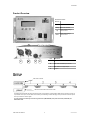
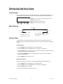
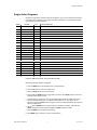
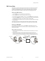
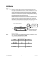
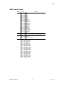
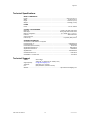
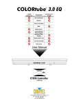
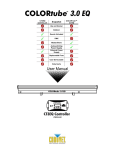
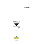
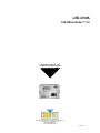
LED-CHVA COLORcontroller™ 2.0 USER MANUAL CHAUVET, 3000 N 29th Ct, Hollywood, FL 33020 U.S.A (800) 762-1084 – (954) 929-1115 FAX (954) 929-5560 www.chauvetlighting.com 2005-10-10/16:02 Table of Content BEFORE YOU BEGIN....................................................................................................................................................... 3 WHAT IS INCLUDED .......................................................................................................................................................................................................... 3 UNPACKING INSTRUCTIONS .............................................................................................................................................................................................. 3 AC POWER ..................................................................................................................................................................................................................... 3 SAFETY INSTRUCTIONS .................................................................................................................................................................................................... 3 INTRODUCTION ............................................................................................................................................................... 4 FEATURES ....................................................................................................................................................................................................................... 4 DMX CHANNEL SUMMARY ............................................................................................................................................................................................... 4 PRODUCT OVERVIEW....................................................................................................................................................................................................... 5 SETUP .............................................................................................................................................................................. 5 OPERATING INSTRUCTIONS .......................................................................................................................................... 6 CONTROL PANEL ............................................................................................................................................................................................................. 6 MENU DIAGRAM............................................................................................................................................................................................................... 6 SYSTEM SETUP ............................................................................................................................................................................................................... 6 Initial Setup......................................................................................................................................................................................................... 6 Re-initialization ................................................................................................................................................................................................... 6 SINGLE ACTION PROGRAMS ............................................................................................................................................................................................. 7 Choosing Single Action Programs ..................................................................................................................................................................... 7 DMX CONTROL MODE ..................................................................................................................................................................................................... 8 Setting the DMX address ................................................................................................................................................................................... 8 Running in DMX Mode ....................................................................................................................................................................................... 8 Daisy Chain Connection..................................................................................................................................................................................... 8 APPENDIX ........................................................................................................................................................................ 9 DMX PRIMER .................................................................................................................................................................................................................. 9 Fixture Linking .................................................................................................................................................................................................... 9 DMX CHANNEL VALUES ................................................................................................................................................................................................ 10 RETURNS PROCEDURE .................................................................................................................................................................................................. 11 CLAIMS ......................................................................................................................................................................................................................... 11 TECHNICAL SPECIFICATIONS .......................................................................................................................................................................................... 12 TECHNICAL SUPPORT .................................................................................................................................................................................................... 12 LED-CHVA User Manual 2 2005-10-10/16:02 BEFORE YOU BEGIN What is included COLORcontroller™ 2.0 Notice! The LED COLOR - - - -™ 2.0 System Series is not compatible with the previous non 2.0 system. 1 x LED-CHVA COLORcontroller™ 2.0 1 x LED-SIG15A Signal Extension Cable 1 x AC-DC Power Adapter Manual and Warranty Card Unpacking Instructions Immediately upon receiving a product, carefully unpack the carton, check the contents to ensure that all parts are present, and have been received in good condition. Notify the shipper immediately and retain packing material for inspection if any parts appear damaged from shipping or the carton itself shows signs of mishandling. Save the carton and all packing materials. In the event that a fixture must be returned to the factory, it is important that the fixture be returned in the original factory box and packing. AC Power To determine the power requirements for a particular product, see the label affixed to the back plate of the product or refer to the product’s specifications chart. A product’s listed current rating is its average current draw under normal conditions. All fixtures must be powered directly off a switched circuit and cannot be run off a rheostat (variable resistor) or dimmer circuit, even if the rheostat or AC Voltage Switch Example dimmer channel is used solely for a 0% to 100% switch. Before applying power, check that the source voltage matches the product’s requirement. Check the product or device carefully to make sure that if a voltage selection switch exists that it is set to the correct line voltage you will use. Warning! If applicable, verify that the power select switch on your unit matches the line voltage applied. All fixtures must be connected to circuits with a suitable Earth Ground. Safety Instructions Please read these instructions carefully, which includes important information about the installation, usage and maintenance? Please keep this User Guide for future consultation. If you sell the unit to another user, be sure that they also receive this instruction booklet. Always make sure that you are connecting to the proper voltage and that the line voltage you are connecting to is not higher than that stated on decal or rear panel of the fixture. This product is intended for indoor use only! To prevent risk of fire or shock, do not expose fixture to rain or moisture. Make sure there are no flammable materials close to the unit while operating. The unit must be installed in a location with adequate ventilation, at least 50cm from adjacent surfaces. Be sure that no ventilation slots are blocked. Always disconnect from power source before servicing or replacing lamp or fuse and be sure to replace with same lamp source. Caution! Secure fixture to fastening device using a safety chain. Never carry the fixture solely by its head. Use its carrying handles. Maximum ambient temperature is Ta: 40°. Do not operate fixture at temperatures higher than this. In the event of serious operating problem, stop using the unit immediately. Never try to repair the unit by yourself. Repairs carried out by unskilled people can lead to damage or malfunction. Please contact the nearest authorized technical assistance center. Always use the same type spare parts. Don’t connect the device to a dimmer pack. Make sure power cord is never crimped or damaged. Never disconnect power cord by pulling or tugging on the cord. Avoid direct eye exposure to lamp while it is on. There are no user serviceable parts inside the unit. Do not open the housing or attempt any repairs yourself. In the unlikely event your unit may require service, please contact CHAUVET. LED-CHVA User Manual 3 2005-10-10/16:02 INTRODUCTION Features COLORcontroller™ 2.0 Control Features 4 channel DMX controlled device 7 independently selectable preset colors, 13 programmed chases adjustable in speed or flash rate, Auto mode and Sound Active Speed control channel Flash rate control channel (1-20 Fps) Selection of preset color combinations Features 1000 tubes 30 varied patterns (with color changes) Built in Microphone Digial LCD display DMX Channel Summary CHANNEL FUNCTION 1 Color, Programs, Auto 2 Speed 3 Flash 4 Color Combinations LED-CHVA User Manual 4 2005-10-10/16:02 Introduction Product Overview SEGMENT BUTTONS BUTTONS Mode Returns to Main Menu Setup Enter menu selection Up Down ITEM A B C D Steps backward through menu functions Steps forward through menu functions DESCRIPTION A 3-Pin female XLR DMX output connector B 3-Pin male XLR DMX input connector C COLORtube™ 2.0 signal output D DC input SETUP LED-CHVA Controller LED-PC5A Power cable connects to AC outlet The diagram above illustrates the tubes connected in series or as required for normal operation. Both plugs are unique in that one is a 2-pin and the other a 4-pin. Connect each tube in series by each matching connector and plug. The 2-pin connector is used for power. The 4-pin connector is used for signal. For every 30 tubes connected you will need a signal booster (LED-BOOSTA) and a power connection (LED-PC5A) to a different AC outlet. LED-CHVA User Manual 5 2005-10-10/16:02 OPERATING INSTRUCTIONS Control Panel On the control panel you can set the controller for single action mode where preset programs are run either statically, automatically or by sound-activation or assign a starting DMX channel address. [MODE] Returns to Main menu or step backward through functions [SET UP] Enters menu selection [UP] Steps backward through menu selection [DOWN] Steps forward through menu selection MODE SETUP UP DOWN Menu Diagram Main Menu M System Setup 1 DMX Ch M Single Action (0 – 508) For a detailed listing of Single Action programs proceed to the next page. 2 Set Address (N / A) 3 Tube Amount (0 – 999) System Setup You will need to let the controller be aware of the number of tubes connected in series. This is essential in order for the chase and flow programs to perform correctly through out the entire stretch of tubes. In it ia l S et u p 1. Press the MODE button until the display shows “M System Setup”. 2. Press the SETUP button then the UP button once. It will show “3 Tube Amount”. 3. Press the SETUP button to enter the function. A number will now appear to the right of the text as shown here in an example. “3 Tube Amount 34”. 4. Use the UP and DOWN buttons to locate a number between 0 and 999. This represents the number of tubes connected. 5. Press the MODE button to set this function. Re- in it i al iz a t io n Whenever a tube is removed, replaced or exchanged please follow the following instructions. 1. Press the MODE button until the display shows “M System Setup”. 2. Press the SETUP button then the UP button twice. It will show “2 Set Address”. 3. Press the SETUP button to re-initialize. 4. Proceed to prior instruction “Initial Setup” and re-do. LED-CHVA User Manual 6 2005-10-10/16:02 Operating Instructions Single Action Programs Single Action programs are pre-built chase and flow patterns. They can be executed either manually or by DMX control. Depending on the program the following attributes can be modified; Run Speed, Flash Frequency and Color Selection. NUMBER 1 2 PROGRAM Black Red TYPE Static Static None None 3 Green 5 Yellow Static None 7 Cyan Static None 4 6 8 9 10 11 Blue Purple White Color Change Slow Flow 1 Slow Flow 2 Static MODIFICATIONS (MODIFIER) Static Static Static None None None None Auto Run Speed, Flash Speed Auto Run Speed, Flash Speed Auto 12 Roll Chase 1 14 Multi Color Auto Run Speed, Flash Speed Fast Flow 2 Auto Run Speed, Flash Speed 13 15 16 17 18 Roll Chase 2 Fast Flow 1 Fast Flow 3 Fast Flow 4 19 2 Color Chase 21 Color Fade 20 22 2 Color Flow Auto Run Auto Run Speed, Flash Speed Auto Auto Auto Auto Auto Auto Auto Auto Run Speed, Flash Speed Run Speed, Flash Speed Run Speed, Flash Speed Run Speed, Select Color Combination (1) Run Speed, Select Color Combination (1) Run Speed, Flash Speed, Select Color Combination (1) Run Speed, Flash Speed, Select Color Combination (1) Run Speed Run Speed, (runs all built in programs) (1) Refer to “DMX Channel Values” for Color Combinations Table. C h o o s i n g S i n g l e Ac t i o n P r o g r a m s 1. Press the MODE button until the display shows “M System Setup”. 2. Press the UP button to arrive at “M Single Action”. 3. Press the SETUP button to enter menu function. 4. Press the UP and DOWN buttons to toggle built in programs. Press SETUP button to choose the presently viewed program number. 5. Upon selecting the program, the menu will immediately display whatever modifier may exist for that individual program selected. It can display “Flash Speed: 100” or “Run Speed: 100” for example. Pressing the SETUP button will toggle the various modifiers available for the program as listed in the table above. 6. Use the UP and DOWN buttons to adjust the values of modifiers accordingly. Remember that SETUP will toggle the various options while UP and DOWN changes the values. 7. Press the MENU button to retain the new settings.. 8. Press MENU again if necessary to return to the Main Menu. LED-CHVA User Manual 7 2005-10-10/16:02 Operating Instructions DMX Control Mode With exception to the system setup process all control functions on the controller can be accessed and executed externally via a Universal DMX controller. First you must connect the LED-CHVA controller to an existing DMX daisy chain. The controller is addressable just like any other DMX device or fixture and it will be controlled as if it were a fixture in most intelligent light consoles. S et t i n g t h e DM X ad dr es s 1. Press the MODE button until the display shows “M System Setup”. 2. Press the SETUP button to enter the “M System Setup” menu function. 3. The controller should display immediately “1 Dmx Ch”. Press the SETUP button to select function. 4. Use the UP and DOWN buttons to increase or decrease the channel values. This value represents the starting address for this device. The controller occupies 4 channels of DMX 5. The unit will now respond to DMX command. Do not press any other buttons other than to change the channel values. The next step may require you to create a device profile within your lighting controller. Proceed to section “DMX Channel Values” for a detailed chart of the control values for each channel of DMX. Ru n n in g in DM X M ode If the control panel menu displays “1 Dmx Ch“ press SETUP to activate DMX control mode. For instructions on arriving at this menu item repeat the instructions “Setting the DMX address” located directly above this subject. Da is y Ch ai n Co nn e ct i on 1. Connect the (male) 3 pin connector side of the DMX cable to the output (female) 3 pin connector of the first fixture. 2. Connect the end of the cable coming from the first fixture which will have a (female) 3 pin connector to the input connector of the next fixture consisting of a (male) 3 pin connector. Then, proceed to connect from the output as stated above to the input of the following fixture and so on. From Controller DMX Daisy Chain COLORtube™ 2.0 COLORcontroller™ 2.0 LED-CHVA User Manual 8 2005-10-10/16:02 APPENDIX DMX Primer There are 512 channels in a DMX-512 connection. Channels may be assigned in any manner. A fixture capable of receiving DMX-512 will require one or a number of sequential channels. The user must assign a starting address on the fixture that indicates the first channel reserved in the controller. There are many different types of DMX controllable fixtures and they all may vary in the total number of channels required. Choosing a start address should be planned in advance. Channels should never overlap. If they do, this will result in erratic operation of the fixtures whose starting address is set incorrectly. You can however, control multiple fixtures of the same type using the same starting address as long as the intended result is that of unison movement or operation. In other words, the fixtures will be slaved together and all respond exactly the same. DMX fixtures are designed to receive data through a serial Daisy Chain. A Daisy Chain connection is where the DATA OUT of one fixture connects to the DATA IN of the next fixture. The order in which the fixtures are connected is not important and has no effect on how a controller communicates to each fixture. Use an order that provides for the easiest and most direct cabling. Connect fixtures using shielded two conductor twisted pair cable with three pin XLR male to female connectors. The shield connection is pin 1, while pin 2 is Data Negative (S-) and pin 3 is Data positive (S+). CHAUVET carries 3-pin XLR DMX compliant cables, DMX-10 (33’), DMX-4.5 (15’) and DMX-1.5 (5’) Figure 1 - DMX connector configuration 1 3 2 COMMON INPUT 1 3 1 3 DMX + 2 2 DMX - Resistance 120 ohm 1/4w between pin 2 (DMX -) and pin 3 (DMX +) of the last fixture. OUTPUT Termination reduces signal errors and to avoid signal transmission problems and interference, it is always advisable to connect a DMX signal terminator. F ix t u re L i n k in g Note! If you use a controller with a 5 pin DMX output connector, you will need to use a 5 pin to 3 pin adapter. CHAUVET Model No: DMX5M. The chart below details a proper cable conversion: 3 PIN TO 5 PIN CONVERSION CHART LED-CHVA User Manual Conductor 3 Pin Female (output) 5 Pin Male (Input) Ground/Shield Pin 1 Pin 1 Data ( - )signal Pin 2 Pin 2 Data ( + ) signal Pin 3 Pin 3 Do not use Do not use Do not use Do not use 9 2005-10-10/16:02 Appendix DMX Channel Values DEFAULT LED-CHVA User Manual VALUE FUNCTION 1 000 011 012 023 024 035 036 047 048 059 060 071 072 083 084 095 096 114 115 119 120 131 132 143 144 155 156 167 168 179 180 191 192 203 204 215 216 227 228 239 240 251 252 255 Programs Black Red Green Blue Yellow Purple Light Blue White Color Change Slow Flow 1 Slow Flow 2 Roll Chase 1 Roll Chase 2 Multi Color Fast Flow 1 Fast Flow 2 Fast Flow 3 Fast Flow 4 2 Color Chase 2 Color Flow Color Fade Auto Run 2 000 255 Run Speed Slow > Fast, (1 step/Minute) > (100 steps/Second) 3 000 002 003 255 Flash Speed Always On Slow > Fast (1 – 20Hz) 4 000 011 012 023 024 035 036 047 048 059 060 071 072 083 084 095 096 107 108 119 120 131 132 143 144 155 156 167 168 179 180 191 192 203 204 215 216 227 228 239 240 255 Color Combinations Red & Green Red & Yellow Red & Blue Red & Purple Red & Cyan Red & White Green & Yellow Green & Blue Green & Purple Green & Cyan Green & White Yellow & Blue Yellow & Purple Yellow & Cyan Yellow & White Blue & Purple Blue & Cyan Blue & White Purple & Cyan Purple & White Cyan & White 10 2005-10-10/16:02 Returns Procedure Returned merchandise must be sent prepaid and in the original packing, call tags will not be issued. Package must be clearly labeled with a Return Merchandise Authorization Number (RA #). Products returned without an RA # will be refused. Call CHAUVET and request RA # prior to shipping the fixture. Be prepared to provide the model number, serial number and a brief description of the cause for the return. Be sure to properly pack fixture, any shipping damage resulting from inadequate packaging is the customer’s responsibility. CHAUVET reserves the right to use its own discretion to repair or replace product(s). As a suggestion, proper UPS packing or double-boxing is always a safe method to use. Claims Damage incurred in shipping is the responsibility of the shipper; therefore the damage must be reported to the carrier upon receipt of merchandise. It is the customer's responsibility to notify and submit claims with the shipper in the event that a fixture is damaged due to shipping. Any other claim for items such as missing component/part, damage not related to shipping, and concealed damage, must be made within seven (7) days of receiving merchandise. LED-CHVA User Manual 11 2005-10-10/16:02 Appendix Technical Specifications WEIGHT & DIMENSIONS Length..................................................................................................................... 205.74 mm (8.1 in) Width.......................................................................................................................... 101.60 mm (4 in) Height ....................................................................................................................... 30.48 mm (1.2 in) Weight....................................................................................................................... 0.68 Kgs (1.5 lbs) POWER Power.......................................................................................................................... 12V DC, 500mA CONTROL & PROGRAMMING Data input ............................................................................................. locking 3-pin XLR male socket Data output ........................................................................................ locking 3-pin XLR female socket Data pin configuration ............................................................................pin 1 shield, pin 2 (-), pin 3 (+) Protocols.....................................................................................................................DMX-512 USITT Control Channels ................................................................................................................................4 Protocols (2)................................................................................................... Proprietary data protocol ORDERING INFORMATION Accessories for COLORtube™ 2.0 System Power Extension 15’ ..................................................................................................... LED-EXTP15A Power Extension 5’ ......................................................................................................... LED-EXTP5A Power Cable (Direct to Outlet)............................................................................................. LED-PC5A Signal Cable Extension 15’............................................................................................... LED-SIG15A Signal Cable Extension 5’ .................................................................................................. LED-SIG5A Signal Booster................................................................................................................LED-BOOSTA COLORcontroller™ 2.0 .......................................................................................................LED-CHVA COLORtube™ 2.0 LED Tube ............................................................................................... LED-T40A Technical Support Address: Service Dept. 3000 N 29th Ct, Hollywood, FL 33020 (U.S.A.) Support (Email): [email protected] Telephone: (954) 929-1115 - (Press 4) Fax: (954) 929-5560 - (Attention: Service) Website:............................................................................................... http://www.chauvetlighting.com LED-CHVA User Manual 12 2005-10-10/16:02