1
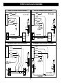
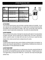
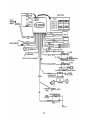
CS-2200WST
WIRELESS SIREN / HOOD / TRUNK SYSTEM
INSTALLATION & OPERATING INSTRUCTIONS
INTRODUCTION
CONGRATULATIONS on your choice of an OnGuardTM Vehicle Security System by CrimeStopper Security
Products Inc. This booklet contains the information necessary for installing, using, and maintaining your alarm
system. If any questions arise, contact your installation dealer or CrimeStopper Security Products Inc. at the
Tech Support number below.
*IMPORTANT INFORMATION: Primary and Optional Features:
-PRIMARY: These are features that must be connected in order for the system to operate properly; i.e. the
Siren, L.E.D., +12V Power, Ground, Door pin, Flashing lights Override/Program/Valet Button etc.
-OPTIONAL: These are features to be connected if desired or agreed upon by the installing dealer. These
features may also require additional parts and/or labor fees. Consult with your installer beforehand; i.e. Door
Locks, Starter disable, Hood/Trunk trigger, and Auxiliary Remote Outputs etc.
This installation book is designed for the installer or individual with an existing understanding of automotive
electrical systems, along with the ability to test and connect wires for proper operation. To ease installation,
we suggest that you READ THIS MANUAL before beginning your installation. This book is provided as a
GENERAL GUIDLINE and the information contained herein may differ from your vehicle.
TECH SUPPORT
Mon-Fri 8:00 AM-4:30 PM Pacific Time
(800) 998-6880
REV. B 4. 2006
This device complies with FCC Rules part 15. Operation is subject to
the following two conditions: 1) This device may not cause interference,
and (2) this device must accept any interference that may be received,
including interference that may cause undesired operation. The
manufacturer is not responsible for any radio or TV interference caused
by unauthorized modification to this equipment. Such modification
could void the user's authority to operate the equipment.
TABLE OF CONTENTS
Installation Cautions & Warnings…….……………………………….……………………………………………2
Control Module & Component Mounting……………...……………………..……………………….…………..3
Wiring……..……………………………………………………………………………………..……………….…….3-4
Power Door Lock Wiring……………………………………………………….………………………….…..……5-6
Power Door Lock Diagrams…………………………………………………………………………………………7
Operating Instructions………………………..…………………………………….……………………..……….8-10
Car Jack Protection Features…………..……………………………………………...…………………….……..11
Programming, Transmitter Programming…….………………………………………………………………11-12
System Wiring Diagram………………………………………………………………....……………..……………13
INSTALLATION CAUTIONS & WARNINGS
BEFORE BEGINNING, check all vehicle manufacturer cautions and warnings regarding electrical service (AIR
BAGS, ABS BRAKES, ENGINE COMPUTERS, BATTERY etc.).
WE RECOMMEND the use of a VOLT/OHM METER to test and verify wiring circuits. Test lights or illuminated
probes can cause damage to on-board computer or engine management systems.
DO NOT exceed maximum output ratings or damage may occur. Electrical current limits for this alarm are
listed where applicable on the system diagram (Page 13). If you are unsure about the current load, of a
specific circuit on your vehicle, measure the load first with an amp-meter before connecting.
WE RECOMMEND that the MAIN SYSTEM FUSE be REMOVED before jump starting, using a battery
charger, or changing the battery. A voltage surge or high boost condition could damage alarm circuits.
DO NOT ROUTE ANY WIRING THAT MAY BECOME ENTANGLED with brake, and gas pedals, steering
column, or any other moving parts in the vehicle.
2
CONTROL MODULE & COMPONENT MOUNTING
DO NOT Mount the control unit in the engine compartment or where the control unit or wiring harness
where they can become entangled with moving parts such as brake/gas/clutch pedals, or the steering
column! The alarm control module should be mounted in a concealed location. The Placement of the
module will affect the distance from which the remote transmitter can control the unit. The antenna wire
should be routed away from any metal if possible. Do not alter the length of the antenna wire or route it with
other wires. Do not ground the antenna wire. Fasten the module to a bracket or wire harness using the cable
ties provided. Under dash Mounting: If you are locating the control unit underdash, mount it as high as
possible, not easily located by an intruder. Driver’s Side Under dash mounting provides an easy location for
wiring most of the system’s connections, however this is a common location for an intruder to check for an
alarm after breaking into the vehicle.
WIRELESS SIREN / HOOD: Mount the siren under the hood to an inner fender-well, wheel-well, or other body
surface with the open end facing downward. Run the red siren wire to constant +12V. Ground the black to
the body metal near the siren or you can use one of the siren’s mounting screws for a ground. The white wire
connects to “-“ hook pin switch.
LED: Mount the red LED in a visible location on the dashboard or console.
WIRELESS TRUNK: Mount inside the trunk close to the trunk light connector, so that it is easy to find the wire
for installation. NOTE: Do not mount the wireless trunk piece on any metal surface. It can be tied to any
harness to hold it. (SEE PAGE 13 FOR INSTALLATION)
Shock Sensor: Mount the included shock sensor with wire ties to an under dash wire harness or fasten with
screws to firewall or side paneling. Use the adjustment screw to set the sensitivity of the sensor. One screw
adjusts both
Valet/Programming Button: Mount the Valet/Override/Program push-button in a hidden but accessible
location. It is REQUIRED for emergency disarm, programming features and entering valet mode.
WIRING
GRAY WIRE: (-) AUX REMOTE OUTPUT 1 (Optional, may require a relay) (300mA)
Connect to the Negative trunk release circuit or to the activation circuit of an auxiliary module or device. If the
circuit requires +12V, then a relay is required. RELAY WIRING: Connect the purple wire to terminal 85,
connect relay terminals 86 and 87 to +12V constant power. Connect terminal 30 of the relay to the +12V
positive device/circuit to be activated.
3
WIRING
BLACK/WHITE WIRE: (-) DOME LIGHT ILLUMINATION OUTPUT (Optional, requires a relay)
Connect Black/White wire to terminal 85 of the relay (relay not included). Connect terminal 86 of the relay to
+12 Volt constant power. For POSITIVE dome light circuits, connect terminal 87 to fused +12V constant. For
NEGATIVE dome light circuits, connect terminal 87 to chassis ground. Connect terminal 30 of the relay to the
dome light activation circuit in the vehicle.
ORANGE WIRE: (-) NEGATIVE ARMED OUTPUT / STARTER DISABLE (300mA ground, optional)
This wire becomes a (-) ground output when system is armed. This output is used for disabling the starter or
to activate optional devices such as extra sensors, LED’s, window roll-up modules, voice modules etc. For
starter kill, cut starter wire and connect between 87A and 30 on relay. Connect orange wire to 85 and connect
86 to an ignition source that has voltage in the ON and CRANKING position. (See wiring diagram for relay
configuration Pg. 13).
GREEN WIRE: (-) DOOR TRIGGER
Identify the wire that reads ground when any door is open and 12 volts when all doors are closed. Some
vehicles may have isolated door triggers. In this case you may need to run additional wires from other doors
or go directly to the wire that triggers the vehicle’s interior dome light. One vehicle will not require the use of
BOTH door trigger wires.
YELLOW WIRE: IGNITION SWITCHED “ON” AND “START” +12 VOLTS
Connect to an IGNITION wire (or fuse in the fuse box) that shows +12 Volts when the key in both “On” and
“Start” (WHEN CRANKING) positions.
BLACK WIRE: SYSTEM CHASSIS GROUND
The black wire MUST be connected to the CHASSIS METAL of the vehicle. Scrape away any paint or debris
from the connection point and use a star washer to ensure a good connection. Keep the ground wire short.
WHITE WIRE: +12V FLASHING PARKING LIGHT OUTPUT RIGHT & LEFT (10A)
Connect to the switched parking light wire at the back of the light switch. If this is not possible, connect
directly to on of the parking lights at the front of the vehicle. European vehicles require separate right and left
circuits. Use of a dual relay or 2 diodes to separate the output signal.
4
3
WIRING
RED WIRE: +12V POWER INPUT (15 AMP FUSE)
Connect to +12Volt source with supplied fuse & holder. Recommended location for this connection is at the
vehicle battery positive terminal.
2 PIN PLUG (BLUE): PROGRAM/OVERRIDE PUSHBUTTON
2 PIN PLUG (RED): LED INDICATOR (RED FLASHING LIGHT)
SHOCK SENSOR: The sensor supplied with this
system does not require any additional wiring.
Simply mount the sensor in a suitable location, plug
it in, and adjust sensitivity.
3 PIN SENSOR PLUG: White wire: Negative trigger, Black wire: sensor ground, Red wire: sensor +12V
power
POWER DOOR LOCK WIRING
6 PIN DOOR LOCK PLUG 18 GA. (Optional/Onboard Relays):
Gray
White
Violet
Blue
Green
Violet/white
Door Lock Relay Term. #87A:
Door Lock Relay Term. #30:
Door Lock Relay Term. #87:
Door Unlock Relay Term. #87A:
Door Unlock Relay Term. #30:
Door Unlock Relay Term. #87:
Normally Closed
Common [Lock Output]
Normally Open [Polarity Input for Lock
Normally Closed
Common [Unlock Output]
Normally Open [Polarity Input for Unlock Relay]
Relay]
DETERMINING DOOR LOCK TYPE: We recommend determining the type of locking system the vehicle has
before connecting any wires. Incorrect connection may result in damage to the alarm and/or vehicle locking
system. This door lock information is provided as a guide. Your vehicle may differ.
NEGATIVE TRIGGER (-): Many Imports; late model Fords & General Motors
Negative trigger door lock systems send a negative (ground) pulse to existing factory relays to lock and unlock
the vehicle doors.
POSITIVE TRIGGER (+): Many General Motors; Chrysler / Dodge / Plymouth
Positive trigger door lock systems send a positive (+12V) pulse through factory relays to lock and unlock
doors.
5
POWER DOOR LOCK WIRING
REVERSE POLARITY: Many Ford / Lincoln / Mercury / Dodge / Chrysler / Plymouth and early 90s GM
Trucks
Reverse polarity systems use no relays, but instead the door lock/unlock motors are controlled directly from
the lock and unlock switches in the door. The lock and unlock wires rest at Negative Ground when not in use.
When the lock or unlock button is pressed, one of the circuits is “lifted” and replaced with +12V causing a lock
or unlock.
SINGLE WIRE (DUAL VOLTAGE): Late model Chrysler / Dodge / Plymouth vehicles, some 2000-up GM
Dual voltage systems have lock/unlock switches that send varying amounts of positive voltage or negative
ground current to the same wire for both lock and unlock. When the vehicle’s Body Computer Module (BCM)
or door lock module senses different voltages on this wire, the system will either lock or unlock. Single wire
door lock systems use resistors.
DATABUS SYSTEMS (2003 GM TRUCKS & SUVs, ’99-04 Jeep Grand Cherokee
Databus systems send low current “data messages” to the door lock controllers in order to lock and unlock the
vehicle. To install aftermarket systems in these vehicles, an interface module is required that converts the
regular lock/unlock pulses into “data messages” to allow locking & unlocking. Interface modules are sold
separately.
6
POWER DOOR LOCK DIAGRAMS
POSITIVE TRIGGER DOORLOCK WIRING
NEGATIVE TRIGGER DOORLOCK WIRING
X
GRAY
X=
WHITE
X=
NOT USED
WHITE
VIOLET
VIOLET
X
BLUE
X
GRAY
NOT USED
X
BLUE
GREEN
GREEN
VIOLET/WHITE
VIOLET/WHITE
+12V +
FUSED
L
FACTORY
LOCK WIRE
L
LOCK WIRE
LOCKING
LOCKING
UL
UNLOCK WIRE
UL
RELAYS
UNLOCK WIRE
RELAYS
AFTERMARKET MOTOR DOOR LOCK WIRING
REVERSE POLARITY DOOR LOCK WIRING
GRAY
GRAY
WHITE
WHITE
VIOLET
VIOLET
BLUE
BLUE
GREEN
GREEN
VIOLET/WHITE
VIOLET/WHITE
+12V +
FUSED
+12V
FUSED
+
FACTORY
UL
L
UL
CUT
CUT
+
UNLOCK WIRE
L
LOCK WIRE
7
OPERATING INSTRUCTIONS
ALARM OPERATION CONDITION QUICK CHART:
SIREN
CHIRPS
1 Siren Chirp
2 Siren Chirp
3 Siren Chirp
PARKING LIGHT FLASH
SYSTEM STATUS
1 Parking Light Flash
2 Parking Light Flash
3 Parking Light Flash
System Arm
System Disarm
System arm w/door open
or Dome light delay on
System disarm, When it
has been triggered.
Pre warning or car locator
4 Siren Chirp 4 Parking Light Flash
5 Siren Chirp 5 Parking Light Flash
AUX. #1
(TRUNK
POP)
LOCK/
UNLOCK
ACTIVE ARMING
To arm the alarm and lock the doors, press the #1 Button (Lock/Unlock Symbol) on the transmitter. You will
hear a single siren chirp and the lights will flash once. The system will arm, the doors will lock and the starter
will be disabled if these optional features are installed. After a short 10 second delay to allow vehicle and
electronics to settle, the system will be completely armed. The red LED in the vehicle will slow flash.
ALARM TRIGGERING
If there is an intrusion into the vehicle or hard impact to the body will sound the alarm for 30 seconds and flash
the lights for 60 seconds. After 60 seconds the siren and lights will stop, but the alarm is still armed to
continue to protect the vehicle. If an intruder left the door open, the unit will cycle a second time before
stopping and then continue to protect the other un-tampered zones of the vehicle.
DISARMING
To disarm the alarm and unlock the doors, press the #1 Button (Lock/Unlock Symbol) on the transmitter. You
will hear 2 siren chirps and the lights will flash twice. LED stops flashing or fast flashing. Doors will unlock and
dome light will turn on if these optional features are installed.
ALARM TRIGGER RESET
If the armed alarm system is triggered while you are within the range of the remote, pressing the #1 Button will
only shut off the siren and lights while leaving the alarm still in an armed status. To disarm the alarm when it
is in a triggered status, you must press the #1 Button twice. You will hear 4 siren chirps and the parking lights
will flash 4 times.
8
OPERATING INSTRUCTIONS
REMOTE PANIC PROTECTION
To sound the alarm upon command (panic), press and hold Button #1 for at least 4 seconds until the siren
sounds. Press Button #1 again to reset panic mode.
TRUNK/HATCH POP (REMOTE AUX. OUTPUT 1, OPTIONAL) (300mA)
To pop the trunk (if optional feature is installed), press Button #2 twice within 2 seconds on the transmitter. If
the system is armed, unit will trip the alarm system when opening the trunk. If the system is disarmed, press
Button #2 twice within 2 seconds, the parking lights will flash 5 times and the trunk will open.
PRE-WARNING SHOCK PROTECTION & SENSOR ADJUSTMENT
If a low-level shock to the vehicle is detected, pre-warning protection will activate sounding 5 siren chirps and
5 light flashes. If a hard impact is detected the shock sensor should trip the alarm system. Once it is
mounted, adjust the sensor as needed by turning the adjustment screw clockwise to increase or counterclockwise to decrease the sensitivity.
SILENT ARM/DISARM THROUGH REMOTE (BUTTON #2)
This system can be armed and disarmed without siren chirps on an “as needed” basis. Press and release
Button #2 then Button #1 to Arm and Disarm system without chirps.
EMERGENCY OVERRIDE & DISARM
If you have lost the transmitter or it stops working for any reason and the Alarm is armed, you will have to
perform and emergency override & disarm to shut the alarm off. Open the door with the key, (alarm will
sound). Turn the ignition on and press the override/program button 4-5 seconds (until siren stops). The Alarm
will disarm.
VALET MODE
To disable the Alarm system for vehicle service or otherwise, turn the ignition on and press the
override/program button 4-5 seconds until the dash LED turns on solid and you see 1 parking light flash.
Repeat the process to exit VALET mode, you will see 2 parking light flashes, and the LED will turn off.
Lock/Unlock and AUX features will still operate in when in VALET mode.
PRIOR INTRUSION ALERT
If the system was tripped in your absence, the dash LED will be slowly flash. When the system is disarmed
you will hear 4 chirps, and see 4 parking light flashes. Carefully inspect your vehicle.
9
OPERATING INSTRUCTIONS
OPEN ZONE ALERT & BYPASS
If the system detects a faulty or open zone (Door left open) when the system is ACTIVELY ARMED, the siren
will chirp 3 times along with 3 light flashes. The faulty zone will be automatically bypassed.
CAR LOCATING
When the system is armed, press and hold Button #2 for 3 seconds, 5 siren chirps, and 5 parking light flashes.
IGNITION-CONTROLLED DOORLOCKS (See page 13 for jumper setting)
If this feature is enabled, the doors will automatically lock when the ignition is turned on and will unlock when
the ignition is turned off. The jumper setting default = ON.
PASSIVE ARMING / PASSIVE LOCK MODES (See page 13 for jumper setting)
Passive (Automatic) Arming will occur 30 Seconds after the ignition is turned off and the last door has been
closed. The LED will begin flashing rapidly while counting down. If a door is reopened, the system will wait
(LED solid) for the door or zone to close before arming. The unit will chirp once and flash the lights once.
Doors will lock if the “Passive Locking” jumper setting = ON. Passive Arm/Lock may qualify for insurance
discounts-check with your agent or proprietor. The default setting = ON.
DOME LIGHT ILLUMINATION (OPTIONAL)
This feature turns on the vehicles dome light upon disarm for 30 seconds or until the key is inserted and
turned on. This will provide illuminated entry to your vehicle at night or in dimly lit areas for safety and security.
DOOR LOCK/UNLOCK PULSE TIME (See page 13 for jumper setting)
This feature controls the amount of time 0.5 seconds (jumper off) or 4 seconds (jumper on) for the lock/unlock
pulse. This setting may be required for 1980/1990 European vehicles that require a long pulse for vacuum
door lock systems.
ACTIVE RE-ARMING (FAIL-SAFE PROTECTION)
The Active Re-arming feature allows the system will re-arm itself 30 seconds after being disarmed with the
transmitter if a door has not yet been opened. This is handy if the vehicle is accidentally disarmed (via the
transmitter in your pocket) without you knowing it. This feature can also be turned ON. Active re-arm default
is OFF, see page 11 for more details.
10
CARJACK PROTECTION
ANTI HIJACK
When the Ignition is on (running), press button #1 for 3 seconds. Parking lights will flash TWICE to confirm
the Carjack countdown sequence. 40 Seconds later, the unit will begin a Carjack Cycle consisting of 20
seconds of warning chirps turning into a full system activation with siren/flashing light pulses for up to 5 min.
To reset press button #1 again or turn ignition on. then press and hold override for 5 seconds to disarm unit
and exit anti-hijacking.
TRANSMITTER PROGRAMMING
Note: 2 remotes cannot be programmed at the same time. Repeat these procedures for the second remote.
1.
2.
3.
4.
5.
The system must be in the disarmed state.
Ignition key must be in the ON position.
Press the valet button 3 times and hold it ON at the 3rd time.
After 3 seconds, the parking light will flash twice to indicate the transmitter is in code-learning mode.
Press any of the transmitter buttons once.
6. The parking lights will flash 4 times to confirm that the code has been learned. (Unit codes up to 5 remotes)
PROGRAMMING
SHOCK SENSOR
Press button #2 within 3 seconds after the system is in armed state. You can now enable or disable shock
sensor as shown in the table below:
Press # of Times
1st
2nd
3rd
Function
Disable shock prewarning sensing
Disable shock sensor sensing
Enable shock sensor sensing
Indication
1 Siren chirp / 1 light flash
2 Siren chirps / 2 light flashes
3 Siren chirps / 3 light flashes
Note
If mute has been selected in
the armed state, only the
lights will flash!
1. The system will automatically detect shock sensor when the system is in the armed state.
2. Press button #2 four times, this will be the same as pressing once. Press button #2 five times, this will
be the same as pressing twice. Press button #2 six times, this will be the same as pressing 3 times,
etc…
11
PROGRAMMING
ACTIVE RE-ARM WITH LOCK (ENABLE/DISABLE)
1. The system must in the disarmed state.
2. Ignition key must be in the ON position.
3. Press the valet button 4 times and hold it ON at the 4th time.
4. After 3 seconds, the parking light will flash 3 times indicating that it is disabled (default) and 4 times
indicating that it is enabled.
DOOR TRIGGER DELAY (30/60 SECOND)
1. The system must be in the disarmed state.
2. Turn the ignition to the ON position.
3. Press the valet button 5 times and hold it ON at the 5th time.
4. After 3 seconds, the parking light will flash 4 times indicating a 60 second door trigger delay and 3 times
for a 30 second door trigger delay (default).
PROGRAM MAIN MODULE TO WIRELESS SIREN
1. Disconnect power (black and red wire of the wireless siren) for at least 10 seconds.
2. Connect power (black and red wire of the wireless siren).
3. Press button #1 no later than 5 seconds after power has been re-connected.
PROGRAM WIRELESS HOOD OR WIRELESS TRUNK TO MAIN MODULE
1. The system must be in the disarmed state.
2. Turn the ignition to the ON position.
3. Press the valet button 3 times and hold it ON at the 3rd time.
4. After 3 seconds, the parking light will flash twice to indicate transmitter code learning mode.
a. For wireless hood, you must have the black wire to chassis ground, red wire to 12 Volts then,
Open hood or ground white wire within 3 seconds.
b. For (+) wireless trunk, you must have the black wire to ground then, open trunk within 3 seconds.
c. For (-) wireless trunk, you must have the red wire to 12Volts then, open trunk within 3 seconds.
5. The parking lights will flash 4 times to confirm that the code was learned.
12
13
www.crimestopper.com
Phone (800) 998-6880
FAX (805) 581-9500
ONLINE TECHNICAL SUPPORT
www.crimestopper.com/techweb03.html
© 2006Crimestopper Security Products
14