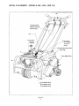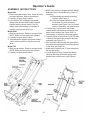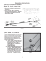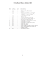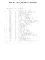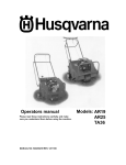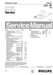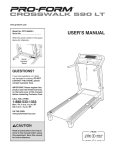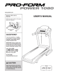
1
Operators & Parts
Manual
MANUAL NO. 107999 REV. IR (10/17/02)
MODELS:
B124
B130
B130A
B142
B424
H424
H424G
B530A
H530A
H530AG
H742
H742G
Lawn Aerators
Section 1 · Operator’s Guide
Page
Specifications ................................................................................................. 3
Features and Controls ................................................................................. 4-6
General Information ........................................................................................ 7
Safety Procedures .......................................................................................... 7
Safety and Instruction Decals ........................................................................ 8
Decal Placement ............................................................................................ 9
Assembly Instructions .................................................................................. 10
Section 2 · Operating Instructions
Page
Aeration Tips ................................................................................................ 11
Before You Start ........................................................................................... 11
Aerating ........................................................................................................ 11
Throttle Adjustment (Model 742 Honda engine only) ..................................... 11
Rear Wheel Adjustment ................................................................................ 12
Turning and Maneuvering .............................................................................. 13
Operating on Hills ......................................................................................... 13
Section 3 · Maintenance and Service Instructions
Page
Transporting the Husqvarna Aerator .............................................................. 14
Cleaning and Washing ................................................................................. 15
Two Minute Warning ..................................................................................... 15
Storage ......................................................................................................... 15
Preventative Maintenance Schedule
Inspection Schedule ......................................................................... 15
Lubrication Schedule ........................................................................ 15
Tine Wear ........................................................................................ 16
Service
Engine Service & Maintenance .................................................... 16
Drive Train
Engine Removal and Replacement ................................................... 16
Drive Belt Replacement and Adjustment ........................................... 16
Clutch Cable Removal and Replacement .......................................... 17
Throttle Cable Replacement (Model 742 Honda Engine Only) .......... 17
Chain Removal and Replacement ..................................................... 17
Adjusting Chain Tension ................................................................... 18
Handle
Inspection ........................................................................................ 18
Adjustment ....................................................................................... 18
Wheels
Drive Wheel Shaft Removal and Replacement .................................. 18
Rear Wheel Removal and Replacement ........................................... 19
Tine andTine Shaft
Tine Replacement ............................................................................ 19
Tine Shaft Bearing Removal and Replacement ................................. 19
Free Wheeling Tine Assembly Removal and Replacement ............... 20
Unit Assembly and Parts Diagrams
Model 424 ................................................................................... 21-25
Model 530A ................................................................................. 26-33
Model 742 ................................................................................... 34-39
Section 4 · General Product Information
Page
Warranty ...................................................................................................... 41
WARNING: Engine exhaust, some of it’s constituents, and certain vehicle components
contain or emit chemicals known to the State of California to cause cancer and birth defects
or other reproductive harm.
Operator’s Guide
SPECIFICATIONS
A) POWER UNIT
Engine
Clutch
Primary drive
Secondary drive
Gear reduction
B) WHEELS
Bearings
Rear tires
Front tire
C) AERATION
Tines
Aeration width
Hole pattern
Core depth
Holes per sq ft
Working speed
Productivity
D) WEIGHTS
Net weight
Shipping weight
Removable weights
E) DIMENSIONS
Height
Height overall
Length
Length overall
Width
Shipping carton
424
3.5HP Briggs I/C
(2.6kw)
4HP Honda (3kw)
Belt tensioner
One V-belt (A-44”)
Permalube Chain
6:1
530A
3.5HP Briggs I/C
(2.6kw)
4HP Honda (3kw)
Belt tensioner
One V-belt (A-44”)
Permalube Chain
6:1
742
3.5HP Briggs l/C
(2.6kw)
4HP Honda (3kw)
Belt tensioner
One V-belt (A-44”)
Permalube Chain
6:1
FRONT – ¾” (1.9 cm)
sealed
ball bearings with
stamping kit
REAR - ¾” (1.9 cm)
roller bearing
8” x 2” (20 x 5cm)
solid rubber
10” x 6” (25 x 15cm)
semi-pneu.
FRONT – ¾” (1.9 cm)
sealed
ball bearings with
stamping kit
REAR - ¾” (1.9 cm)
roller bearing
8” x 2” (20 x 5cm)
solid rubber
10” x 6” (25 x 15cm)
semi-pneu.
FRONT – ¾” (1.9 cm)
sealed
ball bearings with
stamping kit
REAR - ¾” (1.9 cm)
roller bearing
8” x 2” (20 x 5cm)
solid rubber
10” x 6” (25 x 15cm)
semi-pneu.
¾” - (1.9 cm)
open spoon tine.
24 per unit
17.5” (44.5 cm)
4.4” x 6.5"
(11.2 x 16.5cm)
Up to 3” (7.6 cm)
6.7
250 ft/min (4.57 km/h)
Up to 23,000 sq ft/hr
(2137 m2/h)
¾” - (1.9 cm)
open spoon tine.
30 per unit
19” (48.3 cm)
3.8” x 6.5”
(9.7 x 16.5cm)
Up to 3” (7.6 cm)
7.7
250 ft/min (4.57 km/h)
Up to 25,000 sq ft/hr
(2323 m2/h)
¾” (1.9 cm)
open spoon tine.
42 per unit
25.5” (64.8 cm)
3.6” x 6.5”
(9 x 16.5cm)
Up to 3” (7.6 cm)
8.1
290 ft/min (5.3 km/h)
Up to 40,000 sq ft/hr
(3716 m2/h)
265 Ibs (120 kg)
209 lbs (132 kg)
2 x 36 Ibs (16.3 kg)
288 Ibs (131 kg)
355 Ibs (161 kg)
2 x 36 Ibs (16.3 kg)
420 Ibs (191 kg)
487 Ibs (221 kg)
2 x 36 Ibs (16.3 kg)
28" (71.1 cm)
w/handle folded
49.5" (126 cm)
40" (101.6 cm)
w/handle folded
48" (122 cm)
26.5" (67.3 cm)
37” (94cm)
w/ handle folded
51.5 (130.8cm)
39.5 (100.3cm)
w/ handle folded
57.5 (146.1cm)
29.75” (75.6cm)
28" x 29" x 43"
(71 x 74 x 109 cm)
41” x 34” x 30”
(104 x 86 x 76cm)
28” (71 1cm)
less handle
52” (132cm)
33”(83.8cm)
less handle
54” (137cm)
38” (96.5cm),31”
(78.74cm) w/o wls.
41” x 34” x 30”
(104 x 86 x 76cm)
3
Operator’s Guide
MODEL 424 - FEATURES AND CONTROLS
Figure 1
4
Operator’s Guide
MODEL 530A - FEATURES AND CONTROLS
Clutch Control
Rear Wheel
Control Handle
Depth/Stability
Control Knob
Handle
Stops
Folding Handle
Locking Cam
Drive Guard
Engine
Guard
Removable
Weight
Removable
Weight
Adjustable
Rear Wheel
Powered
Front Wheel
Note: Serial number is located on the rear of the housing.
Figure 2
5
Operator’s Guide
MODEL 742 - FEATURES AND CONTROLS
Figure 3
6
Operator’s Guide
SAFETY PROCEDURES
GENERAL INFORMATION
This manual will assist you in the safe operation
and proper maintenance of your Husqvarna
equipment. Read it thoroughly before attempting
to operate the machine. Call your dealer or
Husqvarna if additional information is required.
DO:
• Read all maintenance and service instructions
before attempting work.
• Read engine manufacturer’s operating and
maintenance instructions.
• Remove spark plug wire before commencing
service.
• Inspect lawn to be aerated and remove rocks,
wire, string and other objects that might present
hazard before starting.
• Indentify and mark all ground objects to be
avoided, such as sprinkler heads, stakes, water
valves, clothes line anchors, etc.
• Use machine for lawn aeration only.
• Keep unsupervised children away from the
equipment.
• Adopt safe lifting and moving techniques when
loading/unloading and moving the equipment.
• Make sure all decals are in place.
The following safety symbols are used
throughout the manual to alert you to information
about unsafe actions or situations:
DANGER indicates immediate hazards that
may result in severe injury or death.
WARNING indicates unsafe actions or
situations that may cause severe injury, death
and/or major equipment or property damage.
CAUTION indicates unsafe actions or
situations that may cause injury, and/or minor
equipment or property damage.
This equipment should not be modified without
the manufacturer’s prior written authorization.
Doing so may not only affect the equipment’s
performance and durability, but also create
safety hazards for the operator and the
surroundings. Warranty will be void if changes
are made to the equipment without the
manufacturer’s prior written authorization.
DO NOT:
• Do not run engine while servicing.
• Do not use on any surface other than grass.
• Do not operate on slopes exceeding 35%
grade.
• Do not place hands or feet near moving or
rotating parts.
• Do not lift Model 424 alone.
• Do not lift Model 530A.
• Do not lift Model 742
• Do not run engine in an unventilated space.
• Do not run engine while servicing. Remove
spark plug wire before commencing service.
• Do not smoke or allow open flames or sparks
near unit, and always stop the engine when
refueling
• Do not remove guards when operating.
• Do not modify this equipment.
• Do not use this equipment for purposes other
than lawn aeration.
7
SAFETY AND INSTRUCTION DECALS
The following decals are found on Model 424,530 and 742 aerators. If any are missing or not
legible, replace them before operating aerator.
8343 Decal kit, Model 424
7630 Decal kit, Model 530A
7404 Decal kit, Model 742
A - Model 424 only (1 EA)
C - Model 742 only (1 EA)
B - Model 530A only (1 EA)
D - Models 424, 530A & 742 (2
EA)
F - Models 424, 530A & 742 (1
EA)
E - Model 742 only (2 EA)
G1 - Model 530A (1 EA)
G2 - Model 424 & 742 (1 EA)
I - Models 424, 530A & 742 (1 EA)
H - Models 424, 530A & 742 (1 EA)
K - Models 530A & 742 (1 EA)
424 (2 EA)
8
J - Models 424, 530A & 742 (1 EA)
DECAL PLACEMENT - MODELS 424, 530A AND 742
G2
Throttle Cable
(Model 742 with
Honda only)
G1
H (on deck
behind
engine)
F (on back
of housing
over tine
rotor)
K (for Models 424 & 742
logo only)
I
J
E (for Model 742)
K
D
A (for Model 424)
B (for Model 530)
C (for Model 742)
Figure 3
9
Operator’s Guide
ASSEMBLY INSTRUCTIONS
Model 424
1. Remove wooden blocks. Note: Watch for nails
and wood splinters. Wear eye protection.
2. Carefully cut open side of carton.
3. Lawn Aerator 424 is shipped with handle
folded. Rear wheel control handle strapped
together with the clutch control. First cut
straps, then unfold handle. Lock handle in
position using the cam lock lever.
Model 530A
1. Wear eye protection. Remove wooden blocks.
NOTE: Watch for nails and wood splinters.
2. Carefully cut open side of carton.
3. Lawn Aerator is shipped with handle folded.
Lock handle in position using the cam lock
lever.
Model 742
1. Wear eye protection. Remove wooden blocks.
NOTE: Watch for nails and wood splinters.
2. Carefully cut open side of carton.
3. AR25 Lawn Aerator is shipped with the handle
detached. Mount the handle using 2 each ½”
wrenches.
(A) Slide handle onto handle mounting
brackets (see Figure 4).
(B) Insert and tighten fasteners, which
are located on handle mounting
brackets (see Figure 5-A). For further
detail on assembly, see parts section.
4. Connect top of control rod to rear wheel
control handle with fasteners located on rear
wheel control handle (see Figure 5-B) For
further detail on assembly, see parts manual.
5. Connect bottom of control rod to OUTER side
of lever on the torque arm using the fastener
assembly (see Figure 5-C).
6. Run the clutch cable through the guide hole in
the handle bracket support bar located at rear
of the deck (see Figure 4).
7. Attach end of cable to the “S” hook located on
the belt idler pulley.
8. (Honda Engines Only) Connect the throttle
cable by attaching the throttle spring to the
throttle/clutch control lever. (see Figure 4)
Figures 4
Figures 5
10
Operating Instructions
AERATION TIPS
Should I water before aerating?
Best aerating condition is a soft and moist
ground. If you are unsure of the ground
conditions, as in soil with high clay content, a
simple test will determine whether it is
necessary to water before aerating. Using a
garden hand spade or a large screw driver, you
should be able to drive the tool in the ground 2 to
3 inches with little effort. If you are unable to do
so, then watering the lawn a day before aerating
is necessary.
When should I use the removalole weights?
Soil conditions will dictate whether extra
machine weight is needed for effective coring
action. The weights are provided to give you
added control, and greater tine penetration.
BEFORE YOU START
1. Make sure that engine oil is at engine
manufacturer’s recommended level (refer to
engine manual). Be sure gear reduction oil is
at engine manufacturer’s recommended level.
Make sure the machine is level when filling
with oil.
2. With the folding handle in its operating
position, lock the handle cam lock (Models
424 & 530A only).
3. Rear wheel control handle must be pulled up
so rear wheels are all the way down.
4 Insert weights if needed.
5. Be sure handle is properly mounted.
6. Test clutch handle to insure clutch releases
freely.
7. The engine top speed is preset by the engine
manufacturer. Consult the engine
manufacturer’s manual for directions to
adjust the governor and carburetor if speed is
not within correct range.
8. 742 Honda Engines Only: The throttle cable
has been installed by the factory, however
throttle spring needs to be connected to
throttle/clutch control lever (see Figure 4).
AERATING
1. Start engine and adjust throttle setting to
provide a comfortable walking speed and
maintain control of the equipment at all times.
2. Adjust depth control knob (see Figure 1 or 2)
to desired depth. Coring depth decreases by
turning the knob clockwise.
NOTE: by raising the rear wheels all the way
up (to obtain maximum coring depth) you will
reduce the unit’s stability but increase length
of core.
3. Push down the rear wheel control handle to
lower aerating tines into the ground (rear
wheels will rise).
4. Push down on handle bar for better tine
penetration and maneuverability (front wheel
will rise).
5. Engage clutch control.
6. Adjust engine throttle setting, if needed, for
comfortable speed.
7. To stop, release clutch control.
CAUTION!
NEVER cross hard objects or surfaces
(sidewalks, driveways, stepping stones,
etc.) with tines down.
CAUTION!
Be sure clutch cable is routed properly.
11
Operating Instructions
THROTTLE CABLE ADJUSTMENT.
Model 742 (Honda Engine Only)
1. Start engine and allow it to reach operating
temperature.
2. Adjust the throttle cable at the adjuster
bracket by turning the adjuster nut. Tightening
will increase engine speed, loosening will
reduce engine speed.
NOTE: A properly adjusted throttle will slightly
increase engine speed as the clutch engages.
• If the clutch engages too soon, the engine
will stall.
• If the engine speed is too high, the gradual
controlled start is lost.
Figure 6
REAR WHEEL ADJUSTMENT
The rear wheel depth/stability control knob (see
Figure 7) allows adjustment for better stability
and maneuverability by turning knob clockwise.
Adjusting for depth by turning knob counter
clockwise determines the length of the cores
pulled in the following ways:
(A) The rear wheels can be adjusted to the
level you desire so you can control the
penetrationof the tines to within a
fraction of an inch. The length of the
cores pulled can be
controlled accordingly.
(B) With the rear wheels adjusted to the full
up position, you will obtain maximum
tine penetration. Pushing down on the
machine’s handle bars will put most of
the weight of the machine on the tines.
In this configuration you will pull the
longest cores. (Front wheel will rise).
Figure 7
12
Operating Instructions
NOTE: Adjusting for greater stability will shorten
the length of the cores you pull. You will gain
greater side-to-side stability (see below
“Operating on Hills.” Adjustments for greater
stability will also improve maneuverability during
aeration.)
OPERATING ON HILLS
WARNING!
DO NOT operate on hills exceeding 35%
grade.
TURNING AND MANEUVERING
THE AERATOR
Gradual maneuvering while aerating can be
accomplished by simply guiding the machine.
We recommend that you adjust your engine’s
speed control to allow for a comfortable walking
speed. This will also help you maintain complete
control while working in tight spaces. Adjusting
for more stability (with the rear wheels lowered,
reducing tine penetration) will make turning
easier.
When reversing direction or making sharp turns
two methods of turning can be used. Select the
safest and most comfortable method for the
conditions you face:
(A) Release clutch control handle, pull up rear
wheel control handle, then pivot machine on
rear wheels to turn.
(B) Release clutch control handle, lift handle bar
and pivot machine on front wheel.
Figure 8
This unit is not designed to be used on steep
slopes. Be aware that when operating on hills
the
tilt of the aerator will cause the machine’s center
of gravity to shift to the downhill side of the
machine. Under these circumstances you may
experience:
(A) The need to exert a greater effort to
steer and maintain the balance of the
machine.
(B) Uneven tine penetration, when
operating across a hill. Due to the shifted
center of gravity
the downhill tines will penetrate to the
maximum depth, while uphill tines may
not.
WARNING!
This method is NOT recommended when
operating on hills. (See next section.)
WARNING!
In extreme situations (very steep hills)
the machine may be so unbalanced, that
it may present the danger of rolling over.
13
Operating Instructions
TRANSPORTING THE BLUEBIRD
AERATOR
When operating on hills you should
consider the following:
(A) Operate the machine up and down the
hills rather than across them.
(B) Use the rear wheel depth/stability control
knob to set the rear wheels for extra
stability. This can be a great benefit
when you do choose to run the aerator
across a hill. An added benefit of using
the rear wheel depth control when
aerating across a hill is that you will
improve the consistency of the cores
pulled from the uphill tines when
compared to those pulled by the
downhill tines.
(C) Removing the downhill weight reduces
roll-over risk and maintains consistent
core plug length. (See Figure 9)
(D) Remove remaining weight from downhill
side to uphill side after each pass when
operating across hills.
WARNING!
MODEL 424
The BlueBird 424 Aerator has three convenient
features to assist you in transporting the unit in
your pick-up truck, van and even in some car
trunks. Those features are: removable weights,
a folding handle and convenient lifting handles on
the sides of the machine. The features are
provided for your optional use and can be of
great benefit when required.
Removable Weights
• Unlatch weight locks.
• Grab weight handles and pull the weights
from the machine.
Note: Weight 36 lb/16 kg each.
Folding Handle
• Release handle cam lock.
• Fold handle forward over the engine until it
is resting on the engine guard.
Lifting Handles
Lifting handles are located on both sides of the
aerator, to allow two people to lift the unit.
NEVER disengage tines from ground
when travelling up or down hill. ONLY
disengage on flat surface.
CAUTION!
Avoid back or muscle injury! Use safe
lifting techniques, DO NOT exceed your
physical limitatons. DO NOT attempt to lift
ALONE. Weight 193 lb/88 kg w/o weights.
MODELS 530A AND 742
The removable weights are for side hill stability
and tine penetration as applicable.
CAUTION!
DO NOT lift aerators.
With the weights in place, these models are
designed for easy loading and unloading on
ramps and trailers. The treaded front wheel
provides increased control during transport. Use
engine power to load unit.
Figure 9
14
Maintenance and Service Instructions
CLEANING AND WASHING
Regular cleaning, washing and lubricating will
prolong the service of your machine.
NOTE: Use care with power washers to avoid
damage to Warning Decals, Operator Instruction
Labels, Bearings,Chain and Engine. Limit direct
spray on these items.
DO NOT EXCEED 1000 PSI WATER
PRESSURE FOR CLEANING
TWO MINUTE WARNING
STORAGE
1. Refer to engine manufacturers instructions for
engine storage information.
2 Clean machine.
3. Cover all scratches with touch up paint.
4. Lubricate according to Lubrication Schedule.
5. Lightly oil or mil board tines to inhibit rust.
6. Store unit with machine in transport position.
7. Handle may be folded.
8. Covered or indoor storage is recommended.
Aerators may be tipped on their engine guard for
cleaning and access for no more than 2
minutes. Engine damage may result from
gasoline draining into the crankcase if prolonged.
See engine manufacturers operating and
maintenance instructions.
PREVENTATIVE MAINTENANCE SCHEDULE
A) Inspection Schedule
Item
• Engine Oil
• Gear box oil
• Engine air cleaner
• Clutch & cable
• Chain tension
• Belt wear & tension
• Tine wear & condition
• Fasteners
• Sprockets & set screws
• Frame condition
• Decals
Out of Box
•
•
•
•
•
•
•
•
•
•
•
First 5 hrs.
Every 10 hrs
•
•
Each Use
•
•
•
•
•
•
•
B) Lubrication Schedule
Item
• Engine
• GearBox
• Rear wheels
• Chain
• Tines
• Linkage
Lubricant
Every 20 hrs
Oil, see engine
Owner’s manual
Oil, see engine
Owner’s manual
Lithium based grease
Graphite dry lubricant
(Aerosol)
Light machine oil
30W oil
•(*)
Every 60 hrs
As Required
•
Storage
•
•
•
•
•
•
•
•
(*) after each pressure wash or steam cleaning
15
Maintenance and Service Instructions
TINE WEAR
After your BlueBird Aerator has been used for
sometime, the tines will wear. When this
happens their aerating performance will
diminish. Inspect tines using the drawing,
replace when at minimum length or before.
(Tines are 5” when new.)
Drive Belt Replacement and Adjustment
1. Turn off engine and remove the drive guard
cover.
2. Remove V-belt.
3. Inspect condition of V-pulleys and replace if
necessary.
4. Check V-pulley alignment by looking down the
belt with clutch engaged. Be sure both
V-pulleys are directly in line with each other.
Correct their alignment if they are not.
5. Install new belt over small V-pulley first, then
over the large V-pulley. (see Figure 11).
Figure 10
ENGINE SERVICE AND
MAINTENANCE
Follow the engine manufacturers maintenance
instructions. Should any malfunction occur with
the engine during the warranty period, take it to
an Authorized Service Dealer. DO NOT tear
down the engine, as this may void the Engine
Manufacturers Warranty.
NOTE: Refer to engine manufacturers owners
manual for all engine service information.
DRIVE TRAIN
Engine, Removal and Replacement
1. Remove weights for access.
2. Remove drive guard.
3. Remove V-Belt.
4. Remove engine bolts.
5. Lift engine from unit.
NOTE: Model 742 aerators equipped with
optional Honda engines have 2 pairs of shim
plates under the engine.
6. Remove and retain V-pulley and key.
7. Replacement procedure opposite of removal.
8. Adjust drive belt and align V-pulley, see
following section.
Figure 11
NOTE:Many parts including the drive belt on
your BlueBird Aerator are made
specificlly for Husqvarna to give many
hours of use. Replace all parts with
genuine BlueBird parts to obtain
maximum performance and life.
6. Insure V-belt is inside both keeper arms.
7. Check that the V-belt clears the top belt
keeper arm when idler is pulled tight.
Check that the aerator rolls freely (with handle
folded on Models 424 and 530A), with the belt
slack. Adjust the keeper, or clutch cable length
if necessary.
8. For clutch adjustments refer to next section
(Clutch Cable Removal and Replacement).
9. Replace drive guard.
16
Maintenance and Service Instructions
Clutch Cable Removal and Replacement
1. Turn off engine and remove old clutch cable.
2. Route new cable through the hole at the rear
of housing.
3. Attach clutch cable to the bracket on the
spring on the idler assembly, then connect
opposite end of cable to the S hook.
4. Adjust cable to obtain ¾” to1 ¼” extension of
the clutch spring when clutch is engaged.
(see Figure 12).
4. Attach the new adjuster bracket to the spring
on the throttle/clutch lever.
NOTE: As the cable length increases between
the cable screw and adjuster nut the
engine speed decreases. If engine speeds
too low, the engine will stall as the clutch
engages. As the cable length decreases
between the cable screw and adjuster
nut, the engine speed will increase. If
engine speed is too high, the controlled
start will be lost.
Chain Removal and Replacement
1. Turn off engine.
2. Remove the drive guard.
3. Loosen chain idler adjustment bolt and lock nut.
4. Remove master link and remove chain.
5. Inspect and align sprockets. (see Figure 13).
Check set screws. (Double set screws for
wheel and rotor sprocket).
Figure 12
Throttle Cable Removal and
Replacement:
Model 742 Honda Engine Only
1. Before removing your old cable measure the
amount of cable extending past the cable
screw.
2. Remove the old throttle cable and route the
new cable through the guide hole at the rear
of the housing.
3. Insert the new cable through the cable screw
to the measurement obtained in step 1 and
tighten. This is only an approximate setting,
some additional adjustment may be required,
see page 12 for cable adjustment.
Figure 13
6. Install new chain from top (drive sprocket
side) and route in accordance with Figure 14.
NOTE: Chain is most easily connected just
behind the fiont drive wheel sprocket.
7. Install master link with pin plate on engine
side of chain with keeper plate installed on
outboard side. Install clip with split to front of
machine.
17
Maintenance and Service Instructions
Figure 14
Adjusting Chain Tension
1. Turn engine off.
2. Remove drive guard, loosen lock nut on idler
adjustment bolt.
3. Turn idler adjustment bolt to adjust tension to
allow 1/8" to 1/4" movement at the center
point between the wheel sprocket and the
rotor sprocket (see Figures 14 and 15).
4. Tighten lock nut.
NOTE: Husqvarna recommends the replacement
of sprockets when replacing drive chain.
HANDLE - MODEL 424 and 530A ONLY
Inspection
1. The handle cam lock must lock shut under
moderately heavy hand pressure. Handle
frame should be tightly secured to the aerator
body.
2. Check the cam rod lock nut. If it turns freely by
hand when cam is released, the locking
strength of the nut has been relieved and the
nut must be replaced to maintain the security
of the Iock.
Adjustment
With the handle in the operating position, slowly
tighten the cam rod lock nut (1/4 turn at a time)
until the cam handle locks with moderately heavy
hand pressure.
IMPORTANT: excessive adjustment of the lock
nut will damage the cam rod. ALWAYS replace a
free spinning nut to avoid unwanted loosening of
the handle. For smooth operation of the cam,
apply a small amount of grease on the cam edge.
WHEELS
1. Turn off engine and empty all fuel from the fuel
tank.
2. Remove weights and drive guard.
3. Loosen the Iock nut on adjustment screw to
Ioosen the chain. Remove master link and
chain.
4. Tip the front end up to let the aerator rest on its
handle. The front wheel will be approximately 1
foot off the ground.
CAUTION!
Secure handle to prrevent aerator from
tipping.
Figure 15
5. Remove the wheel shaft bearing bolts (4 on the
424 and 530A and 6 on the 742).
6. Remove the wheel axle assembly.
Drive Wheel Shaft Removal and Replacement
7. Pull sprocket and bearing from shaft. NOTE:
Sprocket is double set screwed. To remove
the bearings, you must first remove the collar
by loosening the set screw, then insert pin
punch into the hole next to the set screw and,
using a hammer, with moderate striking, hit
18
Maintenance and Service Instructions
collar so that it rotates in the opposite
direction the wheel would normally turn. If
bearings are rusted in place they will have to
be replaced along with the wheel and shaft.
8. Install bearings and sprocket loosely onto the
shaft. Models 424 & 530A: hub side away
from wheels. Model 742 has 3 bearings.
Wheel bearings should have hubs facing
away from wheel. Wheel shaft bearing
should have hub facing away from sprocket.
9. Bolt bearings into place.
10. Center the wheels between the wheel
opening and the housing. Lock the collars in
place and tighten set screws.
11. Align and tighten the sprocket (there are
double set screws stacked two in each hole)
use blue loctite with the key in place.
12. Replace the chain following procedures in
section “Chain Removal and Replacement.(see
page 17).
13. Adjust chain per section “Adjusting Chain
Tension” and replace drive guard. (see page
18).
Rear Wheel Removal and Replacement:
Models 424 & 530A
1. Make sure unit is on level ground and engine
is turned off.
2. Lower the rear wheel control handle to let the
aerator rest on the tines.
3. Turn the rear wheel depth/stability control
knob to adjust the rear wheels for minimum
depth clockwise (more stability).
4. Remove the axle nut. Pull the axle bolt, then
the wheel from the wheel carriage.
5. Install a new wheel with grease fitting facing
out, with seals carefully in place on the wheel
bushing.Insert axle bolt through wheel and
wheel lift frame. Use washer and lock nut,
tighten firmly.
6. Grease wheel bearings.
4. Remove the hairpin cotter pin. (see Figure 16)
5. Slide the wheel assembly off the machine.
(see Figure 16)
6. Install hairpin cotter pin into the axle when
removed to prevent loss.
Removable Wheel - Model 742 Only
Figure 16
TINE AND TINE SHAFT
Tine Replacement
1. Turn off engine and remove weights.
2. Fold handle on the 424 and 530A Models.
3. Place on workbench (Model 424 only) and
chock wheels.
3. Note direction of tine bolt. Reinstall the bolt
facing in the same direction on the Model
424 to avoid contact with weights.
4. Remove and replace tines by loosening stop
bolt. Remove retaining bolt and old tine, insert
new tine and fasten with retaining bolt in the
same direction as it was removed. When all
tines are replaced, tighten stop bolts.
NOTE: Replace worn lock nuts to insure that
bolts will hold tines in place.
Tine Shaft Bearing Removal and
Replacement
1. Turn off engine and remove weights.
2. Remove drive guard cover.
Rear Wheel Removal and Replacement:
3. Fold handle for better access to tines (on
Model 742
Models 424 & 530A only).
4. Elevate approximately 4", block and chock
1. Make sure unit is on level ground and the
rear wheels.
engine is shut off.
5. Manually cycle the drive chain for acess to
2. Lower the rear wheel control handle to let the
master link.
aerator rest on the tines.
6. Turn chain idler adjustment screw counter
3. Turn the rear wheel depth/stability control
clockwise to loosen the chain.
knob to adjust the rear wheels for minimum
7. Remove the master link and free rotor
depth clockwise for more stability.
sprocket.
19
Maintenance and Service Instructions
8. Remove the tine rotor shaft bearing bolts (4).
9. Remove chain scaper bolts (2) and chain
scraper (on Model 424 only).
10. Remove the rotor shaft assembly.
11. Remove outer rotor bearing by loosening the
set screw in the collar.
Figure 17
12. Unlock collar (best accomplished by using a
hammer and pin punch). Insert pin punch
intothe hole next to the set screw and, using
the hammer, with moderate striking, hit collar
so that it rotates in the opposite direction the
rotor would normally turn.(see Figure 17)
13. Reverse these steps to reinstall.
14. Refer to sections “Chain Removal and
Replacement” and “Adjusting Chain Tension”
for chain replacement and adjustment of
chain tension. (see page 18).
Free-Wheeling Tine Assembly Removal and
Replacement
Complete steps 1 through 12 in previous
section, then proceed with the following:
1. After the bearing is off the rotor, unlock the
inner bearing that secures the tine assembly.
2. Remove outer free-wheeling tine assembly.
3. Place the new rotor assembly beside the old
assembly so that you have a pattern to follow
indicating the correct direction which the new
tines are to be installed. You can also refer to
the tines on the fixed tine assembly as an
example of proper assembly.
4. Once the tines are installed on the
free-wheeling assembly, re-install the inner
and outer bearing assemblies on the
free-wheeling assembly with the bearing
hubs facing toward the fixed tines. Make sure
that the inner bearing has a locking collar.
Hand tighten the nuts only.
5. Slide the new free-wheeling tine assembly on
the shaft making sure that the tine direction
matches the direction of the fixed tine
assembly. The bearing with the locking collar
faces the fixed tines and butts up against the
shoulder of the shaft.
6. Tighten the four nuts on the bearing
assemblies.
7. Lock the bearing collar in place with the
hammer and punch making sure the collar
locks in the same direction as the rotation of
the rotor.
8. Replace outer shaft bearing and re-install the
entire rotor assembly by reversing steps 1
through 12 in previous action. Instructions
are for one side. Both are procedurally
identical.
20
Parts Main Frame - Model 424
ITEM PART NO.
1 ...... 7144
2 ...... 7154
3 ...... 7186
4 ...... 7200
5 ...... 7201
6 ...... 7202
7 ...... 7203
9 ...... 0729
.......... 7227
QTY.
DESCRIPTION
.................2 ........... WEIGHT, 36 LBS., SOLID STEEL
.................1 ........... hOUSING W/DECALS
.................1 ........... DRIVE GUARD W/DECALS
.................1 ........... DRIVE GUARD FASTENER KIT
.................2 ........... LATCK KIT, WEIGHT W/HARDWARE
.................1 ........... SCRAPER KIT, CHAIN W/HARDWARE
.................1 ........... PLATE KIT, FOR HONDA ENGINE
............................... PAINT, BLUE, 1 QT.
.................1 ........... DECAL KIT, 424, (NOT SHOWN)
21
Parts Handle and Control - Model 424
ITEM PART NO.
1 ...... 0034
2 ...... 5129
3 ...... 5256
4 ...... 7149
5 ...... 7151
6 ...... 7174
7 ...... 7189
8 ...... 7191
9 ...... 7221
10 ...... 7222
11 ...... 7223
12 ...... 7224
13 ...... 7225
14 ...... 7226
QTY.
DESCRIPTION
.................2 ........... GRIP, CLUTCH
.................1 ........... SPRING, CLUTCH
.................1 ........... CAM, LOCKING
.................1 ........... CLUTCH CONTROL W/GRIPS
.................1 ........... HANDLE W/GRIPS
.................1 ........... HANDLE, CONTROL, REAR WHEEL
.................1 ........... CLUTCH CABLE
.................1 ........... GRIPS, PAIR
.................1 ........... FASTENER KIT, CLUTCH CONTROL TO HANDLE
.................1 ........... CLUTCH CABLE KIT
.................1 ........... PIN KIT, REAR WHEEL CONTROL HANDLE
.................1 ........... CONTROL ROD KIT, REAR WHEEL
.................1 ........... CAM ROD KIT, W/CAM
.................1 ........... CAM ROD KIT, WITHOUT CAM
22
Parts Rear Wheel - Model 424
ITEM PART NO.
QTY.
DESCRIPTION
1 ...... 0048 .................2 ........... BEARING, ROLLER W/BUSHING & SEALS
2 ...... 7107 .................2 ........... LIFT LINK
3 ...... 7133 .................1 ........... TORQUE ARM, DEPTH ADJUSTMENT
4 ...... 7148 .................1 ........... WHEEL CARRIAGE, AXLE
5 ...... 7163 .................1 ........... KNOB, DEPTH/STABILITY
6 ...... 7195 .................2 ........... SPRING, AXLE
7 ...... 7213 .................1 ........... CONTROL KIT, DEPTH/STABILITY
8 ...... 7214 .................1 ........... KNOB SPRING KIT, DEPTH/STABILITY
9 ...... 7215 .................1 ........... BRACKET KIT, DEPTH/STABILITY
10 ...... 7216 .................2 ........... FASTENER KIT, TORQUE ARM/HOUSING
11 ...... 7217 .................4 ........... FASTENER KIT, LINKAGE
12 ...... 7218 .................2 ........... FASTENER KIT, CARRIAGE/HOUSING
13 ...... 7219 .................2 ........... BOLT KIT, REAR WHEEL
14 ...... 7220 .................2 ........... WHEEL KIT, REAR W/ROLLER BEARINGS,
................................................... BUSHING & SEALS
23
Parts Power Train & Tine Rotor - Model 424
24
Parts Power Train & Tine Rotor - Model 424
ITEM PART NO.
QTY.
DESCRIPTION
1 ...... 0301 .................1 ........... SPROCKET, JACKSHAFT, W/KEY & SPACER
2 ...... 0302 .................1 ........... SPROCKET, WHEEL, W/SET SCREWS & KEY
3 ...... 0303 .................1 ........... SPROCKET, ROTOR, W/SET SCREWS & KEY
4 ...... 0307 .................1 ........... MASTER LINK FOR 0308
5 ...... 0308 .................1 ........... CHAIN, #40 PERMA LUBE ROLLER
6 ...... 0315 .................4 ........... BEARING, 3/4" W/LOCK COLLAR
7 ...... 0317 .................2 ........... BEARING, 1" W/LOCK COLLAR
8 ...... 0328 .................1 ........... V-PULLEY, A-4" W/SET SCREWS & KEY
9 ...... 0332 .................1 ........... V-PULLEY, A-10" W/SET SCREWS & KEY
10 ...... 0336 .................1 ........... V-BELT, A-44" SPECIAL
11 ...... 5185 .................4 ........... STAMPING KIT W/FASTENERS (FOR 3/4" BEARING)
12 ...... 5786 .................2 ........... STAMPING KIT W/FASTENERS (FOR 1" BEARING)
13 ...... 7157 .................1 ........... ROTOR SHAFT, TINE WITHOUT BOLTS
14 ...... 7204 .................1 ........... FASTENER KIT, ENGINE
15 ...... 7205 .................1 ........... BELT KEEPER KIT
16 ...... 7206 .................1 ........... IDLER ARM KIT, PULLEY
17 ...... 7207 .................1 ........... IDLER PULLEY KIT
18 ...... 7208 .................1 ........... IDLER ARM KIT, CHAIN
19 ...... 7209 .................1 ........... IDLER SPROCKET KIT, CHAIN
20 ...... 7210 .................1 ........... FRONT WHEEL & SHAFT KIT
21 ...... 7211 ..................1 ........... TINE SET, CLOSED SPOON, 24 EACH
.......... 7112 ..................4 ........... TINE SET, CLOSED SPOON, 6 EACH
22 ...... 7212 .................1 ........... TINE/SPIKE FASTENER KIT, 48 EA. BOLTS & NUTS
.......... 7103 .................4 ........... TINE/SPIKE FASTENER KIT, 12 EA. BOLTS & NUTS
23 ...... 7232 .................1 ........... JACKSHAFT, W/KEY
24 ...... 7311 ..................1 ........... SPIKE SET, 24 EACH
25 ...... 7199 .................1 ........... CE CHAIN GUARD (FOR EUROPEAN MODELS)
25
Parts Main Frame - Model 530A
26
Parts Main Frame - Model 530A
ITEM PART NO.
1 ...... 7600
2 ...... 7601
3 ...... 7602
4 ...... 7200
6 ...... 0729
.......... 7630
QTY.
DESCRIPTION
.................2 ...........
.................1 ...........
.................1 ...........
.................1 ...........
...............................
.................1 ...........
WEIGHT, 36 LBS., SOLID STEEL
HOUSING W/DECALS
DRIVE GUARD W/DECALS
DRIVE GUARD FASTENER KIT
PAINT, BLUE, 1 QT.
DECAL KIT, 530, (NOT SHOWN)
27
Parts Handle & Control - Model 530A
1
2
6
14
15
6
23
6
9
7
12
19
11
5
4
15
20
3
8
15
22
21
10
6
16
20
15
17
6
18
13
28
Parts Handle & Control - Model 530A
ITEM PART NO.
QTY.
DESCRIPTION
1 ...... 0033C ...............2 ........... GRIPS, PAIR
2 ...... 0143 .................2 ........... SCREW, 5/16-18 X 1
3 ...... 0210 .................2 ........... NUT, 5/16-18
4 ...... 0352 .................2 ........... RING, RETAINING
5 ...... 03895................2 ........... PIN, CLEVIS, 5/16 X 1.174
6 ...... 0410 .................9 ........... WASHER, 5/16
7 ...... 02005................2 ........... NUT, 10-32, FLANGE LOCK
8 ...... 200224 ..............1 ........... HANDLE, LOWER
9 ...... 0403 .................2 ........... WASHER, #10
10 ...... 200744 ..............1 ........... HANDLE
11 ...... 0034 .................2 ........... GRIP, CLUTCH
12 ...... 5129 .................1 ........... SPRING, CLUTCH
13 ...... 5256 .................1 ........... CAM, LOCKING
14 ...... 200201 ..............1 ........... CLUTCH CONTROL
15 ...... 0211 .................. 5 ........... NUT, 5/16-18, LOCKING
16 ...... 0377 .................1 ........... PIN, ROLL, 1/4" X 3/4"
17 ...... 12507................1 ........... ROD
18 ...... 0144 .................1 ........... SCREW, 5/16-18 X 1 1/4
19 ...... 0150 .................1 ........... SCREW, 5/16-18 X 1 3/4
20 ...... 10191................2 ........... BUSHING
21 ...... 200190 ..............1 ........... BAR, TRANSPORT LINK
22 ...... 7189 .................1 ........... CABLE, CLUTCH ????
23 ...... 10189................1 ........... SCREW, 10-32 X 1
29
Parts Rear Wheel - Model 530A
30
Parts Rear Wheel - Model 530A
ITEM PART NO.
QTY.
DESCRIPTION
1 ...... 0048 .................2 ........... BEARING, ROLLER W/BUSHING & SEALS
2 ...... 7107 .................2 ........... LIFT LINK
3 ...... 7133 .................1 ........... TORQUE ARM, DEPTH ADJUSTMENT
4 ...... 7620 .................1 ........... WHEEL CARRIAGE, AXLE
5 ...... 7163 .................1 ........... KNOB, DEPTH/STABILITY
6 ...... 7195 .................2 ........... SPRING, AXLE
7 ...... 7213 .................1 ........... CONTROL KIT, DEPTH/STABLITILY
8 ...... 7214 .................1 ........... KNOB SPRING KIT DEPTH/STABILITY
9 ...... 7215 .................1 ........... BRACKET KIT, DEPTH/STABILITY
10 ...... 7216 .................2 ........... FASTENER KIT, TORQUE ARM/HOUSING
11 ...... 7217 .................4 ........... FASTENER KIT, LINKAGE
12 ...... 7218 .................2 ........... FASTENER KIT, CARRIAGE/HOUSING
13 ...... 7621 .................2 ........... BOLT KIT, REAR WHEEL
14 ...... 7220 .................2 ........... WHEEL KIT, REAR, W/ROLLER BEARING,
................................................... BUSHING & SEALS
31
Parts Power Train & Tine Rotor - Model 530A
32
Parts Power Train & Tine Rotor - Model 530A
ITEM PART NO.
QTY.
DESCRIPTION
1 ...... 7630 .................1 ........... SPROCKET, JACKSHAFT, W/KEY & SPACER
2 ...... 0302 .................1 ........... SPROCKET, WHEEL, W/SET SCREWS & KEY
3 ...... 0303 .................1 ........... SPROCKET, ROTOR, W/SET SCREWS & KEY
4 ...... 0307 .................1 ........... MASTER LINK FOR 0308
5 ...... 0308 .................1 ........... CHAIN, #40 PERMA LUBE ROLLER
6 ...... 0315 .................4 ........... BEARING, 3/4" W/LOCKING COLLAR
7 ...... 0317 .................2 ........... BEARING, 1" W/LOCK COLLAR
8 ...... 0328 .................1 ........... V-PULLEY, A-4" W/SET SCREWS & KEY
9 ...... 0332 .................1 ........... V-PULLEY, A-10" W/SET SCREWS & KEY
10 ...... 0336 .................1 ........... V-PULLEY, A-44" SPECIAL
11 ...... 5185 .................4 ........... STAMPING KIT W/FASTENERS (FOR 3/4" BEARING)
12 ...... 5786 .................2 ........... STAMPING KIT W/FASTENERS (FOR 1" BEARING)
13 ...... 7631 .................1 ........... ROTOR SHAFT, TINE WITHOUT BOLTS
14 ...... 7204 .................1 ........... FASTENER KIT, ENGINE
15 ...... 7205 .................1 ........... BELT KEEPER KIT
16 ...... 7206 .................1 ........... IDLER ARM KIT, PULLEY
17 ...... 7632 .................1 ........... IDLER PULLEY KIT
18 ...... 7633 .................1 ........... IDLER ARM KIT, CHAIN
19 ...... 7634 .................1 ........... IDLER SPROCKET KIT, CHAIN
20 ...... 7635 .................1 ........... FRONT WHEEL & SHAFT KIT
21 ...... 7636 .................1 ........... TINE SET, CLOSED SPOON, 30 EACH
.......... 7112 .................. 5 ........... TINE SET, CLOSED SPOON, 6 EACH
22 ...... 7637 .................1 ........... TINE/SPIKE FASTENER KIT, 72 EA. BOLTS & NUTS
.......... 7103 .................5 ........... TINE/SPIKE FASTENER KIT, 12 EA. BOLTS & NUTS
23 ...... 7232 .................1 ........... JACKSHAFT, W/KEY
24 ...... 7638 .................1 ........... SPIKE SET, 30 EACH
25 ...... 7105 .................4 ........... STAMPING KIT (FOR 1" BRG.) W/NUTS & WASHERS
26 ...... 7108 .................2 ........... BEARING 1" (DOES NOT INCLUDE LOCK COLLAR)
27 ...... 7639 .................2 ........... LEFT ROTOR PLATE
28 ...... 7640 .................2 ........... RIGHT ROTOR PLATE
29 ...... 5129 .................1 ........... SPRING CLUTCH
30 ...... 7641 .................1 ........... ROTOR SHAFT, CENTER
33
Parts Main Frame - Model 742
ITEM PART NO.
1 ...... 7600
2 ...... 7400
3 ...... 7401
4 ...... 7200
5 ...... 7402
6 ...... 7203
7 ...... 7403
9 ...... 0729
.......... 7404
QTY.
DESCRIPTION
.................2 ........... WEIGHT, 36 LBS., SOLID STEEL, REMOVABLE
.................1 ........... HOUSING W/DECALS
.................1 ........... DRIVE GUARD W/DECALS
.................1 ........... FASTENER KIT, DRIVE GUARD
.................2 ........... FASTENER KIT, WEIGHT
.................1 ........... PLATE KIT, FOR HONDA ENGINE
.................2 ........... 36 LB. WEIGHT, MOUNTED
............................... PAINT, BLUE, 1 QT. CAN
.................1 ........... DECAL KIT (NOT SHOWN)
34
Parts Handle & Control - Model 742
ITEM PART NO.
QTY.
DESCRIPTION
1 ...... 0034 .................2 ........... GRIP, CLUTCH, 1 EACH
2 ...... 5129 .................1 ........... SPRING, CLUTCH
3 ...... 7149 .................1 ........... CLUTCH CONTROL, W/GRIPS
.......... 7405 .................1 ........... CLUTCH/THROTTLE CONTROL ................................................... HONDA ENGINE ONLY
4 ...... 7406 .................1 ........... HANDLE W/GRIPS
5 ...... 7174 .................1 ........... HANDLE, CONTROL, REAR WHEEL
6 ...... 7189 .................1 ........... CLUTCH CABLE
7 ...... 7191 .................1 ........... GRIPS, PAIR
8 ...... 7221 .................1 ........... FASTENER KIT, CLUTCH CONTROL TO HANDLE
9 ...... 7222 .................1 ........... CLUTCH CABLE KIT
................................................... (COMPLETE ASSY. EXCEPT #5129)
10 ...... 7223 .................1 ........... PIN KIT, REAR WHEEL CONTROL HANDLE
11 ...... 7224 .................1 ........... REAR WHEEL CONTROL ROD KIT
12 ...... 7117 ..................2 ........... FASTENER KIT, HANDLE
13 ...... 7407 .................1 ........... THROTTLE CABLE KIT - HONDA ENG. ONLY
................................................... (COMPLETE ASSY. EXCEPT #5129)
14 ...... 7408 .................1 ........... THROTTLE CABLE
35
Parts Rear Wheel - Model 742
36
Parts Rear Wheel - Model 742
ITEM PART NO.
QTY.
DESCRIPTION
1 ...... 7409 .................2 ........... BEARING, ROLLER W/SEALS
2 ...... 7107 .................2 ........... LIFT LINK
3 ...... 7119 ..................1 ........... TORQUE ARM, DEPTH ADJUSTMENT
4 ...... 7410 .................2 ........... AXLE KIT: AXLE, E-CLIP, 2 WASHERS,
................................................... COTTER PIN, HAIRPIN COTTER
5 ...... 7163 .................1 ........... KNOB, DEPTH/STABILITY
6 ...... 7195 .................2 ........... SPRING, AXLE
7 ...... 7213 .................1 ........... CONTROL KIT, DEPTH/STABILITY
8 ...... 7214 .................1 ........... KNOB SPRING KIT, DEPTH/STABILITY
9 ...... 7215 .................1 ........... BRACKET KIT, DEPTH/STABILITY
10 ...... 7216 .................2 ........... FASTENER KIT, TORQUE ARM/HOUSING
11 ...... 7217 .................4 ........... FASTENER KIT, LINKAGE
12 ...... 7411 ..................2 ........... FASTENER KIT, CARRIAGE/HOUSING
13 ...... 7412 .................1 ........... WHEEL ARM, RIGHT
14 ...... 7413 .................1 ........... WHEEL ARM, LEFT
15 ...... 7414 .................2 ........... WHEEL ASSBLY.: WHEEL, BEARING, 2 SEALS,
................................................... AXLE, 2 WASHERS, E-CLIP, COTTER PIN,
................................................... HAIRPIN COTTER
16 ...... 7415 .................2 ........... COTTER KEY, HAIRPIN
37
Parts Power Train & Tine Rotor - Model 742
Parts Power Train & Tine Rotor - Model 742
ITEM PART NO.
QTY.
DESCRIPTION
1 ...... 7416 ................. 1 ........... SPROCKET, JACKSHAFT, W/KEY
2 ...... 7417 ................. 1 ........... SPROCKET, WHEEL W/SET SCREWS & KEY
3 ...... 7418 ................. 1 ........... SPROCKET, ROTOR, W/SET SCREWS & KEY
4 ...... 7419 ................. 1 ........... MASTER LINK FOR 7420
5 ...... 7420 ................. 1 ........... CHAIN, #50 PERMA LUBE ROLLER
6 ...... 0315 ................. 3 ........... BEARING, 3/4" W/LOCK COLLAR
7 ...... 0317 ................. 6 ........... BERING, 1" W/LOCK COLLAR
8 ...... 0328 ................. 1 ........... V-PULLEY, A-4" W/SET SCREWS & KEY
9 ...... 7421 ................. 1 ........... V-PULLEY, A-10" W/SET SCREWS & KEY
10 ...... 0336 ................. 1 ........... V-PULLEY, A-44" SPECIAL
11 ...... 5185 ................. 3 ........... STAMPING KIT W/FASTENERS (FOR 3/4" BEARING)
12 ...... 5786 ................. 4 ........... STAMPING KIT W/FASTENERS (FOR 1" BEARING)
13 ...... 7422 ................. 1 ........... TINE ROTOR SHAFT ASSEMBLY, COMPLETE
14 ...... 7423 ................. 2 ........... OUTER ROTOR PLATE KIT
15 ...... 7424 ................. 1 ........... CENTER TINE ROTOR SHAFT
16 ...... 7204 ................. 1 ........... FASTENER KIT, ENGINE
17 ...... 7205 ................. 1 ........... BELT KEEPER KIT
18 ...... 7206 ................. 1 ........... IDLER ARM KIT, PULLEY
19 ...... 7207 ................. 1 ........... IDLER PULLEY KIT
20 ...... 7425 ................. 1 ........... IDLER ARM KIT, CHAIN
21 ...... 7426 ................. 1 ........... IDLER SPROCKET KIT, CHAIN
22 ...... 7120 ................. 1 ........... FRONT WHEEL & SHAFT KIT
23 ...... 7111 .................. 1 ........... TINE SET, CLOSED SPOON, 42 EACH
.......... 7112 .................. 7 ........... TINE SET, CLOSED SPOON, 6 EACH
24 ...... 7102 ................. 1 ........... TINE/SPIKE FASTENER KIT, 96 EA. BOLTS & NUTS
.......... 7103 ................. 7 ........... TINE/SPIKE FASTENER KIT, 12 EA. BOLTS & NUTS
25 ...... 7427 ................. 1 ........... JACKSHAFT, W/KEY
26 ...... 7104 ................. 1 ........... SPIKE SET, 42 EACH
27 ...... 7105 ................. 4 ........... STAMPING KIT (FOR 1" BEARING)
................................................... W/NUTS & WASHERS
28 ...... 7108 ................. 2 ........... BEARING, 1" (DOES NOT INCLUDE LOCK COLLAR)
One Year Limited Warranty
For one year from purchase, BlueBird willreplace for the original purchaser, free of charge, andy part
or parts, found upon examination by any Factory authorized Service Center, or by the Factory at
Beatrice, Nebraska, to be defective in material or workmanship or both.
All transportation charges on parts submitted for replacement under this warranty must be paid by
purchaser.
THERE IS NO OTHER WARRANTY EXPRESSED OR IMPLIED.
Implies warranties, including those of merchantability and fitness for a particular purpose, are limited
to one year from purchase and to the extent permitted by law any and all implied warranties are
excluded. This is the exclusive remedy and liability for consequential damages under andy and all
warranties is exluded to the extent exclusion is permitted by law.
Blue Bird
Andres Berggren
The engines on all units are warranted by the engine manufacturer. consult warranty shipped with
each unit. BlueBird will not be responsible for any engine claims.
BlueBird reserves the right to make changes in design and changes or improvements upon its
products without imposing and obligation upon itself to install the same upon its products theretofore
manufactured.
40
41