1
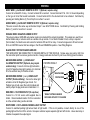
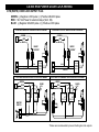
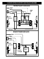
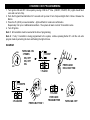
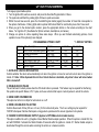
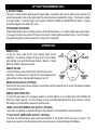
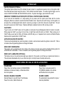
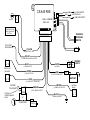
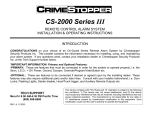
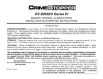
REMOTE KEYLESS ENTRY SYSTEMS
INSTALLATION & OPERATING INSTRUCTIONS
CS-845RKE / CS-855RKE
INTRODUCTION
CONGRATULATIONS on your choice of a Remote Keyless Entry System by Crimestopper Security Products
Inc. This booklet contains the information necessary for installing, and using your system. If any questions
arise, contact your installation dealer or Crimestopper Security Products Inc. at the Tech Support number
below.
*IMPORTANT INFORMATION: Primary and Optional Features
-PRIMARY: These are features that must be connected in order for the system to operate properly i.e. Power,
Ground, Lights, Power Locks, etc.
-OPTIONAL: Optional features are connected only if desired or agreed upon by the installing dealer i.e. Horn
Honk, Dome light illumination, Starter Kill, L.E.D., Trunk Pop, etc. These features may require additional parts
and labor charges. Consult with your installer about these features before installation.
TECH SUPPORT
Mon-Fri 8:00 AM-4:30 PM Pacific Time
(800) 998-6880
www.crimestopper.com
[email protected]
REV. B 5.01
This device complies with FCC Rules part 15. Operation is subject to the
following two conditions: 1) This device may not cause interference, and (2)
this device must accept any interference that may be received, including
interference that may cause undesired operation. The manufacturer is not
responsible for any radio or TV interference caused by unauthorized
modification to this equipment. Such modification could void the user's
authority to operate the equipment.
INSTALLATION CAUTIONS & WARNINGS
BEFORE BEGINNING, check all vehicle manufacturer cautions and warnings regarding electrical service (AIR
BAGS, ABS BRAKES, AND BATTERY).
DO NOT ROUTE ANY WIRING THAT MAY BECOME ENTANGLED with brake, and gas pedals, steering
column, or any other moving parts in the vehicle.
REMOVE MAIN SYSTEM FUSE(S) before jump starting the vehicle or charging the battery at high boost.
DAMAGE MAY OCCUR TO SYSTEM IF PROPER PRECAUTIONS ARE NOT OBSERVED.
COMPONENT MOUNTING
CONTROL MODULE: Locate the module underdash as high as possible. Driver’s Side usually provides an
easy location for the majority of the wiring connections. Keep the module away from moving parts such as
brake/gas/clutch pedals, or the steering column. The Placement of the module will affect the distance from
which the remote transmitter can control the unit. The antenna wire should be routed away from any metal if
possible. DO NOT alter the length of the antenna wire, route it with other wires, or ground the antenna wire.
OVERRIDE / PROGRAM BUTTON: Mount the button in a hidden but accessible location. It is used for
emergency-disarm (when optional starter disable is installed) without the use of the transmitter and for
programming certain features.
LED: The red LED provides a useful theft deterrent and serves as the indicator when changing
programming options. Choose a visible location in the dash where running the wire down through the dash
will not create any problems. Always check behind surfaces before drilling any holes!
WIRING
YELLOW WIRE: IGNITION SWITCHED “ON” AND “START” +12 VOLTS
Connect to an ignition wire (or fuse in the fuse box) that shows +12 Volts when the key in both “On” and “Start”
positions.
VIOLET WIRE: (-) PASSENGER(S) DOOR UNLOCK OUTPUT (Optional, requires relay)
Connects to unlock circuit for passenger door(s) when using separate driver’s door unlock option. See DOOR LOCK
WIRING for configuration options.
BLUE WIRE: (-) HORN HONK/CHIRP OUTPUT (Optional, requires relay)
Connects to terminal 85 of a relay. Connect terminal 86 to +12V Constant. Connect terminal 87 to +12V or GROUND
depending on the type of horn activation circuit in the vehicle. Connect terminal 30 to the horn activation circuit.
WIRING
GRAY WIRE: (-) AUXILIARY REMOTE OUTPUT 1 (Optional, requires relay)
Connect to terminal 85 of relay. Connect terminal 86 to constant. Connect terminal 87 to +12V or Ground depending
on the type of circuit that needs to activated. Connect terminal 30 to the device/circuit to be activated. Controlled by
pressing and holding Button (3) Trunk Pop for more than 1 second.
GREEN WIRE: (-) AUXILIARY REMOTE OUTPUT 2 (Optional, requires relay)
This wire connects the same way as Remote Output 1 see GRAY WIRE above. Controlled by Pressing and Holding
Button (1) Lock for more than 1 second.
ORANGE WIRE: NEGATIVE ARMED OUTPUT
This wire provides a GROUND output when system is locked with the remote transmitter. This output can used for an
starter disable relay or a device such as a window roll-up module. For a Starter Disable Circuit, a relay is required.
(Not included) Cut starter wire and connect to terminals 87A and 30 on relay. Connect orange wire to 85 and connect
86 to an IGNITION source that has voltage in the ON and CRANKING position. See Wiring Diagram.
BLACK WIRE: SYSTEM CHASSIS GROUND
THIS WIRE MUST BE CONNECTED TO CHASSIS METAL OF THE VEHICLE. Scrape away any paint or dirt from
the connection point to ensure a good connection. Keep ground wire short and try not to use factory ground locations.
BROWN WIRE 845RKE: (-) DOME LIGHT
ILLUMINATION OUTPUT (Optional, may require
external relay): Connects to Dome light activation
circuit for Negative dome light systems or to terminal
85 of an external relay for Positive circuits.
BROWN WIRE 855RKE: (+ or -) DOME LIGHT
OUTPUT (On-Board Relay): Connect to dome light
activation circuit for Negative type circuits. For
Positive type circuits, open the control module and
switch jumper the plug as shown in illustration >>>.
RED WIRE: +12V POWER INPUT (15 amp fuse)
Connect to +12 Volt source with supplied fuse &
holder. Recommended location for this connection
is at the vehicle battery positive terminal.
CS855RKE MODULE
SIDE VIEW
*NEGATIVE DOME
JUMPER
PLUG
POSITIVE DOME
JUMPER
PINS
*DEFAULT SETTING IS NEGATIVE
NOTE: DOES NOT APPLY TO CS-845RKE
WHITE WIRE: +12V FLASHING PARKING LIGHT OUTPUT
Connect to switched parking light wire at back of light switch. If this is not possible, connect directly to one of the
parking lights at the front of the vehicle. European vehicles require separate right and left circuits. Use a dual relay or
2 diodes to separate the output signal.
CS-845 RKE POWER DOOR LOCK WIRING
3 PIN (WHITE): DOOR LOCK OUTPUT PLUG
GREEN: (-) Negative LOCK pulse
RED: +12V Coil Power for external relays (Term. 86).
BLUE: (-) Negative UNLOCK pulse
CS-845RKE NEGATIVE TRIGGER DOORLOCK WIRING
CS-845RKE POSITIVE TRIGGER DOORLOCK WIRING
GREEN
GREEN
RED
RED
BLUE
BLUE
FUSED
+12V
+
85
86
87
87A 30
FACTORY
POWER
LOCKING
RELAYS
L
UL
CS-845RKE REV. POLARITY DOOR LOCK WIRING
85
86
87
87A 30
FACTORY
POWER
LOCKING
L
UL
RELAYS
CS-845RKE AFTERMARKET DOOR LOCK WIRING
GREEN
GREEN
FUSED
+12V
+
RED
BLUE
85
86
87
87A 30
85
86
87
87A 30
FUSED
+12V
+
RED
BLUE
85
86
87
87A 30
85
86
87
87A 30
MASTER
SWITCH
+
L
UL
CUT
LOCK WIRE
CUT
UNLOCK WIRE
CS-855 RKE POWER DOOR LOCK WIRING
3 PIN (WHITE): DOOR LOCK OUTPUT PLUG
GREEN: (-) Negative LOCK pulse / (+) Positive UNLOCK pulse
RED: +12V Coil Power for external relays (Term. 86).
BLUE: (-) Negative UNLOCK pulse / (+) Positive LOCK pulse
CS-855 RKE NEGATIVE TRIGGER DOORLOCK WIRING
CS-855 RKE POSITIVE TRIGGER DOORLOCK WIRING
GREEN
GREEN
RED
BLUE
RED
BLUE
L
IN4001
IN4001
DIODES *
DIODES *
FACTORY
POWER
LOCKING
RELAYS
LOCK
UL
UNLOCK
CS-855 RKE REVERSE POLARITY DOOR LOCK WIRING
L
FACTORY
POWER
LOCKING
RELAYS
LOCK
UL
UNLOCK
CS-855 RKE AFTERMARKET MOTOR/DOOR LOCK WIRING
GREEN
GREEN
RED
FUSED
+12V
+
BLUE
85
86
87
87A 30
85
86
87
87A 30
FUSED
+12V
+
RED
BLUE
85
86
87
87A 30
85
86
87
87A 30
MASTER
SWITCH
+
L
UL
CUT
CUT
*Diodes are recommended to prevent shorting door lock outputs.
CS-845/855 SEPARATE DRIVER’S DOOR UNLOCK DIAGRAMS
REVERSE POLARITY DOOR LOCKS
VIOLET
GREEN
RED
BLUE
DRIVER'S
DOOR MOTOR
FUSED
+12V
+
86
87
30 87A
85
86
87
87A 30
85
+
L
86
87
87A 30
L
CUT
UL
UNLOCK WIRE
85
CUT
+
UL
CUT
NEGATIVE TRIGGER DOOR LOCKS
VIOLET
GREEN
RED
BLUE
DRIVER'S
DOOR MOTOR
85
86
87
30 87A
L
L
UL
UL
+12V
+ FUSED
UNLOCK WIRE
CUT
FACTORY LOCK
RELAYS
TRANSMITTER PROGRAMMING
1. Turn Ignition ON and OFF 3 times quickly, leaving it ON the 3rd time. (ON/OFF, ON/OFF, ON) Lights should flash
once and one horn chirp.
2. Push the Program/Override Button for 5 seconds until you hear 3 horn chirps and lights flash 3 times. Release the
Button.
3. Press the #1 (LOCK) on new transmitter – lights will flash for code learn confirmation.
Repeat step 3 for up to 2 additional transmitters. The system will learn a total of 3 transmitter codes.
4. Turn off Ignition.
Note 1: All transmitters must be learned at the time of programming.
Note 2: If only 1 transmitter is being programmed to the system, continue pressing Button #1 until the unit exits
program mode by unlocking the door and flashing the lights 2 times.
DIAGRAM:
IGN
OFF
TURN IGN. ON
3 TIMES:
ON, OFF
ON, OFF
ON.
1 CHIRP
PRESS AND
HOLD BUTTON
1 FLASH
IGN
3 CHIRPS
PAN IC
3 FLASHES
PRESS BUTTON 1
1 FLASH
FOR EACH
TRANSMITTER
OFF
TURN IGN. OFF
OPTION PROGRAMMING
To change programmable options:
1. Turn the Ignition ON, wait one second, and press the Override/Program button 5 times.
2. The system should flash the parking lights 8 times in quick succession.
3. Within the next few seconds, press the Override/Program button [again] the number of times that corresponds to
the options chart below. Parking lights and/or optional LED should flash for each button press. Don’t lose count!
4. When you get to the desired option number, press the appropriate button on the remote according to the chart
below. Turn Ignition off. (See Below for Option numbers, descriptions, and values.)
5. Change one option at a time repeating these same steps. When you are finished customizing options, check
operation to see if the option(s) have changed.
PROGRAMMING OPTIONS CHART
Option #
1.
2.
3.
4.
5.
6.
Option Description
Auto Lock & Unlock with Ignition
Double Unlock Pulse
Horn Chirp
Lock/Unlock Pulse Time
Passive Starter Disable
Ignition Trigger
Selection
ON or OFF
ON or OFF
ON or OFF
0.8 Sec. or 3 Sec.
ON or OFF
ON or OFF
* = DEFAULT SETTING
Lock Button
ON*
OFF*
ON*
0.8 Sec.*
OFF*
OFF*
Unlock Button
OFF
ON
OFF
3 Sec.
ON
ON
1. AUTOLOCK / UNLOCK WITH IGNITION
Controls whether the doors will automatically lock when the ignition is turned on and will unlock when the ignition is
turned off. Note: When Separate Driver’s Door Unlock feature is installed, only driver’s door will unlock when
IGN. is turned off.
2. DOUBLE UNLOCK PULSE
The unit will send 2 unlock pulses when the #2 Unlock button is pressed. This feature may be required for interfacing
this system into specific Nissan, VW, Toyota, and Lexus vehicles that require 2 unlock pulses to unlock the vehicle.
3. HORN CHIRP CONFIRMATION
This option turns the horn chirps for lock/unlock on or off.
4. DOOR LOCK/UNLOCK PULSE TIME
Controls the amount of time (0.8 sec. or 3 sec.) for the lock/unlock pulse. The 3 sec. setting may be required for
1980’/90’s European Vehicles that require a long pulse to operate electric vacuum type door lock systems.
5. PASSIVE STARTER DISABLE OUTPUT (Applies to OPTIONAL starter disable feature)
This option modifies the unit’s (-) Negative Armed Starter Disable output operation. When this option is turned ON, the
unit will PASSIVELY activate the Starter Disable 45 seconds after the ignition is turned off. Starter disable output is
deactivated through the remote when unlocking the vehicle or a manual override.
OPTION PROGRAMMING cont.
6. IGNITION TRIGGER
This option controls the unit’s optional Ignition trigger feature. If selected to ON, then the vehicle’s horn will honk if an
unauthorized operator turns on the Ignition after the vehicle had been locked with the remote. This function is similar
to an alarm system. To avoid a trigger, use the remote for BOTH LOCKING and UNLOCKING the vehicle. If system
accidentally triggers, press button #4 to reset.
OPTION RESET PROCEDURE:
Programmable Options can be instantly restored to Factory Default Values (*): To restore default values, perform step
#1 on page 8, then just press button #3 (Trunk) on the remote. Parking lights should flash 4 times. Turn OFF Ignition.
All programming options should be restored to * values (See chart page 8).
OPERATION
REMOTE LOCK
To lock the doors, press the #1 (Lock Symbol) button on the
transmitter. You will hear a single horn chirp (if horn chirp enabled),
lights will flash once and LED will begin flashing. Optional: If starter
disable is installed, it will become active.
#2
UNLOCK
#1
LOCK
PANIC
REMOTE UNLOCK
To unlock the doors, press the #2 (Unlock Symbol) button on the
transmitter. You will hear 2 horn chirps (if horn chirp enabled) and the
lights will flash 2 times. Optional starter disable will turn off.
#3
TRUNK
POP
#4
REMOTE
PANIC
DRIVER’S DOOR UNLOCK (OPTIONAL)
Press the #2 Unlock button (Unlock Symbol) a second time to unlock remaining door or doors if this feature is installed
on your particular vehicle.
REMOTE PANIC PROTECTION
To sound the panic alarm in an emergency situation or to draw attention to your vehicle press and hold Button #4
(Panic) for at least 2 seconds. The horn will begin to pulse and parking lights will flash for up 45 seconds or until the
Panic Button on the transmitter is pressed to reset this mode.
TRUNK / HATCH POP (REMOTE AUX. OUTPUT 1, OPTIONAL)
To pop the trunk (Optional), press Button #3 (Open Trunk Symbol) on the transmitter for at least 2 seconds.
2nd AUX. OUTPUT (REMOTE AUX. OUTPUT 2, OPTIONAL)
To activate the Second auxiliary output press and hold Button #1 (Lock) and hold for more than (1) second. This
output can be used to control other optional add-on accessories such as a Remote Engine Start Module.
OPERATION
IGNITION TRIGGER (OPTIONAL)
This optional feature allows the unit to activate the panic mode if an unauthorized operator turns on the Ignition after
the vehicle had been locked using the remote. This is similar to an alarm feature. To avoid an Ignition trigger, use the
remote for BOTH LOCKING and UNLOCKING the vehicle. If system does trigger, press button #4 to reset.
EMERGENCY OVERRIDE/VALET MODE (WITH OPTIONAL STARTER DISABLE FEATURE)
If you have lost the transmitter or it stops working for any reason and the system was locked with the remote
Emergency Disarm is needed to override the Starter Disable circuit. Open the door with the key, turn the ignition on
and press the override/program button about 2 seconds you will get (1) short horn chirp and (1) light flash. This will
also put the system into VALET mode. If Optional LED light is installed, it will turn ON and stay on solid.
VALET MODE
To get in and out of VALET mode, turn the ignition on and press the override/program button for about 2 seconds.
When going into VALET you will get (1) horn chirp, (1) light flash, and LED will be on SOLID. When coming out of
VALET mode you will get (2) Chirps, (2) Flashes, and LED will go out. Separate driver’s unlock and Starter Disable
features will not operate when in VALET mode.
AUTOLOCK/UNLOCK WITH IGNITION
The doors will automatically lock when the ignition is turned on and will unlock when the ignition is turned off. If this is
not desired, See Programming Options to change this feature.
HORN CHIRP CONFIRMATION
This system can be programmed for short chirps of the Factory Car Horn along with the Flashing Parking lights for
LOCK/UNLOCK confirmation. If this is not desired, See Programming Options to change this feature.
DOME LIGHT ILLUMINATION (OPTIONAL)
This feature turns on the vehicles dome light upon disarm for 30 seconds or until the key is inserted and turned on.
This will provide illuminated entry to your vehicle at night or in dimly lit areas for safety and security.
ADDITIONAL INSTALLATION ACCESSORIES
CS-6600 DLM
CS-6500 DLI
Plug-in Door lock interface module for CS845/855RKE
installation into Reverse Polarity or Aftermarket Motor
door lock systems.
Plug-in Door Lock pulse inverter for
CS-845RKE installation into vehicles
with Positive Door lock systems.
XX-402A / XX-402B / XX-402PB
XX-SRS / XX-DRS
External Relays for use with Power Trunk Release
Power Door Locks, Starter Disable etc.
Pre-wired plastic relay sockets for single or
dual relay installation
CS-845 RKE
IGN. SW
FUSE
BOX
(-) LOCK OUTPUT
GREEN
RED
+12V FOR RELAYS
(-) UNLOCK OUTPUT
BLUE
BLUE: OVERRIDE
RED: LED
ACTIVATES ON 2nd
PRESS OF UNLOCK
BUTTON
OVERRIDE/
PROGRAM
SWITCH
TO FACTORY
HORN RELAY
LED
YELLOW
+IGN SW ITCHED "ON"
VIOLET
(-) PASSENGER UNLOCK OUTPUT
86
85
87
87A 30
BLUE
WHITE
(-) HORN OUTPUT
RELAYS NOT
INCLUDED
+ 10A MAX
GREEN
(-)AUX OUTPUT #2
86
85
87
87A 30
PARKING
LIGHTS
RED
+12 VOLT POWER INPUT
FUSE
15 A
GRAY
+
BATTERY
(-) AUX OUTPUT (TRUNK POP)
IGNITION
+
"ON & START"
OPTIONAL
STARTER DISABLE
RELAY
BROWN
86 85
ORANGE
(-) DOME LIGHT OUTPUT
(-) NEG. ARMED OUTPUT
85
30 87A
BLACK
CHASSIS GROUND
CUT
START WIRE
STARTER
OPTIONAL
RELAY
86
87
87A 30