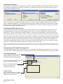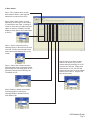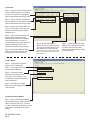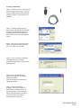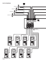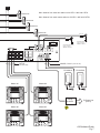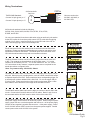
1
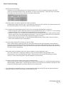
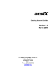
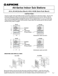
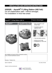
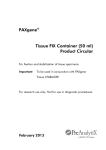
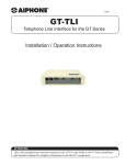
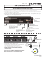
#96501
1010
AX QuikStart Guide
- INITIAL INSTALLATION INSTRUCTIONS Before proceeding with the installation of the AX system, please review these instructions.
1. The complete AX System Installation & Operation Manual is located on the CD included with the CEU.
2. The software program to set up the CEU is located on the CD as well. The CEU must be configured specifically for
your system in order for it to function properly.
3. Included with the CEU is a USB to serial converter, along with a gender changer. This is supplied to allow any PC
with a USB port to be used to program the AX CEU.
On/Off power switch
RS232 port
Used for programming
Door Station Ports
RJ-45 jacks
Master Station Ports
RJ-45 jacks
Door Release Contacts
Each contact can be programmed
to be either N/O or N/C. Contact
rating 500mA. Use the RY-24L for
higher current devices.
Open collector outputs for
video signal trigger (top)
AX-320 Add-on CEU ports (bottom)
RJ-45 jacks
Two 24V DC inputs
Parallel inputs on one PS-2420UL
for audio-only systems
Telephone Output
Connects to Viking Model K-1900-5 Dialer
Video Outputs.
Each talk path has its own output.
When connecting to a DVR, two
channels must be used.
3-7/16”
AX-248C
Connecting Central Exchange Unit to Computer via USB-to-Serial Converter:
RS232C Port
16-7/8”
1. Connect power supplies and turn
on CEU.(13-3/16” Depth) DB9 F/F
2. If a serial output is not available on your PC, install the USB
Gender Changer
driver that comes with the converter on your PC.
USB-to-Serial
3. Attach the gender changer to the converter and plug
Converter
converter into the RS232 port on the AX Exchange unit.
4. Plug the other side of the USB converter into the USB
port on the computer.
To USB Port
on PC
Actual components
(supplied with AX-CEU)
This will allow you to upload and download program information
between the PC and CEU via the AX Setup Tool program.
AX Quikstart Guide
Pg. 1
Installing the Software
Insert the CD or download the AX software from our website. Open the AXSetup.exe program and you will be presented
with a dialog box asking where to install the AX program. The dialog box will look like one of these depending on the
language packs installed on the PC.
Click on the button next to the dialog box [R] or [Reference...], this will bring up a window entitled “Browse for Folder”.
Select a memorable destination (i.e. Desktop) and then press [OK] to complete the Browse for Folder window, and then
[OK] on the “SFX” window to extract the AX software to that destination. To open the software, navigate to that location
and then double click the AXSetupEN.exe icon.
Installing the USB-to-Serial driver
If you are utilizing the provided USB-to-Serial cable, download the drivers from our website (http://www.aiphone.com/
products/downloads/) or insert the mini-CD supplied with the AX-CEU. Open the CD-ROM drive from My Computer
named Driver. Open the folder USB TO SERIAL CABLE V1.1, then open the folder Windows. Open the folder Install,
then open the application PL-2303 Driver Installer. Follow the messages to install and restart the computer if prompted.
Plug in the cable to the computer and determine the COM port assigned to it by clicking the Start button and right-clicking
on My Computer and select Properties from the drop down menu. When the System Properties window appears, select
the Hardware tab and click the Device Manager button. With the Device Manager open, scroll to Ports (COM & LPT).
The Aiphone supplied USB-to-Serial converter will be shown as Prolific USB-to-Serial Comm Port (COMx); the number
where the “x” is indicates the COM port number to be chosen in the AX Setup Utility.
Note: The AX Setup Utility will only recognize COM ports numbered from COM1 to COM9. If the default COM port is outside of that range, reassign
COM port numbers by right clicking the driver and choosing Properties from the drop down menu. Click Advanced and choose an unused port between
1 and 9.
Configuring the AX Central Exchange Unit:
The following describes the basics of the AX Setup Tool. Note that the CEU MUST be programmed via a PC in order for
the system to work. Without programming, only Master1 (M1) and Door 1 (D1) will operate when connected to the CEU.
1) Central Exchange Unit
Step 1: Select the COM Port you will
be using. (Based on using existing
serial port or USB port with converter.)
Step 2: Select which model CEU that you
are using via the dropdown box.
Step 3: If any AX-320C add-on
CEU’s are included, click
“Connected” for each one.
2) Master Station
Step 1: Select the number of masters
being used and whether it is a video
master or audio only master.
AX Quikstart Guide
Pg. 2
3) Door Station
Step 1: Fill in location name of each
door station if desired. (Not required.
Names are not stored in the CEU)
Step 2: Select Video, Audio, or None
depending on which type of door station
is connected to each input. (If setting remains on Video when an audio-only door
station is used, the AX-8MV’s LCD will
display a snowy picture when that station
is active.)
Step 3: Set the call priority level by
selecting Priority or Normal from the Call
Level tab. Priority level calls will have a
faster call tone and flashing LED on the
master.
Step 4: Set the door release contact to
either Normally Open or Normally Closed
by selecting N.O. (Normally Open) or N.C.
(Normally Closed) on the DR Relay tab.
The default is N.O.
Step 6: Select if you want the door
station’s call tone to ring on each
master station by selecting On or Off
from the Call Tone tab. Please note
that when set to “Off”, the LED and
monitor will still come on at the master
when the door calls in. Only the call
tone will be muted.
Step 5: Enable or disable each station
for being eligible for scanning by
selecting Enable or Disable from the
Scan Monitor Tab.
AX Quikstart Guide
Pg. 3
4) Time-Out
Step 1: Set Call-in time for door stations
from 10 to 600 seconds or to infinite if
the call is to ring until it is answered.
(Set for both Normal and Priority Calls)
Step 2: Set the duration of an All Call
announcement from 10 to 600 seconds.
(Set for both Normal and Priority Calls)
Step 3: Set the CO Transfer time from
10 to 300 seconds for how long a CO
transferred call will ring the outside
telephone line.
Step 4: Set the Communication time
for the maximum amount of time
allowed for an intercom conversation
(30 to 600 seconds). Set the CO
Communication time for the maximum
amount of time allowed for a CO
transferred call (30 to 600 seconds).
Step 5: Set the Door Release Relay
setting for the duration of time that
the contacts are to be activated.
5) CO Transfer
Step 1: If using the CO Transfer
feature, click on the Enable
button. If not, skip to section 6,
Communication Method.
Step 2: If Reverse Polarity
Detection is required for your
phone line, click on Detect. This
is sometimes required, depending
on the phone line.
Step 3: The wait time for RingBack-Tone can be adjusted from
1-60 seconds.
6) Communication Method
Step 1: The Communication Method
can be switched from “VOX or Press-toTalk” to “Press-to-Talk” only. If “Pressto- Talk” is selected, the hands-free VOX
feature will be disabled on all master
stations.
AX Quikstart Guide
Pg. 4
Step 6: Set the Door Station
Monitor for the amount of time that
you want to be able to listen in to a
door station (10 to 600 seconds).
When a door station is selected, the master
will be in listen mode for this length of time,
then will time out..
Step 7: Set the Door Station Scan
Monitor for the amount of time that
you want to listen to each door
station while in Scan Monitor mode
(5 to 60 seconds).
4) Saving / Uploading
Step 1: Connect your PC / Laptop to the
AX-CEU as shown on page 1. Use the
supplied USB-to-Serial Converter and
Gender Changer if a Serial port is not
available.
Step 2: Save the settings that you
have made by clicking on File and then
Save As. Use the name of the job or
something that describes the job as
the file name so you can refer back to
it later.
Step 3: Click on Tool, then CEU, then
Upload to upload the system settings
you have made to the AX-CEU.
Step 4: Click Yes to the confirmation
message asking if you want to
overwrite the information in the Central
Exchange Unit.
Step 5: Enter the password to
authorize the upload. The default
password is 9999.
Click OK and the new settings will
upload to the CEU.
Step 6: When the upload is
complete, remove the connector
cable from the CEU and save it in
a secure location. (This connector
will be required when any changes
are to be made to the system
programming in the future.)
AX Quikstart Guide
Pg. 5
BLOCK DIAGRAM:
PT
Release #4
Release #3
Release #2
AX-084C
Release #1
CAT-5e
16-7/8” (
(max dist. 980’)
3-15/16"
AX Quikstart
3-15/16" Guide 1"
Pg. 6
3-15/16"
3-15/16"
1"
1"
3-15/16"
3-15/16"
AX-DV
Door #8
7-11/16"
AX-DV
Door #7
7-11/16"
7-11/16"
1"
7-11/16"
AX-DV
Door #6
7-11/16"
AX-DV
Door #5
1"
AX-DV
Door #4
7-11/16"
3-15/16"
AX-DV
Door #3
7-11/16"
AX-DV
Door #2
7-11/16"
AX-DV
Door #1
1"
3-15/16"
1"
1"
PT
Max. distance from each door station to AX-CEU = 980’ with CAT5e.
Release #5
Max. distance from each master station to AX-CEU = 980’ with CAT5e.
Release #6
Release #7
Release #8
V+ to core
V+ to core
V- to braid
3-7/16”
V- to braid
Composite Video Output
(1Vp-p, 75 Ohm)
Talkpath / Channel 2
18AWG, 2 cond.
CAT-5e
(13-3/16” Depth)
(max dist. 980’)
(max dist. 16’)
PS-2420UL
Master #1
PS-2420UL
Master #4
Viking
K-1900-5
Master #2
Composite Video Output
(1Vp-p, 75 Ohm)
Talkpath / Channel 1
To Phone Line
(POTS)
Master #3
AX Quikstart Guide
Pg. 7
AX Master options via included 6-pin connector
Monitor / DVR
5’ max
Brown V+ to Coax Core
Red V- to Coax Braid
Orange
Yellow
Green
N/O Dry
Blue
Input
(foot switch)
PS-2420UL
+
-
White
Blue
Red
Black
RY-ES
Orange
Orange
To Bell/Light
& Power
1) Connect Brown (V+) and Red (V-) to coax input of standard monitor / DVR.
Maximum wire run is 5’. Output is 1Vp-p, 75 ohm.
2) Connect Orange and Yellow wires to either an IER-2 chime extension
speaker, or to the White and Blue wires on the RY-ES relay for an external
device signaling.
3) Connect the Green and Blue wires to any normally open dry contact
device, to be used in place of the talk button on the master. Contact
device should be no more than 50’ from the master.
Connecting to Strike/Maglock with RY-24L
Lock
Power
Strike
RY-24L color code:
Red = Positive Trigger
Black = Negative
Brown = Common
Orange = N.O. Contact (door strike)
Yellow = N.C. Contact (mag lock)
brn
org
Mag Lock
Lock
Power
red
brn
blk
yel
To - 24VDC
blk
red
Use Brown and Orange wires
when connecting to electric
strike.
AX-084C
3-7/16”
To + 24VDC
Use Brown and Yellow wires
when connecting to maglock.
3-15/16"
16-7/8” (13-3/16” Depth)
7-11/16"
AX-DV
7-11/16"
AX-DV
1"
AX Quikstart Guide
Pg. 8
3-15/16"
1"
Wiring Terminations:
CAT5e
AX-Series Audio
Only Sub
TIA/EIA 568B Standard:
Connect 3/6 pair (green) to “1”
Connect 7/8 pair (brown) to “2”
1
2
3
4
5
6
7
8
1
2
Orange/White
Orange
Green/White
Blue
Blue/White
Green
Brown/White
Brown
Homerun each sub to
AX-084C, AX-248C, or
AX-320C CEU
AX-Series sub stations include the following:
AX-DM, AX-A, AX-AN, AX-B, AX-BN, IF-DA, IE-DC, IE-JA, IE-SS,
IE-SSR, and IE-SSV.
You can use a standard 2-conductor cable when using an audio-only sub station.
At the CEU, splice the 2-conductor cable onto a CAT-5e cable with the splicing
method of your choice. Install an RJ-45 plug on the CEU end of the CAT-5e
cable, then simply plug it into the AX Exchange Unit.
AX-248C
RJ-45 connectors for the door station ports are located on the left side of the
exchange. Please note that the odd numbers are located on top and the even
numbers are located on the bottom. The master ports are in the center of the
CEU with the odd numbers on top and even numbers on bottom.
AX-248C
16-7
The Door Release Contacts can be individually programmed to be either N/O
or N/C. The contacts are located above the door station ports. “L1” are the
contacts* for door station port “D1”, “L2” are the contacts for “D2”, etc. As the
“L#” connections are dry contacts, a separate power source is required for the
actual door strikes or magnetic locks.
*Note: Dry contact rating: 24V AC/DC, 500mA.
AX-248C
16-7
3-7/16”
The AX-084C and AX-248C units have a built-in composite video output, one per
talk path. When tying to a recording device, such as a DVR, connect each output
to separate inputs on the DVR. Each output also has a corresponding trigger, via
a normally open collector labeled VCH1 and VCH2. Pin 4 is the trigger and pin
5 is the ground. Please note that the video signal is only present when a video
door station is active and there is an image on the AX-8MV’s monitor.
AX-248C
3-7/16”
16-7/8” (13-3/16” Depth)
Depth)
-24VDC
+24VDC
16-7/8” (13-3/16” Depth)
3-7/16”
AX-248C
The AX-084C and AX-248C are powered by two PS-2420UL
power supplies.
16-7/8”
(13-3/16”
One power supply can be used for an audio-only system. When using one power
supply, jumper the two + terminals together and connect to + of the power supply.
Jumper the two negative’s together and connect to - of the power supply. Power
(13-3/16”
Depth)
for the AX-320C add-on CEU’s comes from the system16-7/8”
power supplies.
Parallel
connect power wires to all AX-320’s in the system.
3-7/16”
The AX-084C and AX-248C both have the ability to connect to the AX-320C addon unit. Connect the X1 and X2AX-248C
with two CAT-5e cables. Both X1 and X2 must
be connected and the AX-320C must be within 16 feet of the main CEU.
AX Quikstart Guide
Pg. 9
AX Series CAT5e wire Installation Do’s and Don’ts
Do
Run all cables in a “Star” configuration. That is to say that they all emanate from and are “homerun” to,
one central location, where the AX-CEU will be installed. Visualize a wagon wheel. All of the spokes
start from one central point.
Do
Keep all cable runs to a maximum of 980 feet (for each run). IMPORTANT! This is an AX Series
specific distance.
Do
Maintain the twists of the pairs all the way to the point of termination, or no more than 1/2” untwisted.
Do Not
Do
Do Not
Do
Do Not
Do
Do Not
Do
Do Not
Do
Skin off more than 1” of jacket when terminating.
Make gradual bends of the cable where necessary. No sharper than a 1” radius.
Allow the cable to be sharply bent or kinked at any time. This can cause permanent damage to the
cables’ interior.
Dress the cables neatly with cable ties. Use low to moderate pressure.
Over tighten cable ties. Hook or Loop (Velcro) Cable Ties work very well for commercial installations.
Cross-connect cables (where necessary) using CAT5e rated punch blocks and components.
Splice or bridge CAT5e cable at any point. There should never be multiple appearances of CAT5e
cable.
Use low to moderate force when pulling cable.
Use excessive force when pulling cable.
Use cable pulling lubricant for cable runs that may otherwise require great force to install.
Do Not
Use oil or any other lubricant not specifically designed for cable pulling. Oil or other lubricants, can
infiltrate the cable, causing damage to the installation.
Do
Keep CAT5e cables as far away from potential sources of EMI (electrical cables, transformers, light
fixtures, etc.) as possible.
Do Not
Do
Do Not
Tie cables to electrical conduits or lay cables on electrical fixures.
Install proper cable supports, spaced no more than 5 feet apart.
Install cable that is supported by the ceiling tiles (this is unsafe and may be a violation of building
codes).
Do
Always label every termination point. Use a unique number for each cable segment.
Do
Always test every installed segment with a cable tester. “Toning” alone is not an acceptable test.
Do
Always install jacks in such a way as to prevent dust and other contaminants from settling on the
contacts. The contacts (pins) of the jack should face up on flush mount plates or left, right. or down
(never up) on surface mount boxes.
Do
Always leave extra slack on the cables, neatly coiled up in the ceiling or nearest concealed place. it is
recommended that you leave at least 5 feet at the door station side and 10 feet at the CEU side.
Do Not
Install cables “taught” in the ceiling or elsewhere. A good installation should have the cables loose but
never sagging.
Do
Always use grommets to protect the cable where passing through metal studs or anything that can
possibly cause damage to them.
Do
Configure the RJ45 jacks in the 568B wiring standard. 568B standard is required for the AX system.
Do Not
Do Not
(1 Exception)
Do
Use the 568A wiring standard for the AX system.
Use staples on CAT5e cable that crimp the cable tightly. The common T-18 and T-25 cable staples are
not recommended for CAT5e cable. The T-59 insulated staple gun is ideal for fastening CAT5e cabling
as it does not put any excess pressure on the cable.
Always obey all local and national fire and building codes. Be sure to “firestop” all cables that
penetrate a firewall. Use plenum rated cable where it is mandated.
AX Quikstart Guide
Pg. 10
Basic Troubleshooting:
•
AX-CEU Power LED flashing:
Possible incorrect program setting for the Central Exchange Unit. If there is no add-on exchange (AX-320C),
make sure the program setting for No. 2 through No. 4 is set to “Not Connected”. If these are set to “Connected”
but no add-on is connected to the main CEU, the power LED will flash.
•
Audio-only system, door station squeals when station is selected:
Possible power supply connection issue. In an audio-only system with one PS-2420UL, the power terminals must
be commoned together on the AX-CEU. Refer to the bottom of Page 9.
•
Error message while downloading program to CEU “Error occured while downloading the setting file”:
1. Power not applied to CEU: Make sure that there is power applied to both the V+ V- and D+ D- on the exchange
and that the power LED is on bright when the power switch is in the ON position.
2. System is currently in use: If there is any current activity on the exchange, such as a master monitoring a door,
then the system will not accept programming information. To ensure no activity, unplug the RJ-45 connections
from the CEU and only leave power and the programming cable connected.
3. Check the serial cable being used. If using the provided USB-to-Serial converter cable, make sure that the
drivers were installed on your PC (see page 2).
•
One of the master station LED’s is blinking on the AX master:
When a master station is programmed to be in the system and that station gets unplugged or disconnected in
some way, the corresponding master LED will blink quickly on the other master station(s) that are still connected
indicating that there is a problem. Check the wiring to the master station assigned to the channel with the blinking
LED and reconnect appropriately.
•
Video master station still displays video even when a substation is not programmed to call it:
This is not a malfunction. Assigning a substation to only call certain masters simply eliminates it from
annunciating (no call tone) at that particular master. Other functions, such as the LED blinking, the monitor
coming on, or the master being able to call that substation are still functional.
•
AX master not able to hear the door station (stuck in Transmit mode):
Check to see if the 6-pin connector is plugged into the back of the AX master unit. If the blue and green wires are
shorted together, separate them. The blue and green wires are for connection of a footswitch to activate the TALK
function and if shorted together, the master will be stuck in transmit mode.
•
If you are having communication issues, it is recommended to bench test the AX-CEU with the masters and doors
using patch cables to insure that the product is functioning normally.
AX Quikstart Guide
Pg. 11
Labeling the Master Station’s Directory Cards
Aiphone provides a template for creating professionally printed directory cards for the AX series master stations.
The template is located on the CD included with
the CEU.
View the CD contents using My Computer or
Windows Explorer.
Example: Directory cards when using template
Master Stations
Door Stations
- Open the file folder called “Directory Card”
- Open PDF document “AX-8MV_DirectoryLetter”
- Type in the location names of master stations
and door stations.
- Print and cut the strips to fit in the directory slots
on the master stations.
- Remove the plastic directory cover and replace
the blank paper strips that are included with the
master with the new labeled strips you’ve just
made.
- Replace plastic directory cover.
FRONT
OFFICE
FRONT
DOOR
S&H
OFFICE
EMPL.
ENTRANCE
EMPL.
LOUNGE
DELIVERY
DOOR
SECURITY
DESK
ELEVATOR
LOBBY
SPECIFICATIONS:
AX-084C, AX-248C
Power Source:
Current Consumption:
Door Release Contact:
Mounting:
Wiring:
Operating Temperature:
24V DC, 2A (x2), PS-2420UL (1 for audio-only system, 2 for audio/video system)
Video (Max) 1.1A, Audio (Max) 1.25A
24V AC/DC, 500mA
Desk, wall, or 19” EIA rack with supplied brackets
RJ45 plugs for CAT5e from masters and doors.
2 Conductor wire from PS-2420UL to power input terminals
RJ11 for Viking K-1900-5 programmable auto-dialer
32 - 104° F (0 ~ 40° C)
AX-8MV, AX-8M
Power Source:
Call Tone:
Communication:
Video Monitor (AX-8MV):
Scanning Lines (AX-8MV):
Video Output (AX-8MV):
Headset Jack:
Mounting:
Wiring:
Operating Temperature:
24V DC Supplied from CEU
Tremolo ring tone & blinking LED
Open voice hands-free (VOX or Push-to-Talk)
3-1/2” direct view TFT color LCD
525 lines
NTSC Standard 1Vpp (0.7 - 1.4Vpp)
3.5mm mic and speaker jacks
Desk with flip-up stands, or wall mount with provided metal bracket
RJ45 Plug, CAT5e homerun to CEU
32 - 104° F (0 ~ 40° C)
AX-DV, AX-DVF
Power Source:
Communication:
Camera:
Pixels: Minimum Illumination:
Mounting:
Wiring:
Operating Temperature:
24V DC Supplied from CEU
Hands-free
1/4” Color CCD camera
250,000 Pixels
5 Lux
AX-DV: Surface wall mount
AX-DVF: Flush mount (with provided box)
RJ45 Plug, CAT5e homerun to CEU
14 - 140° F (-10 ~ 60° C)
Aiphone Communcation Systems
1700 130th AVE N.E.
Bellevue, WA 98005
(425) 455-0510
FAX (425) 455-0071
Toll Free Technical Support:
1-800-692-0200
E-mail [email protected]
AX Quikstart Guide
Pg. 12
Stock # 96501
1010JDPH