1
GE Consumer & Industrial
Technical Service Guide
June 2009
Monogram
Professional Range
and Rangetops
ZDP486ND
ZDP486NR
ZDP484NG
ZDP364ND
ZDP364NR
ZDP366N
ZDP304N
ZGU366N
ZGU364ND
ZGU364NR
ZGU486ND
ZGU484NG
ZGU486NR
31-9181
GE Appliances
General Electric Company
Louisville, Kentucky 40225
IMPORTANT SAFETY NOTICE
The information in this service guide is intended for use by individuals possessing
adequate backgrounds of electrical, electronic, and mechanical experience. Any
attempt to repair a major appliance may result in personal injury and property
damage. The manufacturer or seller cannot be responsible for the interpretation
of this information, nor can it assume any liability in connection with its use.
WARNING
If the information in this manual is not followed exactly, fire or explosion may
result causing property damage, personal injury or death. If you smell gas:
–
Do not try to light any appliance.
–
Do not touch any electrical switch; do not use any phone in the
building.
–
Immediately call the gas supplier from a neighbor’s phone. Follow the
gas supplier’s instructions.
–
If you cannot reach the gas supplier, call the fire department.
WARNING
To avoid personal injury, disconnect power before servicing this product. If
electrical power is required for diagnosis or test purposes, disconnect the power
immediately after performing the necessary checks.
RECONNECT ALL GROUNDING DEVICES
If grounding wires, screws, straps, clips, nuts, or washers used to complete a
path to ground are removed for service, they must be returned to their original
position and properly fastened.
GE Consumer & Industrial
Technical Service Guide
Copyright © 2009
All rights reserved. This service guide may not be reproduced in whole or in part in any
form without written permission from the General Electric Company.
–2–
Table of Contents
Back Panel............................................................................................................................................................................47
Bake Element ......................................................................................................................................................................61
Broil Elements .....................................................................................................................................................................56
Component Locator Views ...........................................................................................................................................27
Control Board Connector Locator .............................................................................................................................68
Control Features - Range ..............................................................................................................................................11
Control Features - Rangetop ....................................................................................................................................... 8
Control Panel .....................................................................................................................................................................30
Convection Bake Element .............................................................................................................................................57
Convection Fan Assembly ............................................................................................................................................58
Cooling Fan ..........................................................................................................................................................................48
Diagnostics and Service Information ......................................................................................................................71
Door Assembly ...................................................................................................................................................................51
Electronic Oven Control .................................................................................................................................................67
Factory Test Mode ..........................................................................................................................................................71
Gas Conversion Range and Rangetop....................................................................................................................22
Glow-bar Igniter ...............................................................................................................................................................39
Griddle Assembly .............................................................................................................................................................35
Griddle Burner Igniter .....................................................................................................................................................37
Griddle Control ..................................................................................................................................................................37
Griddle Safety Valve ........................................................................................................................................................37
Grill and Griddle Ignition Systems ..........................................................................................................................38
Grill Assembly ....................................................................................................................................................................31
Grill Burner Igniter ............................................................................................................................................................33
Grill Control .........................................................................................................................................................................34
Grill Safety Valve ...............................................................................................................................................................33
Indicator Light Assembly .............................................................................................................................................46
Installation ..........................................................................................................................................................................19
Introduction ......................................................................................................................................................................... 5
LED Lights and Power Supply ....................................................................................................................................45
Lock Assembly ...................................................................................................................................................................49
–3–
Meat Probe Receptacle and Harness ......................................................................................................................63
Nomenclature - Range ................................................................................................................................................... 6
Nomenclature - Rangetop............................................................................................................................................ 7
Optional Accessories .......................................................................................................................................................84
Oven Component Circuits .............................................................................................................................................81
Oven Components ...........................................................................................................................................................51
Oven Control Logic Board ..........................................................................................................................................60
Oven Light Assemblies ...................................................................................................................................................65
Oven Operational Notes ................................................................................................................................................25
Oven Racks ..........................................................................................................................................................................54
Oven Relay Board ..........................................................................................................................................................60
Oven Sensor, Sail, and Door Switch Test ................................................................................................................76
Oven TCO ..............................................................................................................................................................................49
Oven Temperature Sensor............................................................................................................................................56
Range Components .........................................................................................................................................................47
Sail Switch ............................................................................................................................................................................49
Schematics and Wiring Diagrams ............................................................................................................................77
Side Access Panel .............................................................................................................................................................47
Spark Module .....................................................................................................................................................................43
Surface Burner ..................................................................................................................................................................41
Surface Burner Base .......................................................................................................................................................39
Surface Burner Igniter ....................................................................................................................................................40
Surface Burner Pan ........................................................................................................................................................40
Surface Burner Valve and Switch ............................................................................................................................42
Surface Component Circuits .......................................................................................................................................79
Surface Components ......................................................................................................................................................30
Task Light Switch ..............................................................................................................................................................46
Transformer .......................................................................................................................................................................44
Warranty-Range ...............................................................................................................................................................86
Warranty-Rangetop ........................................................................................................................................................85
–4–
Introduction
*Monogram introduces the new GE Monogram Professional Range and Rangetops. Their superior style
and performance parallel commercial units. Available in 48-, 36-, and 30-inch Ranges and 48- and 36-inch
Rangetop models -- these units feature electronic dial controls that combine the precision of modern digital
technology with the simplicity of traditional mechanical controls.
•
Authentic Professional appearance using premium-grade, 304 stainless steel with smoothly finished
edges, large electronic control knobs, and heavy duty handles.
•
Sealed, dual-flame stacked burners deliver a full spectrum of heat settings, from an ultra-low 140°F
simmer to an intense 18,000 BTUs.
•
Electronic ignition with automatic
reignition ensures a continuous
flame which reignites automatically if
accidentally extinguished.
•
Reversible burner grates are flat on one
side and uniquely contoured on the other
to accommodate round-bottom woks.
•
Stainless steel and aluminum-clad griddle
offers 18,000 BTUs of cooking power,
allowing fast and consistent heating
across the entire cooking surface.
•
Grill with infrared ceramic burner can
be adjusted from 14,000 BTUs down to
approximately 10,000 BTUs.
•
Monogram Professional oven system
combines European, reverse-air convection
technology and six heating elements in each
oven to provide superb baking results.
•
Main ("Caterer's") oven is uniquely sized to
accommodate three full-sized sheet trays.
•
Companion ("Everyday") oven is just the right size for 9" x 13" casserole dishes.
•
Halogen light columns provide a clear view, regardless of rack position.
•
Heavy-duty, full-extension racks glide smoothly in and out on stainless steel ball bearings for easy
access, and are designed to remain in the oven during the self-clean cycle.
•
LED task lights below the bullnose provide a functional and theatrical touch.
•
Optional Fixed- (12 inch ) or adjustable-height (30 to 36-inch) backsplashes with shelf are available.
•
Optional black knob kit available.
*Features may vary by model.
–5–
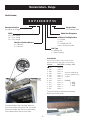
Nomenclature - Range
Model Number
Z D P 486 N D P SS
Monogram Product
Monogram Pro Range
Product Color
SS = Stainless Steel
Width
48 = 48-in. Range
36 = 36-in. Range
30 = 30-in. Range
Model Year Designator
Additional Cooking Surface
D = Griddle
R = Grill
G = Griddle and Grill
None = All Burner Model
Number of Surface Burners
4 = 4 Burners
6 = 6 Burners
Fuel Type
N = Natural Gas
L = Liquid Propane
Serial Number
The first two numbers of the serial number
identify the month and year of manufacture.
Example:
AS123456S = January, 2009
A - JAN
D - FEB
F - MAR
G - APR
H - MAY
L - JUN
M - JUL
R - AUG
S - SEP
T - OCT
V - NOV
Z - DEC
Tag
Nomenclature
2009 - S
2008 - R
2007 - M
2006 - L
2005 - H
2004 - G
2003 - F
2002 - D
2001 - A
2000 - Z
1999 - V
1998 - T
The letter designating
the year repeats every
12 years.
Example:
T - 1974
T - 1986
T - 1998
The mini-manual is located at the bottom,
behind the access panel.
The nomenclature tag is located under the
front control panel on the left side. The model
and serial number are also on a tag located
on the bezel behind the left front knob.
Mini-manual
–6–
Nomenclature - Rangetop
Model Number
Z G U 486 N D P SS
Monogram Product
Monogram Gas Rangetop
Product Color
SS = Stainless Steel
Width
48 = 48-in. Range
36 = 36-in. Range
Model Year Designator
Additional Cooking Surface
D = Griddle
R = Grill
G = Griddle and Grill
Number of Surface Burners
4 = 4 Burners
6 = 6 Burners
Fuel Type
N = Natural Gas
L = Liquid Propane
Serial Number
The first two numbers of the serial number
identify the month and year of manufacture.
Example:
AS123456S = January, 2009
A - JAN
D - FEB
F - MAR
G - APR
H - MAY
L - JUN
M - JUL
R - AUG
S - SEP
T - OCT
V - NOV
Z - DEC
Tag
Nomenclature
2009 - S
2008 - R
2007 - M
2006 - L
2005 - H
2004 - G
2003 - F
2002 - D
2001 - A
2000 - Z
1999 - V
1998 - T
The letter designating
the year repeats every
12 years.
Example:
T - 1974
T - 1986
T - 1998
The mini-manual is located on the bottom,
next to the gas inlet pipe.
The nomenclature tag is located under the front
control panel on the left side. The model and serial
number are also on a tag located on the bezel behind
the left front knob.
–7–
Mini-manual
Control Features - Rangetop
Design
information
1
(Not all features
are on all models.
Appearance may
vary.)
2
Grill and Griddle Covers
Bamboo Cutting Board
3
4
5
6
7
ZGU486NR, ZGU486LR–6 burners and grill
ZGU486ND, ZGU486LD–6 burners and griddle
ZGU484NG, ZGU484LG
4 burners, grill and griddle
8
9
Number
Feature
Feature Index
1
Bamboo Cutting Board
1 Bamboo Cutting Board
2 2 Grill and
GrillGriddle
and Griddle
Covers
Covers
3 3 IR (Infrared)
IR (Infrared)
Grill Grill
4 4 Grill and
GrillGriddle
and Griddle
Grease Troughs
Grease Troughs
5 5 Griddle
Griddle
6 Rangetop Burner Grates
6
Rangetop Burner Grates
7 Burner Location Indicator
7
Burner Location Indicator
8 LED Bullnose Task Lighting Control
8 9 Burner
LED
Bullnose
Lighting
Control
Control
Knob Task
with Lighted
Bezel
9
Burner Control Knob with Lighted Bezel
Page
16
——
11, 12
15
16
15
——
——
——
ZGU364NR, ZGU364LR–4 burners and grill
ZGU364ND, ZGU364LD–4 burners and griddle
ZGU366N, ZGU366L
6 gas burners
–8–
(Continued next page)
After the burner ignites, turn the knob to adjust the
flame size.
Cooktop Controls
Electronic Ignition and Automatic Reignition
To turn a burner off, turn the knob clockwise, as far
as it will go, to the OFF position.
The range is equipped with electronic ignition which
eliminates the need for a standing pilot light.
•
All surface burner igniters will spark and make
clicking sounds when any burner is turned on or if
automatic reignition occurs. Do not touch any of the
burners when igniters are clicking.
Do not operate a burner for an extended period
of time without cookware on the grate. The
finish on the grate may chip without cookware
to absorb the heat.
•
Occasionally the burners may spark if excess wind
or a draft blows the flame away from the burner’s
flame sensor.
The indicator light on each bezel verifies
the burner is on. However, it should not be a
substitute for visually checking the flame at the
burner.
Dual-flame Stacked Burners
The burners on this range will automatically relight if
the flame goes out.
The griddle and IR (infrared) grill are equipped with
Glo-Bar igniters. The Glo-Bar remains energized
whenever the griddle or IR grill is in use to ensure
the burner always stays lit.
In case of a power outage, you can light the
surface burners on your cooktop with a match. Hold
a lighted match to the burner, then turn the knob
to the LOW position. Use extreme caution when
lighting burners this way.
All surface burners on your range have two sets of
flames stacked one on top of the other; the dualflame burners have a lower (simmer) flame and a
upper (main) flame.
When a burner is turned on, the lower flame will
always light and stay on.
Lower Flame
Do not attempt to light the grill or griddle during
a power outage. The gas to these burners will
automatically shut off during a power outage.
To Light a Surface Burner
Upper Flame
Push the control knob in and turn it
counterclockwise to the LITE position.
Lower Flame
Simmering:
ON Indicator
Light
The stacked burner design provides a wide range
of heat settings with which to simmer. Depending
on the type and quantity of food, and pan size, the
flame can be adjusted to suit your specific need. The
lowest setting uses only the lower flame and can
maintain delicate foods at a safe 140°F.
Cooking:
Settings from LO to X-HI will use both upper and
lower flames. Use LO to HI for all purpose cooking.
Use HI or X-HI (highest setting) with larger diameter
cookware.
X-HI and HI are very high heat settings and are
intended to sear foods quickly and boil large
quantities of water.
–9–
(Continued next page)
To heat the griddle, push in the control knob and
turn to the desired Temperature setting. The light on
the bezel will glow to indicate the thermostat control
is working.
Using the IR Grill
Remove the cover before lighting the burner. The
cover must be removed when using the IR grill.
Set the control knob to PREHEAT. The longer the grill
is preheated, the darker the grill marks will be on the
food.
The griddle can be leveled. Remove the flue cover
by lifting it straight up. The two inner screws are
clamping screws for securing the griddle in place.
Loosen these two screws before leveling. Do not
remove these two screws.
It may take up to 15 minutes to fully preheat the
grill.
After preheat, the control knob may be set to any
position between HI and LO.
Do not leave the grill unattended at any time.
Note: The grill will take approximately 45 seconds to
ignite. Unlike the surface burners, which use electric
igniters, the grill uses a Glo-Bar for ignition. It takes
approximately 45 seconds for the Glo-Bar to reach
temperature. Gas is only supplied to the grill once
the Glo-Bar reaches temperature.
Using the Griddle
The two outer screws are leveling screws. Do not
remove these two screws. They can be turned to
level the griddle or to provide a forward slope to
help grease and oils to drain away from the food
being cooked. After the first few uses, you will be
able to judge the slope best suited for the foods
you are cooking and personal preference.
After leveling the griddle, tighten the clamping
screws to secure griddle in place. Hand tighten
screws; do not over-tighten.
The griddle is thermostatically controlled and can
be set to maintain any temperature from 200ºF to
450ºF.
Griddle flue cover
Note: Unlike the surface burners, which use electric
igniters, the griddle uses a Glo-Bar for ignition. It
takes approximately 45 seconds for the Glo-Bar
to reach temperature. Gas is only supplied to the
griddle once the Glo-Bar reaches emperature.
Leveling screws
Clamping screws
– 10 –
(Continued next page)
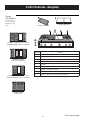
Control Features - Range
Design
information
(Not all features
are on all models.
Appearance may
vary.)
1
2
3
Grill and Griddle Covers
Bamboo Cutting Board
Toekick
6
4
7
5
8
9
ZDP486NR, ZDP486LR–6 burners and grill
ZDP486ND, ZDP486LD–6 burners and griddle
13
10
14
11
15
16
ZDP484NG, ZDP484LG
4 burners, grill and griddle
17
12
Double oven model shown includes a small oven.
ZDP364NR, ZDP364LR–4 burners and grill
ZDP364ND, ZDP364LD–4 burners and griddle
ZDP366N, ZDP366L
6 gas burners
ZDP304N, ZDP304L
Number
Feature
1
Bamboo
Feature
Index Cutting Board
Page
Cutting Board
37
2 1 Bamboo
Toekick
2
Toekick
——
3
Grill and Griddle Covers
3 Grill and Griddle Covers
——
4
Oven Vents
4 Oven Vents
17
5 5 IR (Infrared)
IR (Infrared)
Grill
Grill
12, 13
6 6 Grill Grill
and Griddle
and Griddle
GreaseGrease
TroughsTroughs
37
7 7 Griddle
Griddle
14
8
Cooktop
Burner
Grates
11,
36
8
Cooktop Burner Grates
9
Burner
Location
Indicator
——
9
Burner Location Indicator
10 LED Bullnose Task Lighting Control
——
10
LED Bullnose Task Lighting Bezel
11 Burner Control Knob with Lighted Bezel
11, 30
1112 OvenBurner
DisplayControl Knob with Lighted Bezel
16
1213 Mini-Knob
Oven Display
(to select
PROBE,(to
TIMER
or Special
Features)
30
13
Mini-Knob
select
PROBE,
TIMER, or Special16,Features)
14 Oven Mode Selector
16
14
Oven Mode Selector
15 Oven Temperature Knob
16
15
Oven Temperature Knob
16 Kitchen Timer
16, 28
1617 Leveling
Kitchen
Timer
System
(4)
17
Leveling System (4)
– 11 –
(Continued next page)
Oven Control and Timer
5
1. Oven Mode Selector – Turn outer ring to select:
PROOF – Maintains a warm environment useful
for rising yeast-leavened products.
4
3
BAKE – Select for traditional baking.
CONV BAKE – Use for convection baking.
1
CONV ROAST – Use for convection roasting.
2
CONV BROIL – Use for convection broiling.
BROIL – Select for broiling.
CLEAN – Select for the self-cleaning function.
See the Self-Cleaning Oven section.
The Oven Mode Selector (1) AND the Temperature
Knob (2) must be set together in one of the following
valid pairings:
2. Temperature Knob – Turn to select:
Temperatures from 175°F to 550°F.
LOW BROIL – A lower broiling temperature is
automatically set.
HIGH BROIL – A higher broiling temperature is
automatically set.
CLEAN – The self-clean temperature is
automatically set.
1. Mini-Knob – Turn to select and push to enter
PROBE or TIMER settings. Also to adjust CLEAN cycle
time.
2. Timer Button – Push to select the kitchen
timer function. The timer does not control oven
operations.
3. Oven Display – Displays oven functions such as
oven and probe temperatures and kitchen timer.
Oven Mode Selector
Temperature Knob
BAKE
175º to 550°F
CONV BAKE
175º to 550°F
CONVECTION/ROAST
175º to 550°F
CONVECTION/BROIL
HIGH or LOW BROIL
BROIL
HIGH or LOW BROIL
CLEAN
CLEAN
PROOF
――
To cancel a feature, turn either the Oven Mode
Selector or the Temperature knob to OFF.
To cancel PROOF, turn the Oven Mode Selector to
OFF.
– 12 –
(Continued next page)
How to Set the Oven for Baking
1. Turn the Oven Mode Selector to BAKE.
2. Using the Temperature knob, set the desired temperature, in 25°F increments, from 175°F to 550°F.
Oven Mode Selector
(Outer)
Oven Temperature Knob
(Inner)
The oven will now begin to preheat. The temperature display will begin at 100ºF and remain there until the
oven exceeds that temperature. From that point, the display will show the actual temperature.
The interior lights will turn on and stay on until the oven is turned off. The convection oven fan will turn on
temporarily during preheat. The control will beep when the oven is preheated and food can now be placed
inside the oven.
3. Turn the Oven Mode Selector and the temperature knob to OFF when baking is finished.
Note: A cooling fan will turn on to cool internal parts. This is normal, and the fan may continue to run even
after the oven is turned off.
Use the temperature probe when a precise internal temperature is important. See Owner's Manual.
– 13 –
(Continued next page)
How to Set the Oven for Broiling and Convection Broiling
1. Turn the Oven Mode Selector to BROIL or CONV BROIL.
2. Turn the Oven Temperature Knob to LO BROIL or HI BROIL. LO or HI will appear in the display.
Oven Mode Selector
(Outer)
Oven Temperature Knob
(Inner)
Note: Always broil with the door closed. If the door is left open, the display will scroll “CLOSE door” and the
elements will not turn on until the door is shut.
The oven interior lights will turn on and stay on until
the oven is turned off.
The convection fan will turn on when CONV BROIL is
selected.
3. When broiling is finished, turn the Oven Mode
Selector and the Temperature knob to OFF.
Open door broiling is
not permitted.
Note:
•
Broil will not work if the temperature probe is
plugged in. Never leave your probe inside the oven
during a broil cycle.
•
A cooling fan will turn on to cool internal parts. This is normal, and the fan may continue to run even after
the oven is turned off.
The broiler does not need to be preheated for most broiling. However, foods that cook quickly, such as thin
strips of meat or fish may require a short preheating period of approximately 5 minutes to allow the food to
brown. Turn the food only once during broiling.
– 14 –
(Continued next page)
Introduction to Convection Cooking
The Monogram reverse-air convection system
consists of two dedicated heating elements
wrapped around the convection fan. After
preheating to the set temperature, all heat in CONV
BAKE mode comes from these two dedicated
elements. The convection fan periodically pauses,
then changes direction to best distribute hot air
throughout the oven. As a result, foods are evenly
cooked and browned―often in less time with
convection heat.
Note: The convection fan shuts off when the oven
door is opened.
How to Set the Oven for Convection Baking or Roasting
Convection Baking is ideal for evenly browned baked foods cooked on single or multiple racks. Select
Convection Roast to roast large, tender cuts of meat uncovered.
When set on CONV BAKE or CONV ROAST, the rear convection elements and the fan operate when the oven
is heating.
1. Turn the Oven Mode Selector to CONV BAKE or CONV ROAST.
2. Using the Temperature knob, set the desired temperature, in 25°F increments, from 175°F to 550°F.
Oven Mode Selector
(Outer)
Oven Temperature Knob
(Inner)
The oven will now begin to preheat. The emperature display will begin at 100°F and remain there until the
oven exceeds that temperature. From that point, the display will show the actual temperature.
The interior lights will turn on and stay on until the oven is turned off. The convection oven fan will turn on
during preheat. The control will beep when the oven is preheated and food can be placed inside the oven.
3. Turn the Oven Mode Selector and the Temperature knob to OFF when convection cooking is finished.
Note: A cooling fan will turn on to cool internal parts. This is normal, and the fan may continue to run even
after the oven is turned off.
Use the temperature probe when a precise internal temperature is important. See Owner's Manual.
– 15 –
(Continued next page)
How to Set the Oven for Proofing
How to Set the Oven for Cleaning
The proofing feature maintains a warm environment
which is useful for rising yeast-leavened dough.
Caution: See owner's Manual for Self-cleaning
safety precautions.
1. Turn the Oven Mode Selector to PROOF. The
display will show “PrF”. PROOF mode will not
operate when oven is above 125°F. The display
will scroll “too hot”. Allow the oven time to cool.
1. Turn the Oven Mode Selector to CLEAN.
2. Turn the Temperature knob to CLEAN.
The control automatically defaults to the
recommended clean cycle time of 5 hours. The
clean time may be adjusted to any time between
3 and 5 hours using the Mini-Knob. The display will
show the actual time remaining.
3. Push the Mini-Knob to start the CLEAN cycle. If
“CLOSE door” scrolls in the display, the self-clean
cycle has been selected but the door is not
closed. Close the oven door.
Mini-Knob
Turn to adjust
Push to select
For best results, cover the dough with a cloth or with
greased plastic wrap.
Use rack position B or C in the large oven. Use rack
position B in the companion oven. See Owner's
Manual.
The proofing feature automatically provides the
optimum temperature (95°F) for the proofing
process; therefore the Temperature knob does not
affect the proof temperature.
The symbol will flash as the oven door is locked. It
will not be possible to open the oven door during the
clean cycle.
The oven interior lights cycle on and off as
necessary to maintain optimum proof temperature
until the Oven Mode Selector has been turned to
OFF.
•
To avoid lowering the oven temperature and
lengthening proofing time, do not open the oven
door unnecessarily.
•
Check bread products early to avoid overproofing.
2. When proofing is finished, turn the Oven Mode
Selector to OFF.
4. After the clean cycle is complete and the oven
has cooled, “End” will show in the display and
the will turn off. Turn the Oven Mode Selector
and the Temperature knob to OFF.
To interrupt a clean cycle, turn the Oven Mode
Selector and the Temperature knob to OFF. When
the oven has cooled to a safe temperature, the
symbol will turn off indicating the door may be
opened.
An interrupted clean cycle cannot be restarted until
after the oven is cool enough for the door to unlock.
– 16 –
(Continued next page)
Oven Thermostat Adjustment
How to Set the Oven Timer
You may find that your new oven cooks differently
than the one it replaced. Use your new oven for a
few weeks to become more familiar with it. If you
still think your new oven is too hot or too cold, you
can adjust the thermostat yourself.
Note:
•
The timer is independent of all the other
functions and does not control the oven.
•
Although the electronic control has a timer, it
does not have a clock feature.
On double oven models, use the main oven controls
to enter the mode and to select the adjustment.
To set the timer:
To adjust the oven thermostat:
1. Push the TIMER button.
1. Push and hold the TIMER button and Mini-Knob
at the same time for 4 seconds until the display
shows “SF” (Special Features).
2. Turn the Mini-Knob to adjust any length of time
up to 12 hours and push to select it.
Mini-Knob
Turn to adjust
Push to select
Mini-Knob
Turn to adjust
Push to select
On double oven models, each oven control has
its own timer function. Each timer can be set
independently.
2. Turn the Mini-Knob counterclockwise until the
display scrolls “OFFSEt”. Push the Mini-Knob to
select the offset mode.
The control will beep with 1 minute remaining and
the display will show seconds until the timer counts
down to :00. When the timer reaches :00, the control
will beep 3 times followed by one beep every 6
seconds until the Mini-Knob is pushed.
3. Turn the Mini-Knob to adjust the oven
thermostat up to 35°F hotter or (-) 35°F cooler in
1°F increments.
3A. On double oven models, you can adjust
the thermostat of the companion oven by
turning the Mini-Knob above the companion
oven. Use the main oven Mini-Knob to select
that adjustment.
To cancel the timer:
1. Push the TIMER button.
2. Turn the Mini-Knob to :00 and push to select.
To adjust the timer after start:
1. Push the TIMER button.
2. Turn the Mini-Knob to a new desired time and
push to select.
Note: The timer cannot be used while the oven is
self-cleaning. (On double oven models, the timer for
the oven that is not in the self-cleaning mode may
be used.)
4. Push the Mini-Knob to select your choice
and exit the mode. If you do not wish to save
changes, push the TIMER button to exit at any
time.
Note: This adjustment will only affect Bake,
Convection Bake and Convection Roast
temperatures; it does not affect broiling or selfcleaning temperatures. The adjustment will be
retained in memory after a power failure.
Do not use thermometers, such as those found in
grocery stores, to check the temperature setting of
your oven. These thermometers may vary 20–40
degrees.
– 17 –
(Continued next page)
Sabbath Mode*
To set the Sabbath mode:
The Sabbath mode is designed for use on the Jewish
Sabbath and other Jewish holidays.
It can be used for baking only. It cannot be used for
any other cooking mode.
When the Sabbath feature is set, the oven light
and all audible beeps will be disabled. The feature
will also provide a random delay period, of
approximately 30 seconds to 1 minute, before the
oven will turn on once it is set to BAKE.
1. Push and hold the TIMER button and Mini-Knob
at the same time for 4 seconds until the display
shows “SF” (Special Features).
Mini-Knob
Turn to adjust
Push to select
2. Turn the Mini-Knob clockwise until the display
scrolls “SAbbAtH.” Push the Mini-Knob to select
the Sabbath mode.
3. Once “SAbbAtH” is selected, the display will
scroll “SAbbAtH ON”.
The Sabbath setting will control both ovens. The
symbol will appear in both oven display windows
indicating the Sabbath mode is set. The symbol
indicates the oven is overheating.
For double oven models, use the main oven control
to set the Sabbath feature for both ovens.
To Cancel the Sabbath Mode:
Repeat steps 1, 2 and 3. The display will scroll
“SAbbAtH OFF”.
The oven temperature may be adjusted at any time
by turning the temperature knob. There is a random
delay before the oven elements respond.
*Certified Sabbath Mode
– 18 –
Installation
Installation information is for reference only. See the
Installation Instructions shipped with the product for
complete details and before attempting to install the
range or rangetop.
Range Electric Supply
Caution: These ranges weigh up to 700 pounds.
Some disassembly will reduce the weight
considerably. Rangetops weigh up to 170 pounds.
Due to the weight and size of the range or rangetop,
and to reduce the risk of personal injury or damage
to the product:
This branch circuit is to be protected by a circuit
breaker or time delay fuse (50 amp for 48" ranges,
30 amp for 36" and 30" ranges).
•
TWO PEOPLE ARE REQUIRED FOR PROPER
INSTALLATION OF 36" AND 30" RANGES AND 36"
AND 48" RANGETOPS.
•
THREE PEOPLE ARE REQUIRED FOR PROPER
INSTALLATION OF 48" RANGES.
Gas Supply Range and Rangetop
The natural gas models are designed to operate at
5" water column pressure. For proper operation, the
pressure of the natural gas supplied to the regulator
must be between 7" and 13" water column.
The LP models are designed to operate at 10" water
column pressure. For proper operation, the pressure
of the LP gas supplied to the regulator must be
between 11" and 13" water column.
All models can be ordered to operate on NATURAL
or LP gas. Models ordered to operate on NATURAL
gas are shipped with an LP conversion kit. Models
ordered to operate on LP gas are shipped with a
NATURAL gas conversion kit.
High Altitude Conversion Kit - For operation
above 6,000 feet, order Part #WB28K10553. This
kit includes orifices for both LP and Natural gas
operation.
A manual shut-off valve in the gas line (not
provided), is to be installed in an easily accessible
location. Make sure the homeowner knows where
and how to shut off the gas supply to the range or
rangetop.
These ranges must be supplied with 208/240 volt,
60 Hz., and connected to an individual, properly
grounded branch circuit.
The receptacle must be a NEMA 14-50R device to
accept the 4-prong plug supplied with the range.
If the electrical service provided does not meet
the above specifications, it is recommended that a
licensed electrician install an approved outlet.
Rangetop Electric Supply
These rangetops must be supplied with 120 volt,
60 Hz., and connected to a dedicated, properly
grounded branch circuit protected by a 15 amp
circuit breaker or time delay fuse.
The power cord of this appliance is equipped with
a three-prong (grounding) plug which mates with a
standard three-prong grounding wall receptacle to
minimize the possibility of shock hazard from this
appliance.
If the electrical service provided does not meet
the above specifications, it is recommended that a
licensed electrician install an approved outlet.
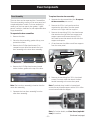
Backsplash Requirements
All models require 12" minimum clearance to a
vertical combustible surface at the rear. In a range
installation, if clearance is less than 12", the entire
surface of the back wall above and the full width
of the range must be protected by a backsplash.
In a rangetop installation, if clearance is less than
12", the entire surface of the back wall above the
countertop and the full width of the rangetop must
be protected by a backsplash. The backsplash must
be constructed of non-combustible material, such
as metal, ceramic tile, brick, marble or other stone.
WARNING: Installations without a hood require
48" minimum to combustibles. A custom hood
installation with exposed horizontal combustible
surfaces must have an Auto-On feature. Refer to
hood installation instructions for specific hood
clearances.
– 19 –
(Continued next page)
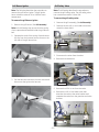
Leveling the Range
3. Use the supplied wrench to turn the front
leveling legs. Turn clockwise to raise the range
above the wheels. Turn counterclockwise to
lower the legs.
WARNING:
•
•
All ranges can tip. Injury could result. Install the
supplied Anti-Tip Bracket. See the instructions
included with the bracket.
4. Be sure to return the wrench to its storage slot
for future use.
The range must be level and be supported by
the legs―not the wheels. The range could move
if the wheels make contact with the floor. Be
sure all legs make contact with the floor in any
installation.
Rear leg adjustment:
1. Remove two screws from rear vent trim. Slide
vent trim forward, then lift up to remove.
2. Find the two rear leg extension rods. Use a 1/4in. driver or wrench to adjust the left or right rear
legs.
Note:
•
All legs must be leveled after the product is
installed.
•
Check to be sure the adjoining cabinets/
countertops are level, front to back and left to
right across the opening of the range.
•
Measure the distance from the floor to the top of
the countertop in the left and right rear corners.
•
Adjust the height of the range to countertop
height or higher.
Rear Vent Trim
Rear Leg
Extension Rod
IMPORTANT: This range should always be installed
at countertop height or higher. DO NOT INSTALL
THE RANGE LOWER THAN ADJACENT COUNTERTOP
HEIGHT. The range must be supported by all 4 legs,
regardless of countertop height.
3. Replace the rear vent trim using the original
screws.
Front leg adjustment:
A toe kick, that clips around the front leveling legs, is
supplied with each range. Customer use of the toe
kick is optional.
Range Toekick
Note: If toe kick is installed, pull to remove for
access to front leveling legs.
The toekick is installed after the range has been
leveled.
1. Slide front cylinders up to adjust front leveling
legs. Be careful not to damage cylinder.
2. A leveling leg wrench is supplied. Reach under
the front of the range near the right side. Locate
and remove a thumb screw, then slide wrench
out of the slot.
Thumb Screw
Toekick installation:
1. Measure the distance between the floor and the
bottom of range.
2. Loosen the two screws on each end. Adjust the
toekick height by sliding the upper and lower
pieces apart to 1/8" less than the measured
height.
Slide leg
cylinder up.
– 20 –
(Continued next page)
3. Secure the top and bottom sections by
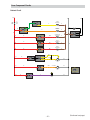
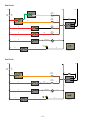
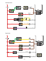
tightening the 2 screws on each end.
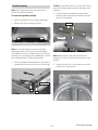
Range Anti-Tip Device
WARNING: All ranges can tip. BURNS or other
SERIOUS INJURIES can result. INSTALL and CHECK
the ANTI-TIP bracket following these instructions.
Top of
Toekick
To reduce the risk of tipping the range, the range
must be secured by a properly installed anti-tip
bracket. See installation instructions shipped with
the bracket for complete details before attempting
to install.
To check if the bracket is installed and engaged
properly, carefully tip the range forward. The
bracket should stop the range within 4 inches. If it
does not, the bracket must be reinstalled.
Bottom
of Toekick
If the range is pulled from the wall for any reason,
always repeat this procedure to verify the range is
properly secured by the anti-tip bracket.
Screw
4. Push toekick against range leg until clip snaps to
legs.
If your range has no anti-tip bracket, call
1.800.626.8774 to receive one at no cost.
Note: Be sure the toekick snaps securely to the leg.
If the Anti-Tip device supplied with the range does
not fit this application, use the universal Anti-Tip
device WB2X7909.
Read the AHAM Anti-Tip Safety Brochure packed
with the bracket.
Anti-Tip Parts Provided
Push
Push
4 Wood Screws
Anti-Tip Bracket
Push
Push
Rangetop Anti-Slide Bracket
WARNING: All rangetops can slide out. Injury could
result. When properly installed, a hold-down strap
with screws secures the rangetop to the rear or side
cabinet walls. See the instructions included with the
bracket.
3 Hex Head Screws
(2 required, 1 extra)
Anti-Tip Brace
AHAM Anti-Tip
Safety Brochure
Hold-Down
Strap
Location and
Attachment
Back Wall
– 21 –
(Continued next page)
Attach the Anti-Tip Brace onto the bottom of the
range in the recessed area. Install 2 hex screws
(provided) through the brace and into the range.
Gas Conversion Range and Rangetop
WARNING:
Note: This Anti-Tip device may be installed on the
opposite side of the range.
This conversion must
be performed by a qualified installer or gas supplier
in accordance with the manufacturer’s instructions
and all codes and requirements of the authority having
jurisdiction. Failure to follow instructions could result
in serious injury or property damage. The qualified
agency performing this work assumes responsibility
for the conversion.
WARNING:
The rangetop, as shipped from
the factory, is set for use with its intended gas. If you
wish to use your rangetop with the alternate gas, you
must first replace the orifices and convert the pressure
regulator.
Hex Screws
Anti-Tip Brace
WARNING:
Alternate Brace
Position
The following adjustments must
be made before turning on the burner. Failure to do so
could result in serious injury. Be sure pressure regulator
has been converted as described in Step 2.
1. Measure and mark Dimension A (see table
below) from the left (or right) side of the
installation location. If the countertop has an
overhang, add that dimension to Dimension A.
TOOLS YOU NEEDED FOR CONVERSION
1/4" and 7mm Nutdrivers
Crescent Wrench
2. Place the Anti-Tip Bracket against the floor and
back wall at the marked location. Mark screw
holes for fastening the bracket to the wall sole
plate and the floor.
Small Flat-Head Screwdriver
(2 to 2.4 mm or 3/32" tip size,
60 mm long)
Safety Glasses
3. Drill 1/8" pilot holes at a 20° angle.
4. Secure the bracket to the wall and/or floor with
at least 2 wood screws (provided).
1/2" Deepwell
Socket Wrench
For Concrete or Cement Construction: You must
use appropriate fastening hardware (not provided).
1 ORIFICE HOLDER
Griddle
Orifice
Philips
Screwdriver
Grill
Orifice
The range orifice holder
is located behind the front
access panel at the bottom
of the range.
Burner Orifices
The rangetop orifice holder
is located inside the range insulation cover.
Additional orifices may be present. Use only the orifices
specified in the instructions for your range or rangetop.
Anti-Tip Bracket
Wall Sole Plate
A
Range
30"
36"
48"
Small Pliers
A
5-1/16"
5-1/16"
8-1/4"
– 22 –
2 CONVERT THE REGULATOR
3 CHANGE BURNER ORIFICES (cont.)
IMPORTANT: Find your model number below. Read
each orifice label to identify and install them in the
exact locations shown.
Disconnect all electrical power at the main circuit
breaker or fuse box.
A. Remove the rear vent Range Regulator
trim (on ranges only)
to access the
regulator. The
Rangetop regulator is
on the left bottom
corner.
B. Shut off the gas supply by closing the manual shut-off
valve in the unit or at the wall.
C. Convert the pressure regulator:
• Unscrew the cap with plunger.
• Place your thumb against flat side of the plunger and
press down to snap the plunger out of the cap.
• Carefully look at the plunger to locate the NAT
or LP position.
A 34SL or 51SN orifice
will be used on all burners.
ZDP304 MAIN ORIFICES
Gasket
Cap
LP
NAT
NAT
A 84XL or
126HXN orifice
will be used
on these three
burners.
LP
NAT
LP
Plunger
LP
NAT
NAT. Position
LP Position
Use a 108XL
or 190XN orifice
for the right
front burner.
DOWN
FOR OFF
• Turn the
plunger
over so
that the
desired gas
is showing
near the
bottom.
ZDP304 SIMMER ORIFICES
Pressure Regulator
• Snap the plunger back into the cap.
• Screw the cap back onto the regulator.
ZDP364, ZDP366, ZDP484, ZDP486
SIMMER
ORIFICES
A 34SL or 51SN orifice
will be used on all
burners.
3 CHANGE BURNER ORIFICES
Burner Cap
INSTALLATION TIP: First remove all
orifices and then start replacing them.
This will help to prevent the possibility
that some may not be replaced.
Burner
A. Remove the burner grates,
Head
burner caps and burner heads.
B. Loosen the top burner
Spark
Igniter
orifices using a 7 mm
nut driver. Use small
Burner Base
pliers to carefully lift out the orifices.
The main orifice is located
low in the center of the
burner, while the simmer
Simmer
orifice is located higher
Orifice
beside the center
of the burner.
Main
MAIN
ORIFICES
Use 108XL or
190XN orifices
for all burners.
A. Return the unused orifices to the holder. Reattach
the holder and the instruction sheet with screw
in the original storage location.
B. Replace the burner heads, caps and top grates.
On range models, replace rear vent trim.
Orifice
– 23 –
(Continued next page)
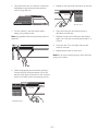
5 CHANGE GRIDDLE ORIFICE (if present)
4 CHANGE GRILL ORIFICE (if present)
Locate the 3/4" long Griddle orifice.
Select for your gas type. LP—.047, NAT—.076
Locate the 1–1/2" long Grill orifice.
Select for your gas type. LP—.047, NAT—.067
A. Lift off
the griddle flue
cover. Remove
Griddle Flue Cover
the 2 inside
A
clamping
screws.
B. Use a pad or
piece of
carton to
protect
Leveling Screws
the adjacent
surface. Slide
the griddle
Clamping Screws
toward
the rear
and out of
B
the hold-down tabs along
the bottom.
C. CAREFULLY lift and hold
the griddle. A thermostat
capillary is routed through
a clip. Gently lift the griddle
to one side and slip the
capillary out of the clip.
C
D. Lay the griddle
on the padded surface.
Do not disconnect or pull
on the capillary.
E. Remove the 2 burner
hold-down screws
at the rear of the burner.
D
• Pull the burner straight
back toward the rear
and out of the gas inlet.
F. Use a 1/2" deep well socket
to remove and replace
the orifice.
A. Remove the grill cover,
grates and grate frame. Lift
the radiant baffle straight
up and off.
B. Remove the 2 hex
head screws from
2
the top of the igniter. Remove
hex head
screws
• Remove one screw
from each side of
the burner surround.
• Lift out the surround.
Surround
Screws
Burner
C. Carefully push the
Surround
igniter aside and
under
the burner.
Do not pull or pinch
the wire.
Remove 4 burner
attachment screws,
2 at the front and 2
at the back. Slide the
burner assembly
toward the back and
out of the gas inlet.
D. Use a 1/2" deep well
socket to remove
and replace the orifice .
Reverse these
steps to re-assemble
the grill. Be sure to
place the unused
orifice in the holder
for possible future use.
Igniter
Burner
Assembly
E
Back of Range
F
NOTE: Remove
the 2 screws
positioned on
the inside only.
Do not remove
the outermost
screws—they
are for leveling.
Capillary
Front of Range
Front of Range
Reverse these steps to re-assemble the griddle. Push excess
capillary back into the entry hole. Route the thermostat
capillary so it is held by the clip. Place the unused orifice in
the holder for possible future use.
– 24 –
(Continued next page)
Oven Operational Notes
6 ADJUST BURNER FLAMES
Certain modes, when selected, will automatically
enter into a preheat. The temperature knob is used
to set the desired temperature, in 25°F increments,
from 175°F to 550°F. The oven will now begin to
preheat. The temperature display will begin at
100ºF and remain there until the oven exceeds that
temperature. From that point, the display will show
the actual temperature.
Normally, burners do not need further adjustment.
Make adjustments only when necessary.
A. Turn on the gas. Plug in electrical cord.
B. Turn all burners on highest setting and check
the flames. They should be blue in color. When
using LP gas, the flames may have some yellow
tipping at the ends of the flame. Foreign particles
in the gas line may cause an orange flame at first,
but this will soon disappear.
C. Turn the burner knob to “LO” while observing the
flame.
Adjust the setting of the upper row of flames using
the valve bypass screw as follows:
Adjustments must be made with two other burners
in operation on a medium setting. This prevents
the upper row of flames from being set too low,
resulting in the flame being extinguished when
other burners are turned on.
D. To adjust the flame, remove the knobs. Insert a small
flat-blade screwdriver into the hole in the center
of the valve stem to engage screw.
The interior lights will turn on and stay on until the
oven is turned off. The convection oven fan will turn
on temporarily during preheat. The control will beep
when the oven is preheated and food can be placed
inside the oven.
Note: A cooling fan will turn on to cool internal
parts. This is normal, and the fan may continue to
run even after the oven is turned off.
Preheat Chart
Mode
• If the flames are too small or flutter,
turn the screw counterclockwise.
• If the flames are too large, turn the screw
clockwise.
E. Make the adjustment by slowly turning the screw
until flame appearance is correct.
Note: Once the conversion is complete and checked,
fill out the conversion label and affix the label near
the rating label. For ranges, place the label beneath
the control panel. For rangetops, place the label on
the bottom of the unit.
Preheat
Proof
No
Bake
Yes
Convection Bake
Yes
Convection Roast
Yes
Convection Broil
No
Std Broil
No
Clean
No
Sabbath Mode
No
Probe Usage
Yes
•
Preheat operation consists of multiple phases,
which are time and/or temperature dependant.
Each phase of preheat utilizes combinations of
inner and outer bake, broil, and inner convection
elements. For example, one phase may use
inner convection and outer broil simultaneously.
Another phase may use inner broil and outer
bake simultaneously.
•
At the start of Preheat, the convection fan
will delay running for 10 seconds. It will then
run CCW with no directional changes for the
remainder of Preheat.
– 25 –
•
The convection fan will cycle on and off while
cooking to best distribute hot air in the oven. The
convection fan shuts off when the oven door is
opened.
•
Different broil elements are used in each broil
mode. There are 2 different broil modes, each
providing a HI and a LO setting.
•
The Convection Broil mode uses both the inside
and outside broil elements and convection fan.
•
Broil will not work if the temperature probe is
plugged in.
•
When using the probe, you can use the timer,
but you cannot use timed oven operations.
•
In Convection Bake, both the inner and the outer
convection elements cycle and the fan operates
whenever the oven is heating.
•
Convection Broil will not work if the temperature
probe is plugged in. Never leave your probe
inside the oven during a broil cycle.
•
The Clean cycle can be set for a minimum of 3
hours and a maximum of 5 hours. The default
setting is 5 hours. The 5-hour set time consists
of 4 hours and 15 minutes of cleaning and 45
minutes of cool down. The door will unlock at an
approximate temperature of 450°F.
•
On double oven models, the ovens can be set to
self clean in sequence. The first oven set starts
the cycle. The second oven will start cleaning
as soon as the first oven has cooled to 550°F (it
should already be below 550°F at the end of a
standard 5-hour clean since a 45 cool-down is
included in the time). If the first oven clean cycle
is cancelled, the second oven will start cleaning
immediately or as soon as the first oven cools
below 550°F.
•
Self-Clean will not work if the temperature probe
is plugged in or if the Sabbath feature is set.
•
Proofing will not operate when oven is above
125°F. The display will show “too hot”. Allow the
oven time to cool.
– 26 –
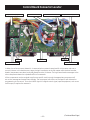
Component Locator Views
Front of Range (48-in. range shown)
Rangetop
Task
Light
Switch
Control
Panel
Broil Element
Broil Element
Lights
Lights
Lights
Convection Fan
Convection Fan
Oven Door Gasket
Oven Door Gasket
Oven Door
Oven Door
– 27 –
(Continued next page)
Rear of Range (48-in. range shown)
Level Leg Extension Rod
Level Leg Extension Rod
Regulator
Shutoff Valve
Sail Switch
Sail Switch
Cooling Fan
Cooling Fan
Broil Element
Oven TCO
Broil Element
Oven TCO
Convection Fan
Convection Fan
Convection Element
Convection Element
Terminal Block
Gas Inlet Pipe
– 28 –
(Continued next page)
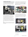
Rangetop ZGU484NG
LED Task
Lighting
Control
IR (Infrared) Grill
Griddle
IR (Infrared) Grill Control
Knob with Lighted Bezel
Griddle Control Knob
with Lighted Bezel
Burner Control Knob
with Lighted Bezel
(1 of 4)
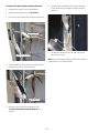
Rangetop ZGU484NG (burner pans, top heat barriers, grill, and griddle removed)
Grill Burner Igniter
Burner
Burner
Spark Module
Griddle Burner
Grill Burner
Griddle Burner Igniter
Burner
Burner
Transformer
Surface Burner Valve
IR (Infrared) Grill Control
– 29 –
Surface Burner Valve
Griddle Control
Surface Components
WARNING: Sharp edges may be exposed when
servicing. Use caution to avoid injury. Wear Kevlar
gloves or equivalent protection.
3. Remove the 2 Phillips-head screws within each
bezel that attach the bezel to the manifold
brackets.
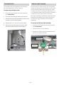
Control Panel
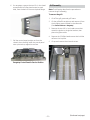
It is necessary to remove the control panel from the
range or rangetop chassis and place it in the service
position to access certain components.
To place the control panel in the service position:
Note: It will be necessary to pull the rangetop
approximately 10 inches out from its installation.
1. Remove left and right side grates, surface
burner knobs, grill and griddle control knobs.
2. On range models:
a. Remove the 2 Phillips-head screws that
attach the griddle control bezel to the
control panel.
b. Remove the 2 Phillips-head screws that
attach the griddle control to the manifold
bracket.
Bezel Screw
4. Remove the T-15 Torx screws from the bottom
of the control panel.
5. Remove the Phillips-head screw at each front
corner that attaches the front of the side trim to
the control panel.
Control Screw
Note:
Control Screw
Bezel Screw
•
A ground wire at each end of the panel allows
the panel to be lowered without falling.
•
Before lowering, protect the bottom of the front
panel from scratches caused by the lock motor
arm (range models) or front frame edge.
•
If the range has a grill, use caution when
lowering the control panel to prevent damage to
the switches mounted at the bottom of the grill
valve.
– 30 –
(Continued next page)
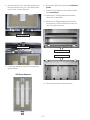
6. On rangetops, remove the two 1/4-in. hex-head
screws and the Phillips-head screw (on each
side), from the back of the control panel flange.
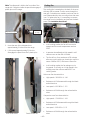
Grill Assembly
Note: The following describes the procedure to
remove the grill assembly.
To remove the grill:
1. Lift off the grill grate and grill frame.
2. Lift the grill baffle straight up and remove it from
the 4 support posts located on the side walls.
(See Control Features - Rangetop.)
3. Remove the two 1/4-in. hex-head screws that
attach the igniter to the igniter bracket, then
place the igniter aside.
4. Remove the 2 Phillips-head screws that hold the
reflector trim in place.
7. Pull the control panel straight out from the
chassis, then carefully lower the control panel
onto a protective, supportive surface.
5. Lift up and remove the trim and screen.
Rangetop Control Panel in Service Position
– 31 –
(Continued next page)
6. Remove the two 1/4-in. hex-head screws from
the front and the two 1/4-in. hex-head screws
from the rear of the grill burner.
8. Remove the grill burner igniter. (See Grill Burner
Igniter.)
9. Place the control panel in the service position.
(See Control Panel.)
10. Remove the 2 Phillips-head screws and the
center trim, if applicable.
11. Remove the 2 Phillips-head screws from the
front and the 2 Phillips-head screws from the
rear of the grill burner box.
Front of Grill Burner
Rear of Grill Burner
Front of Grill Burner Box
Rear of Grill Burner Box
7. Lift up and maneuver the grill burner past the
igniter bracket.
Grill Burner Removed
11. Lift up and remove the grill burner box.
– 32 –
Grill Burner Igniter
Note: The following describes the procedure to
remove the grill burner igniter. The grill igniter
has a resistance value of 45 to 400 Ω at room
temperature.
To remove the grill burner igniter:
1. Remove the grill burner. (See Grill Assembly.)
Note: In the following step, ensure that the spring
clip is captured and retained inside the grill burner
box.
Grill Safety Valve
Note: The following describes the procedure to
remove the grill safety valve. The grill safety valve
has a resistance value of 1 Ω or less.
To remove the grill safety valve:
1. Remove the grill assembly. (See Grill Assembly.)
2. Remove the two 1/4-in. hex-head screws that
attach the heat shield.
2. Squeeze the ends of the spring clip and retract
the clip from the harness access cutout on the
left side of the grill burner box.
Heat Shield
3. Disconnect the wires from the valve.
Spring Clip
4. Remove the heat barrier.
Disconnect
Disconnect
3. Pull the harness connector thru the cutout and
disconnect the igniter wire harness.
Heat Barrier
5. Remove the 9/16-in. nut from the valve.
6. Remove the 1/4-in. hex-head screw that
attaches the valve to the valve bracket and
separate the valve from the gas tube and valve
bracket.
– 33 –
Grill Control
The grill control is attached to the manifold bracket.
A switch bracket is attached to the control and
secures 2 switches. The front switch controls
the igniter and the rear switch controls the LED
indicator. When the Grill knob is turned to the
ON position, both switches close contacts. Both
switches can be replaced separately.
4. Using a ratchet wrench, remove the 1/4-in.
hex-head screw that attaches the control to the
manifold.
To remove the grill control switches:
1. Place the control panel in the service position.
(See Control Panel.)
2. Carefully press the 2 locking tabs away from
the switches and remove the switches from the
switch bracket.
3. Mark and disconnect the wires from the 2
switches.
5. Separate the control from the gas outlet tube
and manifold.
Caution: Ensure the control seal and the screw seal
are in place BEFORE installing the control.
Note: Switch mounting bracket is a part of the valve
assembly.
Tab
Control Seal
Tab
Switch Mounting
Bracket
Screw Seal
To remove the grill control:
1.
Remove the grill control switches.
2. Remove the grill assembly. (See Grill Assembly.)
3. Remove the 5/8-in. nut from the grill control gas
outlet tube.
– 34 –
Caution: The griddle is heavy. Use care when lifting
and rotating the griddle to prevent damage to the
capillary.
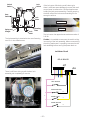
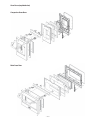
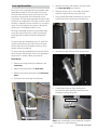
Griddle Assembly
Note: The following describes the procedure to
remove the griddle assembly.
4. Lift and rotate the griddle and remove the 2
Phillips-head screws and the retainer from the
bottom of the griddle.
To remove the griddle assembly:
1. Remove griddle flue cover and grease trough.
2. Remove the (inner) clamping screws.
Retainer
Capillary
Note: It’s recommended to remove the griddle
completely when servicing the burner assembly.
The griddle control has a capillary that is positioned
securely to the underside of the griddle by a retainer
that is attached with 2 Phillips-head screws.
3. Push the griddle toward the back of the range to
release tabs from slots on the front of the range.
Note: When installing the retainer, ensure the
capillary is in direct contact with the bottom of the
griddle.
5. Remove the two 1/4-in. hex-head screws from
the back of the grill burner.
Front of Range
Tab
Slot
– 35 –
(Continued next page)
Note: In the following step, ensure that the spring
clip is captured and retained inside the griddle
burner box.
13. Remove the 2 Phillips-head screws from the
front and the 2 Phillips-head screws from the
rear of the griddle burner box.
6. Squeeze the ends of the spring clip and retract
the clip from the harness access opening on the
right side of the griddle burner box.
7. Lift the burner and pull the igniter wiring and
harness connector through the opening.
8. Disconnect the igniter wire harness connector
and remove the two 1/4-in. hex-head igniter
screws.
Front of Griddle Burner Box
Rear of Griddle Burner Box
Griddle Burner Removed
15. Lift the burner box while carefully guiding the
igniter wire harness connector and control
capillary through their openings.
9. Remove the grease trough.
10. Remove the 4 Phillips-head screws that attach
the rear trim.
11. Place the control panel in the service position.
(See Control Panel.)
12. Remove the 2 Phillips-head screws and the
center trim, if applicable.
– 36 –
Griddle Burner Igniter
Griddle Control
The griddle burner igniter is attached to the right
side of the griddle burner with two 1/4-in. hexhead screws. It is necessary to remove the griddle
burner (See Griddle Assembly.), to access the screws
and the igniter wire harness. The griddle igniter
has a resistance value of 45 to 400 Ω at room
temperature.
The control utilizes a capillary that senses griddle
temperature and a switch that operates the LED
indicator light. When the griddle knob is turned to
the ON position, the control closes contacts that
start the ignition process. The LED switch contacts
also close and activate the LED indicator light. The
LED switch can be replaced separately.
On rangetops, the griddle control is attached to a
bracket that is held in place inside the front panel.
Griddle Safety Valve
Note: The following describes the procedure to
remove the griddle safety valve. The griddle safety
valve has a resistance value of 1 Ω or less.
To remove the griddle safety valve:
1. Place the control panel in the service position.
(See Control Panel.)
3. Disconnect the 2 wires from the valve.
4. Remove the heat barrier.
5. Remove the 9/16-in. nut from the valve.
On ranges, the griddle control is attached to a
manifold bracket.
To remove the griddle control:
1. Remove the griddle, then remove the capillary
retainer. (See Griddle Assembly.)
Note: On range models, it’s a tight fit between the
manifold bracket and the front frame of the range.
2. Remove the 2 Phillips-head screws and the
griddle control from the control bracket
(rangetops), or manifold bracket (ranges).
3. Place the cardboard insulator aside.
Disconnect (1 of 2)
Heat Barrier
6. Remove the two 5/16-in. hex-head nuts that
attach the valve to the chassis, then separate
the valve from the chassis and gas tube.
Cardboard Insulator
4. Slide the LED switch and switch plate off the
control shaft.
LED Switch
and Switch
Plate
– 37 –
(Continued next page)
5. Slide the switch off the switch plate.
LED Switch
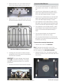
Grill and Griddle Ignition Systems
The grill and griddle burners are ignited by a glowbar ignition system. The igniter is a Norton style
rectangular glow-bar. The grill and griddle ignition
circuits consist of the control, an igniter, a hi limit
switch (griddle only), and a safety valve. These
components are wired in series for each cooking
function.
The most important points to know about the
ignition system are:
Switch Plate
6. Remove wires from the LED switch.
•
THE IGNITER RESISTANCE DECREASES AS THE
IGNITER SURFACE TEMPERATURE INCREASES.
•
THE SAFETY VALVE OPERATES BY CURRENT, NOT
VOLTAGE.
From a cold start, the igniter needs 30 to 60
seconds, with a minimum of 116 volts applied, to
reduce its electrical resistance enough to provide a
minimum of 2.9 amps of current flow in the series
circuit. This is the required current flow needed
for the safety valve to open and supply gas to the
burner.
7. Remove wires from the control.
The glow-bar should provide a steady current flow
of 3.4 to 3.6 amps (3.03 / 3.3 VAC) in the circuit. At
that point, the igniter temperature is 1800°F to
2500°F (982°C to 1371°C). The igniter will remain
energized at all times during burner operation. If
the igniter glows red but does not draw at least 2.9
amps, the fault is usually with the igniter, not the
valve.
Always check the gas shut-off valve located next to
the pressure regulator for a Not On condition.
8. Slide the capillary out of the griddle burner box.
– 38 –
Surface Burner Base
Glow-bar Igniter
WARNING: The range and rangetop use rectangular Norton glow-bar igniters. They are NOT
INTERCHANGEABLE with cylindrical Carborundum
glow-bar igniters. The two types of glow-bar igniters
operate at different amperage and use different gas
valves.
Note: The following describes the procedure to
remove a single burner base. The procedure to
remove the remaining burner bases is identical.
To remove the burner base:
1. Lift off the burner grates, cap, and burner head.
Check the glow-bar circuit with a clamp-on
ammeter. If igniter glows red but circuit does not
draw at least 2.9 amps, the fault is likely with the
igniter, not the valve.
Note: Five T-15 Torx screws attach the surface
burner: 3 coarse thread screws on the outside, and
2 fine thread screws on the inside.
Note: If igniter glows, but ignition does not occur, be
sure the gas shut-off valve on the pressure regulator
is in the open position.
2. Remove the three T-15 Torx screws that attach
the burner base to the burner pan and the two
T-15 Torx screws that attach the burner base to
the burner.
Slow ignition can be caused by one or more of the
following conditions:
1. Blockage of primary air intake: Inlet slots under
bullnose (near LED light locations) must be open.
2. Blockage of secondary air intake holes:
Examine grill and griddle burner boxes (galvanized box surrounding burner) and inspect the
secondary holes beneath the burner for signs of
blockage.
3. Improper alignment of orifice hood and burner:
Orifice must be pointing straight into burner
venturi.
4. Improper air/gas adjustment.
5. Blockage of griddle burner gas exit holes.
Internal restriction or partial restriction inside
the grill burner assembly.
6. The ignitor should draw approximately 3.4 to 3.6
amps when operating. To check, carefully use a
clamp-on ammeter at one of the igniter leads.
Caution: When removing the wire from the igniter,
make sure you do not damage the heat shrink
insulation on the wire. If damaged, repair the wire
insulation with fiberglass tape.
3. Lift each burner base, note the color of the
igniter wire, then disconnect the igniter wire.
Grill Igniter Circuit Test
Igniter Wire
– 39 –
Surface Burner Igniter
Surface Burner Pan
Note: The following describes the procedure to
remove a single igniter. The procedure to remove the
remaining igniters is identical.
To remove the igniter:
1. Remove the burner base. (See Surface Burner
Base.)
2. Use a small needle-nose pliers and remove the
clip and spring from the igniter.
Ranges
The following procedure describes the removal of
the left-side surface burner pan on range models.
The procedure to remove the right-side burner pan
is similar.
Note: On the 36-in. six surface burner range, the
pan is one piece and will require the removal of one
side panel. (See Side Access Panel.) Then follow steps
#1 through #4, #6 and #7 to remove the burner pan
from under the remaining side panel.
To remove the left-side surface burner pan:
1. Place the control panel in the service position.
(See Control Panel.)
Igniter
2. Lift off all the grates.
3. Remove the burner bases from the pan. (See
Surface Burner Base.)
Clip
Spring
4. Remove the Phillips screws on the front of the
oven vent, then pull the vent toward the front to
release a tab at each end.
3. Pull out the igniter from the burner base.
5. Remove the adjacent grill/griddle. (See Grill
Assembly or Griddle Assembly.)
6. Remove the Phillips-head screws that attach the
burner pan.
Caution: The burner pan has a lip that is captured
under the left-side panel. To prevent scratching or
chipping the pan, use extreme care when removing
or installing the burner pan.
– 40 –
(Continued next page)
7. Lift and tilt the right side of the burner pan, then
carefully slide it out from under the left-side
panel.
Surface Burner
Note: The following describes the procedure to
remove a single burner. The procedure to remove
the remaining burners is identical.
To remove the burner:
1. Remove the burner base. (See Surface Burner
Base.)
2. Remove the surface burner pan. (See Surface
Burner Pan.)
3. Remove the heat barrier by lifting it out of the
burner box.
Rangetops
Heat Barrier
The following procedure describes the removal of a
surface burner pan on rangetop models.
Note: On the 36-in. six surface burner rangetop, the
pan is one piece and will require removal of all six
burner bases, side, and rear trims. Then, follow steps
#1 and #5, to remove the pan.
Heat barrier as viewed from side
To remove the surface burner pan:
4. Remove the 9/16-in. nut and separate the main
gas tube from the burner.
1. Place the control panel in the service position.
(See Control Panel.)
5. Remove the 7/16-in. nut and separate the
simmer gas tube from the burner.
2. Lift off the adjacent grill/griddle grates.
6. Remove the two 1/4-in. hex-head screws that
attach the burner to the burner bracket.
3. Remove the burner bases from the pan. (See
Surface Burner Base.)
4. Remove the Phillips-head screws, back trim, and
side trim over the pan to be removed.
5. Remove the Phillips-head screws that attach the
burner pan.
Simmer Gas Tube
Burner
Caution: The burner pan has a lip that is captured
under the adjacent grill/griddle. To prevent
scratching or chipping the pan, it may be helpful
to loosen the adjacent grill/griddle burner box. (See
Grill Assembly or Griddle Assembly.) Use extreme care
when removing or installing the burner pan.
6. Lift and tilt the side opposite the adjacent grill/
griddle and slide it out from under the adjacent
grill/griddle.
Main Gas Tube
– 41 –
5. Slide down and remove the wiring retainer clip
from the frame.
Surface Burner Valve and Switch
Each surface burner valve utilizes a switch. When a
burner knob is turned to the ON position, the valve
switch closes and activates the spark module and
the LED light. Each surface burner valve switch is
installed on the front of the burner valve body. The
switches are all wired to a single harness and are
replaced as one assembly. It is necessary to remove
the valve to access the switch.
6. Using a ratchet wrench, remove the 1/4-in.
hex-head screw that attaches the valve to the
manifold.
Clip
Note: The following describes the procedure to
remove a single burner valve and switch. The
procedure to remove the remaining valves and
switches is identical.
To remove the surface burner valve and switch:
1. Remove the burner pan located over the valve
and switch to be replaced. (See Surface Burner
Pan.)
7. Maneuver the valve below the bracket and slide
the valve switch from the valve stem.
2. Remove the heat barrier by lifting it out of the
burner box.
3. Remove the 7/16-in. nut and the 9/16-in. nut
from the valve.
Valve Switch
Valve Stem
Caution: Ensure the valve seal and the screw seal
are in place BEFORE installing the valve.
Valve Seal
4. Remove the Phillips-head screw and the
indicator light assembly from the valve bracket.
(See Indicator Light Assembly.)
Screw Seal
Note: The bottom of each switch is molded to
conform to the front of the valve for a locked-in fit.
For proper igniter operation, each switch must be
locked-in to the top of the valve. When installing
the switch, align each switch to the valve stem and
body. Push the switch down firmly until an audible
"snap" is detected.
– 42 –
5. Remove the 2 Phillips-head screws that attach
the module to the burner box.
Spark Module
The spark module is located under the left-side
surface burner pan.
6. Remove the Phillips-head screw that secures the
module wire harness.
To remove the spark module:
7. Mark and disconnect the igniter wires and
disconnect the wire harness from the spark
module.
1. Remove the left-side surface burner pan. (See
Surface Burner Pan.)
2. Remove the three 1/4-in. hex-head screws that
attach the module cover to the burner box.
3. Remove the two 1/4-in. hex-head screws that
attach the left rear burner to the burner bracket.
4. Lift the left rear burner and maneuver the
module cover out from the burner box.
– 43 –
6. Maneuver the transformer to the right, then
rotate the bracket forward to the horizontal
position.
Transformer
The transformer is located under the left-side
surface burner pan. The transformer windings have
an approximate resistance value between:
7. Disconnect the (secondary) wiring connector
from the transformer harness that is retained in
the harness bracket.
Brown to brown (120 VAC primary) - 33 Ω
Brown to red (240 VAC secondary) - 188 Ω
8. Using a flat blade screwdriver, push on the 2
tabs and remove the transformer (secondary)
wire harness from the harness bracket.
To remove the transformer:
1. Remove the left-side surface burner pan. (See
Surface Burner Pan.)
2. Lift and peel back the front of the heat barrier to
expose the transformer's front mounting screw.
3. Remove the two 1/4-in. hex-head screws that
attach the transformer to the burner box.
4. Disconnect the surface burner igniter switch
wire harness.
5. Remove the top screw from the harness bracket.
Tab
Transformer
Wire Harness
Tab
Bracket
Transformer
9. Disconnect the (primary) wire harness.
Disconnect
– 44 –
On range models, the LED power supply is located
above the surface burner manifold on the left side
of the control area. It is accessible by placing the
control panel in the service position. (See Control
Panel.) The power supply is held in place with four
1/4-in. hex-head screws.
LED Lights and Power Supply
The LED lights (task lighting) are located inside the
control panel and are positioned to provide light
over each bezel when activated by the task light
switch.
LEDs Activated
On rangetops, the LED power supply is located
below the left-side surface burners. It is accessible
by removing 2 Phillips-head screws that attach an
access plate located on the bottom of the rangetop.
The power supply is held in place with 4 Phillipshead screws.
Each light is an assembly that consists of an LED
and circuit board attached to a metal bracket
with a Phillips-head screw. Each bracket is placed
into a channel inside the top of the control panel.
Loosening the bracket set screw allows the
assembly to slide along the channel in order to be
removed or positioned directly over each bezel. The
circuit boards are wired in series to a light harness
and are replaced as one unit. If one light assembly
fails or a wiring connection is loose, all LEDs will be
out.
Note: When replacing task lighting, make sure each
light is centered over each bezel before installing the
control panel.
Power Supply Connections
J1
J2
J3
J1 - Input (120 VAC)
J2 - LED Output
J3 - Light Switch
– 45 –
(Continued next page)
Task Light Switch
Indicator Light Assembly
The task light switch is attached to the left side of
the control panel with a 3/4-in. hex nut.
Each surface unit (surface burner, grill, and griddle),
utilizes an indicator light consisting of a circuit board
with an attached Light Emitting Diode (LED). When
a surface unit knob is turned to the ON position, the
circuit board activates the LED and light is directed to
the indicator lens of that surface unit's bezel.
To replace the task light switch:
1. Place the control panel in the service position.
(See Control Panel.)
3. Remove the wire ties that attach the switch wire
harness to the LED wire harness,
Each light assembly is attached to a manifold valve
bracket and connected to the valve switch wiring
harness. Each light assembly can be replaced
separately.
4. Remove the 3/4-in. hex nut from the switch.
To remove the indicator light assembly:
5. Slip the nut over the harness connector, then
remove the switch from the control panel.
1. Place the control panel in the service position.
(See Control Panel.)
2. Disconnect the task light switch wire harness,
2. Disconnect the LED wire harness.
3. Remove the Phillips-head screw that attaches
the LED to the valve bracket.
Disconnect
Nut
Indicator Light
Assembly
– 46 –
Clip
Range Components
Back Panel
The back panel is attached with seventeen 1/4-in.
hex head screws. It is necessary to remove the
range from the installation to access the screws.
(See Installation.)
Side Access Panel
To remove the side access panel:
1. Remove the range from the installation. (See
Installation.)
2. Place the control panel in the service position.
(See Control Panel.)
3. Remove the three 1/4-in. hex head screws that
attach the side panel to the rear of the range.
4. Remove the 2 Phillips-head screws from the
front of the side panel.
– 47 –
(Continued next page)
Note: The side panel is held to the front side of the
range with 3 keyslots inside the panel that engage 3
plastic pins on the range.
Keyslot (1 of 3)
Cooling Fan
The cooling fan is attached on the back of the oven
with two 1/4-in. screws. The fan vents through the
rear grill. On double oven models, each oven has its
own independent fan that runs only when that oven
is on. To replace the fan, it is necessary to remove
the range from its installation and remove the back
panel. (See Installation, Back Panel.)
Plastic Pin
(1 of 3)
5. Move the rear of the side panel out
approximately 2 inches from the range.
6. Lift the panel approximately 3/4 inch to
disengage the panel from the 3 plastic pins.
•
In all cooking modes, the fan will not start to
operate until the oven temperature reaches
200°F.
•
It operates immediately at high speed in selfclean as soon as the door is locked.
•
The fan will run for a maximum of 85 minutes
after any cycle (cooking or cleaning) or until the
sensor reaches 350°F, whichever comes first.
•
In all cooking modes, the fan always runs in
low speed. It will only run in high speed in the
unlikely event the oven exceeds 600°F in a
cooking mode.
Main oven fan characteristics:
•
High speed = 3050 RPM +/- 100
•
Resistance is 13 Ω measured through the black
and white wires
•
Low speed = 1525 RPM +/- 175
•
Resistance is 20 Ω through the red and white
wires
Companion oven fan characteristics:
View Inside Panel
•
High speed – 2700 RPM +/- 150
•
Resistance is 22 Ω measured through the black
and white wires
•
Low speed – 2225 RPM +/- 175
•
Resistance is 26 Ω through the red and white
wires
Panel Moved Out
– 48 –
Sail Switch
Lock Assembly
The sail switch is located at the top rear of the
range, above the cooling fan. This switch monitors
the presence of the airstream from the cooling fan.
If the sail switch is open when the fan should be
on, the logic board will disable power to all cooking
elements. (See Oven Sensor, Sail, and Door Switch
The motorized door lock assembly is located above
the oven. The assembly consists of a lock motor
cam and switch assembly, lock hook, mounting
plate, door switch, spring and plunger.
Test.)
The sail switch is attached to the cooling fan with
two 3/16-in. hex-head screws. To access the sail
switch from the front, remove the top back vent
trim. To replace the switch, it is necessary to remove
the range from its installation and remove the back
panel. (See Installation, Back Panel.)
The lock motor is energized when the control is set
for Clean and Clean Time selected. The K13 relay
contact will close and complete the circuit that
supplies the voltage to the lock motor.
Door locking or unlocking will close and complete
the circuit that supplies voltage to the lock motor.
Door Locking/Unlocking Strip Circuit
LOCK RELAY
L
N
LOCK
MOTOR
C
MDL
Note: To enable proper operation of the door
lock, ensure that the door jamb switch contacts
“common” to “normally closed” are closed (door
closed position). This enables power to be delivered
when the door lock closes.
Sail
Sail Switch
The cam on the motor performs two functions:
Oven TCO
1. Positions the lock hook in the door to prevent
opening during the Clean operation.
The oven TCO is located above the convection fan
motor. The TCO is wired in series with the common
side of all the elements, which are tied to the
common side of the double line break relay. The
TCO is used to protect against element runaway. If
open, the elements will not work for any operation.
The oven TCO open at 284°F (140°C), and is nonresettable. When replacing an open TCO, determine
the cause and make the necessary repairs.
2. Operates the lock switches, which tell the
control if the door is unlocked or locked and
ready for the Clean operation.
The oven TCO is attached to the range with two 1/4in. hex-head screws. To replace the oven TCO, it is
necessary to remove the range from its installation
and remove the back panel. (See Installation, Back
Panel.)
Note: When the door is either being locked or
unlocked, both the lock and unlock switches will be
in the open position. The LOCKED AND UNLOCKED
diagrams are representative of a single oven. On
double oven models, the diagrams apply to both
models, except for the pin position. (See Oven Sensor,
Sail, and Door Switch Test section for reference to
double ovens).
UNLOCK
P
B
P
Y
LOCK
4
J16
3
P
1
J17
LOCKED
P
UNLOCK
B
4
J16
Y
P
LOCK
3
P
1
– 49 –
J17
UNLOCKED
(Continued next page)
Unlock
Switch
Lock
Switch
Door
Switch
If the lock motor fails during a self-clean cycle,
there is sufficient space between the oven door and
control panel to remove the 2 Phillips-head screws
holding the lock motor assembly. Carefully opening
the door will pull the lock motor assembly out far
enough to service.
Lock
Motor
Control Panel
Spring and
Plunger
Mounting
Plate
Lock
Hook
The lock assembly is attached to the oven frame by
two 1/4-in. hex-head screws.
Oven Door
The lock motor has approximate resistance value of
1.9K Ω.
Caution: It is possible to reconnect the switch wiring
incorrectly to the lock assembly. When reconnecting
the wiring, make sure it is properly connected to the
lock assembly before turning the power back on.
Lock Motor Circuit
RELAY BOARD
J17
1
9
J16
5
There is sufficient wiring to pull the door lock
assembly out completely for service.
P
S ON
W B Y S
G Y R
SAIL SWITCH
DOOR UNLOCK
B
P
DOOR LOCK
Y
DOOR STATUS
S
– 50 –
1
Oven Components
To replace the outer door assembly:
Door Assembly
The oven door can be separated into 2 assemblies.
The outer assembly consists of the outer panel and
a replaceable door handle. The inner assembly is
made up of the inner panel, door gasket, 3 glass
panels, insulation, heat barrier, and replaceable door
hinge assemblies.
To separate the door assemblies:
1. Remove the door.
2. Place the door assembly, gasket side up, on a
protective surface.
3. Remove the 4 Phillips-head screws (3 on
companion oven door) that attach the inner
door assembly to the outer door assembly.
1. Separate the door assemblies. (See To separate
the door assemblies, this section.)
2. Remove the 3/8-in. hex-head screw that
attaches the right-side of the door panel
reflector to the right-side liner support.
3. Remove the remaining 3/8-in. hex-head screw
that attaches the right side liner support and
support spacer and remove the two 3/8-in.
hex-head screws that attach the left-side liner
support and spacer.
4. Lift and remove the reflector and liner supports
from the outer panel.
Door Panel Reflector
Liner
Support
4. Remove the 2 Phillips-head screws located
under the door gasket at the top of the door.
Support
Spacer
5. Remove the remaining four 3/8-in. hex-head
screws (2 on each side) that attach the door
handle assembly to the outer door panel.
Note: The inner door assembly is heavier than the
outer door assembly.
5. Separate the inner door assembly from the
outer door assembly.
Note: The tubular door handle is inserted and
secured to each handle support with a 1/8-in. Allen
screw located inside the support.
Allen Screw
Note: For further details, see Oven Doors (exploded
view), this section.
(Continued next page)
– 51 –
To replace the inner door assembly:
Assembly Notes
1. Remove the outer door assembly. (See Door
Assembly.)
When assembling, make sure the hinges are parallel
to each other and perpendicular to the door liner. If
not, the hinge may bind on the receiving channel of
the door. If the new hinge is not in the cocked and
locked position after installing, place the bottom of
the door against a firm, protected surface and push
the hinge arm down to the cocked position.
2. Remove the 4 T-20 Torx screws (2 on each side)
that attach each door hinge to the inner door
panel. Carefully turn the door over and remove
both door hinges.
Pull the hinge lock back against the door liner
surface to lock the hinge in this position.
Air enters the door assembly through large slots in
the bottom and flows upward between the inner
and outer assemblies, exhausting through slots
in the top of the door. DO NOT INSULATE THIS AIR
CHANNEL.
Door Gasket
3. Remove the 2 Phillips-head screws, located on
the oven side of the inner door assembly, that
attach the top of the heat barrier to the inner
door panel.
The gasket forms a complete seal around the front
edge of the oven liner and the inner door panel. The
door gasket is attached to the inner door panel by
spring clips. When removing the gasket, pull the
ends of the gasket out of the slots at the bottom
of the door. Place a finger under the gasket beside
each clip and pull straight up.
4. Remove the four 1/4-in. hex-head screws that
attach the heat barrier to the inner door panel.
Remove the barrier.
Barrier Top Screw Locations
Heat Barrier
When installing the door gasket, it is helpful to fold
the gasket in half and locate the center clip. Insert
the clip at the top of the door and work your way
around the door.
Make sure the gasket is tucked into the bottom slots
of the inner door panel. Use a small screwdriver to
tuck the loose ends of the gasket into the slots.
5. Remove the insulation and the 3 inner glass
panels from the inner door.
Note: For further details, see Oven Doors (exploded
view), this section.
– 52 –
(Continued next page)
Oven Doors (exploded view)
Companion Oven Door
Main Oven Door
– 53 –
To install a rack:
Oven Racks
WARNING: To avoid possible burns, remove or install
the racks before turning on the oven.
1. Place the rear rack locks over and onto the
rack supports. (Five rack positions are available,
including the top position.)
To remove a rack:
1. Make sure the rack is pushed all the way into
the oven.
2. Grasp the rack by both its upper front rail and its
lower front rail and lift straight up to unlock the
front rack locks from the rack supports.
Lift to unlock front
rack locks from
the rack support
Upper
front rail
Lower
front rail
2. Slide the rack all the way in until the rear rack
locks are secure on the rear rack supports, and
press the front rack locks onto the front rack
supports.
Front rack lock
3. Firmly holding onto both the upper and lower
front rack rails, pull the rack forward and
remove it from the oven.
Front rack
lock
Slide the rack all the way in
and push down to lock the
front rack locks onto the
front rack supports
3. Pull the rack all the way out to check that it is
properly engaged.
Care and Cleaning
Upper
front rail
Lower
front rail
Note:
•
The racks may remain in the oven during the
self-cleaning cycle without being damaged.
•
Periodically, after several self-clean cycles, the
oven racks may need to be lubricated using the
graphite lubrication shipped with the wall oven.
To order additional graphite lubrication, call
our National Parts Center at 800.626.2002 and
reference WB02T10303.
Lubricating an oven rack:
1. Remove rack from the oven.
(Continued next page)
– 54 –
2. Fully extend the rack on a table or countertop.
Newspaper may be placed underneath the
rack for easy clean up.
5. Repeat for the right slide mechanism of the rack.
Right side
Rack right-side-up
3. If there is debris in the slide tracks, wipe it
away, using a paper towel.
6. Open and close the rack several times to
distribute the lubricant.
Note: Any graphite lubricant wiped away must be
replaced.
7. Replace the cap on the lubricant and shake it
again. Turn the rack over and repeat steps 3, 4,
5 and 6.
g p
p
y
p
8. Close the rack. Turn rack right-side-up and
install in the oven.
9. Repeat above steps for each rack.
Note: Do not use a cooking spray or other lubricant
spray on the slides.
4. Shake the graphite lubricant before opening it.
Starting with left slide mechanism of the rack,
place 4 small drops of lubricant on the 2 bottom
tracks of the slide close to the bearing carriers.
Left side
Rack right-side-up
– 55 –
Oven Temperature Sensor
Broil Elements
The oven temperature sensor has a resistance of:
•
1091 Ω at room temperature
•
1654 Ω at 350°F
•
2634 Ω at 865°F (Clean temperature)
The broil cycle is closed door only. The display will
scroll “CLOSE door” if the door is left open in the broil
cycle. If the door is not closed within 60 seconds,
the broil cycle will shut off and display “End”. The
cycle must be reset to start broil again.
The oven temperature sensor has a resistance
change rate of 2 Ω per °F.
•
The broil element is composed of an inner and
an outer element. It is replaced as one unit.
Note: For test locations see Oven Sensor, Sail, and
•
The broil element will not work if the
temperature probe is plugged in.
•
The main oven inside element is rated at 3000
watts, has an approximate resistance value of
18.78 Ω, and draws approximately 12.1 amps.
•
The main oven outside element is rated at 1000
watts, has an approximate resistance value of
55.2 Ω, and draws approximately 3.7 amps.
•
The companion oven inside element is rated
at 2100 watts, has an approximate resistance
value of 26.5 Ω, and draws approximately 8.4
amps.
•
The companion oven outside element is rated
at 1400 watts, has an approximate resistance
value of 39.7 Ω, and draws approximately 5.4
amps.
•
Broil element wiring is very tight, but the broil
element can be tested and replaced from inside
the oven cavity
•
The broil element is located on the back wall of
the oven and can be removed from inside the
oven cavity.
Door Switch Test.
To remove the oven temperature sensor:
1. Disconnect power.
2. Remove oven racks. (See Oven Racks.)
3. Remove the two 1/4-in. hex-head screws that
attach the sensor to the broiler element bracket.
Sensor
4. Carefully pull the sensor and sensor wiring
harness from the oven liner.
5. Disconnect the sensor wiring harness.
To remove the broil element:
1. Remove oven racks. (See Oven Racks.)
Disconnect
2. Remove the two 1/4-in. hex-head screws that
attach the sensor to the broiler element bracket.
(See Oven Temperature Sensor.)
Note: When reinstalling the sensor, use a small flatblade screwdriver to push and guide the sensor wire
harness into the oven liner.
3. Carefully pull out the sensor approximately 2-in.
from the broiler element bracket.
– 56 –
(Continued next page)
4. Remove the two 1/4-in. hex-head screws that
attach the element bracket to the oven liner.
Convection Bake Element
•
The convection bake element is composed of an
inner and an outer element. It is replaced as one
unit.
•
The main oven inside element is rated at 900
watts, has an approximate resistance value of
62 Ω, and draws approximately 3.4 amps.
•
The main oven outside element is rated at 1600
watts, has an approximate resistance value of
35 Ω, and draws approximately 6.3 amps.
•
The companion oven inside element is rated at
800 watts, has an approximate resistance value
of 69.25 Ω, and draws approximately 3.0 amps.
•
The companion oven outside element is rated
at 1425 watts, has an approximate resistance
value of 39 Ω, and draws approximately 5.5
amps.
•
The convection element can be tested and
replaced from inside the oven cavity.
•
The convection bake element is located on the
back wall of the oven and can be removed from
inside the oven cavity.
5. Remove the 1/4-in. hex-head screws that hold
the broiler element reflector to the oven cavity.
To remove the convection bake element:
1. Remove oven racks. (See Oven Racks.)
Main Oven Reflector Screw Locations
6. Carefully pull, then lower the broiler element
towards the front of the oven until the element
terminals are accessible.
Note: To remove the convection cover in the
companion oven, it is necessary to remove one of
the rack supports. (See Oven Light Assemblies.)
2. Remove the four 1/4-in. hex-head screws that
hold the convection cover to the back wall of the
oven cavity.
IMPORTANT: The lower wattage outer element
utilizes 3/16-in. terminal connections. The higher
wattage inner element utilizes 1/4-in. terminal
connections.
7. Disconnect the wires from the broiler element.
– 57 –
(Continued next page)
3. Remove the three 1/4-in. hex-head screws that
hold the convection bake element to the back
wall of the oven cavity.
Convection Bake Element
Convection Fan Assembly
The convection fan assembly is located on the
back wall of the oven cavity and consists of the
fan guard, blade, insulation, and motor. The fan
motor utilizes a capacitor that can be accessed
from the recess below the oven. (See Component
Locator Views.) The convection fan assembly can be
removed from inside the oven.
The convection fan operates during the following
modes:
•
Preheat
•
Convection Bake
•
Convection Broil
•
Convection Roast
Preheat - the fan will start after a 10-second delay,
and then will always rotate CCW (no direction
changes on any model).
Caution: To avoid scratching the oven floor, cover
the floor with protective surface.
4. Carefully pull the convection bake element
towards the front of the oven until the element
terminals are accessible.
Convection bake and convection roast - fan
directional cycles will not start until preheat has
completed.
Convection broil - fan starts immediately without
preheat.
Convection roast - fan will always rotate CCW (no
direction changes on any model).
Convection fan cycling during convection bake:
•
12" cavity: cycles 15 seconds CW / 22 seconds
off / 25 seconds CCW / 22 seconds off.
•
30" cavity: cycles 35 seconds CW / 20 seconds
off / 25 seconds CCW / 20 seconds off.
•
36" cavity: cycles 17 seconds CW / 10 seconds
off / 25 seconds CCW / 10 seconds off.
Convection fan cycling during convection broil:
IMPORTANT: The lower wattage inner element
utilizes 3/16-in. terminal connections. The higher
wattage outer element utilizes 1/4-in. terminal
connections.
•
12" cavity: cycles 38 seconds CW / 10 seconds
off / 30 seconds CCW / 10 seconds off.
•
30" cavity: constant CCW.
•
36" cavity: constant CCW.
Note: The convection fan shuts off when the door is
opened.
5. Disconnect the wires from the convection bake
element.
– 58 –
(Continued next page)
Convection Airflow
Caution: To avoid scratching the oven floor, cover
the floor with protective surface.
4. Carefully pull the fan assembly into the oven
cavity and disconnect the fan motor wire
harness.
Disconnect
The convection fan motor has approximate
resistance values between the following wires:
White to yellow/blue (CW) - 92 Ω
White to yellow/red (CCW) - 77 Ω
To remove the convection fan and motor
assembly:
1. Remove oven racks. (See Oven Racks.)
Note: To remove the convection cover in the
companion oven, it is necessary to remove one of
the rack supports. (See Oven Light Assemblies.)
2. Remove the four 1/4-in. hex-head screws that
hold the convection cover to the back wall of the
oven cavity.
5. The fan blade is attached to the motor shaft
with a left-hand thread 1/2-in. hex-nut. Turn the
nut clockwise to remove.
3. Remove the outer six 1/4-in. hex-head screws
that attach the fan assembly to the back wall of
the oven cavity.
– 59 –
Oven Control Logic Board
Oven Relay Board
The oven control logic board consists of several
boards and a frame. The logic board controls oven
operation through user input and feedback from the
oven sensor and switches. The oven control logic
board is attached to the inside center of the control
panel, and is only available as a complete assembly.
It is necessary to lower the control panel to replace
the oven control logic board.
To remove the oven control logic board:
The oven relay board is located below the oven
cavity and is accessed by removing a bottom panel
and lowering the board to the floor.
Note:
•
The board will not have enough clearance to
slide out if the front leveling legs are in their
lowest position.
•
There is sufficient wiring to pull the relay board
out completely to the service position.
•
The majority of the connections are color coded
to match the wiring.
•
Both the main and companion oven relay
boards are accessed using the same method.
1. Remove the oven control knobs.
2. Place the control panel in the service position.
(See Control Panel.)
To access and place the oven relay board in the
service position it is necessary to remove the three
1/4-in. hex-head screws at the front and pull the
panel out from the tabs at the rear.
3. Remove the 3 Phillips-head screws (6 on double
oven models), that attach the oven control logic
board to the control panel, then carefully lift the
assembly from the control panel.
Bottom View of Range
Screw Locations for Double Oven Models
Service Position
– 60 –
Bake Element
•
Both main and companion ovens utilize true
hidden bake elements.
•
The bake element is composed of 2 elements
and is replaced as one unit.
•
The main oven bake element number 1 is rated
at 1200 watts, has an approximate resistance
value of 46.6 Ω, and draws approximately 4.6
amps.
•
The main oven bake element number 2 is rated
at 1000 watts, has an approximate resistance
value of 55.9 Ω, and draws approximately 3.7
amps.
•
The companion oven bake element number
1 is rated at 1000 watts, has an approximate
resistance value of 55.9 Ω, and draws
approximately 3.7 amps.
•
The companion oven bake element number
2 is rated at 600 watts, has an approximate
resistance value of 93.2 Ω, and draws
approximately 2.3 amps.
•
•
The bake element connector is located behind
the access panel below the door.
The bake element is located under the oven
floor.
4. Remove the lower access panel.
p
Remove screws
h
Caution: In the following step, the shelf is heavy and
will drop down once the screws are removed.
Note:
•
The bake element shelf in the companion
oven may not drop down if the leveling leg is
retracted. Raise the front of the range to lower
the leg and prevent interference.
•
If the hidden bake assembly does not lower far
enough to access it, make sure the relay board
and front legs are sufficiently out of the way to
provide adequate clearance. DO NOT TRY TO
FORCE THE HIDDEN BAKE ELEMENT.
2. Lower the relay board access panel to provide
needed clearance. (See Oven Relay Board.)
3. If necessary, extend the right front leveling leg
down to provide the needed clearance to lower
the bake element shelf. (See Installation.)
i
5. Disconnect the bake element wire harness.
To remove a bake element:
1. Remove the oven door. (See Door Assembly.)
Lower
Access
Panel
6. Remove the two T-15 Torx screws to lower the
bake element shelf. Use CAUTION as the shelf is
heavy and may drop down once the screws are
removed.
– 61 –
(Continued next page)
7. Remove the 1/4-in. hex-head screw on the left
end of the cover plate.
11. Note the position of the wiring harness through
the opening in the bottom of the shelf and the
surrounding gasket.
Gasket and
Opening
8. Slide the cover plate to the left to disengage the
tab, then remove the cover plate.
Tab
10. Carefully remove the front center insulation
piece.
Center Front
Insulation
Note: Upon reassembly, ensure displaced insulation
around oven and components is returned to its
original position.
– 62 –
(Continued next page)
12. Slide the hidden bake element out from the
range.
Main Oven Bake Element
Meat Probe Receptacle and Harness
Each oven is equipped with a meat probe receptacle
and harness. The probe outlet is located near the
top right front corner of the oven cavity on 30- and
36-in models, and on the right side of the main oven
and the left side of the companion oven on 48-in
models. The meat probe outlet is connected to the
logic board in the control compartment with the
harness. The meat probe has a resistance value of
30K-50K Ω at room temperature.
To remove the meat probe receptacle:
1. Separate the light housing from the oven liner
on the probe side of the oven cavity. (See Oven
Light Assemblies.)
Companion Oven Bake Element
2. Remove the 3/8-in. hex-head nut that holds the
meat probe outlet to the inside of the oven.
3. Pull the meat probe receptacle out of the oven
liner.
Main Bake
Wire Harness
Companion
Bake Wire
Harness
Main Oven Element Wire Identification
Element Harness
4. Note the location of each wire, then disconnect
the wires from the meat probe receptacle.
Connection to Range Wire
Pin #1
Yellow - Bake1 Element
Pin #2
Red/Yellow - Bake 2 Element
Pin #3
Brown - Bake 2 Element
Pin #4
Brown - Bake1 Element
Companion Oven Element Wire Identification
Element Harness
Connection to Range Wire
Pin #1
Brown - Bake 1 and 2 Element
Pin #2
Red - Bake 2 Element
Pin #3
Yellow - Bake 1 Element
– 63 –
(Continued next page)
To remove the meat probe receptacle harness:
1. Remove the range from the installation.
6. Carefully pull the probe wire harness, and part
of the retrieval wire through the light housing
opening.
2. Remove the back panel. (See Back Panel.)
3. Disconnect the meat probe outlet wire harness.
Disconnect
7. Untape the retrieval wire from the probe wire
harness connector.
Side Access Panel
Note: Upon reassembly, ensure displaced insulation
is returned to it's original position.
4. Tape a length of wire to the probe wire harness
connector to act as a retrieval wire.
Retrieval Wire
5. Remove the meat probe receptacle. (See
To remove the meat probe receptacle, this
section.)
– 64 –
5. Remove the racks, rack support, and light cover.
(See Oven Light Bulbs, this section.)
Oven Light Assemblies
Each main oven is equipped with two halogen light
assemblies located on the side walls of the oven.
The oven door switch monitors the position of the
oven door and provides this information to the
logic board. The logic board operates the light relay
located on the relay board. The lights come on when
the door is opened or when the oven is in a cooking
cycle. The oven lights do not come on during selfcleaning or if the Sabbath Feature is set.
6. Remove the two 1/4-in. hex-head screws that
attach the light housing to the oven liner.
7. Using a small flat blade screwdriver, pry out the
4 tabs that lock the housing to the oven liner.
Each light assembly consists of a removable light
cover with two locking clips, a light housing with
three light bulb sockets and three halogen light
bulbs.
Tabs (1 of 4)
To remove the light assemblies from 30- and 36-in
models, and from the right side of the main oven
and the left side of the companion oven on 48-in
models, follow procedure A.
To remove the light assemblies from the left side of
the main oven and the right side of the companion
oven on 48-in. models, follow procedure B.
8. Separate the light housing from the oven liner.
Procedure A:
1. Remove the range from the installation. (See
Installation.)
2. Remove the back panel. (See Back Panel.)
3. Remove the side access panel. (See Side Access
Panel.)
4. Disconnect the oven light wire harness.
9. Carefully pull the oven light housing from
the oven liner while guiding the wire harness
through the wiring entry hole.
Wire Entry Hole
Disconnect
Side Access Panel
Note: Upon reassembly, ensure displaced insulation
is returned to it's original position.
(Continued next page)
– 65 –
Procedure B:
3. Remove the glass light cover by pulling its
back edge out and rolling it toward you. Do not
remove any screws.
1. Remove the racks, rack support, and light cover.
(See Oven Light Bulbs, this section.)
2. Remove the two 1/4-in. hex-head screws that
attach the light housing to the oven liner.
3. Using a small flat blade screwdriver, pry out the
4 tabs that lock the housing to the oven liner.
Locking
clips
4. Separate the light housing from the oven liner.
5. Carefully pull the oven light housing from
the oven liner while guiding the wire harness
through the opening.
6. Disconnect the oven light wire harness.
Note: Upon reassembly, ensure displaced insulation
is returned to it's original position.
Oven Light Bulbs
Note: If the locking clips fell from the glass lens
cover, hold them on the cover, in the correct position,
while replacing the cover on the light compartment.
4. Using gloves or a dry cloth, remove the burnedout light bulb by pulling it straight out.
Caution: Before replacing a bulb, disconnect
electrical power to the oven at the main fuse or
circuit breaker panel.
Each oven is equipped with halogen light columns
located on the side walls of the oven. The lights
come on when the door is opened or when the oven
is in a cooking cycle.
Each light assembly consists of a removable
light cover with two locking clips and a light
compartment with three halogen bulbs.
Be sure to let the light cover and bulb cool
completely. For your safety, do not touch a hot bulb
with bare hands or a damp cloth.
To remove oven light bulb:
1. Remove the racks from the oven. (See Oven
Racks.)
2. Using a 7/16-in. nutdriver, remove the four nuts
holding the rack supports to the oven wall.
To replace:
Use a new 120-volt Halogen
bulb, with G8 pins, not to
exceed 25 watts.
Replacement bulbs may be purchased by calling
800.626.2002. Order Part Number WB25T10064.
Note: The light cover must be in place when using
the oven.
– 66 –
Electronic Oven Control
Overview
The Electronic Oven Control system consists of the logic board, power supply board, relay board, oven
controls, oven sensor, and door lock assembly.
Caution: Certain components are electrically HOT when voltage is connected to range.
•
Bake, broil, and convection units can be on at the same time.
•
Bake, broil, and convection units can operate independently or simultaneously during preheat. There are
five elements in each oven that can operate in any combination. There can be several minutes of off time
between bake and broil unit operation after preheat.
COMPONENT OPERATION DURING GIVEN MODE
ELEMENTS
Mode
Preheat
(Bake,
Conv. Bake,
Conv. Roast
Bake
Conv. Bake
Broil Hi
Broil Lo
Conv. Broil
Proof
Clean
Bake 1
Bake 2 Broil 1 Broil 2
Cycling
Cycling Cycling
Off
Cycling
Off
Conv 1 Conv 2
Off
Cycling
Off
Cycling Cycling
Conv
CW
Off
Off
Cycling
Cycling
Off
Cycling Cycling
Off
Cycling
Off
Cycling
Off
On
(above
200°F)
Off
On
Off
On
Cycling
Off
On
Off
Cycling Cycling
Off
– 67 –
Latch
Motor
On
Off
Cycling Cycling
Off
Off
FANS
Conv Cooling Cooling Oven
CCW
Lo
Hi
Lamp
Off
Off
Control Board Connector Locator
Temperature Display Board
*LINbus
Sensor Connections
Meat Probe Connections
Logic Board
Temperature Display Board
*LINbus
Dual Encoder Board
Dual Encoder Board
*LINbus: (Local Interconnect Network) : A communication network comprised of a LIN master and one or
more LIN slaves. In this double oven range, the logic board acts as the LIN master while the dual encoder
boards, (temperature encoders), and relay boards are the LIN slaves. The logic board sends messages to the
other components based on a predefined list of commands.
All the components receive a signal to perform a specific task, but only the appropriate component will
act on the message and respond accordingly. The component which acts on the specific task is based on
programming in the control. Since the LINbus signal is a digital control signal, special equipment, such as an
oscilloscope, is required to measure it.
– 68 –
(Continued Next Page)
Oven Relay Board
J11
J7
Daughter Relay
Module
J2
K14
K10
K3
K7
K13
K11
Relay Power Supply Module
K8
K5
K4
K1
J21
J14
K2
J1
J10
J5
K12
J20
J17
K1
J16
Note: The main oven relay board consists of a relay power supply module and a daughter relay module,
available only as an assembly. Companion oven relay boards are similar, but will not have a power supply.
Relay Power Supply
Module
J7
Door Lock,, Broil Element 2, Bake Element 2, Convection Element
2, L1, Convection Motor CW, Convection Motor CCW
J10
J11
J14
J16
Ground
Neutral
L1
Sail Switch, Door Unlock Switch, Door Lock Switch, Door Status
Switch
LIN Connector
L1 and L2
Neutral
Convection Fan Direction
Broil Element 1
Convection Fan On/Off
Convection Element 2
Bake Element 1
Bake Element 2
Convection Element 1
Broil Element 2
Door Lock
DLB (Double Line Break)
J17
J20
J21
K1
K3
K4
K5
K7
K8
K10
K11
K13
K14
Daughter Relay Module
J1
J2
J5
K1
K2
K12
L1
Oven Lights
Cooling Fan Hi Speed, L1, Cooling Fan Low Speed
Cooling Fan Low Speed
Oven Light
Cooling Fan High Speed
(Continued next page)
– 69 –
Oven Relay Board Wiring Diagrams
V
C B
W
G Y
S RW
S
R O
G
R
WS RN RY RW
YR R
R
R
YN
1
K11
K13
J11
K10
K14
K7
K8
K4
K5
K1
5
K3
J2
R
J7
J14
J21
K2
W
1
J1
CW
R
J10
6
K12
J17
1
9
3
J16
1
5
OW
R
GND
J20
1
K1
W B Y S
1 J5
P
SON
MAIN OVEN
RELAY BOARD
G Y R
B
R
(AS VIEWED FROM FRONT OF RANGE)
V
C B
W
G Y
S RW
S
R O
G
R
WS RN RY RW
R
R
YR R
1
K13
J11
K10
K14
K7
K3
J2
R
J14
K2
J1
K12
CW
R
J17
1
9
J16
5
OW
R
1
K1
W B Y S
J5
P
SON
G Y R
SMALL OVEN
RELAY BOARD
(AS VIEWED FROM FRONT OF RANGE)
– 70 –
K11
YN
J7
K8
K5
K4
K1
Diagnostics and Service Information
Factory Test Mode
The Factory Test mode can be accessed within the first 2 minutes of power up, before any other selections
are made. Press and hold the PUSH TO SELECT knob for approximately 3 seconds within the first 2 minutes.
The display will show “Prod”. The options for Factory Test are cycled through by pressing the TIMER button.
(See table next page.)
Note: To exit the Factory Test mode, hold the PUSH TO SELECT knob for 3 seconds.
– 71 –
(Continued Next Page)
Note: The table below shows the component sequence when Factory Test mode starts. This is a End-of-Line
test and cannot be paused to test components.
Step
Sequence
0
1
2
3
4
5
6
7
8
9
10
11
12
13
14
15
16
17
18
19
20
21
22
0.0 seconds
2.0 seconds
4.0 seconds
5 seconds
7 seconds
8 seconds
10 seconds
11seconds
13 seconds
14 seconds
16 seconds
17 seconds
19 seconds
20 seconds
22 seconds
23 seconds
25 seconds
26 seconds
28 seconds
29 seconds
31 seconds
32 seconds
34 seconds
23a
35 seconds
23b
24
25
26
27
28
29
30
31
32
33
34
35
36
37
38
39
40
41
42
43
44
45
35 seconds
37 seconds
38 seconds
40 seconds
41 seconds
43 seconds
44 seconds
46 seconds
47 seconds
49 seconds
50 seconds
52 seconds
53 seconds
55 seconds
56 seconds
58 seconds
59 seconds
61 seconds
62 seconds
64 seconds
65 seconds
67 seconds
68 seconds
Action
Wait
Turn on Bake 1 Element
Turn off Bake 1 Element and wait
Turn on Bake 2 Element
Turn off Bake 2 Element and wait
Turn on Broil 1 Element
Turn off Broil 1 Element and wait
Turn on Broil 2 Element
Turn off Broil 2 Element and wait
Turn on Convection 1 Element
Turn off Convection 1 Element and wait
Turn on Convection 2 Element
Turn off Convection 2 Element and wait
Turn on Cooling Fan High
Turn off Cooling Fan High and wait
Turn on Cooling Fan Low
Turn off Cooling Fan Low and wait
Turn on Convection Fan CCW
Turn off Convection Fan CCW and wait
Turn on Convection Fan CW
Turn off Convection Fan CW and wait
Turn on Oven light
Turn off Oven Light
If Single Oven
Sound System Beep
If Double Oven
Turn on Bake Element 1
Turn off Bake Element 1 and wait
Turn on Bake Element 2
Turn off Bake Element 2 and wait
Turn on Broil Element 1
Turn off Broil Element 1 and wait
Turn on Broil Element 2
Turn off Broil Element 2 and wait
Turn on Convection Element 1
Turn off Convection Element 1 and wait
Turn on Convection Element 2
Turn off Convection Element 2 and wait
Turn on Cooling Fan High
Turn off Cooling Fan High and wait
Turn on Cooling Fan Low
Turn off Cooling Fan Low and wait
Turn on Convection Fan CCW
Turn off Convection Fan CCW and wait
Turn on Convection Fan CW
Turn off Convection Fan CW and wait
Turn on Oven Light 2
Turn off Oven Light 2
Sound System Beep
– 72 –
(Continued Next Page)
After completing the component sequence, pressing
the Timer button scrolls through these available
displays.
6th press displays all green LED segments
1st press displays ROM revision
7th press displays EEPROM programming
2nd press displays EEPROM checksum
8th press displays F-Codes
3rd press displays Probe temperature
Note: 7 fault codes are stored in memory
4th press displays oven temperature
Note: 6 communication faults are stored
5th press displays all red LED segments
– 73 –
(Continued Next Page)
Failure Codes
The last 7 Failure (F) codes are stored in the nonvolatile memory, accessed through the factory test mode. All
Failure (F) codes are suppressed from the display, except F2 and F9.
To access the last 7 F-codes, follow these steps:
1. Enter the factory test mode. (See Factory Test Mode.)
2. Press the Timer button to cycle through the factory test mode options.
3. Find the F-code menu. The display will show “F-co”.
4. Press the Mini-Knob button to enter this menu.
5. Press the Mini-Knob button to cycle through F-codes. Press the Timer button to return to the factory test
mode main menu.
FAILURE
CODE
MEANING
-F2- Oven temperature
CORRECTION
• Welded relay contacts
• Airflow to rear of unit
Inside oven cavity as measured by sensor
• High resistance in oven sensor leads/connectors
over 650°F unlatched or 915°F latched
(especially at sensor in rear)
-F3-
Open oven sensor
(over 2900 ohms)
-F4-
Shorted oven sensor
(under 950 ohms)
-F7-
Shorted key
• Disconnect power. Disconnect sensor harness from control. Measure
sensor resistance (white leads) to be 1080 ohms at room temperature
with 2 ohms per degree change.
• Look for damaged harness terminals if not a bad sensor.
• Disconnect power. Disconnect sensor harness from control. Measure
sensor resistance (white leads) to be 1080 ohms at room temperature
with 2 ohms per degree change.
• Separate sensor from harness to determine fault.
Check logic display assembly. If rubber button pad is misaligned, correct;
otherwise, replace control.
-F8-
EEPROM data shift failure
If repeated, replace.
-F9-
Cooling fan stalls or other cause of open sail switch
Suspect stalled cooling fan or airflow
to control area.
Check harness first and then replace
component indicated by Cx Error Code.
-CX- Communication Error
-C1-C4-FC-
Door Latch Error
Inspect door latch and circuitry.
Replace if switches are defective.
Communication errors stored:
C1 – Communication Fail with Main Relay Board
C4 – Communication Fail with Aux. Relay Board
C2 – Communication Fail with Upper Temp Encoder
C5 – Communication Fail with Lower Temp Encoder
C3 – Communication Fail with Upper Mode Encoder
C6 – Communication Fail with Lower Mode Encoder
(Continued Next Page)
– 74 –
Miswire Detection
A miswire error is detected if any of the power supply lines (L1, L2 or N) are wired incorrectly or not present.
If detected, the control will beep continuously and scroll “Bad LinE” across available displays (main and
companion oven, if applicable).
L1-L2
L1-N
Status
240VAC
240VAC
208VAC
208VAC
<150VAC
<150VAC
Voltage present
No voltage
Voltage present
No voltage
No voltage
Voltage present
Normal 240 VAC operation
Miswire error
Normal 208 VAC operation
Miswire error
Miswire error
Demo mode
– 75 –
Oven Sensor, Sail, and Door Switch Test
Note: See Lock Assembly for door switch function explanation.
1. Remove power from oven.
2. The resistance measurements are made on the main logic board at connector J5 and J6, and the oven
relay board at connectors J16 and J17.
3. If abnormal reading is observed, wiggle leads at disconnect block. If any variation, replace.
MAIN AND COMPANION OVENS
Terminals
Ohms
Main Logic Board J5, pin 1 to pin 2
1091 Ω @ Rm. Temp.
1654 Ω @ 350°F
Main Logic Board J5, pin 3 to pin 4
2634 Ω @ 865°F
Relay board J17 pin 1 to J16 pin 3
0Ω
Open
Relay board J17 pin 1 to J16 pin 4
Circuit
Oven Sensor A
Oven Sensor B
Door Latched
Door Unlatched
Relay board J17 pin 1 to J16 pin 4
Relay board J17 pin 1 to J16 pin 3
0Ω
Open
Sail Switch
Cooling Fan On
Relay board J17 pin 1 to J16 pin 5
0Ω
Sail Switch
Cooling Fan Off
Relay board J17 pin 1 to J16 pin 5
Open
Meat Probe A
Main Logic Board J6, pin 1 to pin 2
30-50K Ω @ Rm. Temp.
Meat Probe B
Main Logic Board J6, pin 3 to pin 4
30-50K Ω @ Rm. Temp.
Door Status
Door Open
Door Status
Door Closed
Relay Board J17 pin 1 to J16 pin 2
0Ω
Relay Board J17 pin 1 to J16 pin 2
Open
MAIN LOGIC BOARD
1
J5
1
2
1
4
4
3
1
J6
2
3
4
RELAY BOARD
4
W G N G
W N W P
J17
1
Large Oven
9
OVEN SENSOR
1080
P
W
Small Oven
OVEN SENSOR
S ON
W B Y S
G Y R
B
SAIL SWITCH
1080
Large Oven
J16
5
DOOR UNLOCK
MEAT PROBE
B
30K - 50K
GND
TIP
P
DOOR LOCK
Y
Small Oven
MEAT PROBE
30K - 50K
TIP
DOOR STATUS
S
GND
– 76 –
1
Schematics and Wiring Diagrams
WARNING: Disconnect electrical power before servicing.
Caution: Label all wires prior to disconnection. Wiring errors can cause improper and dangerous operation. Verify
operation after servicing.
Rangetop Schematic
– 77 –
(Continued Next Page)
Rangetop Wiring Diagram
– 78 –
Surface Component Circuits
Surface Burner (4 burner model shown)
N
L1
120 VAC INPUT
C
C
33 Ω
TRANSFORMER
188 Ω
240 VAC OUTPUT
C
R
W
G
W
LED
ASM
VALVE
SWITCH
O
LED
ASM
SPARK
MODULE
Y
G
N
1 2 3 4
VALVE
SWITCH
LR
RR
RF
LF
O
Y
G
LED
ASM
VALVE
SWITCH
N
LED
ASM
VALVE
SWITCH
V
LED Board
L1
N
C
J2
POWER SUPPLY
FRONT PANEL
J1
C
J3
B
B
SWITCH
FRONT PANEL
LED
BOARD
LED
BOARD
R
R
N
68
R
LED
BOARD
LED
BOARD
LED
BOARD
R
R
LED
BOARD
R
LED
BOARD
LED
BOARD
R
R
N
The resistors have different values to accommodate the different number of LEDs on each model (same power supply)
9 bulbs (ZDP486) - no resistor
8 bulbs (ZDP484) - 68 ohm resistor
7 bulbs (ZDP366, ZGU486) - 68 ohm resistor
6 bulbs (ZDP364, ZGU484, ZGU366) - 150 ohm resistor
5 bulbs (ZDP304, ZGU364) - 150 ohm resistor
– 79 –
(Continued next page)
Grill
L2
N
L1
120 VAC INPUT
W
C
C
33 Ω
TRANSFORMER
SAFETY
VALVE
188 Ω
C
240 VAC OUTPUT
R
W
1Ω
G
W
IGNITER
GLOW BAR
V
W
1
3A
W
2
N
N
16A
3.40 - 3.60 amps
45 - 400 Ω
GRILL VALVE
SWITCHES
Griddle
L2
N
L1
N
120 VAC INPUT
C
C
33 Ω
TRANSFORMER
188 Ω
240 VAC OUTPUT
R
C
W
R
SAFETY
VALVE
W
W
W
G
1Ω
1
W
2
B
IGNITER
GLOW BAR
R
3.40 - 3.60 amps
45 - 400 Ω
THERMOSTAT
– 80 –
Oven Component Circuits
Preheat Circuit
L1
140 C
284 F
L2
N
N.C.
HI
LIMIT
TCO
K7
N.O.
G
R
N.C.
K3
N.O.
K3
BAKE
ELEMENT 1
COM
Y
K7
K7
C
47Ω
BROIL
ELEMENT 1
COM
O
K3
J11
C
19Ω
C
R
J14
CONVECTION
ELEMENT 2
RW
J7-4
B
N.C.
R
COM
N.O.
K14
K14
C
62Ω
K5
R
J14
BAKE
ELEMENT 2
RY
J7-3
K8
R
J14
C
W
56Ω
BROIL
ELEMENT 2
RN
J7-2
C
55Ω
K11
YN
J7-7
R
J7-12
CW
N.O.
J7-10
CCW
92Ω
COM
K4
J5-1
N.C.
77Ω
YR
K1
R
J5-2
OW
LOW SPEED
K1
J2
M
W
COOLING
FAN
Closed above 200 F
R
W
CONVECTION
FAN
20Ω
J5-5
M
W
V
CYCLING
CONTACTS
OVEN
LAMP
K12
– 81 –
(Continued next page)
Bake Circuit
L1
N
N.C.
G
140 C
284 F
HI
LIMIT
TCO
BAKE
ELEMENT 1
COM
Y
N.O.
K7
COM
N.O.
C
47Ω
N.C.
R
L2
J11
BROIL
ELEMENT 1
O
K3
2.2 Ω
C
B
19Ω
C
R
J14
R
J7-2
RN
BROIL
ELEMENT 2
J5-2
R
LOW SPEED
K1
W
M
COOLING
FAN
Closed above 200 F
OVEN
LAMP
R
J5-5
W
V
J14
C
55Ω
K11
J7-7
K14
C
56Ω
K8
J14
K14
BAKE
ELEMENT 2
CYCLING
CONTACTS
K12
Broil Circuit
L2
L1
140 C
284 F
HI
LIMIT
TCO
N.C.
R
COM
N.O.
J11
BROIL
ELEMENT 1
O
K3
2.2 Ω
C
19Ω
R
J14
J7-2
RN
COM
N.O.
BROIL
ELEMENT 2
K14
C
55Ω
K5
W
R
J7-7
J5-2
LOW SPEED
K1
J5-5
R
J14
W
M
COOLING
FAN
Closed above 200 F
W
V
K12
– 82 –
B
N.C.
C
CYCLING
CONTACTS
K14
Convection Circuit
L1
L2
N
N.C.
HI
LIMIT
TCO
140 C
284 F
K7
COM
N.O.
G
RW
N.O.
K7
CONVECTION
ELEMENT 1
C
47Ω
K10
J11
K3
N.C.
R
N.C.
S
COM
COM
N.O.
K3
B
N.C.
R
C
R
J14
CONVECTION
ELEMENT 2
RW
J7-4
COM
N.O.
K14
C
62Ω
K5
W
YN
J7-7
R
J7-12
CW
N.O.
J7-10
CCW
92Ω
COM
K4
J5-1
N.C.
77Ω
YR
K1
J5-2
OW
LOW SPEED
20Ω
K1
M
W
V
J2
W
COOLING
FAN
Closed above 200 F
R
W
CONVECTION
FAN
R
J5-5
M
OVEN
LAMP
K12
Clean Circuit
N.C.
G
COM
N.O.
Y
K7
N.C.
R
COM
N.O.
O
K3
R
J14
K8
R
J14
J7-2
RN
K11
R
HIGH SPEED
K12
M
COOLING
FAN
R
M
K13
LATCH
MOTOR
– 83 –
CYCLING
CONTACTS
K14
Optional Accessories
Optional Backsplashback Kits
Optional Black Knob Kits
Two optional backsplash kits are available for
ranges and rangetops:
Optional black knob kits are available for ranges and
rangetops.
•
12-inch tall stainless steel backsplash
•
36-inch tall backsplash equipped with a shelf
that can adjust from 30” to 36” height.
Note: All backsplashes attach to the back wall and
not the range or rangetop itself.
12-inch high backsplash available:
•
ZX12B48PSS, for 48 in. wide units
•
ZX12B36PSS, for 36 in. wide units
•
ZX12B30PSS, for 30 in. wide units
Range Models
ZDP304N/LPSS
ZDP366N/LPSS
ZDP364N/LRPSS
ZDP364N/LDPSS
ZDP484N/LGPSS
ZDP486N/LRPSS
ZDP486N/LDPSS
Part Number
WB03K10268
WB03K10269
WB03K10270
WB03K10271
WB03K10272
WB03K10273
WB03K10274
Rangetop Models
ZGU366N/LPSS
ZGU364N/LRPSS
ZGU364N/LDPSS
ZGU484N/LGPSS
ZGU486N/LRPSS
ZGU486N/LDPSS
Part Number
WB03K10275
WB03K10276
WB03K10277
WB03K10278
WB03K10279
WB03K10280
30-to 36 inch adjustable height backsplash with
shelf available:
•
ZXADJB48PSS, for 48 in. wide units
•
ZXADJB36PSS, for 36 in. wide units
•
ZXADJB30PSS, for 30 in. wide units
Black Oven Knob Shown
Prorange Sales Demo Kit
A sales demo kit is available that activates all lights
and control displays. (Pub Number 24-M488.)
Kit Wiring Diagram
Note: 120 VAC applied to L1 and L2 (note jumper
between L2-N)
– 84 –
Warranty-Rangetop
YOUR MONOGRAM RANGETOP WARRANTY
Staple sales slip or cancelled check here. Proof of original purchase
date is needed to obtain service under warranty. Please have serial
number and model number available when calling for service.
WHAT IS
COVERED
LIMITED TWO-YEAR WARRANTY
For two years from date of original purchase, we
will provide, free of charge, parts and service
labor in your home to repair or replace any part
of the rangetop that fails because of a
manufacturing defect.
LIMITED FIVE-YEAR WARRANTY
For five years from the date of original purchase,
we will provide, free of charge, replacement gas
surface burners if they fail in normal household
use. (The grill and griddle are not included.) You
pay for the service trip to your home and all
service labor charges.
WHAT IS NOT
COVERED
• Service trips to your home to teach you how
to use the product.
• Discoloration of the griddle plate.
• Replacement of house fuses or resetting of
circuit breakers.
• Incidental or consequential damage caused
by possible defects with this appliance.
• Damage after delivery.
• Damage to the product caused by accident,
fire, floods or acts of God.
This warranty is extended to the original
purchaser and any succeeding owner for
products purchased for ordinary home use in the
48 mainland states, Hawaii and Washington, D.C.
In Alaska the warranty is the same except that it
is LIMITED because you must pay to ship the
product to the service shop or for the service
technician’s travel costs to your home.
All warranty service will be provided by
our Factory Service Centers or by our authorized
Customer Care® servicers
during normal working hours.
Should your appliance need service, during
warranty period or beyond, in the U.S.A. call
800.444.1845. In Canada: 800.561.3344
• Failure of the product if it is used for other
than its intended purpose or used
commercially.
• Improper installation, delivery or
maintenance.
If you have an installation problem, contact
your dealer or installer. You are responsible for
providing adequate electrical, gas, exhausting
and other connecting facilities as described in
the Installation Instructions provided with the
product.
• Product not accessible to provide
required service.
EXCLUSION OF IMPLIED WARRANTIES—Your sole and exclusive remedy is product repair as
provided in this Limited Warranty. Any implied warranties, including the implied warranties
of merchantability or fitness for a particular purpose, are limited to one year or the shortest
period allowed by law.
Some states do not allow the exclusion or limitation of incidental or consequential damages, so the
above limitation or exclusion may not apply to you. This warranty gives you specific legal rights, and
you may also have other rights which vary from state to state.
To know what your legal rights are in your state, consult your local or state consumer affairs office or
your state’s Attorney General.
Warrantor: General Electric Company, Louisville, KY 40225
– 85 –
Warranty-Range
YOUR MONOGRAM RANGE WARRANTY
Staple sales slip or cancelled check here. Proof of original purchase
date is needed to obtain service under warranty. Please have serial
number and model number available when calling for service.
WHAT IS
COVERED
LIMITED TWO-YEAR WARRANTY
For two years from date of original purchase, we
will provide, free of charge, parts and service
labor in your home to repair or replace any part
of the range that fails because of a
manufacturing defect.
LIMITED FIVE-YEAR WARRANTY
For five years from the date of original purchase,
we will provide, free of charge, replacement gas
surface burners if they fail in normal household
use. (The grill, griddle and oven burners are not
included.) You pay for the service trip to your
home and all service labor charges.
LIMITED LIFETIME WARRANTY
For the lifetime of the gray porcelain enamel
oven racks, we will provide, free of charge,
replacement racks if they fail in normal
household use. You pay for the service trip to
your home and all service labor charges.
WHAT IS NOT
COVERED
• Service trips to your home to teach you how
to use the product.
• Discoloration of the griddle plate or oven racks.
• Chipping of porcelain enamel grates or oven
racks.
• Replacement of house fuses or resetting of
circuit breakers.
• Incidental or consequential damage caused
by possible defects with this appliance.
• Damage after delivery.
• Damage to the product caused by accident,
fire, floods or acts of God.
This warranty is extended to the original
purchaser and any succeeding owner for
products purchased for ordinary home use in the
48 mainland states, Hawaii and Washington, D.C.
In Alaska the warranty is the same except that it
is LIMITED because you must pay to ship the
product to the service shop or for the service
technician’s travel costs to your home.
All warranty service will be provided by
our Factory Service Centers or by our authorized
Customer Care® servicers
during normal working hours.
Should your appliance need service, during
warranty period or beyond, in the U.S.A. call
800.444.1845. In Canada: 800.561.3344
• Failure of the product if it is used for other
than its intended purpose or used
commercially.
• Improper installation, delivery or
maintenance.
If you have an installation problem, contact
your dealer or installer. You are responsible for
providing adequate electrical, gas, exhausting
and other connecting facilities as described in
the Installation Instructions provided with the
product.
• Product not accessible to provide
required service.
EXCLUSION OF IMPLIED WARRANTIES—Your sole and exclusive remedy is product repair as
provided in this Limited Warranty. Any implied warranties, including the implied warranties
of merchantability or fitness for a particular purpose, are limited to one year or the shortest
period allowed by law.
Some states do not allow the exclusion or limitation of incidental or consequential damages, so the
above limitation or exclusion may not apply to you. This warranty gives you specific legal rights, and
you may also have other rights which vary from state to state.
To know what your legal rights are in your state, consult your local or state consumer affairs office or
your state’s Attorney General.
Warrantor: General Electric Company, Louisville, KY 40225
– 86 –