1
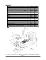
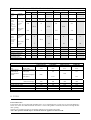
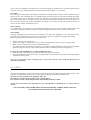
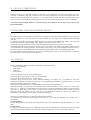
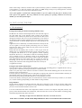
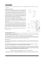
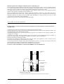
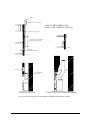
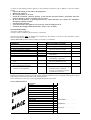
INSTALLATION & OPERATING INSTRUCTIONS
The
Stratford Multifuel
Sf & Si Stoves
Stratford Sf 50 Convector
PLEASE RETAIN THESE INSTRUCTIONS FOR FUTURE REFERENCE
Congratulations on your choice of an Aarrow Stove.
More than 20 years experience has been put into the
development of our Stratford Multifuel to ensure ultimate
performance and years of trouble free enjoyment.
Every detail on the fire has been carefully engineered and
designed which is why we are so confident in the reliability of
our product.
Should you have any questions about our Stratford Stoves that
are not covered in this manual, please contact the Aarrow dealer
in your area, or call our Technical support department on
01308 427234
Flaming Good Fires!
© COPYRIGHT July 2001
Aarrow Fires Ltd
This booklet has copyright & may not be
copied in whole or part or be used for any
purpose other than that for which it is
supplied without express written consent
from Aarrow fires Ltd.
2
The
Stratford Sf & Si
Installation and Operating
Instructions
Contents
Operating Instructions
1
2
3
4
5
6
7
8
9
10
11
12
13
14
15
16
Introduction - The Principle of the Fire
Checklist
A - Stratford Sf
B - Stratford Si
Fire Bed
Firebrick Lining for Sf only
Throat Inspection
The Air System
A - Interlock
B - Multi-Purpose Operating Tool
Glass/Trim
Door Adjustments
Spare Parts List
A - Stratford Sf
B - Stratford Si
Accessories
Fuels
Lighting the Fire
Overnight burning
Ash removal
Cleaning
Safety
5
6
7
8
9
10
12
13
14
16
17
18
19
20
21
22
Installation Instructions
17
18
19
20
21
22
23
24
25
26
27
28
29
30
General
Handling
Hearth
Combustible Materials
Air For Combustion
Builders Opening/Chimney Breast
Chimney
Installing the Fire
A - Stratford Sf
B - Stratford Si
Flues & Chimneys
Water Connections
Final Check
Guarantee
Customer Registration
Service Record
3
23
23
23
23
24
24
24
25
27
30
31
32
32
33
WARNING
To All Solid Fuel Users
PETROLEUM COKE
SOME OF WHOSE BRAND NAMES ARE
"CALCO", "PETROCOKE" OR "WONDERCO"
MUST NOT BE BURNED IN THIS APPLIANCE
TO USE THIS FUEL WILL INVALIDATE THE APPLIANCE
WARRANTY
IF IN DOUBT CONTACT THE SOLID FUEL ASSOCIATION
TELEPHONE FREEPHONE 0800 600000
THE USE OF SPARE PARTS OTHER THAN THOSE
SUPPLIED BY AARROW FIRES LTD WILL INVALIDATE
THE APPPLIANCE GUARANTEE.
4
Operating Instructions For
The Stratford Multifuel Sf & Si.
1. INTRODUCTION - THE PRINCIPLE OF THE FIRE
Your Aarrow Fire is built to the highest standard of craftsmanship using the best materials and the most modern
equipment available. It is a highly efficient and sophisticated piece of machinery and when properly installed and
operated it should provide a lifetime of heating satisfaction.
Safety is the most important consideration when installing your fire. If not properly installed and operated a
house fire may result. You should check your local Building Regulations and conform to all relevant fire safety
standards.
Aarrow Fires produce a variety of appliances that range from the traditional in appearance to the ultra modern,
all bristling with "High tech" features.
Model types include simple room heaters, convectors, integral boiler models and inset units. Your Aarrow fire is
constructed from twin wall steel strengthened where necessary. Cast iron is used where appropriate for long life.
All fire doors are fitted with special high temperature ceramic glass panels through which the fire can be viewed.
All units are fitted with a cast iron grate to give full multifuel facility and positive de-ashing.
All models except integral boiler models and insets are lined with heat reflective panels which ensure complete
combustion and provide a good heat store to even out fluctuations in burning.
An internal throat plate produces turbulence to encourage secondary combustion and directs the flue gas around
the whole upper firebox before allowing it to escape to the chimney.
The primary air for burning enters the ash pit chamber beneath the grate, controlled by the air inlet mechanism or
by the thermostatically controlled damper where fitted.
The provision of two inlets gives a wide range of primary air/secondary air, under draught/over draught
combinations. The optimum settings will only be established by experience in the firing the appliance, and will
depend on type of fuel, the position of the appliance in the house, condition of chimney etc.
Aarrow fires are also fitted with an "air wash" so called because it provides a curtain of high speed preheated air
in front of the glass to help keep it clean and to provide secondary air/over draught.
Solid Fuel.
To burn solid fuel efficiently the main source of combustion air should be under draught entering the ash pit
chamber. The air wash can be opened a little to allow sufficient air to keep the glass clean and provide secondary
air for afterburn.
Wood
Wood burns very efficiently on a bed of its own ash and an over draught. It will also burn successfully with an
under draught, and on appliances fitted with a thermostat this should be the main source of combustion air in
order for the thermostatic control to be effective.
Mixed Solid Fuel and Wood
When burning mixed fuels the grate should be set to the coal burning position with combustion air entering
equally from above the fire through the air wash, and below through the ash pit door.
Diagrams and notes on the features of the different types of fires are set out in the sections following this one.
5
2. CHECK LIST
Inside the appliance you should find the following.
Grate Bars
Fire Bed Surround
Refractory Lining
230x197
Refractory lining
230x138
Refractory lining
230x115
Rear Brick Locking
Channel
Fuel Retainers
Throat Plate
Flue Spigot
Hot Plate
Ash Pan
Operating Tool
Thermostat*
Instructions
Stratford Sf
30
Stratford Sf
50
Stratford Sf
70
Stratford Sf
90
Stratford Si
40
Stratford Si
60
Conv.
Boil.
Conv.
Boil.
Conv.
Boil.
Conv.
Boil.
Conv.
Boil.
Conv.
Boil.
7
7
7
9
9
7
11
11
9
11
11
11
7
7
3
11
11
4
3
1
1(6'')
1(6'')
1
1
1
1
3
1
3
1
3
1
3
1
1
1
1*
1
1
1
1*
1
1
1
1*
1
1
1
1*
1
4
4
3
5
4
2
1
1
1
3
1
1(5'')
1(5'')
1
1
3
3
3
3
1
1
1
1
1(5'') 1(5'') 1(5'') 1(6'')
1(5'') 1(5'') 1(5'') 1(6'')
1
1
1
1
1
1
1
1
1
1
1
1
1
1
1
* Only the knob, the thermostat is already fitted to the stove
3
1
1(6'')
1(6'')
1
1
1
1
3
1
1(6'')
1(6'')
1
1
1
The model and Serial No. of your fire can be found stamped into the casing, centrally just below the bottom edge
of the fire door aperture.
A - Stratford Freestanding - Sf
Top flue
Hot plate
Rear flue
Air wash control
Fire door
Firebrick
Fuel retainers
MULTIFUEL
GRATE
CONTROL
COAL
WOOD
Multifuel grate
Ashpit door
Ashpan
Operating tool
B - Stratford Inset - Si
Boiler unit
Flue outlet socket
Air wash control
Flow tapping
Sensor phial
Fire door
Fuel retainers
Return tapping
Multifuel
Grate
Control
Thermostat
control unit
Multifuel grate
Front trim
Ashpan
Ashpit door
Thermostat
damper plate
Operating tool
6
3. FIRE BED
Grate
The grates in the Stratford Sf & Si Multifuel units comprise a series of reciprocating cast iron bars seated on a
pivoted "comb". All bars in the grate are identical, but every other bar is turned through 180 degrees, with the
ends of the bars marked "H" sitting on the high sections of the comb, and the ends marked "L" sitting on the low
sections.
Assembling the Grate (Fig.1)
To assemble the grate, fit bars to low sections of the comb first, inserting end market "H" into rear channel with
groove on underside of bar located on upstand tab, and then lowering end marked "L" onto the low section of the
comb. The upper bar is fitted in a similar manner, but with the end marked "L" inserted in the rear channel, and
the end marked "H" seated on the high section of the comb.
"HIGH" GRATE BAR
"LOW" GRATE BAR
COMB
COMB EXTENSION SHAFT
FITTING BARS TO COMB
ASSEMBLED GRATE
Figure 1
Grate bar Replacement
After extended use it may be necessary to replace some of the grate bars. Periodic inspection of the bars is
recommended and the removal of any nails or wire that may be present after burning wood. All the grate bars in
each appliance are identical and can easily be lifted out after removal of the fuel retainers.
Remove damaged grate bars and replace with casting of the same type, fitting as per instruction above. (Check
Identification letters on the casting when reordering).
Riddle Lever for Sf only (Fig 2a)
The riddle lever gives effective de-ashing, and also allows the grate to be set in the coal burning or wood burning
position, as indicated on the right hand side of the appliance.
For Si use the operating tool provided. Rotating the end shaft of the comb with the operating tool gives effective
de-ashing, and also allows the grate to be set in the coal or wood burning position, as indicated on the right hand
side of the appliance (Fig 2b).
COAL
COAL
GRATE SETTING
INDICATORS
COMB EXTENSION
OPERATING TOOL
WOOD
WOOD
Figure 2a
Figure 2b
7
4. REFRACTORY LINING FOR Sf CONVECTOR MODELS ONLY
Warning: Refractory linings are very fragile, handle with extreme care.
Stratford Sf Multifuel Convectors are lined with reflective panels, consisting of a combination of rectangular
linings, which sit on the rear ledge, and side linings which sit on the landings. A throat plate is sited above the
grate, so shaped that it rests on steel guides and between the side linings.
If the refractory linings have not been fitted to your appliance prior to despatch, they should be fitted as follows:
Stratford Sf30 & Sf50 (see Fig 3 & 4)
SF50 CONVECTOR
SF30 CONVECTOR
Figure 3
•
•
•
•
•
Figure 4
Remove front fuel retainer bars.
Set the two linings on the side ledges on either side of the firebox.
Set the rectangular linings on the upper surface of the grate bar channel at the rear of the firebox.
Fit the throat plate with the tab at the front marked "Throat plate" pointing down, with the projecting lugs on
the sides of the throat plate resting on the top of the baffle landings and the bend at the back resting against
the rear refractory lining
Replace the front fuel retainer bars.
Note: Neither the rear linings nor the side linings are "handed" and both faces are suitable for direct contact
with the fire.
Stratford Sf70 & Sf90 (see Fig 5)
SM70 Convector / SM90 Convector
Figure 5
8
•
•
•
•
•
•
Remove front fuel retainer bars.
Set the four linings on the side ledges on either side of the firebox. See Fig 5.
Set the three 197mm x 230mm rectangular linings on the upper surface of the grate bar channel at the rear of
the firebox.
To keep the back linings in position, locate the stainless steel locking channel centred on the top edge of three
rear linings.
Fit the throat plate with the tab at the front marked "Throat plate" pointing down, with the projecting lugs on
the sides of the throat plate resting on the top of the steel guides, and the bend at the back resting against the
rear firebox lining.
Replace the front fuel retainer bars.
Note: Neither the rear linings nor the side linings are handed and both faces are suitable for direct contact
with the fire.
5. THROAT PLATE INSPECTION
The throat plate for all fires type consists of a profiled steel plate with "drop down" facility for inspection
purposes.
To "drop" the throat plate (Fig 6), engage the operating tool behind the downstand tab marked "throat plate" and
pull the plate frontward until its forward lugs drop into the cut-away at the front of the side panel. Check the
upper surface for soot, ash build-up, etc. Reverse the procedure to return the throat plate to the working position.
Warning: If the fire is operated with the throat plate in the down position the air wash will not operate
effectively.
THROAT PLATE GUIDE
THROAT PLATE
OPERATING TOOL
Figure 6
Throat Plate position for Si only
9
6. THE AIR SYSTEM
Flue Outlet/Hot Plate only for Sf
The flue outlet is packed together with the firebrick lining and multi-purpose tool, inside the appliance. The hot
plate comes fitted on the top of the fire.
To fit flue outlet:
• Select the desired position (top or rear outlet)
• Smear a very thin layer of suitable sealant or fine adhesive fire cement around the edge of the flue cut-out in
the appliance
• Fit outlet and lock into place by rotating anti-clockwise
• Similarly fit the hot plate to the unused position
• Clean off surplus sealant
Air Inlet Controls
Stratford Multifuel Sf & Si fires have two air inlets.
1. The air wash system (so called because its pre-heated high speed air washes across the inner face of the door
glass, keeping it clear), which provides over draught, and
2. The primary air inlet providing under draught to the base of the fire chamber.
Primary Air
On all Multifuel units primary air enters the appliance through the gap between the body and the ash pit door.
The width of the gap is controlled by rotating the knob (if hot, with the operating tool) anti-clockwise to increase
the air inlet, clockwise to reduce the air inlet, or to seal the ash door completely.
On units fitted with a thermostat, partial opening of the ash door will over-ride and negate the thermostatic
control.
Note: Opening or part opening of the ash door is controlled by the "interlock" device located in the front of
the unit (refer to INTERLOCK section on page 9)
Thermostats
Stratford Sf Integral Boiler units have a thermostatically controlled rear air inlet. The damper plate at the back
of the appliance regulates the amount of under draught entering, depending on the setting of the thermostat
control knob (located at the bottom rear of the right hand side of the unit) and the temperature of the water
transmitted through the sensor phial in the water jacket.
Stratford Si units have a thermostatically controlled side air inlet. The damper plate at the side of the appliance
regulates the amount of under draught entering, depending on the setting of the thermostat control knob (located
at the top of the left hand side of the unit) and the temperature of the water/air transmitted through the sensor
phial in the water/air jacket.
Stratford Sf & Si: with the ash door fully shut, the settings range from 0 (fully anti-clockwise) a shut-off setting
at which the damper will shut off the under draught completely, causing the fire to die down and in time go out,
to 8 (fully clockwise) the highest setting at which the appliance will burn fiercely and produce very high outputs.
Note: The area around the thermostat, both inside at the back of the firebox and externally, must be cleared
of ash and other debris regularly.
For setting instructions refer to "Checking Thermostat" in the installation instructions.
On units fitted with a thermostat, partial opening of the ash door will over-ride and negate the thermostatic
control.
Air Wash
The air wash has an internal sliding plate with slots, housed in a cover plate, and is located above the fire door.
Sliding the control shaft to the right as far as will go achieves the fully open position. Sliding it the left will shut
off the air inlet slots. The operating tool should be used to tap the control shaft to the desire setting. Even when
all the slots are completely shut a "bleed" of secondary air will be maintained ensuring that inflammable gases
are burnt off.
10
Disassemble Air Wash (see fig. 7)
The air wash may be disassembled for cleaning or adjustment to achieve this the following procedure should be
followed when the fire is cold and unlit.
•
Support Air Wash cover with one hand
•
Move cover up by smartly tapping the bottom with a hammer.
•
Remove assembly from appliance.
•
Clean and/or adjust.
•
Refit using reverse procedure.
FULLY CLOSED
POSITION
FULLY OPEN
POSITION
AIRWASH
HAMMER
Figure 7
A - Interlock
Stratford Sf & Si fires are fitted with an "interlock" system. A situation where the fire door is closed and the ash
door is open may lead to serious overfiring which could damage the appliance. Correct use of the doors and
interlock system will ensure that this does not happen.
Operation is as follows:
A pivoted lug prevents closure of the fire door, unless the ash door has been shut first.
When the fire door is shut the ash door knob can be turned anti-clockwise by up to 95 degrees creating a variable
gap between the top of the ash door and the body, through which primary combustion air can enter the appliance.
Note: In order to turn the ash door knob sufficiently for the catch to release and permit the ash door to be
opened fully THE FIRE DOOR MUST BE OPENED FIRST.
SUMMARY: Sequence of operations
•
Close ash door.
•
Close fire door.
•
Set primary air gap (if required).
•
Open fire door.
•
Open ash door.
B - Multi-purpose operating tool
Your Aarrow fire comes with a multi-purpose operating tool which is used for the emptying of the ash pan and
opening the ash pit door (see fig.8 overleaf). For the Si only it is also used for de-ashing the appliance and for
setting the grate to the wood or coal positions as marked on the side of the appliance.
11
DOOR KNOB
ASHPPAN
OPERATING TOOL
OPERATING TOOL
Ash pit door
Figure 8
7. GLASS/TRIM
A gilt trim fitted around firedoor glass comes as standard. It clips on to the small lugs at the top and bottom of
the aperture in the cast iron firedoor, as a "spring fit". When fitted, the trim locks the glass retaining clips in
position. (see fig 9).
If necessary the glass can be removed as follows:
• Remove the gilt trim by pressing on the curved edge at the top until the trim can be disengaged from the lugs.
• Slide the two glass retainer clips on one side only inwards towards the centre of the door as far as they will
go.
• Pull this side of the glass away from the door casting, easing the tags on the glass retaining clips past the
edge of the aperture in the door casting.
• Remove the glass completely and store glass retaining clips and white gasket (if sound) safely for re-use.
• Follow this procedure in reverse to fit replacement door glass or gasket.
The fire door should be lifted off the hinges so that the above operations can be carried out on a work
bench or similar surface.
GLASS
GLASS CLIP
GASKET
FIRE DOOR
Figure 9
12
8. DOOR ADJUSTMENTS
The catch can be adjusted by sharply tapping the catch on the inside of the door as shown in Fig 10.
Once the appliance has been under fire for a period of time the fire door may appear to have moved out of
alignment with relation to the door aperture or catch on the door interlock mechanism. This is quite normal and
due to the settling of the casing.
The fire door can be re-aligned by the user as follows:
• When the appliance is cold, open the fire door so that it is at a right angle to the front face of the fire.
• Lift the fire door up off the hinges.
• Gently tap the two hinge pins in a direction to compensate for the misalignment.
• Refit the door and check to ensure it now sits square to the body; if not repeat above steps.
Raising the door as follows:
• When the appliance is cold, open the fire door so that it is at a right angle to the front.
• Lift the fire door up off the hinges.
• Drop one washer (supplied) on the top and bottom hinge pin.
• Refit the door and check to ensure door is free of the interlock. If not remove and repeat fitting second
washer.
HAMMER
DOOR CATCH
KOOLER TO
TOUCH
HANDLE
Figure 10
13
9. SPARE PARTS LIST
A - Stratford Sf
Description
Item
Sf30
Ashpit Door, complete with Handle & Seal
Ashpit Door Handle
Decorative Trim (Door Surround)
Gold
Black
Fire Door, Complete with handle, Glass, Gaskets, Clips &
Seal
Hinge Kit, Comprises 2 Hinges, 4 Shims & Fixings (1 set)
Glass Replacement Kit, Complete with Gaskets & Clips
(Not Glass)
Glass Kit, Complete with Glass, Gasket & Clips
Fire Door Handle complete
Ash pan
Riddling Lever & Riddle Assembly
Grate Bar
Fire Bed Surround
Grate Bar landing with fixings
Convector Models
Boiler Models
Fuel Retainer
Throat Plate (Baffle)
Air wash Inner & Outer
5'' Flue Outlet
6'' Flue Outlet
5'' Hot Plate
6'' Hot Plate
Thermostat Assembly, Includes Damper, Fixing & Control
Knob
Thermostat Control Knob
Thermostat Damper Plate
Operating Tool
Door Rope Kit (Not Shown), Complete with Glue & Shims
Comb
1
2
3
Part No
Sf50
Sf70
Sf90
4
AFS045
AFS041
AFS095
AFS095A
AFS200
AFS046
AFS041
AFS096
AFS096A
AFS201
AFS049
AFS041
AFS097
AFS097A
AFS202
AFS049
AFS041
AFS097
AFS097A
AFS202
5
6
AFS047
AFS089
AFS047
AFS091
AFS047
AFS093
AFS047
AFS093
7
8
9
10
11
12
13
AFS088
AFS203
AFS050
AFS164
AFS001
AFS007
AFS074
AFS075
AFS152
AFS030
AFS025
AFS009
AFS090
AFS203
AFS051
AFS165
AFS001
AFS007
AFS076
AFS077
AFS153
AFS031
AFS025
AFS009
AFS092
AFS203
AFS052
AFS166
AFS002
AFS007
AFS082
AFS083
AFS154
AFS034
AFS025
AFS092
AFS203
AFS053
AFS167
AFS003
AFS007
AFS084
AFS085
AFS154
AFS035
AFS025
AFS011
AFS011
AFS010
AFS010
AFS020
AFS020
AFS012
AFS020
AFS012
AFS020
AFS022
AFS021
AFS008
AFS048
AFS168
AFS022
AFS021
AFS008
AFS048
AFS170
AFS022
AFS021
AFS008
AFS048
AFS172
AFS022
AFS021
AFS008
AFS048
AFS173
14
15
16
17
17
18
18
19
20
21
22
23
24
Use of spare parts other than those supplied by Aarrow Fires Ltd will invalidate the appliance
guarantee.
14
B -Stratford Si
Description
Item
Part No
Si40
Ashpit Door, complete with Handle & Seal
Ashpit Door Handle
Decorative Trim (Door Surround)
Gold
Black
Fire Door, Complete with handle, Glass, Gaskets, Clips & Seal
Hinge Kit, Comprises 2 Hinges, 4 Shims & Fixings (1 set)
Glass Replacement Kit, Complete with Gaskets & Clips (Not
Glass)
Glass Kit, Complete with Glass, Gasket & Clips
Fire Door Handle complete
Ash pan
Comb & Comb Extension
Grate Bar
Fire Bed Surround
Grate Bar landing with fixings
Convector Models
Boiler Models
Fuel Retainer
Throat Plate (Baffle)
Air wash Inner & Outer
Thermostat Assembly, Includes Damper, Fixing & Control Knob
Thermostat Control Knob
Thermostat Damper Plate
Operating Tool
Door Rope Kit (Not Shown), Complete with Glue & Shims
Side trim, 1 pair
1
2
3
4
5
6
7
8
9
10
11
12
13
14
15
16
19
20
21
22
23
24
Si60
AFS045
AFS041
AFS095
AFS095A
AFS200
AFS047
AFS089
AFS046
AFS041
AFS096
AFS096A
AFS201
AFS047
AFS091
AFS088
AFS203
AFS054
AFS062
AFS003
AFS007
AFS078
AFS079
AFS152
AFS032
AFS025
AFS023
AFS022
AFS021
AFS008
AFS048
AFS026A
AFS090
AFS203
AFS055
AFS065
AFS003
AFS007
AFS080
AFS081
AFS153
AFS033
AFS025
AFS023
AFS022
AFS021
AFS008
AFS048
AFS027A
Use of spare parts other than those supplied by Aarrow Fires Ltd will invalidate the appliance
guarantee.
15
10. ACCESSORIES
Stands
Elegant stands are available for the Stratford Sf only. These increase the height of the appliance and rear flue
outlet by approximately 125mm (6''). Check current brochure for details.
Traceries
For added decorative effect, beautiful Door Traceries (Arches, Dawn & Sunburst) are available for the complete
Stratford fires range.
Paint
Matching aerosol paint to tone in any connecting flues, pipes or surrounding metalwork.
Interchangeable Canopy
Traditional canopy (Low) is available for the Stratford Si only. It is easy to fit and can always be added
afterward.
Add in Boilers (see fig 11)
A "slab" type add-in-boiler is available for the Stratford Sf only, which occupies the position of the rear firebox
liner panel.
Stratford Sf convector units can be fitted with "slab" type boilers only, not "cantilever" type.
Fitting:
Remove the fuel retainers, rear firebox liner panels and throat plate.
Knock out the 2 blanking discs corresponding to the terminals on the boiler at the rear of the fire.
Introduce the boiler to the appliance through the main fire door and locate the terminal pipes through the
back plate holes and seal around boiler terminals with fire cement.
• Engage locking nuts to the thread of the terminals and tighten to secure the boiler in position, ready for
connection to flow and return pipes.
• Replace, throat plate and fuel retainers.
•
•
•
Note: On boilers the terminal which is approximately flush with the edge of the boiler and marked "TOP"
must be fitted uppermost, to prevent "Kettling".
For details of the outputs and sizes for your particular model please see Chart overleaf.
Figure 11
16
TECHNICAL DATA
Room
Heater
only
Room
Heater
with
domestic
hot
water with
optional
add in
boiler
Room
Heater
with builtin wrap
around
boiler
Min/Max
output (kw)
Max output
to room
(kw)
Max output
to water
(kw)
THE STRATFORD Sf RANGE
Stratford Sf 30
Stratford Sf 50
Stratford Sf 70
Conv. Boiler
Conv.
Boiler
Conv.
Boiler
2-8
N/A
N/A
5 - 26
N/A
Boiler
Boiler
type 70/90
type 70/90
5.4
8
16
23
N/A
2.6
N/A
N/A
3
3.6
2
2.5
3.6
4
N/A
N/A
N/A
7
11
6
N/A
16
22
590
560
370
445
139
590
560
370
445
139
630
665
375
500
135
630
665
375
500
135
705
750
450
555
172
705
750
450
555
172
705
750
515
555
172
705
750
515
555
172
127(5'')
127(5'')
127(5'')
127(5'')
152(6'')
152(6'')
152(6'')
152(6'')
TECHNICAL DATA
Room Heater
only
Room Heater
with built-in
wrap around
boiler
4 - 19
Boiler
type 50
Max output
to water
(kw)
Depth from back to
centre flue (mm)
Flue Diameter (mm)
N/A
Boiler
type 30
Max output
to room
(kw)
Height (mm)
Width (mm)
Depth (mm)
Height to Centre(mm)
3 - 11
Stratford Sf 90
Conv.
Boiler
Min/Max
output (kW)
Maximum output to
room (kW)
THE STRATFORD Si RANGE
Si 40 Convector
Si 40 Boiler
Si 60 Convector
Si 60 Boiler
2-10
N/A
4-15
N/A
2.0
3.0
N/A
Maximum output to
water (kW)
Height of front (mm)
with Low Canopy
Width of front (mm)
Depth of front (mm)
Height of inset box
Depth of inset box (mm)
Flue Diameter (mm)
N/A
12.0
575
706
590
140
545
360
127 (5'')
575
706
590
140
545
360
127 (5'')
16.5
620
786
705
140
585
360
127 (5'')
620
786
705
140
585
360
127 (5'')
11. FUELS
Fuel retainer bars
Fuel retainer bars are supplied with multifuel fires. For wood burning the top bar may be removed affording a
better view of the fire. Slide and lift the bar until it is clear of the guides at each side, and remove through the fire
door opening.
The bars are symmetrical and of even lengths making incorrect fitting impossible.
Note: This operation should only be carried out when the appliance is unlit and cold.
17
Recommended fuels are as fellows:
The Hetas Ltd, "Three Tick" appliance approval only covers the use of the following fuels in this appliance;
Phurnacite, Phurnacite Plus, Centurion, Maxibrite, Extracite, Pureheat, Blazebrite, Taybrite, Sunbrite
(Doubles/Singles), Anthracite and Welsh Dry Steam Coal (Large/Small Nuts). Approval does not cover the use of
other fuels either alone or mixed with the suitable fuels listed above, nor does it cover instructions for the use of
other fuels.
DO NOT USE SOFT COAL.
Do not use smaller sizes than Stovesse, e.g. Beans, Peas, Grains.
Do not use petroleum based solid products such as Calco or Petrocoke.
To do so will invalidate the appliance guarantee.
Wood
Any type of wood is suitable provided it is well seasoned and has been a moisture content below 20%. This
usually implies that the timber has been stored at lest nine months in the case of softwoods, and at least eighteen
month in the case of hardwood. In cases where the moisture content is above 20%, tests show that better results
are achieved by mixing the fuels 50% wood and 50% solid fuel, although some discoloration of the glass is
likely. The coal burning setting should be used when mixed fuels are burnt. We recommend that for general
burning, wood should be split into logs of no more than 130mm (5'') diameter.
Larger logs can be used for overnight burning
Warning: Green wood must not be used, as this will greatly contribute to the creation of tar and creosote,
which may, in extreme cases, run down the chimney in liquid form. This will seriously damage both the
chimney and appliance.
Note: If you have sticky tar inside the appliance or chimney your wood is green.
Peat
Peat can be used in turf or briquette form, but again the moisture content must be low. Treat in a similar fashion
to wood, however it does produce a lot of ash.
Paper
Household refuse will burn successfully. Burn dry waste only or chimney damage will occur. DEFINITELY NO
PLASTICS.
Coal
Household coal produces a large amount of ash and smoke. If used the appliance and the chimney will require
frequent cleaning. Therefore soft house coal is not recommended.
12. LIGHTING THE FIRE
Pre-lighting checks
Check with your installer that:
• All building work is complete.
• The chimney is sound and has been swept and is free from obstruction.
2
• Adequate provision for combustion air has been made, i.e. a permanent vent of at least 550mm per kW of
rated output above 5 kW, is fitted in the room in which the appliance is installed.
• That Building Regulations and any local by-laws have been followed during installation (see installation
instructions).
• All firebox liner panels are in place.
• That the grate is correctly fitted and moves freely.
• That the ash pan is fitted.
• For all boiler models: that the system is full of water and vented, and precautions have been taken to prevent
corrosion (see installation instructions).
• There is sufficient draw in the chimney. When the chimney is warm the draught should be between 1 - 2mm
water gauge (0.1 - 0.2mbar).
ENSURE THAT YOU HAVE READ AND UNDERSTOOD THESE INSTRUCTIONS BEFORE
LIGHTING THE FIRE.
18
Lighting the fire
Solid fuel burning
• On multifuel fires with variable grate setting facility set the grate to the "coal" burning position.
• Ensure that ash pan is in position and the fire door closed.
• Set the air wash to one quarter open position.
• Set the primary inlet to the fully open position (or the thermostat control knob to setting 8).
• Light in the normal manner with paper and kindling, or use a fire lighter.
• If using a gas poker be sure to remove it immediately the fire has started.
• When the fire is well alight regulate the burning rate by adjusting the setting on the primary air inlet control
or the thermostat.
• The air wash can be opened sufficiently to keep the door glass clean.
Wood burning
• Set the grate to the "Wood" burning position.
• Set air wash to fully open position
• Proceed as for solid fuel but note the fire will burn up and become established more quickly.
Mixed Fuels
• As per coal but allow additional secondary air
On fires fitted with an air wash and a manually controlled primary air inlet the air inlet can be closed, and
burning regulated by means of the air wash above the door. On models fitted with Thermostatic control the
amount of air entering the ash pit chamber can be reduced, and supplemented with over draught via the air wash.
Warning Boiler Models: Do not light the fire if it is suspected that any part of the water system is frozen.
Note: The high temperature paint acquires durability by being "cured" during the initial firings of the
appliance. During this process the appliance will give off fumes which are non-toxic, but which certain
persons may find have an unpleasant or irritant effect. Ensure that the area is well ventilated during this time.
Alternatively carry out initial firings in an exterior environment prior to installation.
13. OVERNIGHT BURNING
The appliance will burn easily overnight provided:
• Sufficient fuel is placed in the firebox.
• The controls are set correctly.
• Excess draught is not present in the chimney.
Solid Fuel
Manufactured smokeless fuel:
• Start with a fire that is burning well. De-ash the fire.
• Empty the ash pan if necessary.
• Place as much fuel in the appliance as possible without the stability of the fire being affected.
• Set the air wash on a low setting.
• Set the bottom inlet control to a minimum, or on models with thermostat set the control knob to a low setting.
In the morning
• Run with air inlet control fully open for about ten minutes.
• De-ash lightly. Re-fuel and empty the ash pan.
Anthracite
Anthracite is more difficult to keep in for long periods. Consequently more care in setting the controls and some
familiarisation is necessary when burning anthracite. Use the smallest size fuel (Stovesse or Small Nuts).
Proceed as for manufactured smokeless fuel.
Leave air inlet control open about a quarter or less (Thermostat setting 3).
19
In the morning
Open air control fully until the embers begin to glow brightly.
Lightly de-ash.
Place smaller pieces of fuel on the fire up to the top of the fuel retainer bars.
When the fire is well established de-ash and empty the ash pan.
•
•
•
•
Note: The exact setting of the controls will vary with chimney conditions etc. If the fire goes out with unburnt
fuel left in the firebox, increase the air opening slightly, and vice versa.
Wood
Fill the firebox as much as possible with pieces of wood cut to the width of the firebox.
Stack the wood so that few air gaps exist between the pieces of wood.
Close the door.
Close the lower air inlet to a setting depending upon atmosphere conditions (on a windy night it should be
almost completely closed whereas on a still night a more open setting will probably be required to prevent the
fire going out) set the air wash to about one half open subject to the guidance on atmosphere conditions.
•
•
•
•
Note: The setting of the controls will also be affected by chimney conditions etc. If the fire goes out with
unburnt fuel left in the firebox, increase the air opening slightly, and vice versa.
In the morning
• Open the air control fully until embers begin to glow brightly and place pieces of fuel on the fire until it is
well established.
Warning: When wood is burnt slowly in a closed appliance it produces moisture and tar, which will create
condensation and deposits in the chimney. This effect can be minimised by burning hard for a short
period, about 20 minutes, twice a day. It is usually convenient to do this morning and night.
Note: To avoid chimney problems your fire should not be burnt slowly for longer than 12 hours without a
period of fast burning.
Warning: Properly installed, operated and maintained this appliance will not emit fumes into the
dwelling. Occasional fumes from the de-ashing and re-fuelling may occur. However, persistent fume
emission is potentially dangerous and must not be tolerated.
If fume emission does persist, the following immediate actions should be taken.
• Open doors and windows to ventilate room
• Let the fire out or eject and safely dispose of fuel from the appliance.
• Check for flue or chimney blockage, and clean if required.
• Do not attempt to re-light the fire until the cause of the fume emission has been identified and corrected. If
necessary seek expert advice.
14. ASH REMOVAL
De-Ashing (Solid Fuel)
It is necessary to maintain an ash layer on the upper surface of the grate bars, in order to protect them so deashing should cease as soon as the first red embers drop into the ash pan. Further de-ashing will cause heat buildup under the grate, which will considerably shorten its life. This operation should be carried out with the doors
closed to prevent dust escaping into the room.
For Stratford Sf
•
Move up and down vigorously the riddling lever (Ash will fall into the ash pan beneath the grate).
•
When de-ashing is complete re-set grate to previous position.
•
Empty ash pan
Note: Do not force the riddling lever.
20
For Stratford Si
Engage the operating tool on the comb extention.
Move up and down vigorously the riddling lever (Ash will fall into the ash pan beneath the grate).
When de-ashing is complete re-set grate to previous position.
Empty ash pan
•
•
•
•
The ash pan should be emptied at least twice a day or when the level of ash reaches the top of the pan. On no
account should the ash be allowed to build up to touch the grate as this will greatly shorten its life.
To empty the ash pan
Open the fire door; open the ash door. Fit the fork end of the operating tool into the ash pan and remove from the
ash pit chamber. The ash pan on some large appliances has a pivoted "strap" handle to make carrying easier. This
handle can get very hot and an oven glove or similar should be used.
Warning: The ash can be very hot. Empty only to a metal container. Even if the ash appears cold, red-hot
pieces of ash may be concealed and could easily start a fire or cause an injury. Replace the ash pan and
close ash door. Close the fire down.
Over-firing
Do not over fire your appliance. Using flammable liquids or too much wood or firing the stove at maximum for
prolonged periods may result in over-firing. If the chimney connector or casing glows red it is being over-fired.
If this occurs immediately close all air inlets to the appliance to reduce the air supply to the fire. Should a
chimney fire occur immediately close the appliance down. Get everyone out of the house and call the fire
brigade. A chimney fire may cause a structural damage of the chimney. Do not use the appliance until the
chimney and connector have been inspected and any damaged parts have been repaired or replaced. A chimney
sweep can perform this inspection.
Clinker
The formation of clinker suggests that the unit is being over-fired. Any clinker forming on the grate should be
removed when cold.
15. CLEANING
Important
Under some circumstances soot can quickly build up on the throat plate and adjacent areas. The throat plate
should be removed and checked monthly, and any soot stripped off. Similarly, clean the upper surface of the
firebox.
Refer to page 7 for instructions on throat plate inspection.
It is important that your fire is regularly serviced in accordance with the manufacturers instructions at least
annually by a qualified person and should consist of the following.
Annual Maintenance
Remove the firebricks lining (if fitted), throat plate, grate bars and ash pan. Also inspect all gasketing on doors
glass etc., and re-order any items that may need replacing, from your Aarrow dealer. With a wire brush clean
inside the appliance paying particular attention to the small inlet holes of the air wash on the inside, above the
fire door and to the door interlock ensuring free movement of the mechanism exists. Sweep the chimney and
confirm that it is sound. Examine all joints in the flue pipe etc., and re-seal if necessary. Reassemble and leave
with the air inlet and air wash control about half way open. This will allow a free flow of air through the
appliance thus preventing moisture and condensation from building up inside the fire and chimney.
Chimney Sweeping
Sweeping should be carried out with a wire-centred sweep's brush fitted with a guide wheel. As with all
multifuel appliances regular sweeping of the flue is essential to avoid the danger of blockage and the escape of
poisonous fumes.
Any existing chimney should be swept prior to installation of the appliance, and swept again a second time
within one month of regular use after installation. Sweep the whole flue way, including the outlet, at least twice
per burning season. It is important that the flue ways, flue pipe and chimney be cleaned prior to lighting the fire
after a prolonged shut-down period.
Stop using the appliance if you smell fumes or see smoke escaping.
21
Aarrow fires are designed so that the flue can be swept through the appliance once the throat plate has been
removed. Access for cleaning should also be incorporated in the chimney (i.e. a soot door).
Door Glass
The door glass should remain clear during normal daytime burning. However under certain conditions-such as
burning at a low rate with damp fuel, or overnight burning of wood, the glass may become somewhat blackened.
To remedy this, operate the appliance at a fast rate. Alternatively open the door and clean the inside face of the
glass with a damp cloth or with glass cleaner (available from fire stockists) taking care not to burn fingers. A
piece of cloth moistened with vinegar and dipped in wood ash - not coal ash - will provide a good soft scourer to
remove the soot without scratching the glass.
Other Surfaces
The outside finish of the appliance is a durable high temperature paint. It is best cleaned by brushing down with
a clean shoe brush. Do not allow moisture to remain on the appliance whilst cold or surface rust may form.
Outer Finish
The high temperature paint should not require attention for some time, depending on use. The hotter the fire
burns the sooner repainting will be necessary. Aerosol tins of paint are available for complete refurbishing.
Before repainting make sure that the fire is out and is cold.
•
•
•
•
Remove the door glass and gilt trim.
Lightly wire brush, or rub with wire wool, the body of the appliance to remove any loose paint powder.
Mask or remove items such as brasswork, thermostat knobs
Any adjacent brickwork, mantelpiece, hearth, etc., should be carefully masked for quite a distance around the
appliance. (this precaution is to prevent discoloration of the surrounding brickwork, wallpaper etc.).
Re-spray in a well-ventilated area - avoid breathing the vapour.
When the paint is dry refit door glass and any other parts previously removed.
Leave the appliance for eight hours before re-lighting. Burn slowly for the first four hours, then build up heat
gradually to cure the paint.
•
•
Note: Use only genuine Aarrow touch-up spray as some paints interact. This could ruin the finish and
invalidate the guarantee.
16. SAFETY
A fireguard conforming to BS 6539 should be used in the presence of children and old/or infirm people. If the
appliance is used with the fire door open, a spark guard conforming to BS 3248 should be fitted.
Do not use aerosol sprays near the appliance under fire
Do not fit an extractor fan in the same room as the appliance.
Fire cement is caustic and prolonged contact with the skin should be avoided.
Aarrow Fires Ltd will not be responsible for any consequential or incidental loss, or injury however
caused.
USE OF SPARE PARTS OTHER THAN THOSE SUPPLIED BY AARROW FIRES LTD WILL
INVALIDATE THE APPLIANCE GUARANTEE.
22
Installation Instructions For
The Stratford Sf & Si Multifuel
17. GENERAL
During installation ensure that adequate precautions are taken to avoid unnecessary risk to yourself or any
householder. In particular the danger from asbestos dust and the caustic nature of the fire cement should be
avoided by using these accepted methods:
•
Thoroughly soak any asbestos sheet prior to cutting or drilling.
•
Wear gloves when handing fire cement.
•
Wear goggles when chiselling or looking up chimneys.
Make sure that Building Regulations are adhered to during installation along with any local by-laws. Codes of
Practice CP. 131: 403 and CP. 5118 should be followed. In the case of heating systems make sure that the pipe
work is correctly bonded to ensure electrical earthing.
18. HANDLING
By the time you read this you will appreciate the weight of the appliance. To make movement easier internal
fittings, fuel retainers, grates, firebox liners, flue outlets, hot plate, throat plate, etc., can be removed.
Always truck the appliance from the rear as this prevents loose items falling against and breaking the door glass.
Carrying the appliance will usually require at least two people, three in the case of the heavier models.
Avoid scratching or damaging the finish with dirty hands, etc., and cover the appliance with plastic sheet or
similar to keep the dust off during installation.
Care should be taken to make sure that the hinges are not damaged during installation.
19. HEARTH
The fire should be installed to stand on a constructional hearth of non-combustible materials not less than
125mm (5'') thick conforming to Building Regulations.
For fires with fixing holes, two M8 rawl-bolts should be fixed in the hearth, and the appliance bolted thereto.
Dimensions of the hearth will depend on whether it is freestanding or sits in a fireplace recess, but in any event
the hearth should project at least 300mm (12'') forward of the front of the appliance and 150mm (6'') at the sides.
The surface of the hearth should be free of combustible materials. In most buildings with solid concrete floors
the requirement will be met by the floor itself, but keep the floor covering well away.
20. COMBUSTIBLE MATERIALS
A gap of at least 300mm (12'') should be allowed between the appliance and any combustible materials including
furnishings.
Adjacent walls should be of suitable non-combustible construction, preferably brickwork. In large fireplaces take
care that any supporting beam is protected by a 13mm (0.5'') sheet of Masterboard/Supalux spaced 13mm (0.5'')
off the surface with strips of non-combustible material - not wood.
Make sure that there is a gap of at least 50mm (2'') between an insulated fire system to BS.4543: Part 2,1990 and
any combustible material.
On fires fitted with a rear mounted thermostat it is important that there is sufficient clearance to the rear and side
of the appliance to allow access to the thermostat for purposes of removal or replacement. A minimum clearance
of 100mm (4'') between the back of the appliance and the surface behind is advised.
23
21. AIR FOR COMBUSTION
There must always be a permanent means of providing air for combustion into the room in which the fire is
installed. A permanent vent with a total free area of at least 5502mm for every kW rated output above 5kw
should be connected directly to the outside air or to an adjacent room which itself has a permanent vent of the
same size direct to the outside air. The fitting of an extractor fan to either of these rooms is not recommended.
Note: Where a flue draught stabiliser is used the total free area should be increased by 330 sq. mm for each
kW of rated output.
22. BUILDERS OPENING/CHIMNEY BREAST
Stratford Si 40 fires are designed to be fitted into a rectangular recess not less than 400mm (15 3/4'') deep, not
less than 400mm (15 3/4'') wide and not less than 550mm (21 1/2'') high, the so-called "standard builder's
opening".
For Stratford Si 60 fires the minimum depth required is as above but the width of the opening will need to be
610mm (24'') minimum, and the height of the opening will need to be 615mm (24 1/4'').
The fireplace surround should be vertical, and with a flat surface against which the unit can be sealed.
The height and width of the flat surface required will vary according to the model being installed. Where the unit
is to be fitted into an existing opening it will normally be necessary to cut a hole through the chimney breast so
that a flue connector can be fitted between the appliance and the chimney flue. Avoid damaging the lintel.
For boiler models it may be necessary to cut access holes through the side(s) or the chimney breast, so that flow
and return pipes can be connected to the appliance.
23. CHIMNEY
Please remember that chimney draught is dependent on four main factors:
•
Flue gas temperature.
•
Flue height.
•
Flue size.
•
Flue terminal.
So keep the flue gas warm by using insulated pipes.
Ensure the flue is long enough - 3.65m (12'') vertical height.
Stick to the appliance outlet size, or one size larger.
Terminate away from high trees, higher adjacent buildings, roof ridges, etc., in turbulent air flow (the
termination of flues is also subject to criteria set out in the Building Regulations). If possible choose a site with
an existing chimney which can be utilised.
Make sure that the manufacturer's recommendations are followed during installation.
Check the chimney is in good repair and free from cracks. When the chimney is warm, a draw of 1 - 2mm water
gauge, or 0.1 - 0.2mbar is recommended. If the fire appears to be working hard but produces very little output to
the room it is likely that excessive draw is present in the chimney, and that heat is being sucked out of the
appliance and up the chimney. If this is the case we recommend the fitting of a flue or flue stabiliser in
preference to a flue damper, in the interest of safety and efficiency.
We do not recommend the use of a damper when burning solid fuel.
Core the flue way to remove any blockages, birds nests, etc., and sweep through after any remedial work is
completed.
For all appliances.
Access for cleaning the flue should be incorporated in the system other than through the appliance (i.e. a soot
door).
For inset fires
If using an insulated steel flue (e.g. Midtherm) ensure that the manufacturer's directions are followed. Take
special note that the first 450mm (18'') of the flue should be single skin cast iron or heavy-duty steel flue.
24
When a flue lining is fitted (to stainless steel or pumice chimney systems) it should be supported independently
to the appliance, i.e. with clips, brackets, flue lintels, etc. NOT simply resting on top of the appliance. It should
be possible to remove the fire for major maintenance work.
Note: if the appliance is fitted with a draught stabiliser or if one is fitted to the flue pipe or chimney in the
same room as the appliance, then the permanent air entry opening (or openings) should be increased by
300mm2 for each kW of rated output.
24. INSTALLING THE FIRE
A - The Stratford Sf
Fitting and checking the thermostat (Integral Boilers only).
To fit: Pass the control knob through the hole near the back edge of
the right hand side of the appliance body, keeping the mounting
brackets on the outside away from the fire. Pass the two M6 screws
through the brackets and screw into the threaded holes in the back of
the appliance. Before finally tightening the screws adjust the position
of the thermostat so that the damper laps the air inlet opening on all
edges.
Tighten the screws sufficiently to hold the thermostat securely but do
not over tighten. Uncoil the capillary tube taking care not to kink it,
and insert the 'bottle' (sensor phial) into the pocket in the rear water
jacket as far as it will go.
Shape and trail the.capillary tube so that it is clear of pipe work, the
damper arm, etc. The thermostat has been pre-set in the factory prior
to despatch and should fit on to the appliance without requiring
adjustment. However, it is advisable to check the cold setting distance
prior to lighting a fire in it. With the control set at maximum there
should be a gap of 23mm between the fire and the edge of the damper
plate furthest from the control shaft. If this is not the case adjust by
slackening off the lock nut and turning the adjusting nut on the
damper plate. When the cold setting distance has been correctly set
re-tighten the lock nut.
Fitting the Flue Outlet and Hot Plate.
The flue outlet spigot is found inside the appliance. The hot plate (blanking plate) is supplied fitted to the top
opening and is removed by turning clockwise (as is the flue outlet).
Smear a very thin layer of fire cement on the faces of the flue outlet and the blanking plate. Fit the outlet to the
appliance in the position desired.
Lock into place by rotating anti-clockwise and tighten by tapping with a block of wood and mallet. Similarly, fit
the blanking plate to the unused opening. Clean off any surplus fire cement.
Place the fire on the hearth and make sure that it is level and does not rock.
Connect the chimney ensuring all joints are sealed with fire cement. The flue will accept 125mm (5'') or 150mm
(6'') vitreous enamel pipe depending on which model is being installed.
Integral Boilers.
Integral boilers should be connected, with flow and return connection of any circuit on opposite sides of the
appliance, (cross flowed), to an indirect hot water tank/system, adding Fernox or similar corrosion inhibitor to
prevent corrosion and the formation of lime scale.
It is also essential that the return water temperature remains in excess of 45 degrees centigrade (Celsius). The
gravity return should be fitted with a thermostat, which will activate a cut-out on the radiator circulating pump,
should the temperature drop below this level.
Warning: if a pipe stat is not fitted then cold water corrosion can occur.
FAILURE TO COMPLY WITH THESE REQUIREMENTS WILL INVALIDATE THE GUARANTEE.
25
B - The Stratford Si
Take out the removable items from the appliance (see section 18 Handling). Plug boiler connections, which are
not required.
Checking the thermostat.
The thermostat is fitted within the outer casing on the left hand side of
the unit's front. To remove the side panel loosen the top and bottom
screws which can be found through the 2nd from top and bottom vents,
the side panel can then be lifted up and off its key hole slots. The
control knob which is inside the fire for despatch is fitted on to the
shaft through the hole in the left hand casing. It is, however, advisable
to check the cold setting of the thermostat before installing and
running the appliance. This is best seen from inside the appliance with
the grate, fuel retainer bars, ash pan, etc., removed.
With the control set at minimum the damper should be just touching
the side of the ash pit chamber all round the air inlet grill.
With the control set at maximum (8) and the damper plate floating in
its natural position, there should be a gap of approximately 27mm
between the body and the edge of the damper plate furthest from the
control shaft.
If the cold setting does require adjustment it will be necessary to
remove the front trim to give access to the thermostat. To do this first
remove the control knob from the thermostat shaft, then slacken the
screws, which fix the casing to the unit front (a screwdriver can be
inserted through the slots on the radius corner of the casing): the back
of the casing laps over the flange of the unit front. Lift the casing and
pull forward to remove. Adjust the setting by slackening off the locknut.
Replace the casing on the unit front and refit the control knob on to
the thermostat shaft.
Positioning Appliance in recess.
Apply a thin cement slurry to the back of the hearth so that when the appliance is introduced into the opening the
rim of the base forms a seal with the hearth.
Note: When installing a convector unit is it particularly important that any backfilling does not force material
into the airway beneath the base plate thereby obstructing the circulation of air through the unit.
Insert the appliance into the recess, keeping it central, until the back of the front section buts against the flat
surface of the fireplace surround. A satisfactory seal must be made and it may be necessary to interpose a sealing
rope and fire cement between the appliance and the face of the fireplace surround.
Boiler unit only.
Connect pipe work to the boiler unit. The connected pipes should be screwed to a maximum depth of 15mm
from the face of the tapping, (female 1" B.S.R). Steel integral boilers should be connected to an indirect hot
water tank system.
Note: the flow and return sections of any circuit must always be opposite of appliance. Remember to
incorporate a draining plug/tap at the lowest point to facilitate drainage & flushing.
Fill and test the system, adding Fernox or similar corrosion inhibitor to prevent corrosion and the formation of
lime scale. It is also essential that the return water temperature remains in excess of 45 degrees centigrade
(Celsius). The gravity return should be fitted with a thermostat, which will activate a cut-out on the
radiator circulating pump, should the temperature drop below this level.
Warning: if a pipe stat is not fitted then cold water corrosion can occur.
FAILURE TO COMPLY WITH THESE REQUIREMENTS WILL INVALIDATE THE GUARANTEE
26
Reinstate brickwork around pipes using lime mortar, and make good.
Fill the space around the appliance level with the top unit with Vermiculite cement (6 parts Vermiculite granules
to 1 part Portland cement). The flue socket in the appliance is designed to receive 5'' or 6" nominal cast iron or
heavy duty steel pipe connector which should be caulked with asbestos rope and fire cement.
The length of the connector pipe will be dependent on the distance between the top of the appliance and the
bottom of the chimney but should be at least 300mm (12").
Fill the remaining space around the connector with the Vermiculite cement to a level where the pipe is
effectively sealed in the chimney flue, ensuring that the flue gases can only be discharged into the flue way.
Reinstate brickwork to chimney breast and make good. Remember to make provision for access to boiler
connections for routine observation/maintenance.
Replace parts previously removed and check unit thoroughly.
25. FLUES AND CHIMNEYS
Flexible stainless steel liners used on all oil and gas appliances are NOT suitable for solid fuel and MUST
NOT BE USED.
The diameter of the flue pipe should not be less than that of the appliance outlet.
If the flue dimensions are large, line the flue with insulated pipes to the point where the dimensions reduce. The
minimum diameter of any flue should be 125mm.
The Building Regulations set out minimum distances between the termination of the chimney and the roof,
including any roof lights.
A chimney may comply with the regulations but still be subject to down draught and similar problems. A
chimney terminating above the ridge level is generally less likely to suffer such problems.
Chimneys should be as straight as possible.
Horizontal runs should be avoided except where the rear outlet of the appliance is used, in which case the
horizontal section should not exceed 150mm (6'') in length.
An access to the flue for sweeping must always be provided, irrespective of the flue type. Purpose made soot
doors and inspection lengths are available from manufacturers of all systems.
Ensure that the whole length of the flue can be reached from the soot door.
For advice on flues and chimneys contact H. DOCHERTY Ltd. Tel: 0845 6031715.
MINIMUM
6" dia.
SOOT DOOR
ASBESTOS ROPE
PACKING
MINIMUM
150mm (6")
BRICK UP
APERTURE
FILL VOID
REAR FLUE OUTLET
ALL INSTALLATIONS MUST CONFORM TO THE BUILDING REGULATIONS
27
Rain cap
600mm (24") minimum
TYPICAL PREFABRICATED
INSULATED CHIMNEY SYSTEM
50mm (2") gap to wall
2.4 metres (8' 0") maximum
between support brackets
or
Maximum
Horizontal 150mm (6")
Soot door
Non-combustible
register plate
TOP FLUE OUTLET IN INGLENOOK
TOP FLUE OUTLET
ALL INSTALLATIONS MUST CONFORM TO THE BUILDING REGULATIONS
28
TYPICAL INSTALLATIONS FOR INTEGRAL BOILER
22mm OPEN VENTS
FEED AND EXPANSION
TANK
RADIATORS
COLD WATER
TANK
GRAVITY
RADIATOR
DOMESTIC HOT WATER
DRAW OFF
GRAVITY RETURN
28mm PIPE
DRAIN COCK
PIPE STAT
GRAVITY FLOW
28mm PIPE
INDIRECT HOT
WATER TANK
RADIATORS
DOMESTIC HOT WATER
RETURN 28mm PIPE
CENTRAL HEATING RETURN 22mm PIPE
COMMON RETURN TO
BOILER 28mm PIPE
CENTRAL HEATING
RETURN
DRAIN COCK AT
LOWEST POINT
CIRCULATING PUMP
INJECTOR TEE
Central Heating and Domestic Hot Water,
System Using Three Boiler Tappings.
TYPICAL INSTALLATIONS FOR INTEGRAL BOILER
22mm OPEN VENTS
COLD WATER
TANK
FEED AND EXPANSION
TANK
DOMESTIC HOT WATER
DRAW OFF
INDIRECT HOT
WATER TANK
RADIATORS
GRAVITY
RADIATOR
DRAIN COCK
GRAVITY FLOW
28mm PIPE
PIPE STAT
GRAVITY RETURN
28mm PIPE
DRAIN COCK AT
LOWEST POINT
RADIATORS
CIRCULATING PUMP
CENTRAL HEATING RETURN 22mm PIPE
Central Heating and Domestic Hot Water,
System Using Four Boiler Tappings.
Note: Diagrammatic representation only. Design and calculations for individual systems should always be
carried out by a qualified heating engineer.
29
26. WATER CONNECTIONS
Heating systems
The size of the heating system, which can be run, will depend on the output rating of the appliance. It will be
necessary to work out heat loss calculations for the system envisaged in order to establish the kW/hr rating. An
appliance that will meet this figure can then be chosen; (for boiler outputs please refer to the brochure).
The constructional requirements of installing and connecting the appliance also need to be taken into account
when selecting. Design and calculations for individual heating systems should be carried out by a qualified
heating engineer. In many cases your supplier will be able to offer advice and assistance.
Direct systems
Stainless steel boilers, either factory fitted or retro-fitted as add-in boilers enable connection to direct systems to
be made without the need to change the cylinder or to fit an expansion tank. This applies to domestic water
supply only and should not be done when in an area with soft water. If radiators are used then an indirect
system must be utilised.
To connect the cylinder use 28mm copper pipes.
Ensure that the pipes rise continuously to the cylinder.
Ensure that the runs are not too long, i.e. 6.1m (20ft) maximum each for flow and return.
Install the cylinder above the level of the fire, and as close to it as possible. (the higher the cylinder the faster the
circulation).
Ensure that no valves are present in the circulating pipes.
Indirect systems - The Domestic Hot Water Circuit
In addition to providing hot water the primary circuit is essential in providing a "heat leak" to absorb excessive
heat produced in the event of the circulation pump shutting down.
Heat is produced in varying quantities while the fire is alight and care must be taken to ensure that effective
circulation can occur around the primary circuit to carry heat away and thus stop boiling. The output of any
radiator installed as a "heat leak" should not be less than 10% of the rated output of the appliance. The radiator
should not be fitted with a control valve.
The cylinder must be of the indirect type with a minimum capacity of 110 litres, conforming to BS 1566 part 1.
Primary flow and return pipes should be 28mm diameter. The cylinder should be installed at a higher level than
the appliance, and as close to it as possible (the higher the cylinder the faster the circulation). The flow and
return pipes should not be longer than 6.1m (20ft) each. Pipe runs should rise continually from the boiler to the
cylinder. A radiator of approximately 25 sq.ft. should be connected into the primary circuit, if installed in the
bathroom it provides a means of dying towels in the summer.
Safety vent circuit
This circuit consists of a cold feed pipe, expansion pipe, and expansion tank. The possibility that water may boil
can never be completely ruled out, and it is therefore vital to ensure that cold water can be supplied to the boiler
and steam vented from it at all times.
The expansion tank should have a capacity of at least 7 % of the system's water capacity.
The cold water feed pipe should be at least 22mm diameter.
There must not be any shut off valves in the circuit.
Pipes should be run to avoid air locks.
A spring safety valve should be fitted to the expansion pipe close to the boiler.
It is often possible, and is good practice, to utilise the primary flow and return as part of the safety circuit.
The ball valve should have a copper ball.
The overflow pipe from the expansion tank should be 28mm diameter copper.
Pipes in unheated spaces must be lagged.
27. FINAL CHECK
Before handing over the installation to the customer it is strongly recommended that the appliance is lit and the
functioning of the chimney, hot water and heating system is checked.
30
A check list (Pre-lighting Checks) appears in the Operating Instructions, but in addition to this the installer
should:
• Operate the heating system and set the pump head.
• Balance the radiators.
• Re-vent and ensure no air locks.
• Check the circulation round the primary system and the heat leak radiator, particularly when the
pump is running, to ensure circulation is not reversed.
• Be sure that the chimney is operating and that ALL smoke and fumes are vented to the atmosphere
through the chimney terminal.
• Check all joints and seals.
• Clean the outside of the appliance to prevent any stains becoming burnt on.
• Check the flue draught which should read 1 - 2mm, or 0.1 - 0.2mbar.
Recommended Reading:
"The Aarrow Book of the Fire".
"Wood as a Fuel" available from the Forestry Commission.
The following details must be checked and completed by the installer at the time of the installation. Please
answer all questions as fully as possible.
Aarrow Fires Ltd cannot be held responsible for chimney or installation.
GENERAL
HOT WATER SYSTEMS
1. Date visited site.
2. Fuel type being used.
3. Fuel Quality (GOOD/FAIR/BAD)
4. What is the draught reading?
5. Is the throat plate fitted?
6. What is the height of the flue?
7. What size is the flue?
8. Is the flue lined?
9. Does the flue terminate above the
ridge?
10. Did the installer light the fire, check
doors and adjust if necessary?
11. Did the installer explain the correct
operation of the appliance?
/
/
YES / NO
YES / NO
YES / NO
YES / NO
12. Is the boiler cross-flowed?
13. Are the pipes correctly sized?
14. What is the calculated output
required to heat the system?
15. Is a heat leak fitted ?
16. What is the return water
temperature?
17. Is the pump thermostatically
controlled by a pipe stat?
18. What is the height and distance of
hot water tank above stove?
INSETS
YES / NO
YES / NO
YES / NO
YES / NO
YES / NO
19. Is there insulation around the top
of the fire and is it sealed in
correctly (in accordance with the
installation instructions)?
Please ensure that the customer understands the workings of the appliance and the associated systems.
Emphasise the danger of fumes from coal burning equipment and the necessity of regular and frequent sweeping
and cleaning of the chimney and the inside of the appliance.
Ensure that they have this copy of the Operating & Installation instructions.
Factory Final Check List
QUALITY
FINISH
PARTS
FLUE OUTLET
HOT PLATE
FUEL RETAINERS
GRATE
FIREBOX LININGS
THROAT PLATE
AIR WASH
THERMOSTAT
DOOR CATCHES
INTERLOCK
ASH PAN
OPERATING TOOL
OPERATING INSTRUCTIONS
31
Serial Number ………………….
Assembled by……………………
Checked by ……………………...
28. GUARANTEE
Once again we would like to thank you very much for buying a Stratford fire.
When you buy an Aarrow fire, you are not only buying a first class appliance - you are buying a commitment
from us to look after you and your appliance for as long as you want.
Your Aarrow fire carries a decreasing guarantee against manufacturing defects for a period of three years from
date of purchase providing the registration card has been completed and returned to Aarrow Fires. The three
years guarantee applies to the main body of the fire, i.e. the steel carcass and items fixed immovably thereto.
The external paint finish, Add-in stainless steel boilers and Thermostat carry a one year guarantee.
Aarrow Fires Ltd., cannot guarantee items which are susceptible to breakage or damage through careless
handling, dropping, etc., or through misuse of the appliance by over firing, burning petroleum coke, etc. Nor can
the guarantee extend to deterioration of parts through fair wear and tear. Firebox linings, grate bars, fuel retainer
bars, baffle, gasketing materials and door glass are therefore not covered by the guarantee.
The guarantee is conditional upon the appliance being serviced and checked annually by a qualified heating
engineer, with documentation to be retained and to be produced in the event of a claim being made.
Parts will be repaired or replaced at the discretion of Aarrow Fires Ltd. The price of replacement shall be
shared by the manufacturer and purchaser as follows:
During the first year of purchase the manufacturer will pay 100% of the cost of parts only.
During the second year the manufacturer will pay two-thirds of the cost and the purchaser one third.
During the third year the manufacturer will pay one third of the cost and the purchaser two-thirds.
USE OF SPARE PARTS OTHER THAN THOSE SUPPLIED BY AARROW FIRES LTD WILL
INVALIDATE THE APPPLIANCE GUARANTEE.
If you think your fire is not working correctly or in the event of a breakdown, please contact your local Aarrow
Fires dealer or call our Technical Support Department on 01308 427234.
When you contact us, we will want to know:
1.
2.
3.
Your Name, Address/Post Code and Telephone Number
Specify Fire Model and Serial Number
Clear and concise details of the fault
In the event of claims against guarantee, please supply proof of purchase and fire serial number to
Aarrow Fires Ltd., The Fireworks, Bridport, Dorset DT6 3BE.
Please complete the following for your own records
Date of purchase ……………………Equipment Purchased - Model ……………….Serial No …………….…….
Name and address of Supplier ………………………………………………………………………………………
Name and address of Purchaser …………………………………………………………………………………….
Name and address of Installer ………………………………………………………………………………………
29. CUSTOMER REGISTRATION
See card enclosed
To guarantee the very best in after-sales service, do not forget to complete and return your Customer
Registration Card within 14 days.
Just return the completed card to:
1. Register your appliance for a full year's Parts Guarantee
2. Have free professional help from our expert team.
Please contact us direct 01308 427234 if no Customer Registration Card is included.
32
30. SERVICE RECORD
Date of Visit
Company
Name of
Engineer
Telephone
Work
Carried Out
Parts
Replaced
Stamp or
Signature
Should you have any questions about your fire that are not covered in this manual please contact our Technical
Department on 01308 427234
Please keep all repair receipts safely
Please ensure you have this manual available when an engineer visits as he will complete the service record
chart.
33
Manufactured by
July 2001
34