1
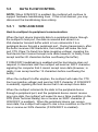
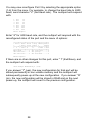
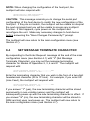
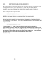
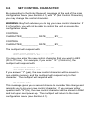
OWNER'S MANUAL
H-SERIES
MULTIPORT
CONTROLLERS
525H
528H
529H
5218H
BayTech publication #U140E043-04
Thank you for selecting a BayTech multiport controller.
The data provided in this Owner's Manual explains the various ways
you can operate your unit and configure it to your own computer
system. We suggest that you read this manual carefully before
attempting to install your multiport controller and that you place
special emphasis on correct cabling and configuration. If you have
any problems with your installation, please contact a BayTech
applications engineer for assistance.
BayTech also manufactures data communications devices that
provide buffered and non-buffered peripheral sharing. If you would
like information on any of these models, please contact BayTech
Sales/Service.
We welcome any comments you may have about our multiports. And
we hope that you will continue to look to BayTech for your data
communications needs.
NOTE: The information contained in this document is subject to
change without notice.
Copyright 1993 by Bay Technical Associates, Inc.
IBM PC, IBM PC/AT, IBM PC/XT are products of International
Business Machines Corporation.
All products or company names are trademarks of their respective
holders.
TABLE OF CONTENTS
1
GENERAL INFORMATION ........................................................................ 1
2
SPECIFICATIONS ..................................................................................... 4
3
INSTALLATION.......................................................................................... 6
3.1
3.2
3.3
3.4
UNPACKING ................................................................................
UTILITY SOFTWARE DISKETTE ................................................
POWER ........................................................................................
FACTORY DEFAULTS.................................................................
6
6
7
8
4
CABLING.................................................................................................... 9
5
OPERATION ............................................................................................ 11
5.1
USER-PROGRAMMABLE OPERATIONS ................................. 11
5.1.1
5.1.2
5.1.3
5.1.4
5.1.5
5.2
11
12
12
12
13
5.1.5.1
5.1.5.2
5.1.5.3
5.1.5.4
5.1.5.5
5.1.5.6
13
13
14
14
14
15
MODE OF OPERATION 1...............................
MODE OF OPERATION 2...............................
MODE OF OPERATION 3...............................
MODE OF OPERATION 4...............................
MODE OF OPERATION 5...............................
MODE OF OPERATION 6...............................
OPERATING IN THE DIFFERENT MODES............................... 15
5.2.1
5.2.2
5.2.3
5.2.4
5.2.5
5.2.6
5.3
5.4
THE SERIAL PORT CONFIGURATION .......................
THE MESSAGE TERMINATING CHARACTER ...........
SET DATA BLOCK LENGTH........................................
THE CONTROL CHARACTER .....................................
THE MODES OF OPERATION.....................................
OPERATING IN MODE 1..............................................
OPERATING IN MODE 2..............................................
OPERATING IN MODE 3..............................................
OPERATING IN MODE 4..............................................
OPERATING IN MODE 5..............................................
OPERATING IN MODE 6..............................................
16
17
18
18
19
19
BINARY MODE........................................................................... 20
BREAK CONDITION .................................................................. 20
5.5
DATA FLOW CONTROL ............................................................ 21
5.5.1
5.5.2
6
CONFIGURATION ................................................................................... 25
6.1
6.2
6.3
6.4
6.5
6.6
6.7
6.8
6.9
7
525H AND 529H ........................................................... 21
528H AND 5218H ......................................................... 23
MAIN CONFIGURATION MENU ................................................
STATUS......................................................................................
SET SERIAL PORT CONFIGURATION .....................................
SET MESSAGE TERMINATE CHARACTER.............................
SET DATA BLOCK LENGTH .....................................................
SET CONTROL CHARACTER...................................................
SET MODE OF OPERATION .....................................................
EXIT............................................................................................
NON-VERBOSE MODE .............................................................
25
26
27
29
30
31
32
32
33
MAINTENANCE ....................................................................................... 36
7.1
7.2
RETURNS TO THE FACTORY .................................................. 36
REPACKING FOR SHIPPING.................................................... 36
8
TECHNICAL SUPPORT........................................................................... 37
9
FEDERAL COMMUNICATIONS COMMISSION RADIO FREQUENCY
INTERFACE STATEMENT ...................................................................... 38
APPENDIX A
TROUBLESHOOTING ............................................................................. 39
APPENDIX B
INDEX ...................................................................................................... 44
The BayTech H-Series multiport controllers are flexible, multi-function
data acquisition and control units that provide cost effective data
communications for applications that require control of multiple
peripherals from a single host computer. Designed with flexibility in
mind, the H-Series controllers can be programmed to provide full
duplex communication between host and peripheral or can provide
real-time data acquisition from remote peripherals. In a typical
application, the host port may be connected to such devices as bar
code readers, cash registers, fire alarms, numerical machines,
modems, plotters, printers, security systems, and terminals.
The host computer system may individually select up to seventeen
peripheral devices and send data to the selected device. The 525H
interfaces four peripheral devices to a single host device, the 528H
and 529H interface eight peripherals, and the 5218H interfaces
seventeen peripherals. All H-Series models will simultaneously
multiplex incoming data from peripheral devices to be transmitted to
the host system. The method of data transmission from the
peripheral devices to the host system is dependent upon the mode of
operation.
The H-Series models feature six user-selectable modes of operation.
The six modes of operation are:
Mode 1
Full Duplex Communication - Allows a single host
computer to switch between a maximum of seventeen
peripheral devices. Provides bidirectional data transfer
between the host computer and the selected peripheral
device. Data received from non-selected peripheral
devices is stored in a buffer until the port is selected.
Mode 2
All messages from all ports - Provides automatic
multiplexing of all messages from all peripheral devices.
Data is buffered until a terminating character is received
or until the buffer fills. The messages are then sent to
the host device preceded by a port identification code.
Mode 3
Single message from all ports - Same as Mode 2,
except that a single message from all peripheral devices
is sent to the host device upon request.
Mode 4
All messages from selected port - Same as Mode 2,
but with specific port selection.
Mode 5
Single message from selected port - Same as Mode
3, but with specific port selection.
Mode 6
Time division multiplexing - Provides automatic
multiplexing of data from peripheral devices by
continuously scanning all ports to check for characters in
the receive buffers. If a receive buffer contains data, it
is transmitted through the host port in data blocks with
each data block preceded by a port identification code.
Transmission continues until the buffer is empty or until
a user-specified data block length has been transmitted.
In addition to the modes of operation, you may select the serial port
configuration (baud rate, word size, stop bits, parity and XON/XOFF),
the message terminate character, the data block length, and the
control character. These configuration changes are accomplished by
entering the menu-driven configuration mode. Changes are saved in
non-volatile memory. The H-Series models will translate between
peripheral devices of different configurations.
2
Figure 1 below shows six applications, one for each mode of
operation.
Figure 1
INTERFACE: EIA-232C (CCITT V.24), -12v mark, +12v
space. Optional EIA-422A (Option 17) and current loop
(Option 12).
TRANSMISSION: Asynchronous.
FACTORY POWER-UP DEFAULT CONFIGURATIONS:
Baud rate: 9600.
Word size: 8 bits.
Parity: None.
Stop bits: 1.
XON/XOFF: Disabled.
Control character: Control-T (14 Hex).
Data block length: 32 characters.
Terminating character: Carriage Return (0D Hex).
Mode of operation: Mode 1 - Port expansion/sharing.
USER-PROGRAMMABLE CONFIGURATIONS:
Easy to configure using on-screen menus through the
host port. Choices are saved in non-volatile memory to
become the new power-up default configuration.
Baud rate: 110, 135, 300, 600, 1200, 2400, 4800,
9600. 19200 is available on the 525H only.
Other rates optional.
Word size: 5, 6, 7 or 8 bits.
Parity: Even, odd or none.
Stop bits: 1, 1 1/2 or 2.
XON/XOFF: Enabled or disabled.
Control character: Any code from 00 Hex to 7F Hex.
Terminate character: Any code from 00 Hex to
7F Hex.
Data block length: 1 to 250 characters.
Mode of operation: 1 through 6.
4
BUFFER SIZE: 525H/529H - 3.7K Rx/256 byte Tx per port
standard; the 525H optionally available with 7.7K Rx/256
byte Tx per port.
528H/5218H - 256-byte Rx/256-byte Tx per port.
POWER: 525H - 115 VAC, 50/60 Hz, maximum .2A.;
optional 230 VAC, 50/60 Hz, maximum .1A;
528H/529H/5218H - 115 VAC, 50/60 Hz., maximum
.3A.; optional 230 VAC, 50/60 Hz., maximum .2A.
ENVIRONMENT: 0 degrees to 50 degrees C temperature;
5% to 95% humidity.
DIMENSIONS: 525H - 8 x 7 1/2 x 2 1/4 inches;
528H/529H - 10 1/8 x 8 x 3 inches;
5218H - 16 3/4 x 10 1/8 x 3 1/2 10 inches.
WEIGHT: 525H - 3 lbs.; 528H/529H - 5 lbs.,
5218H - 9 1/2 lbs.
INDICATORS: 1 green power LED; red port connection
status LEDs.
CONNECTORS: DB-25 female DCE ports; any combination
of DTE (male) DCE (female) ports optional.
HANDSHAKING: CTS/DTR; selectable XON/XOFF.
UL AND CSA LISTED
MOUNTING: Desk-top standard; rack-mount accessories
optional.
WARRANTY: One full year.
After opening the box, check the packing list that comes with your
multiport to ensure that you have received all components. At a
minimum you should have received the unit, this manual and any
applicable addendums, and a software utility diskette. Also check the
unit to make certain that it did not receive damage during shipping. If
items are missing or damage did occur, please contact BayTech
technical support at 1-800-523-2702.
BayTech provides utility software for DOS compatible PCs to assist
you in configuring your H-Series model.
IMPORTANT: Copy the BayTech original diskette onto a blank
diskette and store the original in a safe place. Read your operating
systems manual for copying instructions.
This diskette contains the following programs: REMCONFG.COD,
SMODE.EXE, TERM.EXE, AND README.RDM. The H-Series
models do not utilize the REMCONFG.COD file. TERM.EXE is a
terminal emulation program used to configure the various features of
the unit. SMODE.EXE is a program used to configure COM ports of
DOS compatible machines to operate at speeds up to 115,200 bps.
Please review the README.RDM file to obtain instructions for
TERM.EXE and SMODE.EXE. To view the README.RDM file on
your screen, first insert the diskette into your PC's disk drive and then
enter the command TYPE README.RDM from your disk drive
prompt. To print this file, enter the command
COPY README.RDM LPT1: from your disk drive prompt.
6
All standard models require 115VAC, 50/60 Hz. power and come with
a three-prong power cord. Do not attempt to operate the unit with a
two-prong socket or adapter. 230 VAC, 50/60 Hz. is optional.
All H-models power-up when you depress the power switch on the
back of the unit to "ON". The green power LED on the panel will
illuminate when power is applied.
CAUTION: Power should be turned off anytime cables are to be
installed or removed. Do not attempt to remove the top panel and
make any internal changes. Any such changes must be made by an
authorized service technician or by BayTech. Please contact
BayTech at 1-800-523-2702 for more information.
NOTE: Before you proceed with installation, make certain that the
device connected to the host port is setup to have the same
configuration as the multiport host port. The H-Series multiports are
factory configured as follows:
Serial ports power up from the factory at:
9600 baud rate
8 word size
1 stop bit
No parity
XON/XOFF disabled
Control character: Control-T (14 Hex).
Terminating character: Carriage Return (0D Hex).
Data block length: 32 characters.
Mode of operation: Mode 1 - Port expansion/sharing.
If the factory default configuration for all ports is not satisfactory for
your application, you must reconfigure the multiport by entering the
configuration mode (see Section 6). The controlling or host device is
connected via cable to the host port on the H-models. This is Port 5
of the 525H, Port 9 of the 528H and 529H, and Port 18 of the 5218H.
Peripheral devices are connected via cable to any of the remaining
ports. They need not be installed in any specific order. Peripheral
ports not used may be left empty.
8
IMPORTANT: Before you proceed with cabling, you must know
whether the devices you are connecting to your multiport are DTE
(Data Terminal Equipment) or DCE (Data Communication
Equipment). The following devices are generally DTE: terminals,
printers, and computers like the IBM PC. The following devices are
DCE: modems and some computers.
If your device transmits data on Pin 2 or receives data on Pin 3, it is
DTE. If your device receives data on Pin 2 and transmits data on Pin
3, it is DCE. However, to verify the interface requirements for your
device, please refer to the Owner's Manual for that device.
BayTech's standard configuration of its multiports is all ports DCE with
DB-25 female connectors. DCE ports use the following signals for
communication:
DCE PORT SIGNALS
Pin
EIA-232
Signal
Direction
Description
1
PGND
----
2
TX
Input
3
RX
Output
4
RTS
Input
5
CTS
Output
-12V when multiport's buffer is full.
6
DSR
Output
+12V when multiport powers-up.
7
SGND
----
8
DCD
Output
20
DTR
Input
Protective ground
Data in
Data out
Internally enabled if no wire connected
(normally not used).
Signal ground
+12V when multiport powers-up.
Transmit enabled when +12 V.
If you are interfacing a DCE device to a DTE device, you must use a
one-to-one straight cable as shown in Figure 2. If you are interfacing
a DCE device to a DCE device, or a DTE device to a DTE device, you
must use a crossed cable as shown in Figure 3. Input handshaking
lines are enabled if nothing is connected, allowing the system to
operate with only Tx, Rx and GND connected.
500H MODEL - DCE
MALE DB-25
1
PGND
2
TXD
3
RXD
4
RTS
5
CTS
6
DSR
7
SGND
8
DCD
20
DTR
DTE DEVICE
FEMALE DB-25
PGND
1
TXD
2
RXD
3
RTS
4
>
CTS
5
>
DSR
6
SGND
7
DCD
8
DTR
20
<
>
<
>
<
Figure 2 - 500H Series (DCE) to DTE Device
500H MODEL - DCE
MALE DB-25
DCE DEVICE
FEMALE DB-25
2
TXD
TXD
2
3
RXD
RXD
3
4
RTS
RTS
4
5
CTS
CTS
5
6
DSR
DSR
6
7
SGND
SGND
7
8
DCD
DCD
20
DTR
DTR
Figure 3 - 500H Series (DCE) to DCE Device
10
8
20
This section discusses user-programmable operations (see Section
5.1), operating in the different modes (see Section 5.2), binary mode
(see Section 5.3), break condition (see Section 5.4), and data flow
control (see Section 5.5).
You may select from six modes of operation. You may also select the
serial port configuration and handshaking for each individual port, the
data block length, the message terminating character, and the control
character. These changes are made by accessing the menu-driven
configuration mode.
The multiport will translate for devices using different serial
configurations. You may set the baud rate, word size, stop bits, parity
and XON/XOFF handshaking for each individual port.
Factory default configuration on all ports is 9600 baud rate, 8
word size, 1 stop bit, no parity, XON/XOFF disabled.
This is a single character that indicates a completed message to the
multiport in Modes of Operation 2, 3, 4 and 5. Data is held in the
buffer of the multiport until the message terminating character is
received from the peripheral device which defines a complete
message. The message is eventually sent to the host device
depending on which mode of message multiplexing the multiport is
operating in. The single message terminating character is in the form
of any two-digit hexadecimal character from 00 Hex to 7F Hex.
Factory default is Carriage Return (0D Hex).
The data block length is the maximum number of characters per data
block transmitted out of the host port while operating in Mode 6. You
may select a data block length of 1 to 250 characters.
Factory default is 32 characters.
The control character is used to select specific peripheral ports, to
request messages, for port identification purposes, and to access
configuration mode. To select a peripheral port, the host device
sends the control character followed by the desired peripheral port
number. To request messages in Mode 3 of operation, the host
device sends the control character followed by capital S. To request
messages in Mode 4 and Mode 5 of operation, the host device sends
the control character, capital S, and the desired peripheral port
number. In Mode 6 of operation, the host port sends the control
character and the source peripheral port number preceding each data
block. The control character may consist of any single character from
00 Hex to 7F Hex.
Factory default is Control-T (14 Hex).
12
NOTE: For illustration purposes, the factory default control character
(Control-T) will be used in the following descriptions of the Modes of
Operation. Section 5.2 provides more detail for operating in the
various modes.
Mode of Operation 1 increases input/output by interfacing a single
port on a computer with full duplex communication to four, eight, or
seventeen peripheral devices. The communication is full duplex
between the host device and the selected peripheral device. For the
host device to select a specific peripheral port, it would send Control-T
followed by the desired peripheral port number. The host remains
connected to the selected peripheral port until another peripheral port
is selected.
NOTE: Peripheral port selection is done in the manner described
above for all Modes of Operation.
Factory default is Mode 1 with the host port connected to Port 2
on power-up.
Mode of Operation 2 provides multiplexing to the host port of all
messages from all peripheral ports automatically. Data is buffered
until an end of message terminating character is received or until the
buffer is full. The messages are sent to the host device preceded by
a port identification number corresponding to the port number of the
peripheral device that actually sent the message.
Mode of Operation 3 provides multiplexing to the host port of a single
message from all peripheral ports. Single messages from each
peripheral port are sent to the host device only when a request for
messages command is received. When the host device sends the
request for messages command, the multiport sends a complete
message from each peripheral port to the host device preceded by a
port identification number corresponding to the port from which the
message came. Complete messages are sent to the host port in a
round-robin fashion.
Mode of Operation 4 provides multiplexing to the host port of all
messages from a selected port. You select a specific peripheral port
and all complete messages in the buffer for that port are transmitted
to the host device automatically with each message preceded by a
port identification number.
Mode of Operation 5 provides multiplexing to the host port of a single
message from a selected port. You select a specific peripheral port
and a single message from that port is sent to the host device when
the host device requests it with each message preceded by a port
identification code.
14
Mode of Operation 6 provides time-division multiplexing. In this
mode, the multiport continuously scans all peripheral ports to check
for characters in the receive buffers. If a receive buffer contains data,
the data is transmitted to the host device preceded by a port
identification code corresponding to the peripheral port number from
which the data block came. Transmission continues until the buffer is
empty or until a user-specified data block length has been
transmitted.
A typical application using an H-Series multiport controller would have
a host computer, such as an IBM PC, connected to the host port, and
various peripheral devices (such as cash registers, digital laboratory
instruments, bar code readers, numerical machines, printers,
modems, terminals, etc.) connected to the peripheral ports.
Regardless of the mode of operation, the host device may connect
and send data to a specific peripheral port by sending the control
character and the desired peripheral port number followed by the
data. The control character and peripheral port number are trapped
and therefore not passed through to the selected peripheral port. For
demonstration purposes, we will use the default control character,
Control-T.
NOTE: The 8th bit or parity bit is masked from the control character
before it is examined, allowing you to send the control character with
odd or even parity. Therefore, when 8 data bits are being sent, only
the first seven data bits are examined.
In modes of operation 2 through 5, each message sent to the host
device is preceded by the port number of the peripheral port that
received the message. This number may range from 1 to 4 on the
525H, 1 to 8 on the 528H and 529H, and 01 to 17 on the 5218H.
To clear the receive buffer for a selected peripheral port, send the
control character followed by ASCII capital R. All complete or partial
messages in the buffer of the selected peripheral port will be erased
regardless of the mode of operation.
In Mode of Operation 1, the H-Series multiport will provide full duplex
communication between the host port and the selected peripheral
port. Port 2 is the selected peripheral port when the multiport powers
up. The host port and the selected peripheral port will remain
connected until another peripheral port is selected. Data received by
non-selected peripheral devices will be stored in the multiport's buffer
and sent to the host device when the peripheral port is selected.
When switching ports, there may be some question as to which is the
last character received from the current port and which is the first
character received from the new port. A way to avoid this confusion
when selecting a new port is to wait two character times between
Control-T and the port number. When the multiport receives
Control-T, it stops the input of data to the host UART from the current
port. However, since the UART has some buffer, up to two characters
may still be sent to the host device. The multiport does not start
loading data from the new port into the host UART until the new port
number is received. This delay may be accomplished by sending a
string of ASCII zeros (30 Hex) between Control-T and the new port
number.
16
For example, suppose the host device is transmitting and receiving
data from Port 1 and you wish to switch to Port 2.
1.
2.
3.
4.
Send Control-T to the multiport.
Wait two character times.
Read computer input buffer.
If there are no characters in the PC's input buffer, send ASCII
2. This will switch the PC to Port 2. If there are characters in
the PC's input buffer, you may send ASCII 1 to continue
communicating with Port 1 or ASCII 2 to switch to Port 2. Any
characters received after sending the new port number will be
from the new port.
The multiport does not start loading data from the new peripheral port
into the host port I/O module until the new peripheral port number is
received.
Mode of Operation 2 provides automatic message multiplexing
between the host port and up to seventeen peripheral ports. Data
received from the peripheral devices is treated as messages. A
message begins when a peripheral port receives a character from the
device connected to it. A message is completed when the message
terminating character is received or when the buffer is full. Either
condition will cause data to be transferred to the host device a
message at a time, with the multiport inserting the peripheral port
number prior to the actual message.
Messages will be sent automatically to the host device in a
round-robin fashion (i.e., if the multiport is sending a message from
Port 1, Port 2 will be examined next for a complete message, then
Port 3, etc.).
NOTE: The host device may select and transmit data to any
peripheral port while simultaneously receiving all messages from all
peripheral ports.
Mode of Operation 3 provides message multiplexing to the host port
of single messages from all peripheral ports upon request from the
host device. A single message from all ports is sent to the host
device only when a command is received from the host device. The
request for messages command is the control character (Control-T
default) followed by ASCII capital S. If there are no messages, the
host port will send a Line Feed character to the host device.
NOTE: The host device may select and transmit data to any
peripheral port while simultaneously receiving single messages from
all peripheral ports.
In Mode of Operation 4, all messages are sent to the host port from a
selected peripheral port. The host device may receive all complete
messages in the buffer of a selected port by sending the control
character followed by ASCII capital S and the desired port number (1
to 4 for the 525H, 1 to 8 for the 528H and 529H, and 01 to 17 for the
5218H).
NOTE: The host device may select and transmit data to any
peripheral port while simultaneously receiving all messages from a
specific peripheral port.
18
In Mode of Operation 5, a single message is sent to the host port from
a selected peripheral port. Operation in Mode 5 enables the host
device to receive one complete message from a selected peripheral
port by sending the control character followed by ASCII capital S and
the desired port number (1 to 4 for the 525H, 1 to 8 for the 528H and
529H, and 01 to 17 for the 5218H). If no message is available, the
host port will transmit a Carriage Return/Line Feed.
NOTE: The host device may select and transmit data to any
peripheral port while simultaneously receiving single messages from a
specific peripheral port.
Mode of Operation 6 provides time-division multiplexing. The internal
processor in Mode 6 continuously scans all peripheral ports checking
for characters in the receive buffers. If a receive buffer contains
characters, the characters are transmitted through the host port
preceded by a port identification code which consists of the control
character followed by the peripheral port number. Transmission
continues until the buffer is empty or until a user-defined maximum
data block length has been transmitted. After transmission is
completed, the multiport will continue its scanning sequence.
If a control character is received by the multiport from a peripheral
device, a second control character is added automatically. This
technique allows you to detect the control character as a data
character when it is sent through the multiport.
NOTE: The host device may select and transmit data to any
peripheral port while simultaneously receiving data blocks from all
peripheral ports.
Binary mode allows all data received by the host port to be passed
through to the selected peripheral port including the control character.
Binary mode is useful when sending binary data (i.e., data in a format
other than ASCII) to the selected peripheral port and it is possible that
the bit pattern for the control character may be part of the data
stream. Binary mode is also useful if you wish to pass the control
character through to the selected peripheral device.
To access binary mode, the host device sends the control character
(factory default is Control-T) followed by ASCII capital B. While
operating in binary mode, you will unable to access configuration
mode or select a different peripheral port until you exit binary mode.
To exit binary mode, the host port must see a "BREAK CONDITION".
NOTE: You may access binary mode regardless of the mode of
operation you operating in.
The H-Series models will pass a "BREAK CONDITION" through to
any selected peripheral port in any of the six modes of operation
provided you are not operating in binary mode.
20
NOTE: When XON/XOFF is enabled, the multiport will continue to
support hardware handshaking lines. If this is not desired, you may
disconnect the handshaking lines entirely.
Host-to-multiport-to-peripheral communication:
When the host device transmits data to a peripheral device through
the multiport's host port, the data is received and stored in a
256-character transmit buffer which in turn retransmits it to a
peripheral device through a peripheral port. During transmission, after
the buffer receives 236 characters, the multiport will make the host
port CTS (Clear-To-Send) line false (negative voltage), signaling the
host device that it cannot accept more data (however, in reality it can
accept another 20 characters before overflowing the buffer).
If XON/XOFF handshaking is enabled and the host device does not
respond, 8 characters later the multiport will send an XOFF character,
signaling the computer that it cannot accept more data (however, in
reality it can accept another 12 characters before overflowing the
buffer).
When the multiport's buffer empties, the multiport will make the CTS
line true (positive voltage) and send an XOFF character (if XON/XOFF
is enabled), signaling the host device that it can accept more data.
When the multiport retransmits the data to the peripheral device
through a peripheral port, and the peripheral device cannot receive
any more data, the multiport will expect to see a false condition on the
DTR (Data Terminal Ready) line or receive an XOFF character (if
XON/XOFF is enabled). When the peripheral device can receive
more data, the multiport will expect to see a true condition on the DTR
line or receive an XON character (if XON/XOFF is enabled).
Peripheral-to-multiport-to-host communication:
When a peripheral device transmits data to the host device through a
peripheral port, the data is received and stored in a 3740-character
receive buffer (or 7740 receive buffer for 525 units with Option 20)
which in turn retransmits it to the host device through the host port.
After the buffer receives 3720 characters (or 7720 characters for 525
units with Option 20), the multiport will make the peripheral port CTS
(Clear-To-Send) line false (negative voltage), signaling the peripheral
device that it cannot accept more data (however, in reality it can
accept another 20 characters before overflowing the buffer).
If XON/XOFF is enabled and the peripheral device does not respond,
8 characters later the multiport will send an XOFF character, signaling
the peripheral device that it cannot accept more data. (However, in
reality it can accept another 12 characters before overflowing the
buffer.)
When the buffer empties, the multiport will make the CTS line true
(positive voltage) and send an XON character (if XON/XOFF is
enabled), signaling the peripheral device that it can accept more data.
When the multiport is sending data to the host device through the host
port and the host device cannot receive any more data, the multiport
will expect to see a false condition on the DTR line or receive an
XOFF character.
22
Host-to-multiport-to-peripheral communication
When the host device transmits data to a peripheral device through
the multiport's host port, the data is received and stored in a 256character transmit buffer which in turn retransmits it to a peripheral
device through a peripheral port. During transmission, after the buffer
receives 236 characters, the multiport will make the host port's CTS
(Clear-To-Send) line false (negative voltage), signaling the host
device that it cannot accept more data (however, in reality it can
accept another 20 characters before overflowing the buffer).
If XON/XOFF handshaking is enabled and the host device does not
respond, 8 characters later the multiport will send an XOFF character,
signaling the computer that it cannot accept more data (however, in
reality it can accept another 12 characters before overflowing the
buffer).
When the multiport's buffer empties, the multiport will make the CTS
line true (positive voltage) and send an XON character (if XON/XOFF
is enabled), signaling the host device that it can accept more data.
When the multiport retransmits the data to the peripheral device
through a peripheral port, and the peripheral device cannot receive
any more data, the multiport will expect to see a false condition on the
DTR (Data Terminal Ready) line or receive an XOFF character (if
XON/XOFF is enabled). When the peripheral device can receive
more data, the multiport will expect to see a true condition on the DTR
line or receive an XON character (if XON/XOFF is enabled).
Peripheral-to-multiport-to-host communication
When a peripheral device transmits data to host device through the
multiport's peripheral port, the data is received and stored in a
256-character receive buffer which in turn retransmits it to the
computer through the host port. After the buffer receives
236-characters, the multiport will make the peripheral port CTS
(Clear-To-Send) line false (negative voltage), signaling the peripheral
device that it cannot accept more data (however, in reality it can
accept another 20 characters before overflowing the buffer).
If XON/XOFF is enabled and the peripheral device does not respond,
8 characters later the multiport will send an XOFF character, signaling
the peripheral device that it cannot accept more data. (However, in
reality it can accept another 12 characters before overflowing the
buffer.)
When the buffer empties, the multiport will make the CTS line true
(positive voltage) and send an XON character, signaling the peripheral
device that it can accept more data.
When the multiport is sending data to the host device through the host
port and the host device cannot receive any more data, the multiport
will expect to see a false condition on the DTR line or receive an
XOFF character (if XON/XOFF is enabled).
24
To access the configuration mode of the multiport, connect a dumb
terminal (or a PC running a terminal emulation program) to the host
port: Port 5 of the 525H, Port 9 of the 528H and 529H, or Port 18 of
the 5218H. This port is factory configured at 9600 baud rate, 8 word
size, 1 stop bit, no parity, and XON/XOFF disabled.
If you do not have a dumb terminal or a terminal emulation program,
BayTech supplies a utility diskette which includes instructions to put
an IBM PC or compatible into a dumb terminal mode (see Section
3.2).
Send from this device the control character (factory default is
Control-T - 14 Hex) followed by ASCII capital C (43 Hex). The
multiport should respond with the main configuration menu as shown
in Section 6.1. From this point on, configuration of the multiport will
be menu-driven. While in configuration mode, you may send
Control-S to stop scrolling and Control-Q to continue scrolling.
The multiport will respond to the receiving of the control character and
capital C with an identification block and a configuration menu of the
options available, similar to the following for the 528H:
Bay Technical Associates
Model 528H Multiport Controller
Copyright 1986
Revision 2.06
Status......................................1
Set Serial Port Configuration...............2
Set Message Terminate Character.............3
Set Data Block Length.......................4
Set Control Character.......................5
Set Mode of Operation.......................6
Exit........................................X
Enter Request:
NOTE: Menu selection is case sensitive. It is recommended that your
keyboard be in the CAPS LOCK position. In the configuration mode,
some characters are displayed with a HEX notation since all
combinations from 00 Hex TO 7F Hex may be selected.
By responding to the Enter Request: message at the end of the main
configuration menu (see Section 6.1) with "1" (Status), you may view
the status of all ports and the current operation protocol. The
multiport will respond as follows:
| Port • Baud •Word
|
• Rate •Size
|
|
1 • 9600 • 8
|
2 • 9600 • 8
|
3 • 9600 • 8
|
4 • 9600 • 8
|
5 • 9600 • 8
|
6 • 9600 • 8
|
7 • 9600 • 8
|
8 • 9600 • 8
|
9 • 9600 • 8
•Stop •Parity •Xon/ |
•Bits •
•Xoff |
•
•
•
•
•
•
•
•
•
1
1
1
1
1
1
1
1
1
•
•
•
•
•
•
•
•
•
None
None
None
None
None
None
None
None
None
•
•
•
•
•
•
•
•
•
Off
Off
Off
Off
Off
Off
Off
Off
Off
|
|
|
|
|
|
|
|
|
Press Any Key to Continue
OPERATION PROTOCOL
••••••••••••••••••••••••••••••••••••••••••••••
• Mode • Control Char. • RCV • RCV • RCV •
• of
•••••••••••••••••• Port • Term •Block •
• Oper.• XMIT • RCV
• I.D. • Chr. •Length•
••••••••••••••••••••••••••••••••••••••••••••••
• 1
• 14H n • 14H n • N/A • N/A • N/A •
• 2
• 14H n • N/A
• n
• 0DH • N/A •
• 3
• 14H n • 14H S • n
• 0DH • N/A •
• 4
• 14H n • 14H Sn • n
• 0DH • N/A •
• 5
• 14H n • 14H Sn • n
• 0DH • N/A •
• 6
• 14H n • N/A
•14H n • N/A • 032 •
••••••••••••••••••••••••••••••••••••••••••••••
H = Hexadecimal
S = 53H
n = ASCII Port Number (1 to 9 or 31H to 39H)
N/A = Not Applicable
Current
Current
Current
Current
Terminate Character is.............0DH
Block Length is....................032
Control Character is...............14H
Mode of Operation is.................1
Press Any Key To Continue
26
Status.......................................1
Set Serial Port Configuration................2
Set Message Terminate Character..............3
Set Data Block Length........................4
Set Control Character........................5
Set Mode of Operation........................6
Exit.........................................X
Enter Request:
NOTE: "n" shown on the previous page indicates single-digit port
numbers on the 525H and 528H. The menus of the 5218H will
display nn indicating two-digit port numbers.
By responding to the Enter Request: message at the end of the main
configuration menu (see Section 6.1) with "2" (Set Serial Port
Configuration), you may change the configuration of each port (i.e.
baud rate, word size, stop bits, parity and XON/XOFF handshaking).
Note that each port is configured individually. The multiport will
respond with:
Enter Port Number (0=Exit),Return:
You should then enter the number of the port that you wish to
reconfigure, followed by Carriage Return. Note that if 0 (zero) is
entered, you will exit back to the main configuration menu.
For example, if you enter " 3" and Carriage Return for Port 3, the
multiport will respond with the current status of Port 3 and a menu of
the available options:
•••••••••••••••••••••••••••••••••••••••••
• Port • Baud • Word • Stop •Parity•Xon/•
•
• Rate • Size • Bits •
•Xoff•
•••••••••••••••••••••••••••••••••••••••••
• 3
• 9600 • 8
•
1 • None • Off•
•••••••••••••••••••••••••••••••••••••••••
Exit/Save..........1
Set baud rate......2
Set word size......3
Enter request:
Set stop bits....4
Set parity.......5
Set Xon/Xoff.....6
You may now reconfigure Port 3 by selecting the appropriate option
(1-6) from the menu. For example, to change the baud rate to 2400
baud, send character "2" (Set baud rate). The multiport will respond
with:
1
2
3
4
5
6
7
8
For
For
For
For
For
For
For
For
110
135
300
600
1200
2400
4800
9600
Enter request:
Enter "6" for 2400 baud rate, and the multiport will respond with the
reconfigured status of the port and the menu of options:
•••••••••••••••••••••••••••••••••••••••••
• Port • Baud • Word • Stop •Parity•Xon/•
•
• Rate • Size • Bits •
•Xoff•
•••••••••••••••••••••••••••••••••••••••••
• 3
• 2400 • 8
• 1
• None • Off•
•••••••••••••••••••••••••••••••••••••••••
Exit/Save.........1 Set stop bits......4
Set baud rate.....2 Set parity.........5
Set word size.....3 Set Xon/Xoff.......6
Enter request:
If there are no other changes for this port, enter " 1" (Exit/Save), and
the multiport will respond with:
Save Changes Permanently? (Y/N):
If you answer "Y" (yes), the new configuration for that port will be
stored permanently in non-volatile memory and the multiport will
subsequently power-up at the new configuration. If you answer "N"
(no), the new configuration will be stored in RAM and on the next
power-up, the multiport will revert to the previous configuration.
28
NOTE: When changing the configuration of the host port, the
multiport will also respond with:
Change Device to NEW Configuration
Before Answering This Request.
CAUTION: This message reminds you to change the serial port
configuration of the host device to match the new configuration of the
host port. If they do not match, the multiport will be unable to interpret
the next command and you will be unable to access any multiport
function. If this happens, cycle power on the multiport and
reconfigure the unit. Make any necessary changes to host device
before answering the "Save Changes Permanently?" prompt.
The multiport will now return to the main configuration menu (see
Section 6.1).
By responding to the Enter Request: message at the end of the main
configuration menu (see Section 6.1) with "3" (Set Message
Terminate Character), you may set the message terminating
character for Modes of Operation 2, 3, 4 and 5. The multiport will
respond with:
Current Terminate Character is.............0DH
Enter Terminate Character in Hex..........:
Enter the terminating character that you wish in the form of a two-digit
hexadecimal character (00 to 7F Hex). For example, if you enter 0A
(Line Feed), the multiport will respond with:
Current Terminate Character is.............0AH
Save Changes Permanently? (Y/N):
If you answer "Y" (yes), the new terminating character will be stored
permanently in non-volatile memory and the multiport will
subsequently power-up with the new terminating character in effect. If
you answer "N" (no), the new terminating character will be stored in
RAM and lost upon next power-up. The multiport will now return to
the main configuration menu (see Section 6.1).
By responding to the Enter Request: message at the end of the main
configuration menu (see Section 6.1) with "4" (Set Data Block
Length), you may change the data block length used in Mode 6.
The multiport will respond with:
Current Block Length is...................032
Enter Block Length (1 to 250)............:
NOTE: Carriage Return is required after the new length.
Enter the block length that you desire, followed by Carriage Return.
For example, if you enter "100" and Carriage Return, the multiport will
respond with:
Current Block Length is..................100
Save Changes Permanently? (Y/N):
If you answer "Y" (yes), the new block length will be saved in
non-volatile memory, and the multiport will subsequently power-up at
that new length. If you answer " N" (no), the new data block length will
be stored in RAM and will be lost upon next power-up. The multiport
will now return to the main configuration menu (see
Section 6.1).
30
By responding to the Enter Request: message at the end of the main
configuration menu (see Section 6.1) with "5" (Set Control Character),
you may change the control character.
WARNING: BayTech advises you to log your new control character. If
it is forgotten, you will not be able to control the unit or access the
configuration mode.
CONTROL
CHARACTER____________ DATE______ BY___
CONTROL
CHARACTER____________ DATE______ BY___
The multiport will respond with:
Current Control Character is...............14H
Enter Control Character in Hex.............:
You may now enter the new control character that you want in HEX
(00 to 7F Hex). For example, if you enter " 15 " (Control-U), the
multiport will respond with:
Current Control Character is...............15H
Save Changes Permanently? (Y/N):
If you answer "Y" (yes), the new control character will be saved in
non-volatile memory, and the multiport will respond only to that
character. The multiport will respond with:
Are You Sure? (Y/N):
This message gives you a second chance to consider this change and
reminds you to log your new control character. If you answer either
question with "N" (no), the new control character will be stored in RAM
and lost upon next power-up. The multiport will return to the main
configuration menu (see Section 6.1).
!
By responding to the Enter Request: message at the end of the main
configuration menu (see Section 6.1) with "6" (Set Mode of
Operation), you may change the current mode of operation. The
multiport will respond with:
MODE OF OPERATION
Full Duplex Communication...................1
All Messages from All Ports.................2
Single Message from All Ports...............3
All Messages from Selected Port.............4
Single Message from Selected Port...........5
Time Division Multiplexer...................6
Exit........................................X
Current Mode is: 1
Enter request:
You may now enter the mode of operation that you wish. The
multiport will respond with:
Save Changes Permanently? (Y/N):
If you answer "Y" (yes), the new mode will be saved in non-volatile
memory and will become the new power-up mode. If you answer "N"
(no), the new mode of operation will be stored in RAM and will be lost
upon next power-up. The multiport will now return to the main
configuration menu (see Section 6.1).
"
By responding to the Enter Request: message at the end of the main
configuration menu (see Section 6.1) with capital "X" (Exit), you will
exit the configuration mode and return to the operation mode.
32
#
Multiports power-up in the verbose or menu-driven mode. Only in the
menu-driven mode can changes be saved permanently in non-volatile
memory. Non-verbose mode allows the host device to configure the
multiport be sending an ASCII character string which may be
preferable in some instances. This mode applies only to configuration
and does not affect operations. The non-verbose mode is basically
the same as the verbose mode, except that no menus are sent from
the multiport. Also, changes made in the non-verbose mode are not
saved in non-volatile memory and will be lost upon power-down,
whereupon the power-up default configuration will again be in effect.
The non-verbose mode is selected by sending to the host port of the
multiport the control character (factory default is Control-T) followed
by ASCII capital I.
You may now reconfigure by selecting numbers from these menus:
A. MAIN MENU
Set Serial Port Configuration...........2
Set Message Terminate Character.........3
Set Data Block Length...................4
Set Control Character...................5
Set Mode of Operation...................6
Exit....................................X
B. SET SERIAL PORT CONFIGURATION MENU
Enter port number and Carriage Return.
Exit/Save........................1
Set baud rate....................2
Set word size....................3
Set stop bits....................4
Set parity.......................5
Set Xon/Xoff.....................6
a) SET BAUD RATE MENU
110..................1
135..................2
300..................3
600..................4
1200.................5
2400.................6
4800.................7
9600.................8
b) SET WORD SIZE MENU
5....................1
6....................2
7....................3
8....................4
c) SET STOP BITS MENU
1....................1
1 1/2................2
2....................3
d) SET PARITY MENU
None.................1
Even.................2
Odd..................3
e) SET XON/XOFF MENU
Enabled.............Y
Disabled............N
C. SET MESSAGE TERMINATE CHARACTER
Enter terminating character in the form of a two-digit hexadecimal
character (00-7F Hex).
D. SET DATA BLOCK LENGTH
Enter data block length (1 to 250 characters) followed by Carriage
Return.
E. SET CONTROL CHARACTER
Enter control character in HEX (00-7F Hex).
F. SET MODE OF OPERATION
Enter mode of operation (1 to 6).
34
For example, to configure Port 2 in the non-verbose mode at 300
baud rate, 7 bit word size, 2 stop bits, even parity, XON/XOFF
enabled, line feed terminating character, data block length 250,
control character Control-T, mode of operation 6, and XON/XOFF
enabled, send the following character string:
^TI^TC22*233343526Y130A4250*51466X.
This breaks down as follows:
^T indicates control character.
I indicates non-verbose mode.
^T indicates control character.
C indicates Configuration Mode.
2 indicates Set Serial Port Configuration.
2 indicates Port 2.
* indicates Carriage Return.
2 indicates Set Baud Rate.
3 indicates 300 Baud.
3 indicates Set Word Size.
3 indicates 7 Word Size.
4 indicates Set Stop Bits.
3 indicates 2 Stop Bits.
5 indicates Set Parity.
2 indicates Even Parity.
6 indicates Set XON/XOFF.
Y indicates XON/XOFF enabled.
1 indicates Exit to Main Menu.
3 indicates Set Message Terminate Character.
0A indicates Line Feed Terminating Character in Hex.
4 indicates Set Data Block Length.
250 indicates Data Block Length.
* indicates Carriage Return.
5 indicates Set Control Character.
14 indicates Control-T in HEX.
6 indicates Set Mode of Operation.
6 indicates Mode of Operation 6.
X indicates Exit to Operation Mode.
To return to the verbose mode, enter the multiport Control-T (or
current control character) followed by ASCII capital J. If no other
changes are needed, you may begin operations with your multiport
controller.
!
Since there are no adjustments and no moving parts in a multiport,
preventive maintenance is unnecessary.
!
If you find it necessary to return your multiport to the factory for
warranty work or factory-set changes, follow the procedure listed
under Section 7.2 for repacking.
Before you ship your unit, please call BayTech to get a Return
Authorization Number. BayTech cannot accept warranty or no-charge
returns without this number.
!
If you need to repack your unit for shipping, please choose a heavy
cardboard box for packing. Surround your unit with sufficient
insulation (a minimum of 2-inches) to withstand the rigors of transport.
Be sure to seal the box securely with strapping or packing tape.
Masking tape or cellophane tape is not recommended.
36
If you have problems with your H-Series multiport controller, BayTech
has a staff of applications engineers on duty to assist you from 7 am
to 6 pm (CST or CDT), Monday through Friday. When you call
BayTech, please have the following information available which will
help to answer your questions more efficiently:
1.
Identify which model you are using and have the serial number
handy (located on the back of the unit).
2.
Identify what host device and peripheral devices you have
connected to your H-Series multiport controller.
3.
Identify any special equipment you are using (for example,
in-line spoolers, networks, software drivers, etc.).
4.
Identify what cables you are using, what the lengths of the
cables are, and who sold you the cables.
5.
Identify any special options you may have ordered.
6.
Identify the software packages you are using.
7.
If possible, have a print-out of the unit's configuration status
ready when you call.
Always call BayTech before dismantling your equipment and
returning your H-Series multiport to BayTech for repair.
Bay Technical Associates, Inc.
P.O. Box 387, 200 N. Second Street
Bay Saint Louis, Mississippi 39520 U.S.A.
Phone: 228/467-8231 or 800/523-2702 (outside Mississippi)
Fax: 601-467-4551
Web Site: baytechdcd.com
$
%
This equipment generates and uses radio frequency energy and, if not
installed and used properly (that is, in strict accordance with the
manufacturer's instructions) may cause interference to radio and
television reception. The equipment has been type tested and found
to comply within the limits for a Class A computing device in
accordance with the specifications in Subpart J of Part 15 of FCC
rules, which are designed to provide reasonable protection against
such interference in a residential installation. However, there is no
guarantee that interference to radio or television reception will not
occur in a particular installation. If this equipment does cause
interference to radio or television reception, which can be determined
by turning the equipment off and on, the user is encouraged to try to
correct the interference by one or more of the following measures.
1.
2.
3.
4.
Reorient the receiving antenna.
Relocate the computer equipment with respect to the
receiver.
Move the computer away from the receiver.
Plug the computer into a different outlet so that
computer and receiver are on different branch circuits.
If necessary, the user should consult the dealer or an experienced
radio/television technician for additional suggestions. The Federal
Communications Commission has prepared a booklet entitled "How to
Identify and Resolve Radio - TV Interference Problems" which may be
helpful to you. This booklet (stock #004-000-00345-4) may be
purchased from the Superintendent of Documents, U.S. Government
Printing Office, Washington, D.C. 20402.
*Use of a shielded interface cable is required to comply within the
Class A limits in Subpart J of Part 15 of FCC rules.
38
"
Please check this troubleshooting guide before calling BayTech
Technical Support.
PROBLEM: CANNOT CONFIGURE H-SERIES MULTIPORT
SYMPTOM: CONTROL-T (OR CURRENT CONTROL
CHARACTER) FOLLOWED BY CAPITAL C SENT IN DUMB
TERMINAL MODE DOES NOT INVOKE CONFIGURATION
MENUS.
CAUSE: Host serial cable.
SOLUTIONS:
1)
Check cabling between host device and HSeries multiport. If the host device is a PC,
you may check the cable using the TERM
program. With TERM loaded on the
appropriate com port, all handshaking lines
should be high (except possibly DCD
which is not used). If the CTS or DSR lines
are not high, compare the pinout of your
cable with the pinout shown in Figure 1 on
Page 10. If lines are high, power down the
multiport. You should notice the CTS and
DSR lines go low. If they do not, there is a
good chance the cable is not correct.
2)
Check the installation procedures for host
computer's serial port. COM1 must generate an
interrupt on IRQ4 (COM2 on IRQ3). Also, check
any jumpers for defining port configuration which
should be jumpered for DTE, not DCE.
CAUSE: Port configuration.
SOLUTION: Match the baud rate, word size, stop bits,
parity and handshaking between the host device
and the host port.
CAUSE: Port connection.
SOLUTION: Be sure host device is connected to host
port of the H-Series multiport (the highest
numbered port).
CAUSE: Software.
SOLUTION: Use dumb terminal or a computer running
a terminal emulation program: TERM supplied by
BayTech or another communication program.
CAUSE: Bad serial port on host computer.
SOLUTION: Try a different serial port or host device.
PROBLEM: GARBAGE DATA
SYMPTOM: MISSING CHARACTERS
CAUSE: Incorrect cable type or XON/XOFF setting.
SOLUTION: Check hardware handshaking lines in the
cable. The H-Series multiport comes standard
with DCE serial ports. The output handshake line
is CTS (Clear To Send) and the input handshake
line is DTR (Data Terminal Ready). CTS (Pin 5)
should be connected to the host/peripheral
device's input flow control line and DTR (Pin 20)
should be connected to the host/peripheral
device's output flow control line.
If using XON/XOFF handshaking, verify that both
Tx and Rx are connected in the cable. Also verify
that XON/XOFF handshaking is enabled on the
H-Series multiport.
40
CAUSE: Cable length.
SOLUTION: BayTech will guarantee serial data
transmission up to 150 feet at 9600 baud. If your
cable exceeds this length, either use a shorter
cable or lower the baud rate.
CAUSE: Configuration problem.
SOLUTION: Check baud rate, word size, stop bits and
parity on serial ports. Make sure the ports on the
H-Series multiport are configured to match the
serial port parameters of your equipment.
SYMPTOM: RANDOM GARBAGE CHARACTERS
CAUSE: Cable length.
SOLUTION: BayTech will guarantee serial data
transmission up to 150 feet at 9600 baud. If your
cable exceeds this length, either use a shorter
cable or lower the baud rate.
CAUSE: Configuration problem.
SOLUTION: Check baud rate, word size, stop bits and
parity on serial ports. Make sure the ports on the
H-Series multiport are configured to match the
serial port parameters of your equipment.
PROBLEM: CAN'T SELECT PERIPHERAL PORT FROM HOST
DEVICE
SYMPTOM: LEDs ON THE FRONT PANEL DO NOT
CHANGE WHEN SELECTING DIFFERENT PERIPHERAL
PORT.
CAUSE: Cable.
SOLUTION: Verify that the Tx and Rx signals as well
the handshake signals for the host device are
connected to the correct signals on the H-Series
multiport. See Section 4.
CAUSE: Configuration problem.
SOLUTION: Check baud rate, word size, stop bits and
parity on serial ports. Make sure the ports on the
H-Series multiport are configured to match the
serial port parameters of your equipment.
CAUSE: Incorrect port selection sequence.
SOLUTION: Verify the selection sequence the host
device is sending to select the desired peripheral
port. The selection sequence for the 525H,
528H, 529H, and the 5218H consists of the
control character followed by the desired
peripheral port number. This will a two-digit
number (01 to 17) for the 5218H.
42
PROBLEM: CAN'T RECEIVE DATA FROM PERIPHERAL PORTS
CAUSE: Wrong peripheral port selected.
SOLUTION: If in Modes 1, 4, or 5, make sure the
host device sends the correct selection sequence
and/or request for message command. See
Section 5.2.
CAUSE: Peripheral device's cable.
SOLUTION: Verify that the Tx and Rx signals as well
the handshake signals for the peripheral device
are connected to the correct signals on the HSeries multiport. See Section 4.
CAUSE: Wrong Mode of Operation.
SOLUTION: Please review how to operate in the
various modes and verify that the Mode of
Operation you are operating in is the correct one
for your application.
"
"
All messages from all ports 1, 32
All messages from selected port 2, 32
ASCII 16-20, 25, 26, 33, 36
Asynchronous 4
Baud rate 2, 4, 8, 11, 25, 27, 28, 33, 35, 40-42
Binary mode 11, 20
Break condition 11, 20
Buffer 1, 2, 5, 9, 12-19, 21-24
Cabling 2, 9, 39
Case sensitive 26
CCITT 4
CDT 37
Character times 16, 17
Clear the receive buffer 16
Clear-to-Send 21-24
Configuration 2, 4, 8, 9, 11, 12, 20, 25-33, 35, 37, 39, 40-42
Connectors 5, 9
Control-T 4, 8, 12, 13, 15-18, 20, 25, 33, 35, 36, 39
CST 37
CTS 5, 9, 21-24, 39, 40
Current loop 4
44
Data block length 2, 4, 8, 11, 12, 15, 19, 25, 27, 30, 33-35
Data Communication Equipment 9
Data flow control 11, 21
Data Terminal Equipment 9
Data Terminal Ready 21, 23, 40
Data transfer 1
DB-25 5, 9, 10
DCD 9, 39
DCE 5, 9, 10, 39, 40
Dimensions 5
Diskette 6, 25
DOS 6
DSR 9, 39
DTE 5, 9, 10, 39
DTR 5, 9, 21-24, 40
Dumb Terminal 25, 39, 40
EIA-232 4, 9
Emulation 6, 25, 40
Environment 5
Factory default 8, 11-13, 20, 25, 33
FAX 37
FCC 38
Full duplex communication 1, 13, 16, 32
&
Guarantee 38, 41
Handshaking 5, 10, 11, 21, 23, 27, 39, 40
Host port 1, 2, 4, 8, 12-25, 29, 33, 40
Humidity 5
IBM 3, 9, 15, 25
Identification block 25
In-line spoolers 37
Input Flow Control 40
Install 2
Installation 2, 6, 8, 38, 39
Interface 1, 4, 9, 38
'&&
Jumpers 39
LED 5, 7
46
Main configuration menu 25-27, 29-32
Maintenance 36
Menu 2, 11, 25-35
Message terminating character 11-13, 17, 29
Missing characters 40
Mode 1 1, 4, 8, 13, 16
Mode 2 1, 2, 17
Mode 3 2, 12, 18
Mode 4 2, 12, 18
Mode 5 2, 12, 19
Mode 6 2, 12, 19, 30
Mode of operation 1, 3, 4, 8, 13-20, 25-27, 32-35, 43
Mounting 5
Multiplexing 1, 2, 12-15, 17-19
&&
Non-verbose mode 33, 35
Non-volatile memory 2, 4, 28-33
Operation 1-4, 8, 11-20, 25-27, 29, 32-35, 43
Optional 4, 5, 7
Optionally 5
Output flow control 40
Parity 2, 4, 8, 11, 15, 25-28, 33-35, 40-42
Pinout 39
Port selection 2, 13, 42
Power cord 7
Power switch 7
Protective Ground 9
Protocol 26
Q,R
Rack-mount 5
RAM 28-32
Readme 6
Receive buffer 2, 15, 16, 19, 22, 24
Request for messages command 14, 18
RTS 9
Serial number 37
Serial port configuration 2, 11, 25, 27, 29, 33, 35
Signal ground 9
Single message from a selected port 14
Single message from all ports 2, 18, 32
Specifications 4, 38
Status 5, 25-28, 37
Stop bits 2, 4, 11, 27, 28, 33-35, 40-42
Technical Support 6, 37, 39
Television reception 38
Telex 37
Temperature 5
Term 6, 26, 39, 40
Terminal 6, 9, 21, 23, 25, 39, 40
Terminal emulation program 6, 25, 40
Terminating character 1, 4, 8, 11-13, 17, 29, 34, 35
Time division multiplexing 2
Troubleshooting 39
Tx 5, 9, 10, 40, 42, 43
48
&#
UART 16
User-programmable 4, 11
Utility software diskette 6
VAC 5, 7
Verbose mode 33, 35, 36
Voltage 21-24
Warranty 5, 36
Weight 5
Word size 2, 4, 8, 11, 25, 27, 28, 33-35, 40-42
"&&(
XON/XOFF 2, 4, 5, 8, 11, 21-25, 27, 28, 33-35, 40
XON/XOFF handshaking 11, 21, 23, 27, 40
OTHER BAYTECH PRODUCTS
Print Master 700 Series printer controllers are made in several
different configurations satisfying various interface requirements.
Each unit allows computers to share, select and/or contend for
printers easily and economically, without switching cables. The
internal buffering system allows simultaneous, high-speed input from
all connected computers and output to all printers. Models come in
six, eight, and ten port sizes. All have a 1 MB, dynamically allocated
buffer that may be expanded to 2 MB. The 706A and 708A all parallel
port models feature super fast throughput (up to 60,000 characters
per second) and an expandable buffer size up to 4 MB.
Print Master II 800 Series peripheral sharing devices connect
between your computers, printers, plotters, modems and other
peripherals. These models allow any of your computers to access
any of your peripherals -- and talk to other computers so files can be
transferred and data shared. Plus, a built-in buffer spools output data
until your peripherals can receive it, freeing your computers to go on
to other tasks. Models come in four, eight, and ten ports. Four port
models have a 1 MB standard buffer which is expandable to 2 MB.
Eight and ten port models have a 256 KB buffer which may be
increased to 1.2 MB.
Model 24SII DES Data Exchange System is the fastest peripheral
sharing solution available with throughput speeds up to 60,000
characters per second. The total number of ports may be expanded
from 4 to 24 ports using 4-port I/O modules. Any port can be
configured as an input or output port. The standard 1.0 MB buffer can
be increased to 16 MB by user installed memory packages. Plus,
using popular communications software, this unit allows for computer
to computer high speed data transfer as well as modem sharing.
LaserShare is an intelligent printer controller that allows up to four or
eight computers to send data to a single HP LaserJet laser printer.
LaserShare MIO installs into the HP LaserJet Series IIISi, Series 4,
and Series 4SI and will support serial speeds up to 460K bps.
LaserShare connects directly into the optional I/O or MIO slot of the
laser printer. Power is taken directly from the laser printer so there is
no need for a power cord. LaserShare and LaserShare MIO can
accept data from all ports simultaneously. Print jobs are printed on a
first-in first-out basis. All LaserShare models come standard with a
buffer that can range from 256K to 4MB. The buffer on LaserShare
MIO models may range from 1MB to 4MB. LaserShare 4C and
LaserShare 4C MIO come with four EIA-232C serial ports.
LaserShare 8C and LaserShare 8C MIO come with eight serial ports,
LaserShare 4E comes with two parallel and two serial ports, and
LaserShare 4A and LaserShare 4A MIO come with four parallel
ports.
* The LaserShare device for the Brother HL8e and HL8v is
referred to as LaserShare 4CB. This device is available with
four (4) serial computer ports and a fixed buffer size of 256KB.
The BayTech PS-4A, PS-4C, and PS-4A models are user
configurable, high speed, network print servers that support up to four
printers. The PS-4A has four parallel ports, the PS-4C will has four
high speed serial ports, and the PS-4E has two parallel and two high
speed serial ports. The BayTech LaserShare Network PS-MIO is a
network print server card which installs into the MIO slot of the HP
LaserJet Series IIISi, Series 4, and Series 4Si laser printers. Each
BayTech print server is compatible with Novell NetWare using normal
NetWare commands and utilities (i.e., PCONSOLE, CAPTURE, and
NPRINT). You may use an Ethernet 10BASE2 (thin coax) or
10BASE-T (twisted pair) network interface. The BayTech print server
services up to 32 print queues distributed on as many as 32 file
servers.
TRAN-X high speed parallel/serial converter products allow you to
extend parallel cables to 1000+ feet and allow your network server,
graphics workstation, or PC to send/receive data at speeds up to
46,000 characters per second. You can use the Tran-x Series with
BayTech Model 24SII, LaserShare, or network print servers for the
fastest long distance peripheral sharing solution available anywhere.
Modular cabling provides simplicity in connections between remote
devices. Tran-x LPT-460 card plugs directly into your PC expansion
slot. Tran-x PS-02 connects to your PC's parallel port. Tran-x SP-01
connects to the Centronics connector of a parallel printer. Tran-x SP02 connects to the DB-25 parallel port of the BayTech 700 Series
Print Master, 800 Series Print Master II, or Model 24/24SII DES
peripheral sharing units.
"500H" Series, Model 24SII DAC, and Model 16M DAC Data
Acquisition and Control units connect between one host computer
and multiple peripheral devices. These models are often used in
industrial process-control environments (e.g., for allowing control of
multiple numerical or assembly-line machines), in exchanging data
between point-of-sale devices, or for operating a number of laboratory
instruments or business machines from a central computer. They are
especially effective in adapting small low-cost personal computers to
these applications. Each unit features six modes of operation which
may be easily configured to your application. The 500H series
models are available with either 5 or 9 ports. The Model 24SII DAC
unit is expandable from 4 to 24 ports and the Model 16M DAC unit is
expandable from 4 to 60 ports in 4-port modular increments.
Telplex Models TX102, TX104 and TX108 are asynchronous
statistical multiplexers which multiplex and demultiplex two, four, or
eight communications channels over a single channel. This single
channel is typically a telephone line or cable. The TX24 and TX16M
are expandable by four port slide-in modules. Programmable features
include serial port parameters (baud rate, word size, etc.), data flow
control, user-programmable strings to be sent to an external modem,
and remote diagnostics and configuration capability. These units
must be purchased in pairs.
Telplex Model TX104M is an asynchronous statistical multiplexer with
built-in modem. Four individual communications channels are
multiplexed into a single dial-up or leased telephone line, cutting
phone line costs to a minimum. The TX104M features a V.22 bis
internal modem which provides reliable communication at speeds up
to 4800 bps. With V.42 bis protocol, the TX104M provides error
correction and Classes 2-4 data compression. Compatible with most
computers, printers, or peripherals, the TX104M ensures rapid
throughput, and offers a variety of user-programmable features in
order to meet your specific application requirements.
The BX2448 is a V.22 bis external modem which uses deal-up or
leased telephone lines and comes equipped with many advantageous
features, such as MNP Class 5 data compression, which enables data
transmission at speeds to 4800 bps and, MNP Classes 2 - 4 error
correction. A wide selection of user-programmable features allows
you to customize the modem to your own individual application
situation.
500 SERIES MULTIPORT CONTROLLERS
Included in the 500 Series line of multiport controllers are units
intended for the following applications:
Port Expansion (A-Series): Allows a single serial port on a
computer to individually access up to 17 peripheral devices with full
duplex communication.
Single Port Contention (DQ-Series): Allows up to 17 terminals to
contend for a single port on a computer system.
Multiple Port Contention (B-Series): Allows either 6, 8 or 12
terminals to contend for either 3, 4 or 6 computer ports respectively.
Networking (F-Series): Networks either 5 or 9 ports together, i.e.,
allows any port to connect to any other port on the multiport controller.
These also have host port control which allows a host computer
system to make and/or break any connection between two ports on
the multiport controller.
Broadcasting (G-Series): Will simultaneously broadcast whatever
data is received on the host port out to either 4 or 8 peripheral devices
while sending data from a single selected peripheral device back to
the host device. This unit is also capable of operating in a port
expansion mode such as the A-Series.
Auto T-Switch (T-Series): Allows a group of up to 6 terminals to
switch between two computer systems.
NOTE: All ports on the 500 Series are standard with EIA-232 ports.
EIA-422 and Current Loop ports are optionally available.
If you have questions concerning any of BayTech's products, please
feel free to call a BayTech Applications Engineer at either (800)5232702 or (601)467-8231.