1
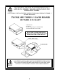
1ST PRINTING
JAN.- 1998
TM
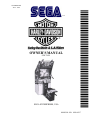
OWNER’S MANUAL
STD TYPE
SEGA ENTERPRISES, USA
MANUAL NO. 4200-6367
Warranty
Your new Sega Product is covered for a period of 90 days from the date of shipment. This certifies
that the Printed Circuit Boards, Power Supplies and Monitor are to be free of defects in workmanship or materials under normal operating conditions. This also certifies that all Interactive Control
Assemblies are to be free from defects in workmanship and materials under normal operating conditions. No other product in this machine is hereby covered.
Sellers sole liability in the event a warranted part described above fails shall be, at its option, to
replace or repair the defective part during the warranty period. For Warranty claims, contact your
Sega Distributor.
Should the Seller determine, by inspection that the product was caused by Accident, Misuse, Neglect, Alteration, Improper Repair, Installation or Testing, the warranty offered will be null and void.
Under no circumstances is the Seller responsible for any loss of profits, loss of use, or other damages.
This shall be the exclusive written Warranty of the original purchaser expressed in lieu of all other
warranties expressed or implied. Under no circumstance shall it extend beyond the period of time
listed above.
TABLE OF CONTENTS
INTRODUCTION OF THE OWNERS MANUAL
GENERAL PRECAUTIONS
1. PRECAUTIONS TO BE HEEDED FOR OPERATION
2. NAME OF PARTS
3. ACCESSORIES
4. ASSEMBLY AND INSTALLATION
5. PRECAUTIONS TO BE HEEDED WHEN MOVING MACHINE
6. CONTENTS OF GAME
7. EXPLANATION OF TEST AND DATA DISPLAY
7-1 POWER SUPPLY UNIT AND COIN METER
7-2 TEST MODE
7-3 MEMORY TEST
7-4 VIDEO MEMORY TEST
7-5 BOUNDRY TEST
7-6 INPUT TEST
7-7 OUTPUT TEST
7-8 SOUND TEST
7-9 C.R.T. TEST
7-10 GAME ASSIGNMENTS
7-11 COIN ASSIGNMENTS
7-12 REAL TIME CLOCK TEST
7-13 VOLUME SETTING
7-14 NETWORK ASSIGNMENTS
7-15 BOOKKEEPING
7-16 BACKUP DATA CLEAR
8. HANDLEBAR
8-1 ADJUSTING/REPLACING THE FRONT BRAKE VOLUME
8-2 ADJUSTING/REPLACING THE ACCELERATOR VOLUME
8-3 ADJUSTING/REPLACING THE HANDLE BAR VOLUME
8-4 GREASING
9. FOOT BRAKE MECHA
9-1 ADJUSTING AND REPLACING THE VOLUME
9-2 GREASING
10. COIN SELECTOR
11. MONITOR
12. REPLACEMENT OF FLUORESCENT LAMP AND LAMPS
12-1 REPLACEMENT OF FLUORESCENT LAMP
12-2 REPLACEMENT OF LAMPS
13. PERIODIC INSPECTION TABLE
14. TROUBLESHOOTING
14-1 REPLACEMENT OF FUSES
15. GAME BOARD
15-1 REMOVING THE IC BOARD
15-2 COMPOSITION OF THE GAME BOARD
16. COMMUNICATION PLAY
16-1 INSTALLATION PRECAUTIONS
16-2 CONNECTING THE COMMUNICATION CABLES
16-3 SETTING FOR COMMUNICATION PLAY
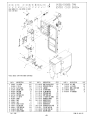
17. DESIGN RELATED PARTS
18. PARTS LIST
19. WIRING DIAGRAMS
1
2~3
4~5
6
7~8
9~14
15
16~18
19~30
20
21
21
22
22
23
23
24
24
25
26~28
29
29
29
30
30
31
31
32
33~36
37
38
38~39
40
41~43
44~46
47~48
47
48
49
50
51
52
52~53
54
55~65
55
55~63
64~65
66
67~94
XXX
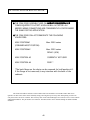
SPECIFICATIONS
Installation space:
65 in.(L) x 31 in.(W)
Height:
78 in.
Weight:
Approx. 397 lbs.
Power maximum current:
5 Amp AC 120V 60 Hz
MONITOR:
29” INCH COLR MONITOR
INTRODUCTION OF THE OWNERS MANUAL
SEGA ENTERPRISES, LTD., has for more than 30 years been supplying various innovative and
popular amusement products to the world market. This Owners Manual is intended to provide
detailed descriptions together with all the necessary installation, game settings and parts ordering
information related to the HARLEY DAVIDSON U/R, a new SEGA product.
This manual is intended for those who have knowledge of electricity and technical expertise, especially in ICs, CRTs, microprocessors, and circuit boards. Read this manual carefully to acquire
sufficient knowledge before working on the machine. Should there be a malfunction, non-technical
personnel should under no circumstances touch the interior system. Should the need arise, contact
our main office, or the closest branch office listed below.
SEGA ENTERPRISES, INC. (USA)
Customer Service
45133 Industrial Drive
Fremont, CA 94538
Phone 650-802-1750
Fax 650-802-1754
7:30 am - 4:00 pm, Pacific Standard Time
Monday thru Friday
1
General Precautions
Follow Instructions: All operating and use instructions should be followed.
Attachments: Do not use attachments not recommended by the product manufacturer as they may cause hazards.
Accessories: Do not place this product on an unstable cart, stand, tripod, bracket, or table. The product may fall,
causing serious injury to a child or adult, and serious damage to the product. Use only with a cart, stand, tripod, bracket, or
table recommended by the manufacturer, or sold with the product. Any mounting of the product should follow the
manufacturer’s instructions, and should use only mounting accessories recommended by the manufacturer.
Moving the Product: This product should be moved with care. Quick stops, excessive force, and uneven surfaces
may cause the product to overturn.
Ventilation: Slots and openings in the cabinet are provided for ventilation, to ensure reliable operation of the product
and to protect it from overheating; these openings must not be blocked or covered. The openings should never be blocked
by placing the product in a built-in installation such as a bookcase or rack unless proper ventilation is provided or the
manufacturer’s instructions have been adhered to.
Power Sources: This product should be operated only from the type of power source indicated on the marking label.
If you are not sure of the type of power supply to your location, consult your local power company. For products intended
to operate from battery power or other sources, refer to the operating instructions.
Grounding or Polarization: This product is equipped with a three-wire grounding-type plug, a plug having a third
(grounding) pin. This plug will only fit into a grounding-type power outlet. This is a safety feature. If you are unable to
insert the plug into the outlet, contact your electrician to replace your obsolete outlet. Do not defeat the safety purpose of the
grounding-type plug.
Power Cord Protection: Power-supply cords should be routed so that they are not likely to be walked on or pinched
by items placed upon or against them, paying particular attention to cords at plugs, convenience receptacles, and the point
where they exit from the product.
Overloading: Do not overload wall outlets, extension cords, or integral convenience receptacles as this can result in
a risk of fire or electric shock.
Object and Liquid Entry: Never push objects of any kind into this product through openings as they may touch
dangerous voltage points or short-out parts that could result in a fire or electric shock. Never spill liquid of any kind on the
product.
Servicing: Do not attempt to service this product yourself as opening or removing covers may expose you to dangerous voltage or other hazards. Refer all servicing to qualified service personnel.
Damage Requiring Service: Unplug this product from the wall outlet and refer servicing to qualified service personnel under the following conditions:
a) If the power cord or plug is damaged;
b) If liquid has been spilled, or objects have fallen into the product;
c) If the product has been exposed to rain or water;
d) If the product does not operate normally when following the operating instructions. Adjust only those controls that
are explained in the operating instructions. An improper adjustment of other controls may result in damage and will
often require extensive work by a qualified technician to restore the product to its normal operation;
e) If the product has been dropped or damaged in any way;
f) When the product exhibits a distinct change in performance; this indicates a need for service.
Replacement Parts: When replacement parts are required, be sure the service technician has used replacements parts
specified by the manufacturer or that have the same characteristics as the original part. Unauthorized substitutions may
result in fire, electric shock, or other hazards.
2
Safety Check: Upon completion of any service or repairs to this product, ask the service technician to perform safety
checks to determine that the product is in proper operating condition.
Heat: The product should be situated away from heat sources such as radiators, heat registers, stoves, or other products (including amplifiers) that produce heat.
Lithium Battery- Dispose of batteries only in accordance with the battery manufacturer’s recommendations. Do not dispose in an open flame condition, since the battery may explode.
Cleaning: When cleaning the monitor glass, use water or glass cleaner and a soft cloth. Do not apply chemicals such
as benzine, thinner, etc.
Location: This an indoor game machine, DO NOT install it outside. To ensure proper usage, avoid installing indoors
in the places mentioned below:
• Places subject to rain/water leakage, or condensation due to humidity;
• In close proximity to a potential wet area;
• Locations receiving direct sunlight;
• Places close to heating units or hot air;
•In the vicinity of highly inflammable/volatile chemicals or hazardous matter;
• On sloped surfaces;
• In the vicinity of emergency response facilities such as fire exits and fire extinguishers;
• Places subject to any type of violent impact;
• Dusty places.
INSTALLATION PRECAUTIONS
• Verify the amperage of the branch circuit outlet before plugging in the power plug. Do not overload the circuit.
• Avoid using an extension cord. If one is required, use an extension cord of type SJT, 16/3 AWG
rated min. 120 VAC, 7A.
• Moving this unit requires a minimum clearance (of doors, etc.) of 32” (W) by 77” (H).
• For the operation of this machine, secure a minimum area of 32” (W) by 42”(D).
REGULATORY APPROVALS
This game has been tested and found to comply with the Federal Communications Commission Rules.
This device complies with Part 15 of the FCC Rules. Operation is subject to the following two conditions: (1) This
device may not cause harmful interference, and (2) this device must accept any interference received, including interference
that may cause undesired operation.
This game has been tested and listed by Underwriters Laboratories, Inc., to ANSI/UL22.
LISTED
UL
5K92
®
AMUSEMENT MACHINE
3
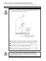
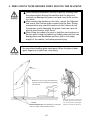
1 . PRECAUTIONS TO BE HEEDED FOR OPERATION
In order to prevent accidents, be sure to comply with the following points before and during operation.
PRECAUTIONS TO BE HEEDED FOR OPERATION BEFORE STARTING THE OPERATION
In order to avoid accidents, check the following before starting the operation:
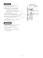
Check if all of the adjusters are in contact with the surface. If they are not,
the cabinet can move and cause an accident.
Ensure that all of the Adjusters
are in contact with the floor.
Do not climb on the product. Climbing on the product can cause falling
down accidents. To check the top portion of the product, use a step.
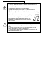
To avoid electric shock, check to see if door & cover parts are 508.5
To avoid electric shock, short circuit and or parts damage, do not put the
following items on or in the periphery of the product:
Flower vases, flower pots, cups, water tanks, cosmetics, and receptacles/
containers/vessels containing chemicals and water.
To avoid injury, be sure to provide sufficient space by considering the
potentially crowded situation at the installation location. Insufficient installation space can cause the player to come into contact with or hit others
and result in injury or trouble.
4
PRECAUTIONS TO BE HEEDED DURING OPERATION
To avoid injury and accidents, those who fall under the following catagories are not
allowed to play the game:
* Intoxidated persons
* Pregnant women or those in the likelyhood od pregnancy.
* Those who need assistasnce such as the use of an apparatus when walking.
* Those who have high blood pressure or heart problems.
* Those who have experienced muscle convulsion or loss of consciousness when playing
video games, etc.
* Persons susceptible to motion sickness.
* Persons whose acts runs counter to the products warning displays.
* Instruct those who wear high-heeled shoes to refrain from
playing the game by explaining that playing the game with highheeled showes is very dangerous and likely to cause a potentially
hazardous situation.
To avoid electric shock and short circuit, do not allow customers to put hands and
fingers or extraneous matter in openings of the product or small openings in or around
doors.
To avoid falling down and injury resulting from falling down, immediatly stop the
customer’s leaning against or climbing on the product, etc.
To avoid electric shock and short circuit, do not allow the customers to unplug the
power plug without a justifiable reason.
5
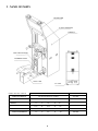
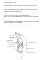
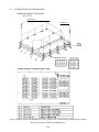
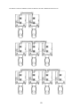
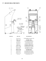
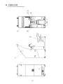
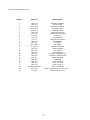
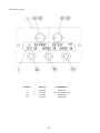
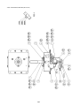
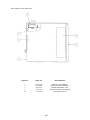
2 . NAME OF PARTS
BILLBOARD
29 INCH MONITOR
CABINET
COIN CHUTE DOOR
CASHBOX DOOR
SEAT CABI
AC UNIT
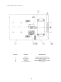
GAME SPECIFICATIONS
WIDTH
SEAT CABI
WHEN ASSEMBLED
HEIGHT
WEIGHT
475 LBS.
All measurements are in inches
DURING SHIPPING
CABINET
LENGTH
X
38”
X
13.5”
X
45.5”
X
25”
49 LBS.
31”
X
65”
X
78”
400 LBS.
6
78”
350 LBS.
31”
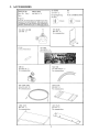
3 . ACCESSORIES
7
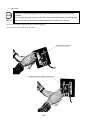
THE SHIPMENT METHOD DESCRIBED BELOW ONLY
APPLIES TO ‘MODEL 3’ BOARDS CONTAINED IN THE
FOLLOWING GAMES:
LOST WORLD, VIRTUA FIGHTER 3, SUPER GT, SEGA BASS FISHING, STRIKER 2
HARLEY DAVIDSON
!!NEVER SHIP MODEL 3 GAME BOARDS
OUTSIDE OF CAGE!!
CARTON BOX
601-8928 (1)
Used for transporting the GAME BOARD.
{SUPPLIED WITH YOUR GAME}
DO NOT SHIP GAME BOARD WITHOUT
THIS BOX AS IT MAY DAMAGE THE GAME
BOARD AND VOID YOUR WARRANTY.
“CHECK SIDE” Display
FILTER BOARD
NO OTHER GAMES BOARDS ARE TO BE SHIPPED IN THE CAGE AS
THEY MAY BE DAMAGED BEYOND REPAIR. PLEASE SHIP THEM
WITHOUT CAGE PROPERLY PROTECTED DURING SHIPPING.
8
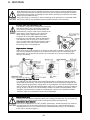
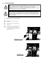
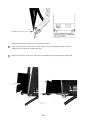
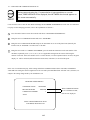
4 . ASSEMBLING AND INSTALLATION
Assembling should be performed as per this manual. Since this is a
complex machine, erroneous assembling may cause damage to the
machine, or malfunctioning to occur.
When assembling, be sure to perform work by plural persons.
Depending on the assembly work, there are some cases in which
performing the work by a single person can cause personal injury or
parts damage.
When carrying out the assembly work, follow the procedure in the following 7-item sequence:
1
ASSY OFCABINET
2
SECURING IN PLACE (ADJUSTER ADJUSTMENT)
3
POWER SUPPLY
4
ASSEMBLING CHECK
Note that the tools such as a phillips screwdriver and wrench for M16 hexagon bolt w/24 mm width
across flats are required for the assembly work.
1
ASSY OF CABINET
Ensure that the connectors are accurately connected. Incomplete
connections can cause electrical shock or short circuit. Be careful
not to damage wirings. Damaged wiring can cause short circuit or
electrical shock.
To perform work safely and securely, be sure to prepare a step
which is in a secure and stable condition. Not using a step or using
an unstable step can cause a violent falling down accident.
9
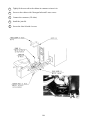
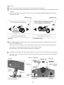
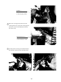
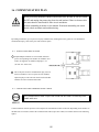
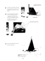
1
Tightly fit the seat cabi to the cabinet in a manner to insert it in.
2
Secure to the cabinet with 2 hexagon bolts and 2 truss screws.
3
Connect the connector. (2P white)
4
Install the joint lid.
5
Secure the Joint lid with 4 screws.
10
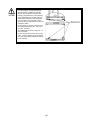
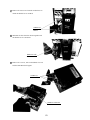
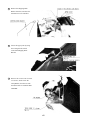
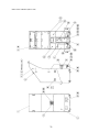
2
SECURING IN PLACE (ADJUSTER ADJUSTMENT)
Be sure to have all the Adjusters make contact with the surface. Unless the Adjusters come into contact with the surface, the Cabinet
can move of itself, causing an accident.
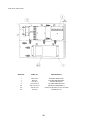
This machine has 8 each of casters and adjusters (shown below). When the installation position is determined, cause
the adjusters to come into contact with the floor directly, make adjustments in a manner so that the casters will be
raised approximately 5mm. from the floor and make sure that the machine position is level.
CASTERS
1
Move the machine to the installation position.
2
Cause all of the leg adjusters to make contact
with the floor. By using a wrench, make
adjustments in the height of the leg adjusters to
ensure that the machine's position is level.
3
After making adjustments, fasten the leg
adjuster nut upward and secure the height of the
leg adjuster.
ADJUSTERS
4
BOTTOM VIEW
Depending on the floor surface status of the installation location, the Rear Cabinet may move of itself. As
shown, the NON-SLIP SHEET is attached to the back side of the CAUTION MAT. Ensure that the Adjuster is
installed in the manner to match the position of NON-SLIP SHEET
5
After making adjustments, fasten the adjuster nut upwards and secure the height of the adjuster
11
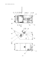
3
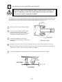
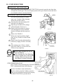
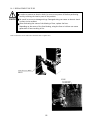
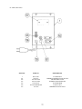
POWER SUPPLY
Ensure that the power cord is not exposed on the surface (passage,
etc.). If exposed, they can be caught and are susceptible to damage.
If damaged, the cord can cause an electric shock or short circuit.
Ensure that the wiring position is not in the customer's passage way
or the wiring has protective covering.
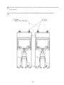
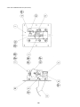
The AC unit is mounted on the rear side of the cabinet . The AC Unit incorporates the Main SW, Earth Terminal and
Inlet. Firmly insert the Power Plug into the Socket Outlet and the other side of the plug to the Inlet. Turn the Main SW
ON to turn power ON.
1
2
Ensure that the Main SW is OFF.
Connect the Power cord to the Outlet
Socket. Ensure power cord is not in
customer’s passage way or wiring has
protective covering.
AC
BRACKET
FUSE
MAIN SW
LINE STRAIN RELIEF
12
BINDING POST NOT USED
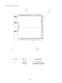
4
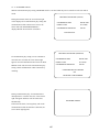
ASSEMBLING CHECK
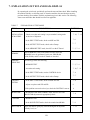
The TEST MENU allows for each part of the cabinet to be checked, the Monitor to be adjusted, and the coin and
game related various functions to be performed.
CPU ROM TEST
GOOD
GOOD
GOOD
GOOD
GOOD
GOOD
GOOD
GOOD
GOOD
GOOD
GOOD
GOOD
GOOD
GOOD
GOOD
GOOD
(CROM03 MASK)
(CROM02 MASK)
(CROM01 MASK)
(CROM00 MASK)
(CROM13 MASK)
(CROM12 MASK)
(CROM11 MASK)
(CROM10 MASK)
(CROM33 EPROM)
(CROM32 EPROM)
(CROM31 EPROM)
(CROM30 EPROM)
(CROM3 EPROM)
(CROM2 EPROM)
(CROM1 EPROM)
(CROM0 EPROM)
IC.1
IC.2
IC.3
IC.4
IC.5
IC.6
IC.7
IC.8
IC.9
IC.10
IC.11
IC.12
IC.13
IC.14
IC.15
IC.16
*****
*****
*****
*****
*****
*****
*****
*****
*****
*****
*****
*****
*****
*****
*****
*****
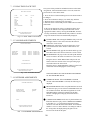
Selecting the MEMORY TEST on the test mode menu screen
causes the on-board memory to be tested automatically. The
game board is satisfactory if the display beside each IC No.
shows GOOD.
PRESS TEST BUTTON TO EXIT
INPUT TEST
HANDLEBAR
THROTTLE
FRONT BRAKE
REAR BRAKE
OFF
OFF
OFF
OFF
VIEW CHANGE
MUSIC SELECT
SHIFT UP
SHIFT DOWN
OFF
OFF
OFF
OFF
START
OFF
COIN #1
OFF
SERVICE-SW
TEST-SW
OFF
OFF
Selecting the INPUT TEST on the menu screen in the test
mode to display the screen on which each SW and Volume is
tested. Press each switch. (To check the Coin SW, insert a
Coin from the inlet with the Coin Chute Door being opened.)
If the display beside each switch is ON, the switch and wiring
connection are satisfactory. Check the display of each Volume
value. The Volume could have an irregularity caused by
differences between machines and vibration during transportation. Set the Volume values by referring to Section ?
PRESS TEST BUTTON TO EXIT
OUTPUT TEST
START
LAMP
OFF
VIEW CHANGE
LAMP
OFF
MUSIC SELECT
LAMP
OFF
RACE READER
LAMP
OFF
In the output test mode, carry out lamp test to ascertain that
each lamp lights up satisfactorily.
>EXIT
SELECT WITH SERVICE BUTTON
PRESS TEST BUTTON TO EXIT
13
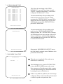
SOUND TEST
NO
:
(0)
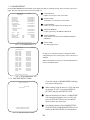
In the TEST mode, selecting SOUND TEST causes the
screen, on which sound related BD and wiring connections are tested, to be displayed. be sure to check if the
sound is satisfactorily emitted from each of speaker and
the sound volume is appropriate.
>EXIT
SELECT WITH SERVICE BUTTON
PRESS TEST BUTTON TO EXIT
C.R.T. TEST 1/2
123456789012345678901234567890121234567890123
123456789012345678901234567890121234567890123
123456789012345678901234567890121234567890123
123456789012345678901234567890121234567890123
123456789012345678901234567890121234567890123
123456789012345678901234567890121234567890123
123456789012345678901234567890121234567890123
123456789012345678901234567890121234567890123
123456789012345678901234567890121234567890123
RED
123456789012345678901234567890121234567890123
123456789012345678901234567890121234567
123456789012345678901234567890121234567890123
123456789012345678901234567890121234567
123456789012345678901234567890121234567
123456789012345678901234567890121234567
123456789012345678901234567890121234567
123456789012345678901234567890121234567
123456789012345678901234567890121234567
GREEN
123456789012345678901234567890121234567
123456789012345678901234567890121234567
123456789012345678901234567890121234567
123456789012345678901234567890121234567
12345678901234567890123456789
12345678901234567890123456789
12345678901234567890123456789
12345678901234567890123456789
BLUE
12345678901234567890123456789
12345678901234567890123456789
12345678901234567890123456789
12345678901234567890123456789
In the TEST mode menu, selecting C.R.T. TEST allows the
screen (on which the projector is tested) to be displayed.
Although the projector adjustments have been made at the
same time of shipment from the factory, color deviation,
etc., may occur due to the effect caused by geomagnitism,
the location building’s steel frames and other game machines in the periphery. By watching the test mode screen,
make judgement as to whether an adjustment is needed. If it
is neccessary, adjust the projector by refering to Section 9.
WHITE
PRESS TEST BUTTON TO CONTINUE
1234567890123456789012345678
1234567890123456789012345678
1234567890123456789012345678
1234567890123456789012345678
1234567890123456789012345678
1234567890123456789012345678
1234567890123456789012345678
1234567890123456789012345678
1234567890123456789012345678
1234567890123456789012345678
1234567890123456789012345678
1234567890123456789012345678
1234567890123456789012345678
1234567890123456789012345678
1234567890123456789012345678
1234567890123456789012345678
1234567890123456789012345678
1234567890123456789012345678
1234567890123456789012345678
1234567890123456789012345678
1234567890123456789012345678
1234567890123456789012345678
1234567890123456789012345678
1234567890123456789012345678
1234567890123456789012345678
C.R.T. TEST 2/2
PRESS TEST BUTTON TO CONTINUE
Perform the above inspections also at the time of monthly inspection.
14
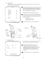
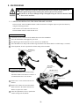
5 . PRECATIONS TO BE HEEDED WHEN MOVING THE MACHINE
When moving the machine, be sure to pull out the plug from
the power supply. Moving the machine with the plug as is
inserted can damage the power cord and cause a fire or electric shock.
When moving the machine on the floor, retract the Adjusters
and ensure that Casters make contact with the floor. During
transportation, pay careful attention so that Casters do not
tread power cords. Damaging the power cords can cause an
electric shock and/or short circuit.
When lifting the cabinet, be sure to hold the catch portions or
bottom part. Lifting the cabinet by holding other portions can
damage parts and installation portions, due to the empty
weight of the cabinet, and cause personal injury.
Use care when handling glass made parts. When the glass is damaged, fragments of glass can cause injury
GRIP
Where there steps (or step-like differences
in grade), move the machine by seperating
into each unit.
CASTER
On level surfaces, move the machine by causing the
casters to make contact with the surfaces.
15
Pushing the glass made or plastic parts
can damage the parts and cause injury.
Also, moving machine by holding the
handlebar can damage the handle bar.
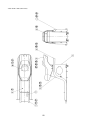
6 . CONTENTS OF GAME
The following are operations and responses obtained when the machine functions satisfactorily. Any functioning
different fromt he following may have been caused by a certain fault. Immediately investigate and eliminate the cause
of the malfunctioning to ensure satisfacory operation. The explanation herein mainly refer to the case where the game
machine is used independently. In communications play, some points may differ fromthe following explanations.
When energized, the Billboard’s fluorescent lamp is always lit.
During ADVERTISE (in the status a coin(s) is not inserted), the contents of game and HOW TO PLAY, etc., are audiovisually explained.
The status of the on-tank 3 buttons will change to and from lighting up/flashing/lights out.
Although the Start button is unlit during ADVERTISE, it blinks if even one coin is inserted, and is always lit duriong
game play.
The View Change button and Music Select button are unlit during ADVERTISE and lit when the Select Mode is
displayed. During Game, the flash alternately.
The two lamps of the Billboard flash during ADVERTISE and Select Mode display, light up during game and flash for
approximately 3 seconds at the time of passing the checkpoint.
In case of communication play, the lamps light up during game, flash for approximately 3 seconds when passing the
chackpoint (in top posistion), and light out for 3 seconds when passing the checkpoint (in the second position or lower).
LAMP
BILLBOARD
SHIFT UP button
SHIFT DOWN button
FRONT BRAKE LEVER
START button
VIEW CHANGE button
ACCELERATOR
COIN INLET
MUSIC SELECT button
REAR BRAKE PEDAL
16
1
Be seated.
2
Insert coin(s). When one play worth of coin(s) is inserted, the Select mode appears.
3
Select in order of BIKE and TRANSMISSION. Turn the handlebar to select and turn the ACCELORATOR GRIP
to decide.
When the Select Mode is displayed, countdown starts. At count 0, BIKE TRANSMISSION being selected are
automatically decided.
4
When TRANSMISSION is decided, the race starts. The checkpoint (desination) is displayed on the screen, and
Time Limit countdown starts.
At the same time the race starts, the View Change button and Music Select button alternately light up/light out.
Pressing the View Change button changes the View point in the game mode.
Pressing the Music Select button changes the BGM (background music).
5
The distance to the checkpoint is displayed onthe upper left section of the screen. the remaining time is indicated
on the upper center, score points on the upper right, navigation window(map) on the lower left, and speedometer
on the lower right.
17
6
Run towards the checkpoint by judging the route from the arrow and the NAVIGATION WINDOW. Passing the
checkpoint within the time limit results in a Stage Clear. The time limit is extended and the next checkpoint is
displayed.
7
If the player fails to pass the checkpoint within the time limit, the game is over.
8
Passing all of the checkpoints results in a Game Clear. The successful player can see the ending mode.
9
After a Game Over, the accomplishment results are displayed on the map.
10
If the player scores high points, the Name Entry mode appears. Turn the Handlebar, select character, and turn the
Accelorator Grip to register intial, etc.
NOTE 1:
Setting change can be made to no sound output during ADVERTISE.
NOTE 2:
In the case where several machines are linked together for communication play, the bike appearing first in the Select
Mode is predetermined by the number of each cabinet set for the communication play.
NOTE 3:
The setting of the number of checkpoints required for game clear is changeable.
KNACK OF GAME PLAY
To make full use of bike characteristics;
Each of the 5 types of bike has specific characteristics. High points can be earned by fully utilizing the bike
charcteristics and selecting the type which suites best for the player.
To memorize the courses;
The player will surely acomplish a game clear by selecting the course on which he can make full use of the bike
characteristics instead of relying on the map and arrow.
18
7 . EXPLANATION OF TEST AND DATA DISPLAY
By operating the switch unit, periodically perform the tests and data check. When installing
the machine initially or collecting cash, or when the machine does not function correctly,
perform checking in accordance with the explanations given in this section. The following
shows tests and modes that should be utilized as applicable.
TABLE 7
EXPLANATION OF TEST MODE
ITEMS
DESCRIPTION
SECTIONS
When the machine is installed, perform the following:
INSTALLATION 1. Check to see that each setting is as per standard setting made
at the time of shipment.
OF MACHINE
MEMORY
PERIODIC
SERVICING
7 - 10, 7 - 11
2. In the INPUT TEST mode, check each SW and VR.
7-6
3. In the OUTPUT TEST mode, check each of lamps.
7-7
4. In the MEMORY TEST mode, check ICs on the IC Board.
7 - 3, 7 - 4
Choose MEMORY TEST in the MENU mode to allow the
MEMORY test to be performed. In this test, PROGRAM
RAMs, ROMs, and ICs on the IC Board are checked.
Periodically perform the following:
1. MEMORY TEST
7 - 3, 7 - 4
2. Ascertain each setting.
7 - 10, 7 - l1
3. In the INPUT TEST mode, test the CONTROL device
7-6
4. In the OUTPUT TEST mode, check each of lamps.
7-7
1. In the INPUT TEST mode, check each SW and VR.
7-6
2. Adjust or replace each SW and VR.
8
3.If the problem can not be solved yet, check the CONTROL’s moves.
8
PROJECTOR
In the PROJECTOR ADJUSTMENT mode, check to see if the
PROJECTOR adjustment is appropriately made.
7-9
IC BOARD
1. MEMORY TEST
CONTROL
SYSTEM
DATA CHECK
2. In the SOUND TEST mode, check the sound related ROMs.
7-8
Check such data as game play time and histogram to adjust the
difficulty level, etc
7 - 15
19
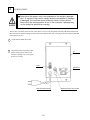
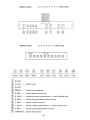
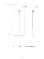
7 - 1 SWITCH UNIT AND COIN METER
Never touch places other than those specified. Touching places not
specified can cause electric shock and short circuit.
Adjust to the optimum sound volume by considering the environmental
requirements of the installation location.
If the COIN METER and the game board are electrically disconnected,
game play is not possible.
Open COIN CHUTE DOOR, and the switch unit shown appears. The function of each switch is as follows:
SWITCH UNIT
1
SOUND VOLUME
Controls the speaker volume
of the right/left speakers on the
coin chute tower.
2
TEST BUTTON (TEST SW)
For the handling of the TEST BUTTON,
refer to the section on test mode.
3
SERVICE BUTTON (SERVICE SW)
Gives credits without registering on the coin
meter.
VOL. FRONT
VOL. SEAT
TEST
SERVICE
20
DEMAG. SW.
7 - 2 TEST MODE
This mainly checks if the operation of the game BD is accurate, and allows for COIN
ASSIGNMENTS/GAME ASSIGNMENTS setting and Projector adjustments.
TEST MENU
CPU MEMORY TEST
1
Push the TEST BUTTON to cause the following TEST MENU to appear:
2
By pushing the SERVICE BUTTON, bring the
“>” mark to the desired item and press the
TEST BUTTON. This will select the item’s
test.
3
After the test is complete, move the “>” mark
to “EXIT” and press the TEST BUTTON to
return to game mode.
VIDEO MEMORYTEST
BOUNDRY SCAN TEST
INPUT TEST
OUTPUT TEST
SOUND TEST
C.R.T. TEST
GAME ASSIGNMENTS
COIN ASSIGNMNETS
NETWORK ASSIGNMENTS
VOLUME ADJUSTMENTS
REAL TIME CLOCK TEST
BOOKKEEPING
BACKUP DATA CLEAR
>EXIT
SELECT WITH SERVICE BUTTON
AND PRESS TEST BUTTON
FIG. 7.2 TEST MENU
The Following FIGURES/TABLES show the factory recommended settings.
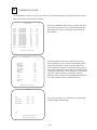
7 - 3 MEMORY TEST
CPU ROM TEST
GOOD
GOOD
GOOD
GOOD
GOOD
GOOD
GOOD
GOOD
GOOD
GOOD
GOOD
GOOD
GOOD
GOOD
GOOD
GOOD
(CROM03 MASK)
(CROM02 MASK)
(CROM01 MASK)
(CROM00 MASK)
(CROM13 MASK)
(CROM12 MASK)
(CROM11 MASK)
(CROM10 MASK)
(CROM33 EPROM)
(CROM32 EPROM)
(CROM31 EPROM)
(CROM30 EPROM)
(CROM3 EPROM)
(CROM2 EPROM)
(CROM1 EPROM)
(CROM0 EPROM)
IC.1
IC.2
IC.3
IC.4
IC.5
IC.6
IC.7
IC.8
IC.9
IC.10
IC.11
IC.12
IC.13
IC.14
IC.15
IC.16
*****
*****
*****
*****
*****
*****
*****
*****
*****
*****
*****
*****
*****
*****
*****
*****
The MEMORY TEST mode is for checking the
on-BD memeory IC functioning.
“GOOD” is displayed for normal ICs and “BAD”
is displayed for abnormal ICs
This test starts immediately after selection from
the menu in the test mode. When in execution, the
“TESTING NOW” message will be displayed at
the lower part to the screen. Press the Test Button
to proceed to CPU RAM TEST
PRESS TEST BUTTON TO EXIT
FIG. 7.3a MEMORY TEST
CPU ROM TEST
GOOD
GOOD
GOOD
GOOD
(SDRAM)
(BACK UP SRAM)
(SCROLL SDRAM)
(SCROLL SDRAM)
IC. 13
IC. 21
IC. 94 or IC.19
IC. 17
IC. 15
IC. 22
IC. 20
IC. 18
Test starts immediately after proceeding to this
mode from CPU ROM TEST. During execution,
the “TESTING NOW” message will be displayed
at the lower part of the screen. When an error
occurs, the ERROR message is shown. After
finising the test, press the TEST button to return
to the menu mode.
PRESS TEST BUTTON TO EXIT
FIG. 7.3b MEMORY TEST
21
7 - 4 VIDEO MEMORY TEST
VIDEO BOARD ROM TEST
GOOD
GOOD
GOOD
GOOD
GOOD
GOOD
GOOD
GOOD
GOOD
GOOD
GOOD
GOOD
GOOD
GOOD
GOOD
GOOD
(VROM01)
(VROM00)
(VROM03)
(VROM02)
(VROM05)
(VROM04)
(VROM07)
(VROM08)
(VROM11)
(VROM10)
(VROM13)
(VROM12)
(VROM15)
(VROM14)
(VROM17)
(VROM16)
IC.26
IC.27
IC.28
IC.29
IC.30
IC.31
IC.32
IC.33
IC.34
IC.35
IC.36
IC.37
IC.38
IC.39
IC.40
IC.41
*****
*****
*****
*****
*****
*****
*****
*****
*****
*****
*****
*****
*****
*****
*****
*****
This allows the functioning of the VIDEO
MEMORY IC’s on the IC board to be checked.
“GOOD” is displayed for normal IC’s and “BAD”
is displayed for abnormal IC’s if any.
Test starts immediately after proceeding to this
mode from the menu in the test mode. During
execution, the “TESTING NOW” message will be
didplayed at the lower portion of the screen. After
fininshing the test, press the TEST BUTTON to
proceed to VIDEO RAM.
PRESS TEST BUTTON TO CONTINUE
FIG. 7.4a VIDEO MEMORY TEST
VIDEO BOARD RAM TEST
PRESS TEST BUTTON TO CONTINUE
FIG. 7.4b VIDEO MEMORY TEST
Test starts immediately after proceeding to this
mode from the VIDEO BOARD ROM TEST.
During execution, the “TESTING NOW” message
will be displayed at the lower portion of the screen.
If staus is satisfactory, nothing will be displayed.
After fininshing the test, press the TEST BUTTON
to return to the menu mode.
Selecting the “BOUNDRY SCAN TEST” causes
the Game board’s testing in terms of hardware to be
performed automatically.
7 - 5 BOUNDRY SCAN TEST
BOUNDRY SCAN TEST
TOTAL ERRORS
0
When the test is completed, if the results are as
shown left, it is satisfacory.
After finishing the test, press the TEST BUTTON
to have the MENU MODE return on the screen.
Next, turn power off and then turn it back on again.
To avoid malfunctioning, have the Board intialized
by turning the power off and then on.
PRESS TEST BUTTON TO EXIT
FIG. 7.5 BOUNDRY SCAN TEST
If there is any hardware problems, an error message
is displayed. Please contact the offices herein stated
or where the product was purchased from.
22
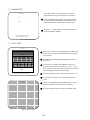
7 - 6 INPUT TEST
When INPUT TEST is selected, the MONITOR will show the following, allowing you to watch the status of
each switch and the value of each V.R.
INPUT TEST
HANDLEBAR
THROTTLE
FRONT BRAKE
REAR BRAKE
OFF
OFF
OFF
OFF
VIEW CHANGE
MUSIC SELECT
SHIFT UP
SHIFT DOWN
OFF
OFF
OFF
OFF
START
OFF
COIN #1
OFF
SERVICE-SW
TEST-SW
OFF
OFF
This test mode displays the status of each switch, button, and
Volu me. When the switch/button corrsponds to the name of
the item is pressed, if OFF changes to ON, it is satisfactory.
When corresponding Volume is operated, if the Volume value
differs in a natural manner, it is satisfactory.
APPROPRIATE VALUE OF TENSION VOLUME
Tension volume values are displayed in hexadecimal numerals within the range of 00H~ffH. If the value does not satisfy
the following limitations, adjust the Volumes gear mesh so as
to meet the requiremnts.
LOWER LIMIT: Over 05H
UPPER LIMIT: Under faH
PRESS TEST BUTTON TO EXIT
Press the test button to return to the menu mode
FIG. 7.6 INPUT TEST
7 - 7 OUTPUT TEST
Choose OUTPUT TEST to cause the following lower screen
to appear. In this test, check the status of each lamp.
OUTPUT TEST
START
LAMP
OFF
VIEW CHANGE
LAMP
OFF
MUSIC SELECT
LAMP
OFF
RACE READER
LAMP
OFF
Pressing the TEST BUTTON causes “ON” to be
displayed and the corresponding lamp lights up.
Pressing the TEST BUTTON again cuases “OFF” to be
displayed and the lamp goes off. The Foot Controller is
locked with the Slide Lock in the ON status, and
Unlocked to become free with the Slide Lock in the
OFF status.
Press the test Button to return to the MENU MODE.
>EXIT
SELECT WITH SERVICE BUTTON
PRESS TEST BUTTON TO EXIT
FIG. 7.7 OUTPUT TEST
23
7 - 8 SOUND TEST
This enables sound used in the game to be checked.
Sound related memory and each speaker are checked.
SOUND TEST
NO
:
(0)
>EXIT
Press the SERVICE BUTTON to increse the number by
one and the sound corresponding to the number will be
emitted. Note that No. 000 does not emit any sound.
Bring the “>” to EXIT and press the TEST BUTTON to
return to the MENU MODE.
SELECT WITH SERVICE BUTTON
PRESS TEST BUTTON TO EXIT
FIG. 7.8 SOUND TEST
7 - 9 C.R.T. TEST
C.R.T. TEST 1/2
12345678901234567890123456789012123456789012
12345678901234567890123456789012123456789012
12345678901234567890123456789012123456789012
12345678901234567890123456789012123456789012
12345678901234567890123456789012123456789012
12345678901234567890123456789012123456789012
12345678901234567890123456789012123456789012
12345678901234567890123456789012123456789012
12345678901234567890123456789012123456789012
12345678901234567890123456789012123456789012
RED
12345678901234567890123456789012123456789012
123456789012345678901234567890121234567
123456789012345678901234567890121234567
123456789012345678901234567890121234567
123456789012345678901234567890121234567
123456789012345678901234567890121234567
123456789012345678901234567890121234567
123456789012345678901234567890121234567
123456789012345678901234567890121234567
GREEN
123456789012345678901234567890121234567
123456789012345678901234567890121234567
123456789012345678901234567890121234567
1234567890123456789012345678
1234567890123456789012345678
1234567890123456789012345678
1234567890123456789012345678
1234567890123456789012345678
BLUE
1234567890123456789012345678
1234567890123456789012345678
1234567890123456789012345678
WHITE
PRESS TEST BUTTON TO CONTINUE
1234567890123456789012345678
1234567890123456789012345678
1234567890123456789012345678
1234567890123456789012345678
1234567890123456789012345678
1234567890123456789012345678
1234567890123456789012345678
1234567890123456789012345678
1234567890123456789012345678
1234567890123456789012345678
1234567890123456789012345678
1234567890123456789012345678
1234567890123456789012345678
1234567890123456789012345678
1234567890123456789012345678
1234567890123456789012345678
1234567890123456789012345678
1234567890123456789012345678
1234567890123456789012345678
1234567890123456789012345678
1234567890123456789012345678
1234567890123456789012345678
1234567890123456789012345678
1234567890123456789012345678
1234567890123456789012345678
Select C.R.T. TEST to cause the MONITOR to display the
screen shown left, allowing MONITOR adjustment status
to be checked.
Periodically check the MONITOR adjustment status on
this screen.
The screen (1/2) enables color adjustment check to be
performed. The color bar of each of the 4 colors, i.e.,red,
green, blue, and white, is the darkest at the extreme left and
becomes brighter towards the extreme right.
Press the TEST BUTTON to shift to the next screen (2/2).
The screen (2/2) allows screen size and distortion to be
tested.
C.R.T. TEST 2/2
Check if the CROSSHATCH FRAME LINE goes out of
the screen and if the crosshatch lines are distorted.
Press the TEST BUTTON to return to the MENU mode.
PRESS TEST BUTTON TO EXIT
FIG. 7.9 C.R.T. TEST
24
7 - 10 GAME ASSIGNMENTS
Selecting the GAME ASSIGNMENTS in the MENU mode causes the present game settings
to be displayed and also the game settings changes (game difficulty, etc.) can be made. Each
item displays the following content.
SETTING CHANGE PROCEDURE
Setting changes cannot be stored unless the TEST BUTTON is pressed
while the arrow is on EXIT.
1
Press the SERVICE BUTTON to move the “>” to the desired item.
2
Choose the desired setting change item by using the TEST BUTTON.
3
To return to the MENU mode, move the arrow to EXIT and press the TEST BUTTON.
GAME ASSIGNMENTS
ADVERTISE SOUND
GAME DIFFICULTY
CABINET TYPE
ON
NORMAL
STANDARD
B.G.M. VOLUME
ENGINE VOLUME
4
8
NUMBER OF STAGES
4
TOURNAMENT MODE
START
MONTH
DAY
YEAR
HOUR
END
MONTH
DAY
YEAR
HOUR
ON
DEC
25
1998
18
DEC
25
1998
18
DURATION DAILY
> EXIT
SELECT WITH SERVICE BUTTON
AND PRESS TEST BUTTTON
ADVERTISE SOUND
Determines wether ADVERTISE SOUND is to
be emitted or not by the setting to ON when
emitting it and to OFF when not emitting it.
GAME DIFFICULTY
Sets the Game Difficulty in 5 catagories from 1 to
8. The greater the number is, the higher the
difficulty level becomes. Alternately it may
display each catagory by name;
Very Easy, Easy, Normal, Hard, Very Hard
B.G.M. VOLUME
BGM Volume Adjustment.
ENGINE VOLUME
Engine Volume adjustment
CABINET TYPE
Set to DELUXE or STANDARD as applicable. Setting to wrong type can causefailure be sure to
set correctly. (i.e. In communication Play Race Leader Lamp does not light up/flash/light out.
The Cabinet appearing in the operation explanation mode differs from the type used.)
TOURNAMENT MODE
During the period set, special bookkeeping for ranking is executed. When set to ON, as shown
above, the date of Tournament Mode Start, the end date of Tournament Mode, and itmes of
bookkeeping periods are displayed. Duration refers to the unit of bookkeeping periods. The
setting can be selected from among DAILY, WEEKLY, BI-WEEKLY, and MONTHLY.Be sure
to set the present time in the Tournament Mode.
The Following FIGURES/TABLES show the factory recommended settings.
25
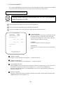
7 - 11 COIN ASSIGNMENTS
The “COIN ASSIGNMENTS” mode permits you to set the start number of credits, as well as the basic numbers
of coins and credits. This mode expresses “how many coins correspond to how many credits.”
SETTING CHANGE PROCEDURE
Setting changes cannot be stored unless the TEST BUTTON is pressed
while the arrow is on EXIT.
1
Press the SERVICE BUTTON to move the arrow to the desired item.
2
Choose the desired setting change item by using the TEST BUTTON.
3
To return to the MENU mode, move the arrow to EXIT and press the TEST BUTTON.
COIN ASSIGNMENTS
COIN CHUTE TYPE
CREDIT TO START
CREDIT TO CONTINUE
COMMON
2 CREDITS
1 CREDIT
COIN/CREDIT SETTING
#1
CHUTE#1
1 COIN
1 CREDIT
CHUTE#2
1 COIN
1 CREDIT
COIN CHUTE TYPE
Sets the combination of the number of COIN CHUTEs and
the number of players as applicable. In the case that the
COIN CHUTE is changed, be sure the setting is made in a
manner meeting the replaced coin chute.
COMMON:
Coins are accepted in common for both players.
MANUAL SETTING
>EXIT
INDIVIDUAL:
Each player uses a coin chute which accepts coins independently.
SELECT WITH SERVICE BUTTON
AND PRESS TEST BUTTON
CREDIT TO START
Number of credits required for starting game (1~5 credits are selected.)
CREDIT TO CONTINUE
Number of credits required for continuing game (1~5 credits are selected.)
COIN/CREDIT SETTING
Sets the CREDITS increase increment per coin insertion. There are 27 setings from #1 to #27, expressed in
XX CREDIT as against XX COINS inserted. (TABLE 7.11a, 7.11b) #27 refers to FREE PLAY.
When the COIN CHUTE TYPE is set to INDIVIDUAL, there are some setting numbers not displayed as
indicated in TABLE 7.11b.
MANUAL SETTING
This allows credit increase setting as against coin insertion to be further set in the manner finer than COIN/
CREDIT SETTING (refer to TABLE 7.11c).
26
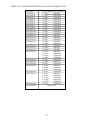
TABLE 7.11a COIN/CREDIT SETTING (COIN CHUTE COMMON TYPE)
SETTING
SETTING #1
SETTING #2
SETTING #3
SETTING #4
SETTING #5
SETTING #6
SETTING #7
SETTING #8
SETTING #9
SETTING #10
SETTING #11
SETTING #12
SETTING #13
SETTING #14
SETTING #15
SETTING #16
SETTING #17
SETTING #18
SETTING #19
SETTING #20
SETTING #21
SETTING #22
SETTING #23
SETTING #24
SETTING #25
SETTING #26
SETTING #27
FUNCTIONING OF CHUTE#1
1 COIN
1 CREDIT
1 COIN
2 CREDITS
1 COIN
3 CREDITS
1 COIN
4 CREDITS
1 COIN
5 CREDITS
1 COIN
2 CREDITS
1 COIN
5 CREDITS
1 COIN
3 CREDITS
1 COIN
4 CREDITS
1 COIN
5 CREDITS
1 COIN
6 CREDITS
2 COINS
1 CREDIT
1 COIN
1 CREDIT
1 COIN
2 CREDITS
1 COIN
1 CREDIT
2 COINS
3 CREDITS
1 COIN
3 CREDITS
3 COINS
1 CREDIT
4 COINS
1 CREDIT
1 COIN
1 CREDIT
2 COINS
2 CREDITS
3 COINS
3 CREDITS
4 COINS
5 CREDITS
1 COIN
5 CREDITS
5 COINS
1 CREDIT
1 COIN
2 CREDITS
2 COINS
1 CREDIT
4 COINS
2 CREDITS
5 COINS
3 CREDITS
1 COIN
3 CREDITS
1 COIN
1 CREDIT
2 COINS
2 CREDITS
3 COINS
3 CREDITS
4 COINS
4 CREDITS
5 COINS
6 CREDITS
1 COIN
1 CREDITS
FREE PLAY
27
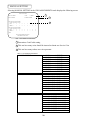
MANUAL SETTING
Selecting MANUAL SETTING in the COIN ASSIGNMENTS mode displays the following screen.
MANUAL SETTING
COIN TO CREDIT
1 COIN
BONUS ADDER
NO BONUS ADDER
1
1 CREDIT
2
COIN CHUTE #1 MULTIPLIER
1 COIN COUNTS AS 1 COIN
COIN
1
2
3
CREDIT 1
2
3
4
4
5
5
6
6
7
7
8
8
9
9
COIN CHUTE #2 MULTIPLIER
1 COIN COUNTS AS 1 COIN
COIN
1
2
3
CREDIT 1
2
3
4
4
5
5
6
6
7
7
8
8
9
9
3
>EXIT
SELECT WITH SERVICE BUTTON
AND PRESS TEST BUTTON
FIG. 7.11b MANUAL SETTING
1 Determines Coin/Credit setting.
2 This sets how many coins should be inserted to obtain one Service Coin.
3 This sets how many tokens one coin represents.
Table 7.11c MANUAL SETTING
COIN TO CREDIT
1 COIN
2 COINS
3 COINS
4 COINS
5 COINS
6 COINS
7 COINS
8 COINS
9 COINS
BONUS ADDER
NO BONUS ADDER
2 COINS GIVE 1 EXTRA COIN
3 COINS GIVE 1 EXTRA COIN
4 COINS GIVE 1 EXTRA COIN
5 COINS GIVE 1 EXTRA COIN
6 COINS GIVE 1 EXTRA COIN
7 COINS GIVE 1 EXTRA COIN
8 COINS GIVE 1 EXTRA COIN
9 COINS GIVE 1 EXTRA COIN
COIN CHUTE MULTIPLIER
1 COIN COUNTS AS 1 COIN
1 COIN COUNTS AS 2 COINS
1 COIN COUNTS AS 3 COINS
1 COIN COUNTS AS 4 COINS
1 COIN COUNTS AS 5 COINS
1 COIN COUNTS AS 6 COINS
1 COIN COUNTS AS 7 COINS
1 COIN COUNTS AS 8 COINS
1 COIN COUNTS AS 9 COINS
28
1 CREDIT
1 CREDIT
1 CREDIT
1 CREDIT
1 CREDIT
1 CREDIT
1 CREDIT
1 CREDIT
1 CREDIT
7 - 12 REAL TIME CLOCK TEST
The system of this product has calandar functions. In the Game
Assignments, if the Tournament mode is set to ON, ensure the
present time is correct in this mode.
REAL TIME CLOCK TEST
25 DEC
1997
THRU
18: 55’30”
BATTERY
O.K.
DAY
MONTH
YEAR
HOUR
MINUTE
SECOND
DAY OF THE WEEK
25
DEC
1997
18
55
30
THU
SET
>EXIT
SELECT WITH SERVICE BUTTON
AND PRESS TEST BUTTON
Fig. 7.12 REAL TIME CLOCK TEST
7 - 13 VOLUME ADJUSTMENTS
VOLUME ADJUSTMENTS
HANDLE BAR
THROTTLE
FRONT BRAKE
REAR BRAKE
MIN (00)
MIN (00)
MIN (00)
MIN (00)
MAX (FF)
MAX (FF)
MAX (FF)
MAX (FF)
NUETRAL (80)
CHECKING (00)
CHECKING (00)
CHECKING (00)
1. Press the Service button and bring arrow to the desired item to
be changed.
2. Press the test button to change year, month, day, and hour.
3. Bring the arrow to SET and press test button.
4. Move the arrow to EXIT and press the TEST button to return to
menu mode.
In the case an appropriate value is not displayed in the input
test mode, the Volume can be adjusted in this mode. Set an
appropriate Volume value by moving the HandleBar, Accelerator Grip, Front Brake, and Rear Brake fully within it’s movable
range. The numeral values are hexadecimally displayed.
HANDLE BAR: After turning the handlebar fully to the left
and right, return it to the cneter and ensure the status in
which force is not exerted.
THROTTLE: After fully moving accelerator grip, let go
your hold and return to the status in which force is not
exerted.
FRONT BRAKE: Fully grip the front brake and let go your
hold, then return to the status in which force is not exerted.
REAR BRAKE: Fully step on the rear brake pedal and then
release to return to the status of which force is not exerted.
Bring the cursor to EXIT WITH SAVE and press the test
button to have the contents of the new input setting registered and return to the menu mode.
Bring the cursor to EXIT WITHOUT SAVE to return to the
menu mode without changing the current settings.
EXIT WITH SAVE
>EXIT WITHOUT SAVE
SELECT WITH SERVICE BUTTON AND
PRESS TEST BUTTON TO EXIT
Fig. 7.13b VOLUME SETTING
THIS TEST MENU ALLOWS FOR THE ADJUSTMENT
OF THE NETWORK SETUP.
7 - 14 NETWORK ASSIGNMENTS
NETWORK ASSIGNMENTS
COMMUNICATION
PRIVILEGE MODE
CABINET ID NUMBER
NETWORK
MASTER
1
>EXIT
SELECT WITH SERVICE BUTTON
PRESS TEST BUTTON TO EXIT
FIG. 7.14 NETWORK ASSSIGNMENTS
COMMUNICATION: Select NETWORK or STAND
ALONE. When NETWORK is selected, the following are
displayed.
PRIVILEGED MODE: In the case plural machines are used
for interactive play, set one of them to MASTER and set the
rest of them to SLAVE. The Game Assignments set to the
MASTER cabinet will also be applied to the SLAVE
cabinets. Changing the settings by the SLAVE units is
ineffective.
CABINET ID NUMBER: In the case of plural machines are
linked for interactive play, set the CABINET ID NUMBER
in the order of 1, 2, 3, and 4 starting from the left most
cabinet as seen from the front of the cabinet. If an identical
number is set to 2 or more cabinets or if settings is made in
the wrong order, the display during the game will be
incorrect. Be careful of this point.
29
7 - 15 BOOKKEEPING
Choosing BOOKKEEPING in the MENU mode displays the data of operating status up to the present are shown on 2
pages. Press the TEST BUTTON to proceed to PAGE 2/2.
BOOKKEEPING
COIN REPORT
COIN CHUTE#*:
Number of coins put in each Coin Chute.
PAGE1/2
COIN CHUTE #1
COIN CHUTE #2
TOTAL COINS
COIN CREDITS
SERVICE CREDITS
TOTAL CREDITS
NUMBER OF GAMES
1 P GAMES
2 P GAMES
NUMBER OF CONTINUE
1 P GAMES
2 P GAMES
XXXXXXXXXXX
XXXXXXXXXXX
XXXXXXXXXXX
XXXXXXXXXXX
XXXXXXXXXXX
XXXXXXXXXXX
TOTAL
TIME
PLAY
TIME
AVERAGE PLAY
LONGEST PLAY
SHORTETEST PLAY
XDXXHXXMXXS
XDXXHXXMXXS
XXMXXS
XXMXXS
XXMXXS
XXXXXXXXXXX
XXXXXXXXXXX
XXXXXXXXXXX
XXXXXXXXXXX
TIME
TIME
TIME
PRESS TEST BUTTON TO CONTINUE
FIG. 7.15a BOOKKEEPING (1/2)
BOOKKEEPING
TIME HISTOGRAM
0M00S ~ 0M29S
0M30S ~ 0M39S
0M40S ~ 0M49S
0M50S ~ 0M59S
1M00S ~ 1M09S
1M10S ~ 1M19S
1M20S ~ 1M29S
1M30S ~ 1M39S
1M40S ~ 1M49S
1M50S ~ 1M59S
4M00S ~ 4M09S
4M10S ~ 4M19S
4M20S ~ 4M29S
4M30S ~ 4M39S
4M40S ~ 4M49S
4M50S ~ 4M59S
5M00S ~
TOTAL COINS:
Total number of activations of Coin Chutes.
COIN CREDITS:
Number of credits registered by inserting coins.
SERVICE CREDITS:
Credits registered by the SERVICE BUTTON.
TOTAL CREDITS:
Total number of credits (COIN CREDITS+SERVICE
CREDITS).
TOTAL TIME:
The total energized time.
PAGE 2/2
XXXXXXXX
XXXXXXXX
XXXXXXXX
XXXXXXXX
XXXXXXXX
XXXXXXXX
XXXXXXXX
XXXXXXXX
XXXXXXXX
XXXXXXXX
XXXXXXXX
XXXXXXXX
XXXXXXXX
XXXXXXXX
XXXXXXXX
XXXXXXXX
XXXXXXXX
On page (2/2), each play frequency is displayed. When
setting difficulty levels, the frequency can be refered to as a
standard.
When in the PAGE 2/2 mode, press the TEST BUTTON to
return to the MENU mode.
PRESS TEST BUTTON TO EXIT
FIG. 7.15b BOOKKEEPING (2/2)
7 - 16 BACKUP DATA CLEAR
Clears the contents of BOOKKEEPING and high
score player ranking entry.
BACKUP DATA CLEAR
YES (CLEAR)
>NO (CANCEL)
When clearing, bring the arrow to “YES” and when
not clearing, to “NO”, by using the SERVICE
BUTTON, and push the TEST BUTTON.
When the data has been cleared, “COMPLETED”
will be displayed. Bring the arrow to “NO” and
press the TEST BUTTON to cause the MENU
mode to return on to the screen.
Note that the contents of the GAME SETTING,
COIN SETTING, and BOARD SETTING are not
affected by BACKUP DATA CLEAR operation.
SELECT WITH SERVICE BUTTON
PRESS TEST BUTTON TO EXIT
FIG. 7.16 BACKUP DATA CLEAR
30
8 . HANDLEBAR
In order to prevent an electric shock and short circuit, be sure to turn power off
before performing work by touching the interior parts of the product.
Be careful so as not to damage wirings. Damaged wiring can cause an electric shock
or short circuit accident.
8 - 1 ADJUSTING/REPLACING THE FRONT BRAKE VOLUME
In the test mode, if the Front Brake Volume’s Value movements are irregular, adjust or replace the Volume by
using the following procedure:
Take out the 4 screws and remove the VR cover.
The Front Brake Volume is inside the VR cover.
VOLUME ADJUSTMENT
1
Loosen the 2 screws which secure the VR bracket to move the VR Bracket.
2
Move the VR Bracket to disengage the gear mesh.
3
By adjusting gear mesh, fasten the 2 screws which secure VR Bracket.
4
Move the Brake Lever fully to the movable range and check if the Volume Shaft’s revolvable range is exceeded.
5
After adjustment, be sure to perform the Volume setting in the Test Mode.
SCREW (4)
M4x8
VOLUME
220-5484
VOLUME ADJUSTMENT
VR BRACKET
Replace the Volume if it is malfunctioning.
Install the Volume in the manner so that 20+/-5
SCREW (2)
is indicated when force is not exerted.
M4x8
1
Remove the 2 screws which secure the VR
Bracket.
2
Remove the Volume Gear from the Volume
Shaft and remove the Volume from the VR
Bracket to replace the volume.
3
After the replacement, be sure to perform the
Volume setting in the Test Mode.
31
8 - 2 ADJUSTING/REPLACING THE ACCELERATOR VOLUME
In the test mode, if the Front Brake Volume’s Value movements are irregular, adjust or replace the Volume by
using the following procedure:
Take out the 4 screws and remove the VR cover.
The Front Brake Volume is inside the VR cover.
VOLUME ADJUSTMENT
1
Loosen the 2 screws which secure the VR
bracket to move the VR Bracket.
2
Move the VR Bracket to disengage the
gear mesh.
3 By adjusting gear mesh, fasten the 2
screws which secure VR Bracket.
4
5
Move the Brake Lever fully to the movable
range and check if the Volume Shaft’s
TRUSS SCREW (4)
revolvable range is exceeded.
M4x8
After adjustment, be sure to perform the
Volume setting in the Test Mode.
ACCELERATOR GRIP
VOLUME ADJUSTMENT
Replace the Volume if it is malfunctioning.
Install the Volume in the manner so that 20+/-5
is indicated when force is not exerted.
VR COVER
1 Remove the 2 screws which secure the VR
Bracket.
2 Remove the Volume Gear from the Volume
Shaft and remove the Volume from the VR
Bracket to replace the volume.
3 After the replacement, be sure to perform the
Volume setting in the Test Mode.
VOLUME
SCREW (1)
ACCELERATOR VR BRACKET
M4x8
32
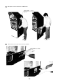
8 - 3 ADJUSTING/REPLACING THE HANDLEBAR VOLUME
In the Test Mode, if the HandleBar Volume’s value movements are irregular, adjust or replace the Volume.
1
Remove the 4 screws.
TRUSS SCREW (4)
M4x8 (black)
CONNECTORS
2 Disconnect the 3 connectors and remove
the mask cover.
When the mask cover is removed, monitor
screen adjustment knob appears.
ADJUSTMENT KNOB
33
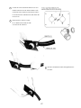
3 Remove the bolt w/hexagon hole and pull out the
handle from the shaft.
Bolt w/hexagon hole
M10x20,
w/flat and spring washers
4
Take out the 3 screws, disconnect the connector inside the tank, and remove the tank.
TRUSS SCREW (3)
CONNECTOR
M4x12, Flat washer
8P YELLOW
34
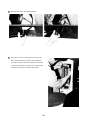
SCREW (1)
M4x8,
w/ flat and spring washers
5 Remove the 4 hexagon nuts which secure the
centering mecha. By viewing the centering mecha
from above, remove the hexagon nuts from the
four corners only.
HEXAGON NUT (4)
M8
w/ flat and spring washers
6 Carefully lift the centering mecha and disconnect
the connector connected to the centering mecha.
35
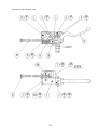
V.R. ADJUSTMENT
Do not touch places other than those specified. Touching placers not specified can
cause an electric shock and /or short circuit accident.
1
Loosen the 2 screws which secure the V.R.
Bracket to move the V.R. Bracket.
2
Move the V.R. Bracket to disengage ADJUST
GEAR mesh and move the V.R. shaft in the
SCREW (2)
manner so that the V.R. shaft cut portion faces
M4x8
V.R. SHAFT
the oppisite side of ADJUST GEAR as shown.
3
ADJUST GEAR
Have the gears meshed and tighten the 2
screws.
4
Carefully turn the Handle Shaft to left/right
and check to ensure the value variation is
GEAR
within the mobile range of the Volume.
5
After finishing adjustments, be sure to perform
V.R. BRACKET
Volume Setting in Test Mode.
V.R. REPLACEMENT
1
SCREW (2)
Take out the 2 screws which secure the Volume
Bracket to remove the Volume Bracket.
M4x8
2
Remove the Volume Gear fromt he V.R. to
replace the V.R.
3
After the replacement, perform Volume Setting
in the Test Mode.
HANDLE V.R.
36
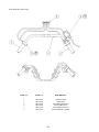
8 - 4 GREASING
Be sure to use the designated grease. Using undesignated grease can cause parts
damage.
Do not apply greasing to places other than those specified. Greasing to undesignated
places can cause malfunctioning and the quanlitative deterioration of parts.
Once every three months, apply greasing to the following places.
For Greasing use Grease Mate (P.No. 090-0066).
GEAR MESH PORTION
(FRONT V.R.)
GEAR MESH PORTION
(ACCELERATOR)
SLIDING FACE OF BRAKE
GEAR MESH PORTION
(FRONT V.R.)
37
9. FOOT BRAKE MECHA
In order to prevent an electric shock and short circuit, be sure to turn power off
before performing work by touching the interior parts of the product.
Be careful so as not to damage wirings. Damaged wiring can cause an electric
shock or short circuit accident.
Do not touch places other than those specified. Touching places not specified can
cause an electric shock or short circuit accident.
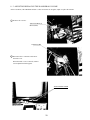
9 - 1 ADJUSTING AND REPLACING THE VOLUME
In the Test Mode, if the Rear Brake’s (Foot Brake’s) volume movements are irregular, adjust or replace the Volume
by using the following procedure.
1
Remove the 6 screws.
2
Disconnect the connector, and remove the Foot Brake Mecha from the cabinet.
TRUSS SCREW (6)
M6x16, chrome
CONNECTOR
WHITE 4P
FOOT BRAKE MECHA
TRUSS SCREW (6)
M6x16, chrome
38
V.R. ADJUSTMENT
SCREW (2) M4x8,
1
w/flat and spring washers
Loosen the 2 screws which secure the V.R.
V.R. SHAFT
Plate to move the V.R. Plate.
2
Move the V.R. Plate to disengage ADJUST
GEAR mesh and move the V.R. shaft and
ensure that when force is not exerted on the
V.R. PLATE
pedal, the cut face of the Volume Shaft faces in
the direction shown.
3
Have the gears meshed and tighten the 2
ADJUST GEAR
screws. At this time, tighten gear backlash.
4
Carefully move pedal fully within the movable
range and check if the Volume range is
exceeded.
5
After finishing adjustments, be sure to perform
Volume Setting in Test Mode.
V.R. REPLACEMENT
1
Take out the 2 screws which secure the Volume
Plate to remove the Volume Plate.
2
Remove the Volume Gear from the V.R. to
replace the V.R.
3
After the replacement, perform Volume Setting
in the Test Mode.
39
9 - 2 GREASING
Be sure to use the designated grease. Using undesignated grease can cause parts
damage.
Do not apply greasing to places other than those specified. Greasing to undesignated
places can cause malfunctioning and the quanlitative deterioration of parts.
Once every three months, apply greasing to the following places.
For Greasing use Grease Mate (P.No. 090-0066).
GEAR MESH PORTION
SLIDING FACE OF SPRING AND SHAFT
40
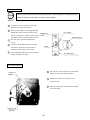
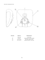
10 . COIN SELECTOR
HANDLING THE COIN JAM
If the coin is not rejected when the REJECT BUTTON is pressed, open the coin chute door
and open the selector gate. After removing the jammed coin, put a normal coin in and check
to see that the selector correctly functions.
CLEANING THE COIN SELECTOR
1
2
3
4
5
6
GATE
The coin selector should be cleaned
once every 3 months. When cleaning,
follow the procedure below:
Turn the power for the machine OFF.
Open the coin chute door.
Open the gate and dust off by using a
soft brush (made of wool, etc.).
Remove and cleen smears by using a
soft cloth dipped in water or diluted
chemical detergent and then squeezed
dry.
Remove the CRADLE.
When removing the retaining ring(Ering), be very careful so as not to bend
the shaft.
Remove stain from the shaft and pillow
portions by wiping off with a soft cloth,
etc.
After wiping as per #5 above, further
apply a dry cloth, etc. to cause the coin
selector to dry completely.
FIG. 9a
CRADLE
FIG.9b
Never apply machine oil, etc. to
the coin selector
After cleaning the Coin Selecting,
Insert a regular coin in the normal
working status and ensure that
the Selector correctly functions.
COIN INSERTION TEST
Once a month, when performing the COIN SW
TEST, simultaneously check the following:
Does the Coin Meter count satisfactorily?
Does the coin drop into the Cashbox correctly?
Is the coin rejected when inserted while keeping
the REJECT BUTTON is pressed down?
Insert a coin
while keeping
the Reject
Button pressed
down and check
if it is
rejected.
COIN METER
FIG. 9c
41
OPTIONAL DOLLAR BILL ACCEPTOR
THE COIN DOOR ASSEMBLY USED ON HARLEY DAVIDSON U/R
COMES EQUIPPED TO ACCEPT A DOLLAR BILL ACCEPTOR. ALL
NEEDED WIRING CONNECTIONS ARE CONVIENENTLY LOCATED INSIDE
THE GAME FOR THIS APPLICATION.
THE COIN DOOR CAN ACCCOMMODATE THE FOLLOWING
VALIDATORS:
HOLE POSITION#1
(FORWARD-MOST POSITION)
Mars 2000 series
HOLE POSITION#2
Mars 2000 series
DBV45 (JCM)
HOLE POSITION #3
CURRENTLY NOT USED
HOLE POSITION #4
DSI01*
*The back flange on the chute can be removed for hold position #4.
If the flange is not removed, it may interfere with the back of the
cabinent.
The frame and cashbox enclosure on this coindoor has been modified to accomodate a Mars 2000 series
upstacker. A 2000 series stacker can be added by simply removing the top two entry door and replacing it with a one
entry door with a cut-out for a stacker. This one entry door can be ordered through Coin Controls or one of Coin Controls
autherized distributors. The part number is 91-4000-01. The Mars stacker can be obtained through an autherized Mars
distibutor.
42
43
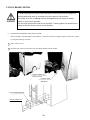
11 . MONITOR
When performing such work as installing and removing the monitor, inserting and disconnecting the external connectors to and from monitor, be sure to disconnect the power connector
(plug) before starting work. Proceeding the work without following this instruction can cause
electric shock of malfunctioning.
Using the monitor by converting it without obtaining a prior permission is not allowed. SEGA
shall not be liable for any malfunctioning and accident caused by said conversion.
Primary side and secondary side
The monitor’s circuit which is divided into the Primary
side and secondary side, is electrically isolated. Do
not touch the primary side and the secondary side
simultaneously. Failing to observe the instruction can
cause electric shock, and this is very dangerous.
When making monitor adjustments, use a nonconductive driver and make adjustment without
touching any other part other than the Adjustment
V.R. and Knob. Also, be sure not to cause a shortcircuit to the Primary side and the Secondary side. If
short-circuited, it can cause electric shock or malfunctioning, which is very dangerous.
High tension Voltage
Some of the parts inside the monitor are subject to high-tension voltage in excess of 20,000
volts and very dangerous. Therefore, do not touch the monitor interior. Should soldering &
paper wastes, etc. be mixed in the monitor, turn the power off so as not to cause malfunctioning or fire hazard.
Connecting the CRT and PCB
For combining the CRT and PCB, use the specified part No. to maintain the status of adjustments made at the factory. The anode of the CRT itself will be accumulitavly charged as time
elapses, generating high tension voltage which is very dangerous. The monitor should be used
with the Chassis, CRT and PCB assembled. When repair, etc. is required at the time of malfunctioning, be sure to send it in an “as assembled” condition. If these are dissassembled, what’s
charged to said high tension voltage can be discharged, cuasing a very hazardous situation.
Therefore, under no circumstances should it be dissasembled.
Static Electricity
Touching the CRT surface sometimes cuases you to slightly feel electricity. this is because the
CRT surfaces are subject to static and will not adversly affect the human body.
Installation and removal
Ensure that the Magnetizer Coil, FBT (Fly-Back Transformer), Anode Lead and Focus Lead are
not positioned close to the sheet metal work’s sharp edges, etc. and avoid damaging the
insulated portions so as no to cause an electric shock and malfunctioning. (For the name of
parts, refer to the above figures.)
44
For the purpose of static prevention,
special coating is applied to the CRT
face of this product. To protect the
coating, pay attention to the following
points. Damaging the coating film can
cause electric shock to the customers.
For the caution to be heeded when
clearing, refer to the Section of Periodic
inspection Table.
Do not apply or rub with a hard item (a
rod with pointed edge, pen, etc.) to or
on C.R.T. surfaces.
Avoid applying stoickers, seals, etc. on
the C.R.T. face.
Do not remove aluminum foils from the
C.R.T. corners. Removing the aluminum
foils can cause static prevention effects
to be lowered.
45
46
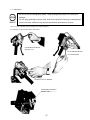
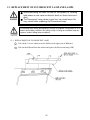
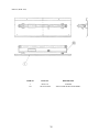
12 . REPLACEMENT OF FLUORESCENT LAMP AND LAMPS
When performing the work, be sure to turn power off. Working
with power on can cause an electric shock or short circuit accident.
The Flourescent Lamp, when it gets hot, can cause burns. Be
very careful when replacing the Fluorescent Lamp.
To perform work safely and securely, be sure to prepare a step which is in a
secure and stable condition. Not using a step or using an unstable step can
cause a violent falling down accidents.
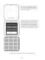
12 -1 REPLACEMENT OF FLUORESCENT LAMP
1
Take off the 3 screws which secure the Holder on the upper part of Billboard.
2
Take out the billboard from the cabinet and replace the fluorescent lamp (20W)
47
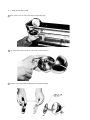
12 - 2 REPLACING THE LAMP
1 Take out the screw to remove the lamp from the lamp body.
2 By using a flat blade screwdriver, remove the 3 inside fasteners.
3 As shown left, dissassmble the lamp parts and replace the lamp.
48
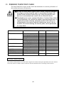
13 . PERIODIC INSPECTION TABLE
The items listed below require periodic check and maintenance to retain the performance of
this machine and ensure safe operation.
Be sure to check once a year to see if Power Cords are damaged,
the plug is securley inserted, dust is accumulated between the
Socket Outlet and the Power Plug, etc. Using the product with
dust as is accumulated can cause a fire or electrical shock.
Periodically once a year, request the place of contact herin stated
or the Distributer, etc. where the product was purchased from, as
regards the interior cleaning. Using the product with dust as is
accumulated in the interior without cleaning can cause a fire or
accident. Note that cleaning the interior parts can be performed
on a pay-basis.
ITEMS
DESCRIPTION
PERIOD
REFERENCE
BIKE MECHA
Volume V.R. inspection
Greasing to gears and springs
Memory Test
Setting Check
SW Volume inspection
Greasing to gears and springs
Check Volume Value.
Check COIN SW
COIN SELECTOR cleaning
Screen cleaning
Check adjustments
Setting check
Cleaning
Inspection and cleaning
Cleaning
Monthly
Monthly
Monthly
Monthly
Monthly
Tri-monthly
Monthly
Monthly
Trimonthly
Weekly
Monthly
Monthly
Annually
7, 8
8
7
7
7, 8
8
7
7
10
11
4, 7, 11
7
see above.
As necessary
see below
BRAKE MECHA
COIN SELECTOR
PROJECTOR
GAME BD
INTERIOR
POWER PLUG
CABINET SURFACES
CLEANING CABINET SURFACES
If the cabinet is badly stained, use a cloth which is dipped in the chemical detergent liquid diluted with water and then
suezzed dry. Do not use thinner, benzine, alcohol or chemical dustcloth as these can damage Cabinet surfaces.
49
14 . TROUBLESHOOTING
Should trouble occur, first check connector connections.
PROBLEMS
CAUSE
COUNTERMEASURES
With Main SW
ON, no activation
Power is not supplied.
Plug in correctly
Power supply/voltage is not correct.
Make sure that power supply/voltage is
correct.
Check fuse. Remove the cause of
overload and replace fuse
AC main fuse causes the
power to be cut off due to momentary
overload.
Operation is
unsatisfactory
Volume Setting Failure
Perform Volume setting
Adjust or replace V.R.
Poor mesh of V.R. gear.
Adjust Gear mesh..
Spring failure due to secular change
of Accelerator and brake mecha.
Replace the Spring.
Irregular sound
emitted from
inside Rear Cabinet
Greasing to gear mesh portion is not
satisfactory, or extraneous matter
mixed in.
Apply greasing or eliminate extraneous
matter.
The color of the
image on PROJ.
screen is incorrect.
Connector connections are defective.
Check the connection for the RGB and
SYNC connectors of the PROJ. TERM.
BD and VPM BUFFER BD.
The image on PROJ.
screen has color
deviation.
Affected by the magnetic field of
installation location.
Make CONVERGENCE adjustment.
(Refer to Section 9.)
No sound is emitted.
Sound Volume adjustment is not
appropriate.
Adjust sound volume. (see Section 6).
Sound BD and speaker are
malfunctioning.
Perform sound test to find and replace
defective parts.(Refer to Section 6).
NETWORK check
will not finish.
Communication cable’s connection
failure.
Perform V.R. setting, Adjustment.
Communication play
is not possible.
Communication cable’s connection
failure.
Communication Play setting is wrong.
Check for Communication cable
disconnection
Correctly set in test mode.
No sound from
Vibration Mecha.
In correct Cabinet Type Setting.
Correct Cabinet Type Setting.
The Fluorescent
lamp does not
light up.
The Fluorescent tube is burnt out.
Replace the Fluorescent tube
(Refer to Section 10).
Shift operation is not
is not satisfactory in
Manual transmission.
Shift SW malfunctioning.
Replace SW
50
14 - 1 REPLACEMENT OF FUSE
In order to prevent an electric shock, be sure to turn power off before performing
work by touching the interior parts of the product.
Be careful so as not to damage wirings. Damaged wiring can cause an electric shock
or short circiut accident
After eliminating the cause of the blowing of fuse, replace the fuse.
Depending on the cause of the fuse blowing, using the fuse as is blown can cause
generation of heat resulting in fire.
Take out the truss screws and remove the back door to replace fuse.
Truss Screw (2) Black
M4x25
FUSE
51
15 . GAME BOARD
In order to prevent an electrical shock, be sure to turn power off before
performing work by touching the interior parts of the product.
Be careful so as not to damage wirings. Damaged wiring can cause an
electric shock or short circuit accident.
Do not expose the Game BD, etc. without a good reason. In this product,
setting changes are made during the test mode. The Game BD need not be
operated. Use the Game BD, etc. as is with the same setting made at the
time of shipment.
15 -1 REMOVING THE GAME BOARD
1
Remove the 2 screws which secure the
Front Door.
2
Unlock and remove the Front Door from
the Cabinet
3
Disconnect all of the connectors connected
to the Shield Case. (Blue 2P, Black 4P,
Black 6P, White 8P, Black 10P, Black 12P,
Red 12P, Blue 12P)
Screw (2)
M4x30, flat washer used
CONNECTOR (8)
52
4 Remove the truss screws fromthe wooden base on
which the Shield Case is mounted.
SCREW (2)
M4x25
5 Withdraw the base from the cabinet together with
the Shield Case as is mounted.
SHIELD CASE
6 Remove the 3 screws, take out the Shield Case Lid
and the Game Board will appear.
SCREW (3)
SHIELD CASE LID
53
15 - 2 COMPOSITION OF GAME BOARD
GAME BD HARLEY DAVIDSON
(833-13325)
SCREW (16)
M3x55, flat and spring washers used
SCREW (1)
M3x35
JUMPER SETTING
NOTE: THIS PICTURE IS FOR REFERENCE ONLY!! UNIT IS NOT TO BE OPENED. EXPOSING THE GAME
BD FOR ANY REASON MAY VOID WARRANTY.
54
16. COMMUNICATION PLAY
Before performing between-cabinets connection work, be sure to turn the Power
SW OFF and unplug the power plug from the wall socket. Failure to observe this
can cause electric shock and/or short circuit accidents.
Perform assembling as shown in this manual. Erroneous assembling can cause
electric shock accidents and malfunctioning.
By linking 4 machines, up to 4 persons can play simultaneously. Although accessory parts are to be installed for
communication play, some of the parts will remain as spares.
16 - 1 INSTALLATION PRECAUTIONS
1
Simplemultiple machines are to be linked, sufficient
power corresponding to the number of machines used
need to be supplied. As standard, amperage is 7A
(AC100~110~120V area).
2
Due to the parts used for communication play, interval
between machines is 20 cm. If parts are not installed,
adjascent players will come nto contact with each other
and this can cause accidents and trouble.
16 - 2 CONNECTING THE COMMUNICATION CABLES
The Communication Cable is optic-fiber made and will break if excessively bent.
Handle with care.
Connect machines with the protective tube and pass the communication cable in the tube. Depending on the number of
machine units to be linked, connect the communication cables (optic-fiber cables) in a manner shown in the following
figures.
55
1
Take out the 2 screws and remove the Back Door.
2
Take out the 4 screws and remove the Fiber Lid Base.
56
3
Loosen the screw and turn the Fiber Lid so as to
install Connector 29 to the Fiber Lid Base. Take
out the nut from Connector 29 and insert Connector 29 into the Fiber Lid Base hole, then fasten the
nut to secure.
4
Insert Protective Tube to Connector 29. With a click sound, the tube
is secured to the connector.
5
Pass the communication cable through the Protective Tube.
57
6
Reinstall Fiber Lid to the original position.
7
Take out the 2 screws, unlock and remove the Front
Door, and the Shield Case appears. the communication cable insertion connector is with the Filter Board
in front of the Shield Case. Take off the Cap from the
connector and insert the communication cable.
58
EXAMPLE OF HOW CABINETS SHOULD BE SET UP FOR COMMUNICATION PLAY
59
Install joint parts used to join interactive play machines together.
8
Loosen the hexagon bolt on the lower rear of the cabinet. Loosen the hexagon bolt onthe side where
machines are to be linked for communication play.
9
Insert the notch portion of the lower joint to the loosened hexagon bolt and retighten the hexagon bolt.
60
10
As in the rear of the cabinet, loosen the
hexagon bolt of the side where the lower
joint in front of the cabinet is to be installed.
11
Insert the Joint Plate’s notch portion
to the loosened hexagon bolt and
retighten the hexagon bolt. At this
time, align the Joint Plate’s hole and
the lower joint’s screw hole, then
retighten the hexagonal bolt.
12
Secure the joint Plate and Lower Joint
with the 2 hexagon bolts.
61
13
Remove the Shipping Hook
Bracket from the side where the
Joint Parts are to be installed.
14
Secure the Upper joint by using
the 2 hexagon bolts which
secured the Shipping Hook
Bracket.
15
Remove the 2 screws out of a total
of 4 screws, which secure the
Lamp Holder, from the rear side
and utilize these to install the POP
HOLDER.
62
16
In the similiar manner shown as on the previous page, connect the communication cable for the other machine and
install joint parts.
17 By using 2-sided tape, install the POP PANEL to the POP HOLDER installed for the adjoining machines.
63
16 - 3 SETTING FOR COMMUNICATION PLAY
During communication play, if communication is interrupted due to a certain
cause, ERROR MESSAGE will be displayed, then NETWORK check mode appears on
the screen automatically.
Cause all of the seats to enter the Test Mode and change the NETWORK ASSIGNMENTS of each seat for communication play. For the Changing procedure, refer to the explanations of Section 7.
1
Press the TEST button to enter the test mode and choose “NETWORK ASSIGNMENTS”.
2
Bring the arrow to COMMUNICATION and select “NETWORK”.
3
Bring the arrow to PRIVILEGE MODE and press the Test Button to set one of the plural seats (basically the
leftmost seat) to “MASTER”. Set other seats to “SLAVE”
4
Bring the arrow mark to “CABINET ID NUMBER”, press the TEST BUTTON and set the seat number of the
machines sequentially to No. 1, No. 2, No. 3, No. 4 as applicable starting from the extreme left facing the
monitor’s front side. If the same number is for 2 or more cabinets, or if the sequential order is incorrect, the game
display, etc. will be confused (different from the actual status). Therefore, be careful of this point.
In the case of communication play, all the settings other than CABINET TYPE, B.G.M. VOLUME, and ENGINE
VOLUME from among the Game Assignments will be executed by the MASTER SEAT. All other seats (“SLAVE”) are
subject to the setting change made by the “MASTER” seat.
NETWORK ASSIGNMENTS
COMMUNICATION
NETWORK
PRIVILEGE MODE
MASTER
CABINET ID NUMBER
1
When COMMUNICATION
is set to STAND ALONE,
these are not displayed
>EXIT
SELECT WITH SERVICE BUTTON
AND PRESS TEST BUTTON
64
16 - 4 NETWORK CHECK
With the communication play setting, NETWORK check is executed when the power is turned on or the test mode is
exited.
CHECKING NETWORK (SLAVE)
During the network check, the screen shown right
will be displayed. If communication play setting and
NETWORK BOARD
DETECTED
communication cable connection are correct, the
DOWN LOAD
SUCCESS
Game mode (the ADVERTISE MODE) is
NETWORK BOARD RAM
GOOD
displayedand the network check is finished.
PLEASE WAIT
CHECKING NETWORK (MASTER)
If communication play setting error or communication cable error is found, the screen shown right
NETWORK BOARD
DETECTED
appears. Press the TEST BUTTON to enter the TEST
DOWN LOAD
SUCCESS
MODE. Check and correct the communication play
NETWORK BOARD RAM
GOOD
setting. Check communication cable connection by
OTHER BOARD NOT READY
watching.
OR
NETWORK CABLE ERROR
During communication play, if communication is
interupted due to a certain cause, the screen shown
right will appear and then, network check starts
NETWORK ERROR
automatically.
In the network check, if an irregularity such as the
communication cable diconnection is detected, the
screen shown right appears.
65
17 . DESIGN RELATED PARTS
ITEM NO.
PART NO.
DESCRIPTION
1
2
3
4
5
6
7
8
9
10
11
12
13
14
15
16
17
18
4230-0318-91
HLD0-1110X
HLD0-1111X
4220-0654
4220-0655-91
4220-0656-91
HLD0-1117
HLD0-1118
HLD0-1104-A
HLD0-1104-BX
HLD0-1082-B
HLD0-1082-C
HLD0-1082-DX
HLD0-1082-EX
HLD0-3055-B
HLD0-3055-C
HLD0-3051-CX
4210-9747
BILLBOARD PLATE HLD STD
STICKER CABI L
STICKER CABI R
PLAY INSTR HLD STD A
PLAY INSTR HLD STD B
SUB INSTR HLD STD
STICKER CABI FRONT L
STICKER CABI FRONT R
STICKER MASK COVER L
STICKER MASK COVER R
STICKER FUEL TANK A
STICKER FUEL TANK B
STICKER TANK L
STICKER TANK R
STICKER REAR FENDER L
STICKER REAR FENDER R
STICKER BAR AND SHIELD
STICKER HLD CUP
66
18 . PARTS LIST
TOP ASSY HARLEY-DAVIDSON STD
67
TOP ASSY HARLEY-DAVIDSON STD
ITEM NO
PART NO.
DESCRIPTION
1
2
3
5
6
7
HLD-10001
HLD-3050
DYN-0011
422-0654
422-0655-01-91
422-0656-91
ASSY CABINET
ASSY SEAT CABI
DENOMI PLATE W/O ORIGINAL
PLAY INSTR HLD STD A
PLAY INSTR HLD STD B ENG
SUB INSTR HLD STD
68
ASSY CABINET (HLD-10001)
69
ASSY CABINET (HLD-10001)
ITEM NO.
PART NO.
DESCRIPTION
1
2
3
4
5
6
7
8
9
10
11
12
13
14
15
16
17
18
19
20
21
22
23
24
25
29
30
32
33
101
102
103
104
105
106
107
HLD-1100
HLD-1080
HLD-1090
DYN-1080
HLD-2000
HLD-2800
HLD-4700
HLD-4500
HLD-4600
MJT-3650
HLD-1103
HLD-1104
HLD-1105
HLD-1106
HLD-1107
HLD-1108
HLD-1109
GBN-1076
TTR-1067X
117-5235
MJT5-3603
MJT5-3612
HLD-1116
HLD-1130
423-0318-91
MJT-3005
253-5366
HLD-1126
HLD-1127
200-5243-24
280-5112
280-5113
280-5114
130-5152
3901-5753
280-5185-15
ASSY SUBCABI STD
ASYY FUEL TANK
SW UNIT
AC UNIT
ASSY HANDLE
ASSY FOOT BRAKE MECHA
ASSY MAIN BD STD
ASSY ELEC
ASSY POWER SUPPLY
ASSY CENTERING MECHA
MASK HOLDER LOWER
MASK COVER
SASH LOWER
SASH UPPER
LAMP HOLDER
LAMP FRAME
SP BRKT
MASK SUPPORT
MONITOR MASK
PLATE 6-30
MOUNT BLOCK
HANDLE HOLDER
TANK BASE
ASSY FL
BILLBOARD PLATE HLD STD
CALLAR
CASH BOX
GUARD PLATE
CUSHION
ASSY CLR DSPL 29 TYPE 24K 100V
BUSH FOR TV
COLLAR FOR TV
SPACER 6.4-25X2
SPKR BOX MINI DOME
ASSY LAMP 24V 20W
SPACER TUBE L=5
70
ASSY SUB CABI STD (HLD-1100)
71
ASSY SUB CABI STD (HLD-1100)
ITEM NO.
PART NO.
1
2
3
4
5
7
8
10
11
12
13
14
15
16
17
18
19
24
25
27
28
29
30
31
101
104
105
HLD-1101
HLD-1102
GBN-1074X
HLD-1110X
HLD-1111X
HLD-1120
117-5098
117-5235
105-5169
105-5171
HLD-1112
DP-1167
HN-1042X
253-5396-91
HLD-1113
HLD-1114
HLD-1115
HLD-1117
HLD-1118
HLD-1119
HLD-1122
HLD-1123
HLD-1124
HLD-1125
SEE DESCRIPTION
260-0011-02
220-5412
DESCRIPTION
WOODEN CABINET
BACK DOOR
MONITOR SUPPORT
STICKER CABI L
STICKER CABI R
ASSY FRONT DOOR
TNG RETAINER PLATE
PLATE 6-30
LOCK BRKT W
CHUTE PLATE SINGLE
METER BRKT
TNG LKG
FAN BRKT
CABINET HANDLE
JOINT HOLDER
FOOT REST
STEP RUBBER
STICKER CABI FRONT L
STICKER CABI FRONT R
FIBER LID BASE
FIBER LID
FOOT COVER A
FOOT COVER B
FOOT COVER C
ASSY COIN DOOR
AXIAL FLOW FAN AC 100V 60-60Hz
MAG CNTR W/CONN
72
ASSY FRONT DOOR (HLD-1120)
ITEM NO.
PART NO.
DESCRIPTION
1
2
3
101
HLD-1121
DP-1148X
117-0062
220-5575
FRONT DOOR
LKG TNG
PLATE LOCK RETAINER
CAM LOCK MASTER W/O KEY
73
ASSY FUEL TANK (HLD-1080)
ITEM NO.
PART NO.
DESCRIPTION
1
101
102
103
HLD-1082
509-0161
509-5779-RE
509-5779-YE
FUEL TANK
SW PB TYPE 1T YEL W LAMP
SW PB W/LAMP 6V RED
SW PB W/LAMP 6V YELLOW
74
ASSY FL (HLD-1130)
ITEM NO.
PART NO.
DESCRIPTION
1
101
HLD-1131
390-5538-20SD
FL BASE
ASSY FL20W SD W/CONN HIGH L
75
SW UNIT (HLD-1090)
ITEM NO.
PART NO.
DESCRIPTION
1
101
102
103
HLD-1091
220-5179
601-0042
509-5028
SW PLATE
VOL CONT B-5K OHM
KNOB 22M
SW PB 1M
76
AC UNIT (HLD-1095)
ITEM NO.
PART NO.
DESCRIPTION
1
101
102
103
105
106
107
DYN-1081
280-0417
509-5453-H-B
280-5134-6N4
514-5030-91
LOCAL PURCHASE
117-5225
AC BRACKET
TERMINAL BINDING POST BLACK
SW ROCKER J8 H-B
BUSHING STRAIN RELIEF
FUSE HOLDER
FUSE 5A SLO
TERMINAL PLATE 3P 20A
77
ASSY HANDLE (HLD-2000)
ITEM NO.
PART NO.
DESCRIPTION
1
2
3
4
5
6
HLD-2001
HLD-2002
HLD-2500
HLD-2600
HLD-2700
HLD-2003
HANDLE BAR
GRIP LEFT
ASSY BRAKE MECHA
ASSY THROTTLE
ASSY SHIFT SWITCH
PLATE PROTECT TUBE
78
ASSY BRAKE MECHA (HLD-2500)
79
ASSY BRAKE MECHA (HLD-2500)
ITEM NO.
PART NO.
DESCRIPTION
1
2
3
4
5
6
7
8
9
10
11
12
13
14
15
16
101
102
201
202
203
204
205
206
207
208
HLD-2501
HLD-2502
HLD-2503
HLD-2504
HLD-2505
HLD-2506
HLD-2507
HLD-2508
HLD-2509
HLD-2510
HLD-2511
HLD-2512
HLD-2513
HLD-2514
601-10023
HLD-2004
220-5484
601-7944
000-T00408-0B
050-C00400-3B
000-P00408-W
030—000620-SB
028-A00306-P
FAS-500015
065-S016H0-Z
065-F00600-0B
BRAKE MASTER CASE
MASTER CASE HOLDER
MASTER CASE COVER
BRAKE GEAR
IDOL GEAR
PIVOT SHAFT
VR BRKT
LEVER STOPPER
IDOL GEAR SHAFT
MASTER PISTON
END CAP
BRAKE LEVER
VR COVER
RETURN SPRING
PROTECT TUBE
TUBE WSHR
VOL CONT B-5K OHM
GEAR 15
M SCR TH BLK M4X8
CAP NUT TYPE 3 BLK M4
M SCR PH W/FS M4X8
HEX BLT W/S BLK M6X20
SET SCR HEX SKT CUP P M3X6
CAP NUT BLK M6
STP RING BLK OZ M16
FLT WSHR BLK M6
80
ASSY THROTTLE (HLD-2600)
81
ASSY THROTTLE (HLD-2600)
ITEM NO.
PART NO.
DESCRIPTION
1
2
3
4
5
6
7
8
9
10
11
12
13
14
15
16
101
102
201
202
203
204
205
207
208
HLD-2601
HLD-2602
HLD-2603
HLD-2604
HLD-2605
HLD-2606
HLD-2607
HLD-2608
HLD-2609
HLD-2610
HLD-2611
HLD-2612
601-10023
HLD-2613
HLD-2614
HLD-2004
220-5484
601-7944
000-T00408-0B
000-P00408-W
000-F00408
030-000625-SB
060-F00600-0B
028-A00306-P
012-P00306
THROTTLE CASE LOWER
THROTTLE CASE UPPER
INNER GRIP
ACCEL GEAR
BASE PLATE
ACCEL GEAR SHAFT
ACCEL VR BRKT
SPRING HOOK
RETURN SPRING
VR COVER
ACCEL GRIP
SLIDE PLATE
PROTECT TUBE
SPRING STOPPER
GEAR SPRING
TUBE WSHR
VOL CONT B-5K OHM
GEAR 15
M SCR TH BLK M4X8
M SCR PH W/FS M4X8
M SCR FH M4X8
HEX BLT
FLT WSHR BLK M6
SET SCR HEX SKT CUP P M3X6
TAP SCR #2 PH 3X6
82
ASSY SHIFT SWITCH (HLD-2700)
ITEM NO.
PART NO.
DESCRIPTION
1
2
3
4
101
102
HLD-2701
421-7752
601-10024-01
HLD-2004
509-5003
509-5003-03
SWITCH CASE
STICKER UP DOWN
PROTECT TUBE EX S
TUBE WSHR
SW PB TYPE 1T GREEN 14.2
PB SW RED
83
ASSY CENTERING MECHA (MJT-3650)
84
ASSY CENTERING MECHA (MJT-3650)
ITEM NO.
1
2
3
4
5
6
7
8
9
10
11
12
13
101
102
103
105
201
202
203
204
205
206
207
208
209
210
211
PART NO.
DESCRIPTION
MJT-3651
MJT-3652
MJT-3653
MJT-3654
MJT-3655
MJT-3656
MJT-3657
MJT-3658
MJT-3659
TTR-2010
601-6555
601-6450
RDY-2106
100-5096
100-5043
601-8847
220-5484
050-F00600
060-F00800
060-S00800
050-H00800
030-000612-S
060-F00600
000-P00408-W
060-F01200
060-S01200
050-H01200
028-A00410-P
MAIN SHAFT
STOPPER
COLLAR B
MACHA CASE A
MECHA CASE B
LOSTA HOLDER
HOLDER
VR HOLDER
SHAFT
GEAR HOLDER 110
GEAR Z=30 M=0.75
GEAR 110
VR BRACKET
BEARING 17
BEARING 25 FYH SBP FL 205
LOSTA DR-S-18X30
VOL CONT B-5K OHM
FLG NUT M6
FLT WSHR M8
SPR WSHR M8
HEX NUT M8
HEX BLT W/S M6X12
FLT WSHR M6
M SCR PH W/FS M4X12
FLT WSHR M12
SPR WSHR M12
HEX NUT M12
SET SCR HEX SKT CUP P M4X10
85
ASSY FOOT BRAKE MECHA (HLD-2800)
86
ASSY FOOT BRAKE MECHA (HLD-2800)
ITEM NO.
PART NO.
DESCRIPTION
1
2
3
4
5
6
7
8
9
10
101
102
103
201
202
203
204
205
206
207
HLD-2801
HLD-2802
HLD-2803
HLD-2805
HLD-2805
HLD-2806
HLD-2807
HLD-2808
POW-2613
HLD-2809
220-5484
601-7944
601-6450
000-P00412-W
000-P00408-W
028-C00308-P
050-U00600
060-F00600
050-U00800
060-F00800
PEDAL PLATE
PEDAL BRKT
BRAKE PEDAL
PEDAL SHAFT
TORSION SPRING
STOPPER RUBBER UPPER
STOPPER RUBBER LOWER
RUBBER HOLDER
VR PLATE
PROTECT PLATE
VOL CONT B-5K OHM
GEAR 15
GEAR 110
M SCR PH W/FS M4X12
M SCR PH W/FS M4X8
SET SCT CH CUP P M3X8
U NUT M6
FLT WSHR M6
U NUT M8
FLT WSHR M8
87
ASSY MAIN BD STD (HLD-4700)
ITEM NO.
PART NO.
DESCRIPTION
1
2
3
HLD-4400
HLD-4701
105-5241
ASSY SHIELD CASE
WOODEN BASE MAIN BD
SHIELD CASE BRKT
88
ASSY SHIELD CASE (HLD-4400)
ITEM NO.
PART NO.
DESCRIPTION
1
2
3
4
101
105-5240Y
105-5242X
839-0932
833-13325
260-0064
SHIELD CASE MODEL 3
SHILED CASE LID MODEL 3
FILTER BD MODEL 3 SPG
GAME BD HARLEY-DAVIDSON
FAN MOTOR DC 12V
89
ASSY ELEC (HLD-4500)
ITEM NO.
PART NO.
DESCRIPTION
1
2
3
4
101
102
103
HLD-4501
BY-4102
838-13142
838-11650-36
400-5330-02-91
260-0011-02
280-0419
WOODEN BASE ELEC
FAN MOTOR BRACKET
BASS AMP 50WX2
EQ. PWR AMP HLD STD
SW REGU FOR MODEL 3
AXIAL FLOW FAN AC100V 50-60HZ
HARNESS LUG
90
ASSY POWER SUPPLY (HLD-4600)
ITEM NO.
PART NO.
DESCRIPTION
1
2
3
101
102
HLD-4601
838-11856-01
839-1011-01
560-5380
LOCAL PURCHASE
WOODEN BASE PWR SUPPLY
CONNECT BD W/FUSE & COVER
SSR 1EA BD BR
AUDIO XFMR 12.8V 6A 23V 9.6AX2
FUSE 5A SLO
91
ASSY SEAT CABI (HLD-3050)
92
ASSY SEAT CABI (HLD-3050)
ITEM NO.
PART NO.
DESCRIPTION
1
2
3
4
5
7
8
9
10
201
202
203
204
205
206
207
208
209
210
211
212
HLD-3051
HLD-3052
HLD-3053
HLD-3054
HLD-3055
HLD-3057
HLD-3058
HLD-3059
HLD-3600
000-T00408-0B
000-T00416-0B
000-T00425-0B
000-T00412-0C
000-T00425-0C
030-000820-SB
030-000860-SB
068-441616-0B
068-441616-0C
060-F00800-0B
050-U00600
068-652016
SEAT CABINET
MAINTENACE LID
EX PIPE L
EX PIPE R
REAR FENDER
JOINT FRAME
FENDER STAY
JOINT LID
ASSY VIBRATOR
M SCR TH BLK M4X8
M SCR TH BLK M4X16
M SCR TH BLK M4X25
M SCR TH CRM M4X12
M SCR TH CRM M4X25
HEX BLT W/S BLK M8X20
HEX BLT W/S BLK M8X60
FLT WSHR BLK 4.4-16X1.6
FLT WSHR CRM 4.4-16X1.6
FLT WSHR BLK M8
U NUT M6
FLT WSHR 6.5-20X1.6
93
ASSY VIBRATOR (HLD-3600)
ITEM NO.
PART NO.
DESCRIPTION
1
101
201
202
HLD-3601
130-5172
050-U00400
060-F00400
MOUNT PLATE
BASS SHAKER
U NUT M4
FLT WSHR M4
94
Come see Sega GameWorks Service Department’s Homepage