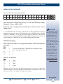
1
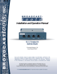
INC
®
Installation and Operation Manual
SRC-8 III
Serial Remote Control
Firmware version: 1.16
Manual Revised 07/31/07
Due to the dynamic nature of product design, the information contained in this
document is subject to change without notice. Broadcast Tools, Inc., assumes no
responsibility for errors and/or omissions contained in this document. Revisions
of this information or new editions may be issued to incorporate such changes.
Broadcast Tools® is a registered trademark of Broadcast Tools, Inc.
Copyright, 1989 - 2005 by Broadcast Tools, Inc. All rights reserved.
No part of this document may be reproduced or distributed without permission.
Visit www.broadcasttools.com for important product update information.
SRC-8 III Installation and Operation Manual
Table of Contents
Section Title
Page #
Introduction . . . . . . . . . . . . . . . . . . . . . . . . . . . . . . . . . . . . . . . . . . . . . 3
Safety Information . . . . . . . . . . . . . . . . . . . . . . . . . . . . . . . . . . . . . . . . 3
Who to Contact for Help . . . . . . . . . . . . . . . . . . . . . . . . . . . . . . . . . . . 3
Product Description . . . . . . . . . . . . . . . . . . . . . . . . . . . . . . . . . . . . . . . 4
Front Panel Description . . . . . . . . . . . . . . . . . . . . . . . . . . . . . . . . . . . . 4
Installation Guidelines . . . . . . . . . . . . . . . . . . . . . . . . . . . . . . . . . . . . . 5
Specifications . . . . . . . . . . . . . . . . . . . . . . . . . . . . . . . . . . . . . . . . . . . 10
Warranty . . . . . . . . . . . . . . . . . . . . . . . . . . . . . . . . . . . . . . . . . . . . . . . 11
CONTENTS
e-mail: [email protected] v o i c e : 360.854.9559 fax: 866.783.1742
2
SRC-8 III Installation and Operation Manual
INTRODUCTION
Thank you for your purchase of a Broadcast Tools® SRC-8 III, Serial Remote
Control (referred to as the SRC-8 III throughout this manual). We’re confident
that this product will give you many years of dependable service. This manual
is intended to give you all the information needed to install and operate the
Broadcast Tools® SRC-8 III.
SAFETY INFORMATION
CAUTION!
Broadcast Tools®
Products, as with any
electronic device, can
fail without warning.
Do not use this product
in applications where a
life threatening condition
could result due to failure.
Only qualified personnel should install Broadcast Tools® products. Incorrect or
inappropriate use and/or installation could result in a hazardous condition.
WHO TO CONTACT FOR HELP
If you have any questions regarding your product or you need assistance, please contact your distributor from whom you purchased this equipment.
NOTE:
This manual should be
read thoroughly before
installation and operation.
If you would like more information about Broadcast Tools® products, you may
reach us at:
Broadcast Tools, Inc.
131 State Street
Sedro-Woolley, WA 98284 USA
Voice: 360 . 854 . 9559
Fax: 866.783.1742
WEBSITE:
Internet Home Page: www.broadcasttools.com
E-mail:
[email protected]
THANK YOU FOR CHOOSING
BROADCAST TOOLS® BRAND PRODUCTS!
Visit our web site for
product updates and
additional information
INTRODUCTION
e-mail: [email protected] v o i c e : 360.854.9559 fax: 866.783.1742
3
SRC-8 III Installation and Operation Manual
PRODUCT DESCRIPTION
The Broadcast Tools® SRC-8 III is a computer interface to the real world. With
connection through an RS-232, RS-422 or RS-485 serial port, the SRC-8 III can
notify your PC software program that any of 8 optically isolated inputs has been
opened or closed and allows your software to control eight SPDT, 1-amp relays.
Communication with the SRC-8 III can be accomplished via short “burst” type
ASCII or binary commands from your PC (computer mode). Also, two units can be
operated in a standalone mode (master/slave mode) to form a "Relay extension
cord," with 8-channels of control in each direction. The unit can communicate using
RS-232, RS-422 or RS-485 at data rates up to 38400. The SRC-8 III may be
expanded to 32 inputs x 32 outputs. Optional external Ethernet and USB capabilities may be added.
The SRC-8 III is supplied with LED indicators to display input and relay status.
Three front panel LED’s display power, serial transmit and receive data. Removable
screw terminals are provided for ease of wire installation/removal.
Set-up:
Connect the supplied 9Vac power supply. The default baud rate setting is 9600, 8,
N, 1. The baud rate can be set to 2400, 4800, 9600 or 38400. This can be done using
either the ASCII or binary command formats listed below. Inputs can be simple contact closures or completely optically isolated with your external trigger sourcing current to the opto-isolators. The RS-232 serial connection is made to the male DB-9
connector. JP07 is used to reverse the RS-232 transmit and receive pins on the DB9. Factory setting is the “NN” position (Pin 5 = Ground, Pin 2 = Transmit and Pin
3 = Receive). RS-422/485 operation is via the removable screw terminals on the
rear of the unit.
FRONT PANEL DESCRIPTION
The front panel is equipped with eight red LED’s for each relay and eight green
LED’s for each input. The green “Power” LED will light when the SRC-8 III has
power connected.
DESCRIPTION
e-mail: [email protected] v o i c e : 360.854.9559 fax: 866.783.1742
4
SRC-8 III Installation and Operation Manual
INSTALLATION GUIDELINES
Rear panel dual-row 18-position connector
In
1A
K1
N.O.
In
1B
KI
Com
In
2A
K2
N.O.
In
2B
K2
Com
In
3A
K3
N.O.
In
3B
K3
Com
In
4A
K4
N.O.
In
4B
K4
Com
In
5A
K5
N.O.
In
5B
K5
Com
In
6A
K6
N.O.
In
6B
K6
Com
In
7A
K7
N.O.
In
7B
K7
Com
In
8A
K8
N.O.
In
8B
K8
Com
TX –
RS-422
RX –
RS-422
TX +
RS-422
RX +
RS-422
Each input may be configured for wet, dry or 5 volt TTL/CMOS logic compatible inputs. Factory default = DRY
Each relay may be configured for normally open or closed contacts. Factory
default = N.O.
It is recommended that all cables connected to the SRC-8 III should be looped
through ferrite cores to suppress RF. Surge protection with RF filtering such as the
Tripp Lite “ISOBAR 4” is also suggested for the power transformer. The purchase
of an inexpensive uninterruptible power supply (UPS) will provide back up in case
of power outages. Check out our web site for lightning protection links.
DIP Switch Settings:
DIP 1,2 The board address is set using switch numbers 1 and 2 in normal binary format:
12
00
=
0 (master) Set the SRC-8 III that will be connected to your
PC or data link to address 00.
01
=
1
10
=
2
11
=
3
DIP 3,4
34
00
01
10
11
Set baud rate
=
=
=
=
9600
2400
4800
38400
CAUTION!
Installation of the
SRC-8 III in high RF
environments should be
performed with care.
Shielded cable is suggested for all control,
audio inputs and outputs. All shields should
be tied to the “CHASSIS GROUND” terminal. The station
ground should be connected to the chassis
ground screw (CH1)
located behind J1 as
viewed from the rear.
For lightning protection devices, check out
www.polyphaser.com
and www.itwlinx.com.
The Baud rate will be set by the dipswitch on power up or reset. It can also be
changed using the serial port commands at other times, but if the SRC-8 III is reset
baud rate will be set according to the dipswitch settings.
INSTALLATION
e-mail: [email protected] v o i c e : 360.854.9559 fax: 866.783.1742
5
SRC-8 III Installation and Operation Manual
DIP 5 = (ON) Hex mode – When on, hex “Burst” mode is selected. Refer to the
protocol below for hex commands. (OFF) is ASCII mode. Refer to the ASCII protocol below for ASCII commands.
DIP 6 = (ON) Pair mode, inputs from one SRC-8 III will map directly to outputs of
another SRC-8 III when connected together via RS-232 or RS-422. (OFF) normal
operation via RS-232/422. DIP 5 must also be ON as pair mode only works in hex
mode.
NOTE: When in pair mode, as soon as a communication failure is detected, all
relays will be turned off. As soon as communications is restored, the relays will
be set according to the other unit’s inputs.
DIP 7 = (ON) will cause inputs to generate *uix<cr/lf>, on firmware version 1.16
or higher. Where * is the start character, u is Unit ID 0 – 7, i = Input number 1 – 8,
x = On/Off state, 1 = On, 0 = Off.
DIP 8 = Future feature creep
Pair Mode:
The SRC-8 can be used to transmit the outputs from one unit to another over a serial connection. The logical sense of the inputs is inverted when written to the outputs of its corresponding unit. Normally inputs are high and when closed go to a
logic 0 when in pair mode. When logic 0 is received, it will write logic 1 to the output. This allows the relay outputs 1-8 to come on if its corresponding input is closed.
Multiple units can also be set up to communicate with the same number of units on
the other end of a data link. All units must have DIP switches 5 and 6 turned on and
the unit addresses must have a corresponding unit on the other end of the link set to
the same address. For example, if you have two units on each side set to address 0
and 2, then the two units on the other side of the data link must also be set to 0 and
2. All units will automatically transmit the states of their inputs on power up, every
ten seconds and when any input changes state. If a unit does not receive an update
from its corresponding paired unit for a period of about 20 seconds, it will begin
flashing the red RX LED one second on, one second off. When communication is
restored, the LED will cease to flash.
WEBSITE:
Visit our web site for
product updates and
additional information
Pair mode can also be used to broadcast input closures from one unit to many using
a shared data link. The inputs on the transmit SRC-8 will appear on all of the receive
units as long as their address codes match. If only one unit is used at each site, it
must be set to an address of zero. The red RX LED will blink on the transmit side
to indicate it is not getting return data from the remote units, however the data being
broadcast will still cause the remote relays to follow their corresponding inputs on
the broadcasting unit.
INSTALLATION
e-mail: [email protected] v o i c e : 360.854.9559 fax: 866.783.1742
6
SRC-8 III Installation and Operation Manual
Connecting Multiple SRC-8’s:
Multiple SRC-8 III’s can be “daisy chained” together using a single serial port.
Units are daisy-chained using the 10 pin IDC “EXT” headers marked “EXT-J12”
and “EXT-J14”. Connect one end of the supplied ribbon cable to the “EXT-12”
header on the first SRC-8 III and the other end of the ribbon cable to the “EXT-14”
header of the next unit and so on. Each board should have a unique address set on
its dipswitch address setting. Up to three additional, SRC-8 III’s may be connected
together so that up to 32 inputs can be monitored and 32 relays controlled from one
PC’s com port, other serial devices or the external Ethernet/USB option. NOTE: In
order to use “external” units, JP10 must be kept in the 232/422-485/ position.
Serial Burst Mode Commands
The burst mode allows a computer or ASCII terminal to control and interrogate the
unit. This section defines all burst mode commands. Each burst mode command
starts with an asterisk (*). Next is a single decimal digit that corresponds to the unit
(ID) address 0-3. Following are one or more ASCII characters specifying the command. A carriage-return is required to terminate each command. If the command
requested a response, the response will consist of an upper case S, followed by the
unit address, and then the specific response. If acknowledgments are enabled, successful commands are responded to with RRR while errors get an EEE response.
The syntax of each command is given below. The syntax shows the command exactly as it should be sent, except that lower case characters represent values that should
be substituted:
Glossary of Command Notation
Character String
u
i
o
Meaning
Unit ID
Input Number
Relay/Output Number
Allowable Values
0-3
1-8
1-8
Set-up Commands
*uCEx - Enable Error and Good Responses - Where x = Y to enable and N = disable. In this mode, when a command is sent that is in error, the unit will reply (possibly before receiving the entire command) with “EEE.” If the command is sent correctly, the unit will reply with “RRR.”
Output Control Commands
*uORrL
- Latch Output r, output number
*uORrF
- Unlatch Output r, output number
*uORrPtt
- Pulse Output r, output number. Pulse Length tt: 00-99 corresponds
to 00 - 9.9 Seconds / r. Output number 1 --> 8
*uORrP
- Pulse Output r, output number 1 --> 8. Fixed Pulse Length = 700ms
INSTALLATION
e-mail: [email protected] v o i c e : 360.854.9559 fax: 866.783.1742
7
SRC-8 III Installation and Operation Manual
Information Retrieval Commands
*POLL - Respond with unit (ID) address in appropriate time slot. If there are multiple units on the line, each will respond with a different delay after receipt of this
command.
*uSPii - Send status of input ii. Response is SuP,ii,x where x is 0 if the corresponding input is high, 1 otherwise.
*uSPA - Send status of all inputs. Response is SuP,A,x,x,x,x,x,x,x,x<CR><LF>
where input 1 is first and input 8 is last. x is 0 if the corresponding input is high, 1
otherwise.
*uSR - Send status of all OUTPUTS. Response is: SuA,x,x,x,x,x,x,x,x<CR><LF>
*uU
- Send Unit Information :<name(SRC-8)><version n.nn><CR><LF>
Binary Commands
All commands start with a 2Ah (ASCII *). The first byte contains the board ID and
the byte count iiibbbbb. Byte count is number of bytes after the byte containing the
byte count including checksum. The second byte contains an 8-bit command. Some
commands are followed by data bytes. Checksum is the LSByte of the sum of all
bytes preceding checksum including start. Binary commands must be received as a
packet. If 50 ms or more passes after a character is received, with no new character
following, the SRC-8 III will begin looking for a new string if no valid data packet
has been received.
Commands to SRC-8 III
Command
40h
41h
42h
43h
44h
45h
46h
Additional Data Bytes
Function
RS-232 timer off
RS-232 timer on
Set serial speed to 2400
Set serial speed to 9600
Set serial speed to 4800
Set serial speed to 38400
Enable error & good responses
WEBSITE:
Visit our web site for
product updates and
additional information
INSTALLATION
e-mail: [email protected] v o i c e : 360.854.9559 fax: 866.783.1742
8
SRC-8 III Installation and Operation Manual
Command
47h
48h
49h
4Ah
Additional Data Bytes
4Bh
4Ch
4Dh
4Eh
4Fh
n
n
n
n
nt
Output Response from SRC-8 III
50h
51h
52h
n
53h
n
54h
nn
55h
n
Function
Disable error & good responses
Latch output n (00 – 07)
Unlatch output n (00 – 07)
Pulse output n (00 – 07), t= time
(1-63h =.1-9.9sec)
Poll output n (00 – 07) (see 55h)
Poll input n (00 – 07) (see 55h)
All Output status request (see 52h)
All Input status request (see 53h)
Unit version request (see 54h)
Function
Error response if enabled by 46h
Good response if enabled by 46h
Response of 4Dh, outputs are sent as 1 byte
Response of 4Eh, inputs are sent as 1 byte
Also sent when any input changes state
Response to 4Fh outputs version,
(i.e. 01h, 03h=ver 1.03)
Response to 4Bh or 4Ch for polled output or
input where the three highest bits of n are
used to identify if an input/output is low/high
and the lowest 5 bits
identify the input or output. n = 00h – 07h if
input n is low, n = 20h – 27h if input n is
high, n = 40h – 47h if output n is low and n =
60 – 67 if output n is high. n=cccnnnnn
where ccc = 000 = input low, 001 = input hi,
010 = output lo, 011 = output hi. nnnnn lowest 5 bits used to identify the input or output
Example of binary exchange:
To poll the status of outputs of unit 2 when outputs (0-7) 0, 6 are high, all else low:
Command string to SRC-8 III:
00101010b
2Ah
01000010b
42h
01001101b
10111001b
4Dh
B9h
Response string from SRC-8 III:
00101010b
2Ah
01000100b
44h
01010010b
52h
00000000b
01000001b
00000001b
00h
41h
01h
Start byte
Board ID 2 (010b), Byte count 2
(00010b)
All Output Status Request
Check sum (2Ah+42h+4Dh=B9h)
Start byte
Board ID 2 (010b), Byte count 4 (00100b)
Response code for an All Output Status
Request
Outputs 7-F are all low
Outputs 6 and 0 are high
Check sum (2Ah+44h+52h+00h+41h=01h)
INSTALLATION
e-mail: [email protected] v o i c e : 360.854.9559 fax: 866.783.1742
9
SRC-8 III Installation and Operation Manual
SPECIFICATIONS
Digital Inputs:
8 – Selectable 5 to 24 vdc optically Isolated or 5-volt
TTL/CMOS logic compatible input (Jumper selectable.
Factory default = Dry). 50 ms minimum duration.
Relay Outputs:
8 – SPDT, 1 amp/30 vdc relays. Jumper selectable either
N.O. or N.C.
Factory default = N.O.
RS-232 Serial Port:
2400, 4800, 9600, 38400 baud, 8 data bits, no parity, 1 stop bit.
Other baud rates may be requested.
RS-422 Serial Port:
2400, 4800,9600, 38400 baud, 8 data bits, no parity, 1 stop bit.
Other baud rates may be requested.
Ethernet Option:
Optional External Ethernet Device Server.
USB Option:
Optional external USB to Serial adapter.
Broadcast Tools® USB-RS-232
Display:
LED’s for inputs, relays, TX & RX serial data and power.
Interfacing:
Inputs - Removable (Euro)Screw terminals.
Relays - Removable (Euro)Screw terminals.
RS-232 Serial Port -Female DB-9. Data flow programmable.
RS-422 Serial port - Removable (Euro)Screw terminals.
Expansion port - Two, 10 position (2 x 5) .1” headers.
Logic:
Flash microprocessor / Non-volatile memory
Power:
9 Vac @500 ma / 120 Vac 50-60 Hz, “Wall Wart” Supplied.
(CE, 240 Vac 50-60 Hz optional)
Mechanical:
5.65” x 6.50” x 1.55” (WDH)
Weight:
2 pounds
Option:
RA-1 rack shelf for mounting up to three units in 1-RU.
Filler panels included.
SPECIFICATIONS
e-mail: [email protected] v o i c e : 360.854.9559 fax: 866.783.1742
10
SRC-8 III Installation and Operation Manual
LIMITED WARRANTY
The term “Buyer” as used in this document refers to and includes both (but only) (a) any person or entity who acquires such an item for
the purpose of resale to others (i.e., a dealer or distributor of an item), and (b) the first person or entity who acquires such an item for
such person’s or entity’s own use.
Broadcast Tools warrants to each Buyer of any item manufactured by Broadcast Tools that the item will be free from defects in materials and workmanship at the time it is shipped by Broadcast Tools if the item is properly installed, used and maintained.
EXCLUSIVE REMEDIES
If Broadcast Tools is notified, in writing, of a failure of any item manufactured by Broadcast Tools to conform to the foregoing Limited
Warranty within one (1) year following the date of the Buyer’s acquisition of the item, and if the item is returned to Broadcast Tools in
accordance with Broadcast Tools’ instructions for confirmation by inspection of the defect (which at Broadcast Tools’ election may
include, without limitation, a requirement that the Buyer first obtain a Return Authorization number from Broadcast Tools, that the Buyer
furnish proof of purchase in the form of an invoice and/or receipt, and that the Buyer prepay all freight charges associated with any return
of the item to Broadcast Tools using such freight service as Broadcast Tools reasonably may specify), Broadcast Tools will repair or
replace the defective item, or will refund the purchase price paid by the Buyer for the item. Broadcast Tools shall have the exclusive
right to choose between these alternative remedies.
NO OTHER WARRANTIES OR REMEDIES
TO THE MAXIMUM EXTENT PERMITTED BY APPLICABLE LAW, BROADCAST TOOLS AND ITS SUPPLIERS DISCLAIM ALL OTHER
WARRANTIES, EITHER EXPRESS OR IMPLIED, INCLUDING BUT NOT LIMITED TO IMPLIED WARRANTIES OF MERCHANTABILITY OR FITNESS FOR A PARTICULAR PURPOSE; AND THE FOREGOING ALTERNATIVE REMEDIES SHALL BE EXCLUSIVE OF
ALL OTHER REMEDIES. THIS LIMITED WARRANTY GIVES YOU SPECIFIC LEGAL RIGHTS. YOU MAY HAVE OTHER RIGHTS,
WHICH VARY FROM STATE/JURISDICTION TO STATE/JURISDICTION.
N O L I A B I L I T Y FOR CONSEQUENTIAL D A M A G E S
TO THE MAXIMUM EXTENT PERMITTED BY APPLICABLE LAW, NEITHER BROADCAST TOOLS NOR ANY OF ITS SUPPLIERS
SHALL HAVE ANY LIABILITY FOR ANY SPECIAL, INCIDENTAL, INDIRECT, CONSEQUENTIAL OR PUNITIVE DAMAGES WHATSOEVER (INCLUDING, WITHOUT LIMITATION, ANY DAMAGES FOR LOST PROFITS, BUSINESS INTERRUPTION, LOSS OF DATA OR
INFORMATION, COST OF CAPITAL, CLAIMS OF CUSTOMERS, OR ANY OTHER PECUNIARY LOSS) ARISING OUT OF THE USE
OF OR THE INABILITY TO USE ANY ITEM SUPPLIED BY BROADCAST TOOLS, EVEN IF BROADCAST TOOLS HAS BEEN
ADVISED OF THE POSSIBILITY OF SUCH DAMAGES HAVE ANY LIABILITY FOR ANY SPECIAL, INCIDENTAL, CONSEQUENTIAL,
EXEMPLARY OR PUNITIVE DAMAGES. THIS LIMITATION OF LIABILITY APPLIES WHETHER A CLAIM IS ONE ALLEGING
BREACH OF A CONTRACT OR WARRANTY, NEGLIGENCE OR OTHER TORT, FOR THE VIOLATION OF ANY STATUTORY DUTY,
THE FAILURE OF ANY LIMITED OR EXCLUSIVE REMEDY TO ACHIEVE ITS ESSENTIAL PURPOSE, OR ANY OTHER CLAIM OF
ANY NATURE. BECAUSE SOME STATES AND JURISDICTIONS DO NOT ALLOW THE EXCLUSION OR LIMITATION OF LIABILITY
FOR INCIDENTAL OR CONSEQUENTIAL DAMAGES, THIS LIMITATION MAY NOT APPLY TO YOU.
Broadcast Tools, Inc.
131 State Street
Sedro-Woolley, WA 98284 • USA
360.854.9559 voice • 866.783.1742fax
[email protected] e-mail
www.broadcasttools.com website
LIMITED WARRANTY
e-mail: [email protected] v o i c e : 360.854.9559 fax: 866.783.1742
11