1
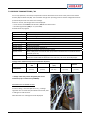
HOBART CHINA SERVICE MANUAL EFFICIENT – RELIABLE – INNOVATIVE SERVICE MANUAL AMX/AM900 SERIES Starting from Serial No 210910000 This document is produced for internal use only. The detailed settings and servicing must be carried out by service technicians qualified by HOBART. Reproduction of this document is prohibited without the written permission of HOBART. Version 1.0 0911 . R&D, HOBART CHINA
AMX/AM900 / 1 AMX/AM900 SERVICE MANUAL
As continued product improvement is a policy of HOBART, specifications are subject to change without notice. 2 / AMX/AM900
. R&D, HOBART CHINA CONTENT 1. STANDARD MODELS – OVERVIEW ........................................................................................................................ 4 2. MACHINE DIMENSIONS ........................................................................................................................................ 5 3. INSTALLATION ....................................................................................................................................................... 6 3.1 ELECTRICAL CONNECTION ............................................................................................................................. 6 3.2 WATER CONNECTION ..................................................................................................................................... 6 3.3 DRAIN CONNECTION ...................................................................................................................................... 6 4. SMARTRONIC CONTROLS ...................................................................................................................................... 7 4.1 AM900 SERIES ................................................................................................................................................ 7 4.2 AMX SERIES .................................................................................................................................................... 8 5. FIRST RUN / CUSTOMER MENU ............................................................................................................................ 9 6. HYDRAULIC SCHEMATICS .................................................................................................................................... 10 6.1 LEGEND OF COMPONENTS .......................................................................................................................... 10 6.2 AM900 ......................................................................................................................................................... 11 6.3 AMX ............................................................................................................................................................. 12 7. FILLING ................................................................................................................................................................ 14 7.1 AIRGAP ......................................................................................................................................................... 14 7.2 PRESSURE TRANSMITTER B3 / B4 ................................................................................................................ 15 7.3 DOSING EQUIPMENT ................................................................................................................................... 16 7.3.1 DETERGENT / RINSE AID DISPENSER ......................................................................................................... 16 7.3.2 ADJUSTMENT OF CHEMICALS DEFICIENCY SENSORS ............................................................................... 17 7.4 SOFTENER .................................................................................................................................................... 18 7.4.1 GENERAL ................................................................................................................................................... 18 7.4.2 SOFTENER CHECK PROCEDURE ................................................................................................................. 19 7.4.3 SOFTENER TEST PROGRAM ....................................................................................................................... 20 7.5 BOOSTER / TANK / TEMPERATURE PROBES ................................................................................................. 21 8. WASHING ............................................................................................................................................................... 22 8.1 WASH PUMP AND STRAINER SYSTEM .......................................................................................................... 22 8.1.1 FUNCTION (AMX only) .............................................................................................................................. 22 8.1.2 TECHNICAL DATA ....................................................................................................................................... 23 8.2 RINSE PUMP ................................................................................................................................................. 23 9. HOOD – DETAILS .................................................................................................................................................... 24 10. HEAT RECOVERY ................................................................................................................................................... 25 11. ELECTRONIC CONTROL ......................................................................................................................................... 26 11.1 KEY COMBINATIONS ................................................................................................................................... 26 11.1.1 BASIC OPERATION / CUSTOMER SETTINGS ............................................................................................. 26 11.1.2 SERVICE MENU........................................................................................................................................ 27 11.1.3 PROGRAMMING / MODIFICATION OF BASIC DATA / SOFTENER TEST .................................................... 28 11.2 PRINTED CIRCUIT BOARDS ......................................................................................................................... 29 11.2.1 MAIN BOARD .......................................................................................................................................... 29 11.2.2 EXTENSION BOARD A3 ............................................................................................................................ 30 11.3 COUNTER FUNCTIONS ............................................................................................................................... 31 12. FAULTS .................................................................................................................................................................. 32 12.1 UNCRITICAL FAULTS ................................................................................................................................... 32 12.2 CRITICAL FAULTS ........................................................................................................................................ 33 12.3 OTHER INDICATIONS .................................................................................................................................. 34 . R&D, HOBART CHINA
AMX/AM900 / 3 AMX/AM900 SERVICE MANUAL
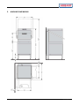
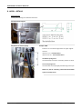
1. STANDARD MODELS – OVERVIEW
AMX
AM900
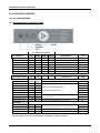
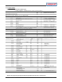
TYP NO. DEVICE NUMBER PROGRAM NO AM900‐xxxx‐312 897547‐010 005 AM900‐xxxx‐306/302 897547‐010 005 AM900‐xxxx‐300 897547‐010 009 AM900‐xxxx‐312D 897547‐010 006 AM900‐xxxx‐306/302D 897547‐010 006 AM900‐xxxx‐300D 897547‐010 010 AM900‐xxxx‐312T 897547‐010 015 AM900‐xxxx‐306/302T 897547‐010 015 AM900‐xxxx‐300T 897547‐010 019 AM900‐xxxx‐312DT 897547‐010 016 AM900‐xxxx‐306/302DT 897547‐010 016 AM900‐xxxx‐300DT 897547‐010 020 AMX‐xxxx‐312(H) 897547‐010 001 AMX‐xxxx‐306/302(H) 897547‐010 001 AMX‐xxxx‐300(H) 897547‐010 007 AMX‐xxxx‐312(H)D 897547‐010 003 AMX‐xxxx‐306/302(H)D 897547‐010 003 AMX‐xxxx‐300(H)D 897547‐010 008 AMX‐xxxx‐312 (H)S 897547‐010 002 AMX‐xxxx‐306/302(H)S 897547‐010 002 AMX‐xxxx‐312 (H)DS 897547‐010 004 AMX‐xxxx‐306/302(H)DS 897547‐010 004 AMX‐xxxx‐312(H)T 897547‐010 011 AMX‐xxxx‐306/302(H)T 897547‐010 011 AMX‐xxxx‐300(H)T 897547‐010 017 AMX‐xxxx‐312/306(H)DT 897547‐010 013 AMX‐xxxx‐312/306(H)DT 897547‐010 013 AMX‐xxxx‐300(H)DT 897547‐010 018 AMX‐xxxx‐312(H)ST 897547‐010 012 AMX‐xxxx‐306/302(H)ST 897547‐010 012 AMX‐xxxx‐312(H)DST 897547‐010 014 AMX‐xxxx‐306/302(H)DST 897547‐010 014 Device Code Explanation AM900 = Manual drain AMX = With Genius‐X2, auto drain 4 / AMX/AM900
EPROM COMMENT D = With detergent dispenser H = Hood insulation S = With Softener T = With tubular rinse arm . R&D, HOBART CHINA 2. MACHINE DIMENSIONS . R&D, HOBART CHINA
AMX/AM900 / 5 AMX/AM900 SERVICE MANUAL
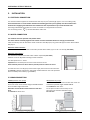
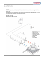
3. INSTALLATION 3.1 ELECTRICAL CONNECTION The machines will be supplied as standard with cable 6 (or 4) mm2 (cable length approx. 2 m from cable gland). A fused disconnects or circuit breaker with electrical leaking protector (not supplied) must be installed in the electrical line supplying the dishwasher and should meet the requirements of your local electrical code. According to EN 60 335 the appliance must be connected to an equipotential conductor. The connecting screw ( ) is located beside the cable inlet. 3.2 WATER CONNECTION The machines must be operated with potable water. For water with an extremely high mineral content an external demineralization is strongly recommended. Ideal conductivity value for washware made of stainless steel 80 μS/cm, for glasses 100 μS/cm and for dishes 200 to 400 μS/cm Machines without softener: The machine should be connected to soft and if possible warm water (up to 3 °dh = 0.5 mmol/l, max. 60°C). Machines with softener: The machine should be connected to warm water if possible (max. 60°C). Softener has to be adjusted according to water hardness. Line flow pressure 0.5 – 10 bar. Important: the line flow pressure must not be less than 0.5 bar. If the line flow pressure is above 10 bars provide pressure reducer at source. Connect the union nut "A" (3/4") of the water supply hose to the site shut off valve. Do not kink or cut the supply hose. Eventually needed extension has to be provided with a suitable pressure hose (e.g. 324088‐1). 3.3 DRAIN CONNECTION AM900 (without drain pump) Ensure gravity drain. Drain hose must not exceed the height of 0.1 m between floor and lower edge of the hose. Otherwise it could be that water remains in tank and hose. Do not kink the drain hose. 6 / AMX/AM900
AMX (with drain pump) Connection between machine and site drain must not exceed the specified height of max. 0.75 m. Do not kink the drain hose. Do not place the drain hose loosely on the floor (the hose could be rubbed through). Fix it at site!
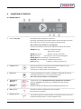
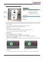
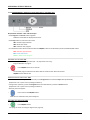
. R&D, HOBART CHINA 4. SMARTRONIC CONTROLS 4.1 AM900 SERIES 1
Machine ON / OFF Pushing this button switches the machine on. By pushing and holding (3 seconds) this button, the self cleaning cycle starts. At the end of the cycle, the machine switches off automatically. After switch off, the machine is not voltage free! Furthermore the button illuminates to indicate the mode of the machine: GREEN (flashing) GREEN (permanent) = Machine is ready for operation. RED (permanent) = Critical failure (machine type setting U01) GREEN /RED (alternate flashing) = noncritical failure BLUE/RED (alternate flashing) = negative pressure failure BLUE (flashing) = Machine is draining / switches off.
= Machine is filling and heating. Wash cycle is running. 2
Program button By pushing this button it is possible to select between different preset programs, according to model and equipment. The program no. will be shown in the upper Display.
3
Stop button In case of operating error or faults, it is possible to switch‐off the machine immediately without drain cycle, by pushing this button. After switch off, the machine is not voltage free! 4
5
Temperature Wash (°C) Temperature Rinse (°C) Temperatures are only displayed when the program button is pushed for minimum 3 seconds. The indicators go out 10 seconds after releasing program button. Permanent temperature display can be activated (set U02 S15 to "1”). 6
Salt required Indicates the need for regeneration salt to be added. (Only with built‐in softener.) Service indicator This symbol indicates that the dishwasher has developed a fault. In the rinse 7
temperature display appears a code (see page 33 to 35). . R&D, HOBART CHINA
AMX/AM900 / 7 AMX/AM900 SERVICE MANUAL
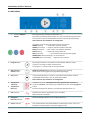
4.2 AMX SERIES 1
Machine ON/OFF DRAIN Pushing this button switches the dishwasher on. By pushing and holding (3s) this button, the drain and self cleaning cycle starts. Once the drain cycle has completed the machine switches off automatically. After switch off, the machine is not voltage free! The button illuminates to indicate the mode of the machine: GREEN (flashing) = machine fills and starts heating GREEN (permanent) = ready for operation (softener test U03) BLUE (permanent) = wash cycle is running (basic data U02) BLUE (flashing) = machine draining / switch‐off RED (permanent) = critical failure (machine type setting U01) GREEN /RED (alternate flashing) = noncritical failure BLUE/RED (alternate flashing) = negative pressure failure
2
Program button By pushing this button it is possible to select between different preset programs, according to model and equipment. The program no. will be shown in the upper Display. 3
High pressure / Service button AUXX (L/T) models only: An activation of high pressure cleaning. Never use for cleaning glasses and light dishes (breakage)! 4
Stop button In case of operating error or faults, it is possible to switch‐off the machine immediately without drain cycle, by pushing this button. After switch off, the machine is not voltage free!
Temperature Wash (°C) Temperature Rinse (°C) Temperatures are only displayed when the program button is pushed for minimum 3 seconds. The indicators go out 10 seconds after releasing program button. Permanent temperature display can be activated (set U02 S15 to "1”). Salt required Indicates the need for regeneration salt to be added. (Only with built‐in softener.) Detergent / Rinse aid indicator Indicates detergent (CH1) or rinse aid (CH2) deficiency. 5
6
7
8
9
Service indicator This symbol indicates that the dishwasher has developed a fault. In the rinse temperature display appears a code (see page 33 to 35).
8 / AMX/AM900
. R&D, HOBART CHINA 5. FIRST RUN / CUSTOMER MENU Initial fill of the rinse booster On delivery, the switching function S28 (first booster filling) is set to "0". There is no menu "boF". As the booster is controlled by a pressure transmitter, no initial fill must be carried out. Therefore the booster heating is not locked. Requirement: Machine "OF" and hood open If the hood will be closed or if no button is pressed within 10 seconds, the display switches off automatically and the new settings will be saved. Push Stop and Program button at the same time. DISPLAY EXAMPLE: Select function with the program button. Rinse Wash CH1 XX Parameter Range C16 0‐50 s 1 Detergent dosage 2 Rinse aid dosage – program P01 to P04 CH2 XX C18 0‐50 s 3 Detergent dosage – not used CH3 ‐ ‐ C20 0‐50 s 4 Rinse aid dosage – program basic clean (AUP only) CH4 XX C19 0‐50 s Set chemicals values with the ON/OFF button (0.5s steps). 5 Water hardness adjustment Set value with the ON/OFF button (basic setting H02). H01 = up to 7°dh / H02 = 8 to 14°dh / H03 = 15 to 21°dh / H04 = 22 to 30°dh To initiate a manually regeneration with the next wash cycle press the stop button for 3 seconds (confirmed by the flashing water hardness indication). 6 7 8 Wash cycle counter Reset to "0" only via basic data (service menu). Water consumption counter Reset to "0" only via basic data (service menu). Remaining water quantity counter for external water treatment H01 Up to H04 C60 ‐ C63 Hereby the softener function will be set to initial condition. (With next wash cycle, regeneration starts automatically.) PXX XXX C73 + C74 0‐999999 EXX XXX C77 + C78 0‐999999 dXX XXX C79 + C80 0‐999999 S18 SF1 ‐ ‐ 0 ‐ ‐ 1 0 / 1 SF2 ‐ ‐ 0 ‐ ‐ 1 0 / 1 Acoustic signal (AUP models only) S S24 0 / 1 By pushing the ON/OFF button acoustic signals will be activated ("1") or deactivated ("0"). There are 3 different signals: end of program: 1 x 2.0s "ON" noncritical failure: 2 x 0.5s with 0.5s pause critical failure: 5s continuous signal S ‐ ‐ 0 / ‐ ‐ 1 To reset the counter to pre‐set value, press ON/OFF button for 3 seconds. CLOSE THE HOOD 9 10 Hose priming detergent (dispenser M4) By pushing the ON/OFF button, relay 5 will be activated for 60 seconds. Hose priming rinse aid (dispenser M3) By pushing the ON/OFF button, relay 6 will be activated for: AMX(X) / AUXX = 360 seconds / AUP = 130 seconds To interrupt a priming cycle, push the ON/OFF button again. 11 12 Chemicals deficiency sensor By pushing the ON/OFF button sensors will be activated ("1") or deactivated ("0"). CH ‐ ‐ 0 / ‐ ‐ 1 0 / 1 To quit the menu : – point 1 to 8 – close the hood, point 9 to 11 – open the hood – or do not press any button during next 10 seconds The indicator switches itself off and the new settings will be saved. . R&D, HOBART CHINA
AMX/AM900 / 9 AMX/AM900 SERVICE MANUAL
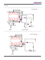
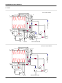
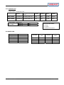
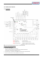
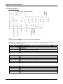
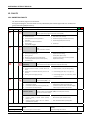
6. HYDRAULIC SCHEMATICS 6.1 LEGEND OF COMPONENTS B1 TEMPERATURE SENSOR BOOSTER B2 TEMPERATURE SENSOR TANK B3 PRESSURE TRANSMITTER BOOSTER B4 PRESSURE TRANSMITTER TANK E1 BOOSTER HEATING E2 TANK HEATING M1 WASH PUMP M2 RINSE PRESSURE PUMP M3 RINSE AID DISPENSER M4 DETERGENT DISPENSER M5 DRAIN PUMP S1 REED‐SWITCH – HOOD S2 AIRGAP IMPELLER 1) S3 SALT DEFICIENCY SWITCH 2) S4 REED‐SWITCH – STRAINER Y1 SOLENOID VALVE – FILL Y3.1 VALVE RESIN A 2) Y3.2 VALVE RESIN B 2) Y4.1 VALVE RESIN B/A 2) Y4.2 VALVE DRAIN/BOOSTER 2) 1 WATER SUPPLY HOSE 2 WATER INLET AIRGAP 1) 3 BOOSTER 4 WASH ARM 5 RINSE ARM 6 SALT CHAMBER 2) 7 RESIN A / RESIN B 2) 1)
AIRGAP ASSY. 2)
SOFTENER ASSY.B1 10 / AMX/AM900
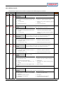
. R&D, HOBART CHINA 6.2 AM900 带升温箱
WITH BOOSTER
S1
2
S2
4
5
Y1
1
M4
B4
S4
1E2
B3
M3
M1
B1
3
1E1
(2E1)
排水
DRAIN
M2
BOOSTER DRAIN
WITHOUT
BOOSTER
不带升温箱
S1
4
5
1
M4
B4
1E2
S4
M1
M3
B1
M2
排水
DRAIN
. R&D, HOBART CHINA
AMX/AM900 / 11 AMX/AM900 SERVICE MANUAL
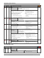
6.3 AMX WITH
SOFTENER
带软水器
S1
2
S2
4
5
Y1
1
M4
B4
1E2
S4
B3
Y4.2
M3
6
M1
7B
7A
3
B1
S3
1E1
(2E1)
M2
Y3.2
M5
Y4.1
排水
DRAIN
Y3.1
升温箱排水
BOOSTER
DRAIN
WITHOUT SOFTENER
不带软水器
S1
2
S2
4
5
Y1
1
M4
B4
1E2
S4
B3
M3
M1
B1
1E1
(2E1)
3
M2
M5
DRAIN
排水
12 / AMX/AM900
BOOSTER
DRAIN
升温箱排水
. R&D, HOBART CHINA WITHOUT SOFTENER
不带软水器、不带升温箱
WITHOUT BOOSTER
S1
4
5
1
M4
B4
1E2
S4
M1
M3
B1
M2
M5
排水
DRAIN
. R&D, HOBART CHINA
AMX/AM900 / 13 AMX/AM900 SERVICE MANUAL
7. FILLING 7.1 AIRGAP The reed‐switch S2 on the small PCB 775540‐1 is actuated by the impeller magnet. The impeller monitors the incoming water flow by counting impulses and then relaying that information back to the main PCB. The count rate is 200 impulses per liter. 1. Water consumption counter [C77] + [C78] (counted liters are added to basic value "0"). 2. Remaining water quantity counter for external water treatment [C79] + [C80] + [S18] (counted liters are subtracted from preset value). See also chap. 11.3, page 32. MAINTENANCE – TO BE CHECKED: Whether leaking water from the airgap overflow (see figure1)) enters the wash tank chamber (visual inspection). If so, the leaking water quantity must not exceed 100 ml per fill step. Whether the impeller sensor works. This can be carried out in two ways. 1. Service Menu: Select input S2 and activate the fill valve by pushing the ON/OFF button (‐‐0 / ‐‐1 will be displayed alternately). See also chap. 11.1.2, page 28. 2. Visual check: quick flashing LED on main board (see page 30). NOTE: To avoid incrustations, the fill valve is activated during stand‐by every 20 minutes for a short time to humidify the nozzles inside the airgap. (Parameter [S45] set to "1".) 14 / AMX/AM900
. R&D, HOBART CHINA 7.2 PRESSURE TRANSMITTER B3 / B4 Via air traps (booster / wash tank) compressed air will be directed via clear hoses to the pressure transmitter booster (B3) and wash tank (B4). The transmitter changes the upcoming pressure into DC voltage which will be processed by the control as water level message. If there is no fault, the voltage value can be displayed: – via the service menu F03 fill level booster / F04 fill level wash tank or – set switching function [S56] to "1" (menu U02). Possible faults see page 34 Pressure transmitter B3 (booster) Output voltage * Booster is empty. Fill valve will be activated. approx. 0.50 V Booster heating will be switched on (heating up to fill start temperature 85°C). approx. 0.62 V Booster is filled. Fill valve closes. approx. 0.90 V Pressure transmitter B4 (tank) – example AMX Output voltage * Wash tank is empty. approx. 0.50 V Tank heating will be switched on. approx. 0.65 V Machine is ready for operation (tank is filled). approx. 1.00 V approx. 1.15 V With a delay‐time of 5 seconds drain pump will be activated until normal water level is reached. (Error UL)
approx. 0.60 V At the end of the self cleaning cycle water remains in the wash tank. When the machine will be switched on the next time, "AL" error will be displayed.
Voltage value* additions for pressure transmitter B4 (tank): Negative Model tank filled AL tank heating safety level pressure ON (UL) AMX/AM900 0.65V (ca.13 l) 1.00V (ca.21 l) 1.30V (ca. 27 l) 0.60V (ca. 12 l) 0.58V (ca. 11 l) * Voltage values may not be changed by the service technician (only on instruction of HOBART). MACHINES WITH EXTERNAL FILLING If external filling is activated (S20 set to "1"), a voltage regulation of 0.1 V must take place within 30 seconds, after a holding time of 60 seconds. Otherwise the error message FIL will be displayed. . R&D, HOBART CHINA
AMX/AM900 / 15 AMX/AM900 SERVICE MANUAL
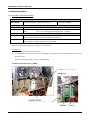
7.3 DOSING EQUIPMENT 7.3.1 DETERGENT / RINSE AID DISPENSER Dispensers Detergent (775556‐12): delivery rate 3.0 l/hr AMX/ AM900 Rinse aid (775556‐11): delivery rate 0.4 l/hr hose inside: 775608‐2 hose inside: 775608‐1 Pre‐adjusted values All models: "8" = 8.0 s ≈ 2.40 g/l (possible range 0‐50 s ≈ 0‐15.4 g/l) Detergent CH1 Rinse aid CH2 AMX/AM900: "7.0" = 7.0 s ≈ 0.31 g/l (possible range 0‐50 s ≈ 0‐2.2 g/l) AUP: "2.5" = 2.5 s ≈ 0.33 g/l (possible range 0‐50 s ≈ 0‐6.6 g/l) Dosage Pre‐dosing is activated simultaneous with rinse pump M2. Detergent Wash dosing is activated simultaneous with the wash pump. Rinse aid Pre‐dosing is activated after the end of the fill cycle. Wash dosing is activated after the end of wash cycle. Hose priming and factory settings see page 8 "Customer Menu". Maintenance 1.
Check hoses, dispensers and connections. 2.
As a precaution, the dosing hoses have to be replaced every two years (hoses inside dispensers, suction and pressure hoses). Dosing hoses (sold by meter) – part no. 01‐246301‐099 Installation of dosing hoses (e.g. AMXX): 16 / AMX/AM900
. R&D, HOBART CHINA 7.3.2 ADJUSTMENT OF CHEMICALS DEFICIENCY SENSORS POTENTIOMETER: Graduations: 1 to 9 Sensitivity: 1 (non‐sensitive chemical sensing / sensitive failure indication 9 (sensitive chemical sensing / non‐sensitive failure indication) Basic setting: 3 Detergent
Rinse aid
Due to the physical properties of rinse aid (e.g. wetting), even smallest rinse aid quantities inside the hose will be detected by the deficiency sensor. If the sensor is adjusted too sensitively, maybe deficiency will not be released. – TEST "DEFICIENCY" Flush the suction hose thoroughly with fresh water to remove any chemicals. When the hose is drained, the respective LED should be "OF". – TEST "FULL" Fill the suction hose (see chapter 5, page 8). The respective LED should light up. If not, adjust potentiometer until the LED lights up. Now the hose should be completely filled and without air bubbles. TESTING THE PCB – Select Service Mode (see chapter 111.1.2, page 28). – Hoses are empty and deficiency sensor potentiometers turned to left stop: Switching functions "S07" (detergent) and "S08" (rinse aid) must be "0". No sensor LED lights up. – Potentiometers turned to right stop: Switching functions "S07" (detergent) and "S08" (rinse aid) must be "1". The LED of the respective circuit lights up. Detergent deficiency indication "‐ ‐ 0" Rinse aid hose filled "‐ ‐ 1" – After testing: Set potentiometers (detergent and rinse aid) to value "3" (based on tests with the most common products).
. R&D, HOBART CHINA
AMX/AM900 / 17 AMX/AM900 SERVICE MANUAL
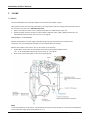
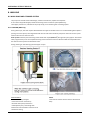
7.4 SOFTENER 7.4.1 GENERAL Before first run, the softener has to be filled with 2 kg of regeneration salt and potable water. Switching function: [S05] = "1" (standard setting for machine programs with softener) Salt capacity: max. 2 kg (coarse grained, max.10 mm – no tablets) Salt consumption: approx. 40 g / regeneration Softener setting: see next page Parameters: [C84] number of salt fillings (see also page 33) [C85] number of wash cycles with deficiency of salt NOTE: 1.
Manually initiation of regeneration (salting column "B") is possible. See also page 8, "customer menu" point 5. 2.
Y4.2 (switching Drain / Booster) de‐energized = switched to drain / energized = filling into booster. It will take several wash cycles until the salt indicator switches off. left hand view right hand view front view rear view 1) Special tool needed (softener wrench 01‐293500‐1) In case of softener replacement the fastening nut has to be re‐tighten after three wash cycles. 18 / AMX/AM900
. R&D, HOBART CHINA 7.4.2 SOFTENER CHECK PROCEDURE Check: Parameter [C84] = number of salt fillings. Parameter [C85] = number of wash cycles with deficiency of salt (illuminated salt indicator). What you need to verify the softener function: 1. Test kit to measure the water hardness (part number 607236). Pay attention to expiry‐date. 2. A conductivity‐meter (possibly pH indicator strips 609927). How respectively where to measure? Use clean tea‐cup or beaker for sampling water. 1. Take measurement of the total water hardness (°dh) at the tap where the machine is connected to. 2. Measure the conductivity (μS/cm) at the tap where the machine is connected to. 3. Measure the hardness of the water in the booster. Therefore, the booster drain hose is to be used. Discard the first cup of water to ensure that no residuals from the hose falsify the measured value. 4. Measure the conductivity of the booster water. Adjustment of softener setting according to the hardness of incoming water: 1. Ensure adequate softener setting: H01 = up to 7°dh / H02 = 8 to 14°dh / H03 = 15 to 21°dh / H04 = 22 to 30°dh. 2. Ensure that the salt chamber contains salt. 3. Ensure that granular salt is used (salt tablets are not allowed). 4. Ensure that the salt chamber has been filled up with water. Approximate values if softener function is O.K.: The conductivity of the booster water shall be about 300μS/cm higher than the conductivity of that water taken at the tap. For example: If the total hardness of the incoming water is 500μS/cm, the conductivity of the booster water will be roughly 800μS/cm. If this value is significantly higher (e.g. 3000 μS/cm), an incorrect softener function is very likely. Further steps: 1. Adjust the softener to "H04" to ensure a new regeneration will be actuated every 3 cycles. 2. Select the shortest program “P01” and take a sample of water (a tea‐cup) at the booster drain hose immediately after the program cycle has ceased. 3. Measure and note down the water hardness. 4. Measure and note down the conductivity. Repeat procedures 1 to 4 seven times to ensure salting of both resin columns. An incorrect softener function is most supposable if the measured hardness at the booster drain hose is higher than 5°dh and / or the conductivity is extremely high (i. e. in the range of 3000 μS/cm). Proceed as following in case of too high hardness and / or conductivity values: 1. Run the drain cycle to ensure booster emptying down to the pump intake. 2. Remove the side panels. 3. Activate the softener test program "U03" as described on next page. Observe the resin columns with the aid of a torch from the left hand side of the machine. (Column "A" is at the left, column "B" is at the right from this point of view). If the sequential operation deviates from the described one (see next page), i. e. resin "B" was six times activated, it is very likely that a softener valve is jamming or the electrical connections are interchanged (this is less probable). The booster must be flushed thoroughly at the end of this procedure (run 5 wash cycles) to ensure the chloride content is at an acceptable level to prevent corrosion. Never run the softener test program at the begin of the herein described procedure because it is unavoidable that salt will be flushed into the system. Thus, measurements would become incorrect. . R&D, HOBART CHINA
AMX/AM900 / 19 AMX/AM900 SERVICE MANUAL
7.4.3 SOFTENER TEST PROGRAM REQUIREMENT: Machine has to be switched "OFF" and the hood must be open. – Push and hold program and service button (dryer button) together. U01 appears in the rinse temperature display. – Select softener test program U03 by pushing the stop button. – To enter U03 push the ON/OFF button. The ON/OFF button illuminates GREEN while the test program is running. Once the test sequence has completed, the ON/OFF button will switch off. 20 / AMX/AM900
. R&D, HOBART CHINA 7.5 BOOSTER / TANK / TEMPERATURE PROBES BOOSTER Booster heating: 12.6/6.3/0 kW Total volume: 10.3 liter Useable volume: 5.2 liter Water consumption / rinse cycle: 2.5 liter Part numbers: Booster heating E1 02‐240135‐002/00 O‐ring – booster heating 01‐240135‐011 Air trap 01‐240076‐002 O‐ring – air trap 01‐276903‐050 TANK Tank heating: Tank volume (liter): 3 kW 21 L Part numbers: Tank heating E2 02‐883432‐001 Air trap 01‐240076‐002 O‐ring – air trap 01‐276903‐050 TEMPERATURE PROBES Part numbers: Temperature probe booster B1 00‐775612‐001 Temperature probe tank B2 00‐775612‐001 min. – 40°C Temperature range: max. + 125°C Possible faults see page 34. . R&D, HOBART CHINA
AMX/AM900 / 21 AMX/AM900 SERVICE MANUAL
8. WASHING 8.1 WASH PUMP AND STRAINER SYSTEM The pump unit includes motor with flange, mechanical shaft seal, impeller and capacitor. A non return flap (called Flipper) allows the draining of the circulation system (AMX only). The Flipper prevents soil, collected in the pump sump, from reentering the circulating system. 8.1.1 FUNCTION (AMX only)
During wash cycle, the wash liquid is distributed to the upper and lower wash arm. The back flowing wash liquid is passing a strainer system, the integrated intake strainer and enters the wash pump from the outer annular space of the suction unit via the main duct. Drain system: Used for partial draining of the soiled wash liquid (Genius X2) during wash cycle (approx. 20 seconds after program start) or for the complete draining of the wash tank. Pressure‐side the soiled wash liquid will enter the drain via hose system and ventilation valve. During draining or self‐cleaning cycle the flipper is open. MAINTENANCE – Check movability of flipper. – Clean fine strainer if necessary. – Remove drain pump and clean it. – Subsequently carry out leakage test. Furthermore the ventilation valve has to be checked for soiling. 22 / AMX/AM900
NOTE: Tank strainer and fine strainer have to be cleaned daily. . R&D, HOBART CHINA 8.1.2 TECHNICAL DATA WASH PUMPS – CONNECTED LOAD Voltage / Frequency / Part no. Phases Current Capacitor Power Impeller AMX / AM900 02‐883617‐1 220‐240V / 50Hz / 1P 3.2A 16μF 0.73kW 104mm AMX / AM900 02‐883617‐2 220‐240V / 60Hz / 1P 3.4A 16μF 0.73kW 94mm WASH PUMPS – SERVICE KITS 883617‐10 AMX / AMXT 883617‐20 The Service Kits include: 50Hz 60Hz 1. O‐ring 2. Impeller 3. Mechanical shaft seal 8.2 RINSE PUMP Part number Voltage Frequency Current Power Capacitor . R&D, HOBART CHINA
7618008 220‐240 V 50/60 Hz 0.46 A 0.09 kW 5.0 μF / 400V rinse time 7.5 s
8.0 s
8.5 s
9.0 s
Average value 2.5 l
2.8 l
2.9 l
3.1 l
rinse time 9.5 s 10.0 s 10.5 s 11.0 s Average value 3.2 l
3.4 l
3.5 l
3.6 l
AMX/AM900 / 23 AMX/AM900 SERVICE MANUAL
9. HOOD – DETAILS MAINTENANCE Check plastic bearings for sufficient lubrication. Hood lift handle Support Adjustment of tension springs Example: AMX Distance "A" from lower edge of bent to upper edge of channel: approx. 12 cm – insulated hood approx. 18.5 cm – non‐insulated hood Insufficient spring force: The hood keeps not safe in "stand‐by" position or closes. Too much spring force: The hood does not keep tightly closed during wash cycle. Make sure, that in "stand‐by" position the hood neither opens nor slowly closes. 24 / AMX/AM900
. R&D, HOBART CHINA 10. HEAT RECOVERY GENERAL With activation of the fill valve (booster refill), the control 897545‐1 will be actuated by an impulse and starts the drain pump (partial tank draining, approx. 2.5 l) simultaneous to filling. The output clock signal is adjustable via basic data. The fresh water enters via the airgap the outer coaxial pipe of the heat exchanger and will be heated up by tank water, flowing in the inner coaxial pipe (counter‐flow principle). Menu U02 – Basic Data: Switching function [S32] is set to "1". . R&D, HOBART CHINA
AMX/AM900 / 25 AMX/AM900 SERVICE MANUAL
11. ELECTRONIC CONTROL 11.1 KEY COMBINATIONS 11.1.1 BASIC OPERATION / CUSTOMER SETTINGS X = button to be pushed BASIC OPERATION STOP PROGR. SERVICE ON/OFF REQUIREMENTS HOOD Machine ON X Machine "off" Open or Close Machine OFF X Machine "off" at any time Open or Close Drain program X >3 s Program selection X Machine on / Fill program completed Open or Close Program start X Machine on / Fill program completed Close Temperature display X >3 s Temperature display for 10 seconds Open or Close Special programs X Machine on / Fill program completed Open or Close X MACHINE OFF OPEN CUSTOMER SETTINGS X Start at any time DISPLAY Detergent dosage UPPER LOWER CH1 value C16 Rinse aid dosage CH2 value C18 Detergent dosage Cold 1 CH3 value C19 Detergent dosage Cold 2 CH4 value C20 Hardness Wash cycle counter Close H01 ‐ H04 P + C74 value C73 Select function with the program button. Set value with the ON/OFF button. Open E + C78 value C7 value C79 Reset by pushing the ON/OFF button for 3 seconds. Open CLOSE HOOD Chemicals sensor Open Open Reset only by Service. d + C80 Acoustic signal Open Open Open Water counter ‐ Demi Hose priming rinse aid Open Water counter ‐ Total Hose priming detergent 0 ‐ 1 Select function with the program button. Close SF2 0 ‐ 1 Activate appropriate dosing pump with the ON/OFF button. Close S 0 ‐ 1 Activate / deactivate with the ON/OFF button. Close CH 0 ‐ 1 Activate / deactivate with the ON/OFF button. Close SF1 See also page 10 "First run / Customer Menu" and page 32 "Counter Functions". 26 / AMX/AM900
. R&D, HOBART CHINA 11.1.2 SERVICE MENU Requirements: Machine OFF and Hood open. Push Stop, Program and Service button to enter the Service Menu. DISPLAY: UPPER LOWER ‐ ‐ 0
(ON/OFF button illuminates) S01 CLOSE HOOD (door switch test S1) S02 ‐ ‐ 1 Select appropriate Input or Output by pushing the Program button. Inputs test: no signal / ‐ ‐ 1 signal from S2 X13.3 Impeller switch S02 ‐ ‐ 0 Push ON/OFF to activate additionally fill valve Y1. ‐ ‐ 0 X13.5 Salt switch status S03 ‐ ‐ 0 / ‐ ‐ 1 will be displayed alternately salt container is filled / ‐ ‐ 1 when X13.7 Strainer S04 ‐ ‐ 0 not in place / ‐ ‐ 1 strainer in pla X13.9 Reserve S05 ‐ ‐ 0 X13.11 Reserve S06 ‐ ‐ 0 X12.3 Detergent deficiency1) S07 ‐ ‐ 0 no deficiency / ‐ ‐ 1 when empty ‐ ‐ 0 . . . no deficiency / ‐ ‐ 1 when empty moving light point – dispenser X12.4 Rinse aid deficiency1) S08 1) Push ON/OFF to activate the respective dispenser Activation will persist until remedy of deficiency. Temperature probes test: X14.1/2 0‐105°C = okay / ‐ ‐ 1 = short circuit (>99°C) / ‐ ‐ 2 = open circuit (< 0°C) Temperature sensor B1 F01 X14.3/4 Temperature sensor tank Pressure transmitter test: X14.7 X14.10 Outputs B2 0.3 ‐ 4.0V = okay / ‐ ‐ 1 = > 4.0V / ‐ ‐ 2 = open circuit < 0.3V Pressure transmitter B3 Pressure transmitter tank B4 actual Temperature F02 actual Temperature F03 voltage display (booster level) F04 voltage display (tank level) ‐ ‐ 0 = not active / ‐ ‐ 1 = active Hood must be closed. Selected output can be activated with the ON/OFF button. Starting from A01: push Stop button to scroll back. Voltage supply Triac RL1.1 A00 ‐ ‐ 0 X1.1/3 Bypass Triac RL1 A01 ‐ ‐ 0 X2.1/2 Tank heating E2 (K2) RL2 A02 ‐ ‐ 0 X3.1/3 Wash pump High RL3 A03 ‐ ‐ 0 AUXX / AUP Wash pump Low ‐ ‐ 0 AMXT / AUXT X4.1/3 External fill Y2 RL4 A04 ‐ ‐ 0 (option) X5.1/3 Detergent dosage M4 RL5 A05 ‐ ‐ 0 X6.1/3 Rinse aid dosage M3 RL6 A06 ‐ ‐ 0 X7.1/3 Fill valve Y1 RL7+ RL14 A07 ‐ ‐ 0 X8.1/3 Drain pump M5 RL8 A08 ‐ ‐ 0 X9.1/3 Rinse pump M2 RL9 A09 ‐ ‐ 0 X10.1/3 Booster heating E1 RL10 A10 ‐ ‐ 0 X21.6 Softener ‐ salting A Y3.1 RL11 A11 ‐ ‐ 0 only with built X21.7 Softener ‐ salting B Y3.2 RL12 A12 ‐ ‐ 0 only with built X21.8 Fill B‐A Y4.1 RL13 A13 ‐ ‐ 0 only with built X21.9 Drain / booster Y4.2 RL14 A14 ‐ ‐ 0 only with built X22.1/3 Reserve RL15 A15 ‐ ‐ 0 only with built X23.1/3 Reserve RL16 A16 ‐ ‐ 0 only with built X24.1/2 PFK1 RL17 A17 ‐ ‐ 0 only with built X25.1/2 PFK2 RL18 A18 ‐ ‐ 0 only with built X26.1/2 PFK3/ RL19 A19 ‐ ‐ 0 only with built Wash pump High AUXXT X1.1/3 Wash pump RL1+RL1.1 A20 AMX / AMXX / AUXX / AUP Wash pump Low AMXT / AUXXT Handle lightning G r l ‐ FF Operation unit test BAE ‐ ‐ 0 Counter reset (C72‐C80 r ES ‐ ‐ 0 / ‐ ‐1 when ON/OFF button is EXIT the test program by opening the hood (only possible with menu item "outputs test"). . R&D, HOBART CHINA
AMX/AM900 / 27 AMX/AM900 SERVICE MANUAL
11.1.3 PROGRAMMING / MODIFICATION OF BASIC DATA / SOFTENER TEST Requirement: machine "OFF" and hood open. – Push Program and Service button together. Software release will be displayed short‐time. – Push Stop button to select the menu item. U01 = Machine type selection U02 = Basic data sheet U03 = Softener test program – The selected function will be confirmed with the ON/OFF button and indicated by the illuminated ON/OFF button. Red = Machine type selection Blue = Basic data sheet Green = Softener test program MACHINE TYPE SETTING: U01 – Set machine type with the Stop button (01 – 20, sequential scan only). Program Number see page 4. – Push ON/OFF button for 2 seconds. The selected program with the basic data’s will be saved and the "Red" illuminated ON/OFF button switches off. MODIFICATION OF BASIC DATA: U02 – Set function with the Stop button (forwards) or first Program button and then Stop button (backwards). (Sequential scan or quick scan by holding the button.) – Change value upwards (+) with the Program button and downwards (–) with the Service button. (Sequential scan or quick scan by holding the button.) – Decimal points will appear. – Push and hold the ON/OFF button. New value is saved when the points disappear. SOFTENER TEST PROGRAM: U03 – Push ON/OFF button. Test program starts according to diagram (see page 21). 28 / AMX/AM900
. R&D, HOBART CHINA 11.2 PRINTED CIRCUIT BOARDS 11.2.1 MAIN BOARD LED 1 hood switch: LED 2 impeller switch: unsteady = water flow (pulses) LED 3 processor function: ON = hood closed flashing = voltage on, processor running permanent = voltage on, processor not running Note: The control works with or without plugged E‐EPROM 897547‐010. TO INSTALL A NEW SOFTWARE RELEASE: 1.
Disconnect control fuse F1. 2.
Plug in the new E‐EPROM and reconnect F1. A check is carried out and the stored software will be updated automatically (The progress is indicated at the display by L9, L8, ...). 3.
Set machine type – see page 30, menu U01 (also to be done after replacing the PCB). 4.
Disconnect control fuse F1, remove E‐EPROM and reconnect F1. . R&D, HOBART CHINA
AMX/AM900 / 29 AMX/AM900 SERVICE MANUAL
11.2.2 EXTENSION BOARD A3 NOTE: The additional board (897546‐1) is only built in at machines with softener. This PCB has three potential‐free contacts. Each one can be assigned to different switching functions via one parameter (only on extension board): Parameter [S61] =
0 = 1 = 2 = 3 = RL17 (X24) switches: PFK1
machine "On"
program "On" temperature F02 / F05 below pre‐set value fill or wash program active Parameter [S62] =
0 = 1 = 2 = 3 = RL18 (X24) switches: PFK2
program "On"
machine "On" rinse pump "On" (switch‐off delay [C86]) fill program active Parameter [S61] = 0 = 1 = 2 = 3 = RL17 (X24) switches: PFK3
fill program active
rinse pump "On" (switch‐off delay [C86]) temperature F02 / F05 below pre‐set value fill or wash program active 30 / AMX/AM900
. R&D, HOBART CHINA 11.3 COUNTER FUNCTIONS Request for hygiene program [C71] – down‐counter The number of wash cycles will be subtracted from the preset value ([S19] "on"). When "0" is reached, start of hygiene program is requested. After hygiene cleaning is completed, this counter will be reset to basic value. Number of hygiene cycles [C72] – up‐counter / basic value "0" The number of completed hygiene cycles is counted. Reset only possible via basic data. Note: Control, how often the program has been started. Number of wash cycles [C73] + [C74] – up‐counter / basic value "0" The number of wash cycles will be counted. Example 1420 cycles: [C73] = 420 / [C74] = 1 Note: Readout and note down in the report. Service interval [C75] + [C76] – down‐counter The number of wash cycles will be subtracted from the preset value ([S17] "on"). When [C75] + [C76] are "0", the service indicator illuminates. Reset only possible via basic data. Note: Of interest in case of service contract. Water consumption [C77] + [C78] – up‐counter / basic value "0" After 200 input pulses of S2 (= 1 liter water flow), the counter value will be increased by 1. Input pulses below 200 are buffered and counting will continue with the next input pulses. Reset only possible via basic data. Note: The customer can readout the actual water consumption (see page 8 "customer menu"). Remaining water quantity (external water treatment) [C79] + [C80] + [S18] – down‐counter This function will be programmed via service mode U02 (see page 28). [S18] = activation [C79]+ [C80] = water treatment capacity (liter). Possible settings are [C79] 0‐999, [C80] 0‐999 x 1000. Example 5500 liters: [C79] = 500 / [C80] = 5 After 200 input pulses of S2 (= 1 liter water flow), the counter value will be decreased by 1. Input pulses below 200 are buffered and counting will continue with the next input pulses. When "0" is reached, "d 0" will be displayed. Reset to pre‐set value via customer menu by pushing the ON/OFF button (see page 8). Note: The actual value can be checked via customer menu (indication for next replacement of external demineralization cartridge for example). Numbers of salt fillings – deficiency of salt [C84] – up‐counter The number of "salt indicator switch‐on" will be counted. Note: With this parameter you can check how often the softener has been refilled. Wash cycles with deficiency of salt [C85] – up‐counter The number of started wash cycles in spite of salt deficiency (illuminated salt indicator) will be counted. Note: Maybe an evidence in the case of calcified machine or heating elements for example. NOTE: Starting from E‐EPROM rev. 3.0, the actual counter readings keep unchanged after software update as well as settings of detergent and rinse aid dispensers (rev. 3.9). Reset of all counters can be carried out via menu option rES in Service Menu. . R&D, HOBART CHINA
AMX/AM900 / 31 AMX/AM900 SERVICE MANUAL
12. FAULTS 12.1 UNCRITICAL FAULTS Fill, wash and drain program can be started. During the fill program, uncritical faults are only indicated by the indicator lights and error codes (none green/red flashing ON/OFF button). INDICATOR Rinse Wash The ON/OFF button is flashing GREEN/RED alternately.
Lamp FAULT AL Drain fault PROGRAM
Level switch value [F11] still exceeded at the end of the drain cycle. HEI Remedy 1. Place drain hose correctly. 2. Check drain pump, dismantle if necessary. 3. Check voltage level (service menu). 4. Check trap. Possible cause 1. Kinked drain hose. 2. Drain pump does not run (jammed or defective). 3. Pressure transmitter B4 defective (wiring, PCB). 4. Trap possibly clogged. Thermostop The thermostop time [C25] is exceeded (max. heating period for wash and fill cycle). Reset via machine "OF‐ON". Possible cause 1. Booster heating defective. 2. Missing phases. 3. Machine single‐phase connected (230 V). 4. Tank heating defective (with termostop tank) parameter S58 CH1 CH2 Chemical deficiency SAL Salt deficiency d 0 External water treatment (option) S05 Remedy 1. Refill container with regeneration salt. 2. Loose the container a little and shake slightly. 3. Check crimp connection and contacts. Only if activated in service mode [S18]. The preset water quantity [C79] + [C80] is reached (down‐counter). For reset see customer menu. Possible cause 1. Counter reading of preset water quantity (liter) is "0". 2. Switching function [S18] is set to "1" without specified water quantity S06 Remedy 1. Refill container / carry out hose priming. 2. Check settings (see chap. 7.3.2, page 17). 3. Check voltage (X12.1 +5V, X12.2 0V) / check crimp connection. Softener salt deficiency indication – X13.5 "on" (only if softener [S05] = "1"). Possible cause 1. Salt container empty. 2. Float switch inside salt container jammed [S3]. 3. Loose contact on PCB (X13.5/6). C25 S02 S58 Remedy 1. Replace booster heating. 2. Check phases (also at site). 3. Connect to three‐phase current if possible. 4. Replace tank heating Detergent deficiency X12.3 "on" / rinse aid deficiency X12.4 "on". If both containers are empty, CH1/CH2 is displayed alternately. Possible cause 1. Chemical container empty / suction hoses not filled. 2. Adjustment of chemical deficiency sensors not correct. 3. Missing electrical supply (X12.1/2). F11 To reset, repeat drain program until value is below [F11]. S05 Remedy 1. Reset counter (see customer menu). 2. Enter the desired water quantity (liter). CLOSE Hood Cause (running indication) Fill cycle interrupted as hood is open. 32 / AMX/AM900
Remedy Close hood, filling will continue. . R&D, HOBART CHINA 12.2 CRITICAL FAULTS Only the drain program can be started. Fill program and all wash programs are locked. INDICATOR Rinse F01 Wash The ON/OFF button illuminates RED.
lamp FAULT Temperature probe ‐ ‐ 1 ‐ ‐ 2 BOOSTER B1 F02 ‐ ‐ 1 ‐ ‐ 2 PROGRAM.
Booster heating RL10 will be switched off immediately. Possible cause Remedy 1. ‐ ‐ 1 = short circuit (temperature probe or wires 1. Check wires, replace temperature probe. to probe). 2. ‐ ‐ 2 = open circuit. 2. Replace wiring, replace temperature probe if necessary. 3. Inlet temperature to low. 3. Check inlet temperature. Temperature probe Tank heating RL2 will be switched off immediately. Tank B2 Fill and wash programs are locked, drain program can be started. Possible cause 1. ‐ ‐ 1 = short circuit (temperature probe or wires to probe). 2. ‐ ‐ 2 = open circuit F03 ‐ ‐ 1 ‐ ‐ 2 Pressure transmitter BOOSTER B3 F04 ‐ ‐ 1 ‐ ‐ 2 Pressure transmitter Tank B4 ‐ ‐ 3 Pressure transmitter Tank B4 Softener Remedy 1. Check wires, replace temperature probe. 2. Replace wiring, replace temperature probe if necessary. Remedy 1. Check wires, replace transmitter B3. 2. Replace wiring, replace B3 if necessary Control of input voltage X14.10 – min. 0.3V up to max. 4.0V. If the input voltage is out of range, the running program will be stopped. Fill and wash programs are locked, drain program can be started. Possible cause 1. ‐ ‐ 1 = short circuit (transmitter or wires to transmitter) / > 4.0V. 2. ‐ ‐ 2 = open circuit / < 0.3V. Control of input voltage X14.7 – min. 0.3V up to max. 4.0V. If the input voltage is out of range, the running program will be stopped. Fill and wash programs are locked, drain program can be started. Possible cause 1. ‐ ‐ 1 = short circuit (transmitter or wires to transmitter) / > 4.0V. 2. ‐ ‐ 2 = open circuit / < 0.3V. Fill and wash programs are locked, drain program can be started. Remedy 1. Check wires, replace transmitter B4. 2. Replace wiring, replace B4 if necessary. The max. water quantity [C82] is exceeded and value [F16] is not reached. Only C82 "draining" possible. F16 Possible cause 1. Air trap blocked or leaky. 2. Hose to pressure transmitter leaky. 3. Valve Y 4.2 locked (drain direction) or coil defective. 4. Extension board not correctly plugged to Main PCB. Remedy 1. Check air trap, clean or replace if necessary. 2. Replace hose. 3. Run Softener Test. Replace switching valve if necessary. 4. Plug in correctly. To quit the fault: start drain program or reload machine program No. (U01 see page 23). SIE STRAINER Reed‐switch [S4] (X13.7) more than 5 seconds "off". CONTROL Start of fill and wash program is locked automatically. Possible cause 1. Tank strainer is missing or not correctly positioned. 2. Magnet at the strainer is missing. 3. Reed switch in wrong position. 4. Cable break. . R&D, HOBART CHINA
S38 Remedy 1. Put strainer correctly in place. 2. Fit magnet. 3. Put reed switch in correct position. 4. Replace reed switch and cable. AMX/AM900 / 33 AMX/AM900 SERVICE MANUAL
INDICATOR Rinse FIL Wash The ON/OFF button illuminates RED.
Lamp FAULT FILL 1 FIL PROGRAM
The fill valve Y1 (RL7) is triggered and the impeller switch S2 does not count (no impulses on X14.3). Reset via input pulses on X14.3 or machine "OF". Possible cause with incoming water Remedy 1. Bad contacts at impeller switch plug (airgap) or 1. Check contacts, solder plug (airgap) if necessary.
PCB. 2. Check PCB and lock in place. 2. Impeller switch PCB not correctly locked. 3. Put reed switch in correct position. 3. Reed switch in wrong position. Remedy Possible cause without incoming water 1. Open shut‐off valve at site. 1. Shut‐off valve is closed. 2. Check fill valve via service mode and replace if 2. Fill valve Y 1 defective (wiring and pin). necessary. 3. Replace PCB. 3. No output signal from PCB A 1 (X7.1/3). Exceeded fill time [C43]. The fill valve Y1 (RL7) and all other outputs will be switched off immediately. Reset via machine "OF". FILL 2 Possible cause 1. See above. 2. Line flow pressure very low. 3. Line strainer clogged. FIL UL External fill valve is triggered, tank level does not rise. FILL 3 OVERFLOW PROTECTION Remedy 1. Open shut‐off valve at site. 2. Check fill valve via service mode and replace if necessary. 3. Clean line strainer Requirement: machine "off" or "on" / hood "open" or "closed" S1. When [F18] is exceeded, a running program will be stopped: ‐ after 5 seconds [S37] = "1" ‐ immediately [S37] = "0". The drain pump RL8 will be switched on until [F17] is below preset value. Possible cause 1. Fill valve is jammed and water is running permanently. 2. Hose from air trap to pressure transmitter tank (B4) is leaky. 3. Not enough water is pumped out. ‐ Drain pump clogged. ‐ Kinked drain hose. ERR Remedy 1. See above. 2. Check line flow pressure. 3. Clean line strainer. Possible cause 1. Shut‐off valve is closed. 2. Fill valve Y 1 defective (wiring and pin). 3. Line strainer clogged. INTERFACE Remedy 1. Replace fill valve Y1 2. Drain tank manually and replace hose. 3. Drain tank manually. ‐ Dismantle and clean drain pump or replace if necessary. ‐ Place drain hose correctly. Communication problem. Possible cause 1. Broken connection: Display / Main PCB 2. Defective Circuit Board. Remedy 1. Check plugs/cable and connect correctly. 2. Replace PCB. 12.3 OTHER INDICATIONS INDICATOR Rinse Wash Lamp The ON/OFF button is flashing blue/RED alternately. FAULT Negative Pressure PROGRAM
Possible cause 1. Wash tank filters blocked. Remedy 1.
Remove and flush strainers. 34 / AMX/AM900
. R&D, HOBART CHINA . R&D, HOBART CHINA
NOTES
AMX/AM900 / 35 AMX/AM900 SERVICE MANUAL
R&D, Hobart China 36 / AMX/AM900
. R&D, HOBART CHINA