1
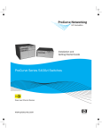
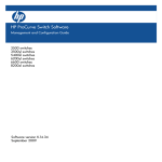
HP ProCurve Switch 8200zl/5400zl/3500 Series
Ordering Guide
Part 1: zl series chassis power
supply selection (PoE)
The HP ProCurve Switch 8200zl/5400zl/3500
series can power any device that adheres to the IEEE
802.3af (PoE) standard; additionally, the 8200zl and
5400zl series can power any device that adheres
to the IEEE 802.3at (PoE+) standard. The switches
will automatically detect how much power is needed
when a compatible device is plugged into the port.
Throughout this document, PoE and PoE+ will be
referred to as PoE, except where there are distinct
differences between PoE and PoE+ functionality.
The internal power supply for the HP ProCurve 3500
series switches provides both the system power and
PoE power. There are three different power supplies
available for the HP ProCurve Switch 8200zl/5400zl
series. These power supplies provide system power
(the power needed to run the switch itself) and PoE/
PoE+ power (the power sent down the Ethernet cable
to power the device at the other end). The difference
between the power supplies is the amount of PoE
power or PoE+ power available from the supply.
Power
supply
12 V
system
power
50 V
PoE
power
54 V
PoE+
power
Power
supply
total
J8712A
100–127 V
200–240 V
600 W
600 W
273 W
273 W
–
–
875 W
875 W
J8713A
200–240 V
600 W
900 W
–
1500 W
J9306A
110–127 V
200–240 V
600 W
600 W
–
–
300 W
900 W
900 W
1500 W
These differences will be discussed in Step 4 of the
procedure following.
2
It is important to plan for peak PoE power needs
so that sufficient power is available in the switch.
When the peak power needs of the powered devices
(PDs) connected to the switch exceed the PoE power
available from the supplies, the PoE power priority in
the switch is used to determine which ports lose PoE
power. Consult the switch manual for a discussion of
the PoE power priority capability. Ports that lose their
PoE power will not be powered again to prevent them
from turning on and off, unless the loss of power was
due to a power supply failure. To avoid this situation,
use this guide to correctly size the power supplies.
Choosing the number and type of supplies that are
best for your solution is a four-step process.
Step 1: Determine your initial PoE
power needs
Count the number of PDs and the PoE peak power
each consumes. The actual peak power needed
by a powered device should be available in the
documentation or data sheet for that device. The
8200zl, 5400zl, and 3500 series switches can
allocate actual PD power rounded up to the nearest
watt. Add up the total wattage needed. Also add
22 W for each PoE and PoE+ module in the chassis.
The first PD plugged into each module will release 17
W of this module’s allotment back to the switch PoE
power pool. For this reason, it is recommended to
have at least one PD plugged into each PoE module
as PDs are added to the switch.
Table 1. Use this table to determine your PoE power needs from Steps 1 and 2.
Power-consuming items
Powered devices at each wattage:
Power needed
_____
_____
_____
_____
_____
_____
_____
_____
_____
_____
_____
_____
_____
_____
_____
_____
_____
_____
_____
_____
_____
_____
_____
_____
_____
_____
_____
_____
_____
_____
x
x
x
x
x
x
x
x
x
x
x
x
x
x
x
x
x
x
x
x
x
x
x
x
x
x
x
x
x
x
1W=
2W=
3W=
4W=
5W=
6W=
7W=
8W=
9W=
10 W =
11 W =
12 W =
13 W =
14 W =
15 W =
16 W =
17 W =
18 W =
19 W =
20 W =
21 W =
22 W =
23 W =
24 W =
25 W =
26 W =
27 W =
28 W =
29 W =
30 W =
________
________
________
________
________
________
________
________
________
________
________
________
________
________
________
________
________
________
________
________
________
________
________
________
________
________
________
________
________
________
W
W
W
W
W
W
W
W
W
W
W
W
W
W
W
W
W
W
W
W
W
W
W
W
W
W
W
W
W
W
Subtotal: ________ W
# of PoE modules in switch without a PD
plugged in
_____ x 22 W =
________ W
# of PoE modules in switch with a PD
plugged in
_____ x 5 W =
________ W
Subtotal: ________ W
Future PoE wattage desired
Subtotal: ________ W
Total watts needed: _________ W
Step 2: Determine your future PoE
power needs
PoE power: If you would like to plan for future PoE
power needs now, determine how much extra PoE
power you might need. Add this wattage to your
figure from Step 1.
3
Table 2. Redundant power definitions
No redundancy
No power is held in reserve. For system power, if a power supply fails, some or all parts of the switch become
inoperative. For PoE power, all power supplied by the available supplies can be used to power PDs. If a power supply
fails, the amount of PoE power supplied by the failed supply is no longer available. The switch will turn off the number
of PDs starting with the lowest PoE priority PD up to the wattage lost with the failed supply.
N+1 redundancy
For system power, one supply can fail and the entire switch remains functional. For PoE power, one power supply can
fail without loss of power to any currently powered device. Under N+1, the switch will hold in reserve (not use) the
amount of PoE power equal to the largest PoE supply. If a power supply fails, the reserve power is used to continue to
power all PDs without interruption. N+1 redundancy may not protect against a failed external power main.
Full redundancy
For system power, one-half of the power supplies can fail and the entire switch remains functional. For PoE power,
one-half of the power supplies can fail without power interruption to any connected nodes. The switch will hold at
least one-half of the PoE power available from all supplies in reserve to be used in case of power supply failures. Full
redundancy would be used if protection from a failed external power main is desired.
Step 3: Determine the required level
of redundant power
See Table 2 for definitions of the various levels
of redundancy.
No redundancy: Skip to Step 4.
System power redundancy: System power is the
power needed to run the switching and routing
functionality in the switch—essentially everything
except PoE. One power supply is sufficient for full
system power for HP ProCurve Switch 5406zl/8206zl
systems; two power supplies are required for
HP ProCurve Switch 8212zl/5412zl systems. Full
system power redundancy is achieved with two power
supplies for the 5406zl/8206zl systems and four
power supplies for the 8212zl/5412zl systems.
Since there are only two power supply slots
in 8206zl/5406zl chassis, system power N+1
redundancy and full redundancy are equivalent.
8212zl/5412zl systems can have system power
N+1 with three supplies and full redundancy with
four supplies.
PoE power redundancy: PoE wattage is the power
necessary to power the external PDs connected to the
switch. PoE power is independent from system power
and is not used in powering the normal functions of
the switch.
Determine the level of PoE power redundancy you
desire. Table 2 has definitions for the different types of
redundant power.
4
With software version K13.01 or later, the switch can
be configured to automatically hold PoE power in
reserve based on the desired level of redundancy.
With prior software versions, the switch does not
automatically hold any PoE power in reserve for
redundancy. To ensure PoE redundancy with prior
software versions, plan for the amount of power to be
held in reserve, and keep the wattage needed for the
level of redundancy desired in reserve by controlling
the number of PDs on the switch.
For No redundancy: On failure of one power
supply, PDs using PoE power equal to the PoE power
available from the largest supply installed will have
their PoE power turned off as the power supply losing
power goes down. If after several seconds the switch
determines that there is excess PoE power available
with the remaining supply or supplies, the number of
ports that can be turned back on—using the excess
power available—will have their power restored.
For N+1 redundancy: For software version K13.xx
or later, configure the switch to enforce N+1
redundancy. For prior software versions, hold in
reserve the amount of PoE power available in the
highest-powered power supply.
For Full redundancy: For software version K13.xx or
later, configure the switch to enforce full redundancy.
For prior software versions, hold half the amount of
PoE power available in reserve if all power supplies
in the switch provide the same level of PoE power.
Determine full redundancy reserve power when
unlike power supplies are installed by separating the
installed power supplies into two columns so the total
power in each column is as close in value as possible.
Hold in reserve the amount of power from the column
with the larger added power.
Step 4: Choose your power supply
or supplies
There are three power supplies available for the
HP ProCurve Switch 8200zl and 5400zl series.
See Table 4 for the minimum and maximum power
supply counts for the various zl switches.
Table 4. Switch power supply capacities
Included
supplies
Min.
# of
supplies
needed
Max.
# of
supplies
possible
Max.
# of
supplies
with the
power
shelf
Table 3. HP ProCurve Switch zl power supplies
Product
number
Supply
System
power
PoE
power
Power main
requirements
J8712A
HP ProCurve
Switch zl 875 W
Power Supply
600 W
273 W
110 V @ 12 A
220 V @ 5.5 A
J8713A1
HP ProCurve
Switch zl 1500 W
Power Supply
600 W
900 W
220 V @ 10 A
only
HP ProCurve
1500 W PoE+ zl
Power Supply
600 W
600 W
J9306A
1
300 W
900 W
110 V @ 13 A
220 V @ 10 A
se of the J8713A changes the switch altitude specification from 4.6 km (15,000 ft)
U
to 3.1 km (10,000 ft).
PoE power available from the power supplies is
computed by adding the PoE power from all of the
installed supplies. If PoE power redundancy is desired,
take into account the amount of PoE power that needs
to be held in reserve when calculating power needs.
Product
number
J8697A
5406zl
chassis
None
1
2
4
J8699A
5406zl-48G
1
875 W
1
2
4
J9447A
5406zl-48GPoE+
1 PoE+
1
2
4
J8698A
5412zl
chassis
None
2
4
6
J8700A
5412zl-96G
2
875 W
2
4
6
J9448A
5412zl-96GPoE+
2 PoE+
2
4
6
J9475A
8206zl base
system
None
1
2
4
J8715A
8212zl base
system
None
2
4
6
J9091A
8212zl
chassis only
(replacement)
None
2
4
6
Mixing the J8712A and/or the J8713A power supplies
with the J9306A in the same chassis is not supported.
Though installing the J8712A and J8713A power
supplies in the same chassis is a supported
configuration, it is strongly discouraged—particularly
if some level of PoE power redundancy is wanted—
since the amount of PoE power available upon power
supply loss may not be intuitive.
For example, if full PoE power redundancy is wanted
using 875 W and 1500 W power supplies, the
1500 W supply should be held in reserve. This would
mean that only 273 W of PoE power should be used
normally. While it is tempting to add the two supplies
and divide by two (using 585 W and keeping 585 W
in reserve), if power is lost from one supply, the full
900 W of the 1500 W supply may be missing, with
only the 273 W of the 875 W supply available. This
is obviously not enough to keep the 585 W of the
normal environment up and running. Thus, there is no
redundancy for some of the PDs in this scenario, even
though that was desired. Proper power redundancy
can be provided by uniformly employing power
supplies of equivalent power capacity.
HP ProCurve
switch
product
Watch the amount of power drawn from the building
power mains by the installed switch supplies. It adds
up quickly. Refer to Table 1 for incoming power
requirements. If power redundancy is very important,
split the available power supplies between two
separate building circuits. If one power main goes
down, you will still have the other one to power
the switch.
Note that the J8713A 1500 W supply is 200 to
240 V only.
PoE power levels
There are four PoE power levels defined by the PoE
IEEE 802.3af standard.
Table 5. IEEE 802.3af power classes
IEEE 802.3af class
Power
0 (default)
15.4 W
1
4W
2
7W
3
15.4 W
4
30 W (PoE+)
Cisco pre-standard
6.3 W
5
Power cords
3500-24-PoE, the internal power supply can power
all 24 ports at 15.4 W for PoE. The additional power
The power cords available for these switches are sized
available from the HP ProCurve 620 RPS/EPS provides
for the increased current that can be drawn to meet
full redundancy for the PoE power.
the needs of PoE. As a result, they are uncommon and
it is recommended to have a few spares on hand. For If the HP ProCurve 620 RPS/EPS is connected to a
more details, see Part 3 for the listing of power cords. HP ProCurve Switch 3500yl-48G-PWR or HP ProCurve
Switch 3500-48-PoE, it allows all 48 ports to run at
Using power cords not rated to carry the current
the full 15.4 W simultaneously but with no PoE power
drawn by a device could create a fire hazard. Use
redundancy. The additional PoE power from the
the proper power cord listed for your HP ProCurve
HP ProCurve 620 RPS/EPS could be used to provide
equipment. Elevated operational temperatures reduce
full PoE power redundancy for 24 of the 48 ports, if
the amount of current that power cords can safely
that is needed, rather than additional power for the
provide. The cords listed in Part 3 have been certified
extra ports.
by HP ProCurve Networking to be adequate for the
rated operating temperature range of our products,
HP ProCurve Switch zl Power
and use of any other power cord is not supported by
Supply Shelf
HP ProCurve.
HP ProCurve 620 Redundant/
External Power Supply (RPS/EPS)
The HP ProCurve 620 Redundant/External Power
Supply (J8696A) provides RPS and EPS power
individually to two HP ProCurve 3500 series switches
or RPS to two HP ProCurve 6200yl or HP ProCurve
2900 series switches. The HP ProCurve 620 RPS/EPS
does not support the HP ProCurve Switch 8200zl or
5400zl series.
RPS power: Connecting the RPS provides full
redundancy for the connected switch’s system power.
EPS power: The HP ProCurve 620 RPS/EPS provides
398 W of additional PoE power to each of two
connected HP ProCurve 3500 series switches. For an
HP ProCurve Switch 3500yl-24G-PWR or HP ProCurve
6
The HP ProCurve Switch zl power supply shelf
(J8714A) provides two additional power supply
bays for connection to one or two zl switches. By
using the power supply shelf to provide extra EPS
(PoE) power to the zl switch, the extra PoE power can
be used to power additional PDs beyond what can
be powered by the internal switch supplies or, more
commonly, to provide for larger redundant PoE power
environments, such as large VoIP installations.
The power supply shelf accepts the same power
supplies available for the zl switches and connects
to the switches via 2 m EPS cables included with the
power supply shelf. The extra PoE power available
via the power supply shelf is determined by the
power supplies installed in the Shelf. See the
HP ProCurve Switch zl Power Supply Shelf data
sheet for more details.
Part 2: Software
licenses
To enable Advanced Routing feature set, please order
the Premium License specific to the switch series:
The HP ProCurve Switch 8200zl, 5400zl, and 3500
series use the same software image base and ship
with Intelligent Edge and IP-based routing feature sets
standard. For these switches, an optional Premium
License is available to enable Advanced Routing
features. NOTE: Legacy HP ProCurve Switch 8212zl
(J8715A) products were shipped with Advanced
Routing features standard—no Premium License
upgrade is required for these switches. For a detailed
listing of these functionalities, please see the data
sheets for the HP ProCurve Switch 8200zl, 5400zl,
and 3500 series on our website at:
www.procurve.com.
• 5400zl series: J8994A—HP ProCurve Switch 5400zl
Premium License
Additional features might be required for deployments
in the aggregation/distribution layer or if full routing
is required in the wiring closet (see Figure 1). To meet
these requirements, HP ProCurve provides the Premium
License that contains the following features:
HP ProCurve Manager (PCM) or ProCurve Manager
Plus can be used to simplify the process of adding
licenses. Just provide the registration ID from the
Premium License and tell PCM onto which switch to
install the license. PCM will communicate with the
MyProCurve Portal directly and add the license to the
switch without user intervention.
• OSPF
• PIM Sparse
• PIM Dense
• VRRP
• Q-in-Q (IEEE 802.1ad)
• 8200zl series: J9474A—HP ProCurve Switch 8200zl
Premium License
• 3500 series: J8993A—HP ProCurve Switch 3500
Premium License
Each Premium License product provides license-to-use
for a single 8200zl/5400zl/3500 series switch. Each
license can be added to the switch manually through
the MyProCurve Portal website using the registration
ID included with the Premium License, along with some
information obtained from the switch. The portal will
then provide a license key that is entered into the
switch and will enable the features.
A previously installed license can be removed from
an 8200zl, 5400zl, or 3500 series switch and
transferred to another switch within the same
product series.
While all 8200zl, 5400zl, and 3500 series switches
include Routing Information Protocol (RIP) that could be
used to route IP traffic, OSPF is a better choice in all
but the smallest environments. RIP is primarily used to
provide a way to get network traffic from one VLAN
to another in small environments.
7
Figure 1: Edge and aggregation/distribution use models
Aggregation/
Distribution
Aggregation/
Distribution
Edge
Edge
Edge
Edge
Software updates1 for existing
customers
In keeping with the longstanding value from
HP ProCurve Networking, software updates when
provided will be free of charge to existing customers.
Part 3: Fieldreplaceable units
The HP ProCurve Switch 5400zl management module
and fan tray are field-replaceable. For the Switch
8200zl series, the management modules, fan tray,
fabric modules and system support module (SSM)
are field-replaceable. The switches are covered by
the ProCurve Lifetime Warranty♦ with next-businessday replacement. Onsite spares stocking is strongly
encouraged to help ensure minimal downtime if a
management module or fan tray must be replaced.
In addition, rack-mounting kits are available for
HP 10000 Series four-post racks and other four-post
racks using the standard EIA unit of measurement.
All of these parts are available through the HP Parts
website (www.hp.com/buy/parts).
1
Spare management module
While past experience on other HP ProCurve
switches has shown an extremely low failure rate
on the management functionality, there may be
some customers who would like to have a spare
management module on hand. Upon failure, the
management module can be swapped out to restore
switch functionality.
Replacement management modules do not include
a CompactFlash unit as shipped by HP through the
HP Parts website. When replacing a management
module, customers should redeploy the CompactFlash
unit from the replaced module to “carry-over”
configuration files and switch software from the
previous module. A standalone CompactFlash (CF)
kit can be purchased separately.
Part number
HP ProCurve Switch 5400zl Management
Module (does not include CF card)
J8726-61001
HP ProCurve Switch 8200zl Management
Module (does not include CF card)
J9092A
Programmed CompactFlash Kit for 5400zl
Management Module
5070-1056
Programmed CompactFlash Kit for 8200zl
Management Module
5070-3051
oftware updates are done on a best-effort basis without commitment for
S
future functional enhancements.
♦ F or as long as you own the product, with next-business-day advance replacement (available in most countries). The following hardware products and their related series modules
have a one-year hardware warranty with extensions available: HP ProCurve Routing Switch 9300m series, HP ProCurve Switch 8100fl series, HP ProCurve Network Access
Controller 800, and HP ProCurve DCM Controller. The following hardware mobility products have a one-year hardware warranty with extensions available: HP ProCurve M111
Client Bridge, HP ProCurve MSM3xx-R Access Points, HP ProCurve MSM7xx Mobility and Access Controllers, HP ProCurve RF Manager IDS/IPS Systems, HP ProCurve MSM
Power Supplies, HP ProCurve 1 Port Power Injector, HP ProCurve CNMS Appliances, and HP ProCurve MSM317 Access Device. Disk drives in the HP ProCurve ONE Services
zl Modules, HP ProCurve Threat Management Services zl Module, and HP ProCurve MSM765zl Mobility Controller have a five-year hardware warranty. Standalone software,
upgrades, or licenses may have a different warranty duration. For details, refer to the ProCurve Software License, Warranty, and Support booklet at www.procurve.com/warranty.
8
Fan tray
Rack-mounting kit
HP ProCurve Switch 8200zl/5400zl series fan trays
can be hot-swapped without system disruption as long
as the new tray is installed within three minutes of the
previous tray being removed.
The switches normally ship with rack-mounting
“ears” that allow installation into a two-post, 19-inch
datacomm rack.
Replacing the HP ProCurve Switch 3500 or Switch
6200yl series fan tray requires that the switch be
removed from the rack, power removed, and the top
of the switch opened.
Part number
Two-Post Rack-Mounting Kit for Switch 5406zl
5069-8561
Two-Post Rack-Mounting Kit for Switch 5412zl
5069-8562
Switch 3500/6200yl Rack-Mounting Kit
5069-5705
Two-Post Rack-Mounting Kit for Switch 8206zl
5070-6865
Part number
Two-Post Rack-Mounting Kit for Switch 8212zl
5070-2983
HP ProCurve Switch 8206zl Fan Tray
J9476A
Switch zl Power Supply Shelf Rack-Mounting Kit
5070-3028
HP ProCurve Switch 8212zl Fan Tray
J9094A
HP ProCurve Switch 5406zl Fan Tray
J8697-60005
HP ProCurve Switch 5412zl Fan Tray
J8698-60005
HP ProCurve Switch 3500/6200yl Fan Tray
5069-8598
If installation using an HP 10000 Series four-post
19-inch cabinet is desired, a rack-mounting kit is
available providing rails that give sturdy support for
the switch along its entire length.
Spare 8200zl fabric module
HP ProCurve Switch 8200zl series base systems ship
with required fabric modules, but spare modules can
be ordered to be on hand in the event of a failure.
One fabric module is required, and replacement
fabric modules can be swapped out during switch
operation with minimal interruption to switch service.
Part number
HP ProCurve Switch 8200zl Fabric Module
Part number
For 8200zl/5400zl—10K Rack Rail Kit Assembly
5070-0145
For 3500/6200yl—10K Rack Rail Kit Assembly
356578-B21*
* Ordered through your HP sales channel
For transporting switches in a rack, please see the
Installation Guide that is included with the rack rail kits
for more instructions.
J9093A
Spare 8200zl system support module
The HP ProCurve Switch 8200zl series requires a
system support module (SSM), and spare modules
can be ordered because this module is a critical
system component. The spare SSM ships with the tool
required for removal of the SSM from the 8200zl
chassis, and replacement should be done during a
scheduled maintenance window because the SSM is
not a hot-swappable component.
Part number
HP ProCurve Switch 8200zl System Support
Module
J9095A
9
RPS/EPS and console cables
The HP ProCurve 620 Redundant/External Power
Supply (J8696A) and the HP ProCurve Switch zl Power
Supply Shelf (J8714A) use cables to individually
connect the RPS (620 only) and EPS (PoE) power to the
target HP ProCurve 8200zl/5400zl or 3500/6200yl
series switches. The same cable is used for either RPS
or EPS power. The HP ProCurve 620 RPS/EPS comes
with four of these cables and the power supply shelf
comes with two, which are the respective maximum
number of cables usable for each of these units. If a
spare cable is desired, use the product number in the
following table.
Note: Even though the RPS/EPS cables are
interchangeable between the HP ProCurve 620
and Switch zl power supply shelf, the 620 does
not support 8200zl/5400zl series switches, while
the Power Supply Shelf works only with
8200zl/5400zl switches.
HP ProCurve Switch
3500/6200yl Series
HP ProCurve 620
Red/Ext Power
Supply (J8696A)
Australia/
New Zealand
8120-5335
8121-0871
China
8120-8385
8121-0916
Continental Europe
8120-5336
8120-6352
Denmark
8120-5340
8120-6897
Israel
8121-1009
8121-1010
Japan
8120-5342
8121-09421
8120-69032
South Africa/India
8120-5341
8121-0915
Switzerland
8120-5339
8121-0916
Taiwan
8121-0967
8121-0968
Thailand
8121-0671
8121-0922
U.K.
8120-5334
8121-0907
Hong Kong/Singapore
8120-5334
8121-0907
U.S./Canada/Mexico
8121-0973
8120-6361
1
100 V cord: ships standard with the 620 after April 1, 2007
2
200 V cord: ships standard with the 620 prior to April 1, 2007
Part number
Switch zl and yl RPS/EPS cable
5070-0102
DB9-DB9 Console cable for 5400zl Series
5184-1894
RJ45-to-DB9 Console cable for 8200zl Series
5188-6699
Power cords
The power cords available for these switches are
sized for the increased current that can be drawn to
meet the needs of PoE. As a result, these power cords
may not be found in a typical environment, and
power cords “borrowed” from other products will not
work in most instances. Having some spare power
cords on hand may be a good idea. They can be
purchased through the HP Parts website:
www.hp.com/buy/parts.
10
HP ProCurve Switch 8200zl/5400zl Series
and
HP ProCurve Switch zl Power Supply Shelf
(J8714A)
Australia/
New Zealand
1500 W
PoE+ Supply
875 W
Supply
1500 W
Supply
8121-0857
8121-0857
8121-0871
China
8121-1034
8121-1034
8121-0924
Continental Europe
8120-5336
8120-5336
8120-6899
Denmark
8120-5340
8120-5340
8120-6897
Israel
8121-1009
8121-1009
8121-1010
Japan
8120-5342
8120-5342
8120-6903
South Africa/India
8120-5341
8120-5341
8121-0915
Switzerland
8120-5339
8120-5339
8120-6897
Taiwan
8121-0941
8121-0941
8120-6903
Thailand
8121-0671
8121-0671
8121-0675
U.K.
8120-5334
8120-5334
8120-6898
Hong Kong/Singapore
8120-5334
8120-5334
8120-6898
U.S./Canada/Mexico
8121-0973
8121-0973
8120-6903
Jumper cables (PDU to product)
If power interconnects between a switch and a power
distribution device, such as a power distribution
unit (PDU) or an uninterruptible power supply
(UPS) is desired, jumper cables are available. The
jumper cables for these switches are sized for the
increased current that can be drawn to meet the
needs of PoE. As a result, these jumper cables meet
the environmental and electrical specifications of
HP ProCurve switches. Jumper cables “borrowed”
from other products will not work in most instances.
The jumper cables can be purchased through the
HP Parts website: www.hp.com/buy/parts.
HP ProCurve 8200zl/5400zl
Switch and HP ProCurve Switch
zl Power Supply Shelf (J8714A)
Length
(meters)
1500 W PoE+
or 875 W Supply1
1500 W
Supply2
Australia/
New Zealand
1m
2.5 m
8121-1093
8121-1094
8121-1089
8121-1090
China
1m
2.5 m
8121-1093
8121-1094
8121-1089
8121-1090
Continental Europe
1m
2.5 m
8121-1093
8121-1094
8121-1089
8121-1090
Denmark
1m
2.5 m
8121-1093
8121-1094
8121-1089
8121-1090
Israel
1m
2.5 m
8121-1093
8121-1094
8121-1089
8121-1090
Japan
1m
2.5 m
8121-1092
8121-1091
8121-1089
8121-1090
South Africa/India
1m
2.5 m
8121-1093
8121-1094
8121-1089
8121-1090
Length
(meters)
HP ProCurve
Switch
3500/6200yl
Series1
HP ProCurve
620 Red/Ext
Power Supply
(J8696A)2
Australia/
New Zealand
1m
2.5 m
8121-1093
8121-1094
8121-1089
8121-1090
Switzerland
1m
2.5 m
8121-1093
8121-1094
8121-1089
8121-1090
China
1m
2.5 m
8121-1093
8121-1094
8121-1089
8121-1090
Taiwan
1m
2.5 m
8121-1092
8121-1091
8121-1089
8121-1090
Continental Europe
1m
2.5 m
8121-1093
8121-1094
8121-1089
8121-1090
Thailand
1m
2.5 m
8121-1093
8121-1094
8121-1089
8121-1090
Denmark
1m
2.5 m
8121-1093
8121-1094
8121-1089
8121-1090
U.K.
1m
2.5 m
8121-1093
8121-1094
8121-1089
8121-1090
Israel
1m
2.5 m
8121-1093
8121-1094
8121-1089
8121-1090
Hong Kong/Singapore
1m
2.5 m
8121-1093
8121-1094
8121-1089
8121-1090
Japan
1m
2.5 m
8121-1092
8121-1091
8121-1089
8121-1090
U.S./Canada/Mexico
1m
2.5 m
8121-1092
8121-1091
8121-1089
8121-1090
South Africa/India
1m
2.5 m
8121-1093
8121-1094
8121-1089
8121-1090
Switzerland
1m
2.5 m
8121-1093
8121-1094
8121-1089
8121-1090
Taiwan
1m
2.5 m
8121-1092
8121-1091
8121-1089
8121-1090
Thailand
1m
2.5 m
8121-1093
8121-1094
8121-1089
8121-1090
U.K.
1m
2.5 m
8121-1093
8121-1094
8121-1089
8121-1090
Hong Kong/Singapore
1m
2.5 m
8121-1093
8121-1094
8121-1089
8121-1090
U.S./Canada/Mexico
1m
2.5 m
8121-1092
8121-1091
8121-1089
8121-1090
1
14 to C15 cable: The C15 connector connects into the power inlet on the switch
C
power supply, while the C14 connector connects into a receptacle on a power
distribution device.
2
19 to C20 cable: The C19 connector connects into the power inlet on the switch
C
power supply, while the C20 connector connects into a receptacle on a power
distribution device.
11
Technology for better business outcomes
To learn more, visit www.hp.com/go/procurve
© Copyright 2007, 2009 Hewlett-Packard Development Company, L.P. The information contained herein
is subject to change without notice. The only warranties for HP products and services are set forth in
the express warranty statements accompanying such products and services. Nothing herein should be
construed as constituting an additional warranty. HP shall not be liable for technical or editorial errors or
omissions contained herein.
4AA1-2038ENW Rev. 2, September 2009