1
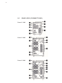
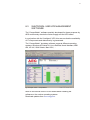
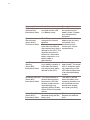
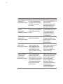
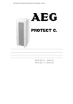
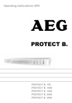
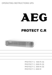
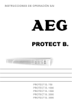
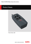
OPERATING INSTRUCTIONS Protect C Protect C.1000 Protect C.2000 Protect C.3000 EN 2 3 Thank you for purchasing the AEG UPS PROTECT C from AEG Power Solutions. Safety information and operating instructions are included in this manual. To ensure correct use of the UPS, please read this manual thoroughly before operating it. Use this manual properly. 4 CONTENT 1. Notes on these Operating Instructions .................. 6 2. General Information ................................................... 8 2.1 Technology ................................................................... 8 2.2 System Description ....................................................... 9 2.3 Technical information .................................................. 11 3. Safety ........................................................................ 16 3.1 General Safety Instructions ......................................... 16 3.2 Safety Instructions for Protect C ................................. 17 3.3 CE-Certificate.............................................................. 20 4. Set-Up and Operation .............................................. 21 4.1 Unpacking and Inspection ........................................... 21 4.2 Point of Installation...................................................... 22 5. Overview Connections, Operating / Display Elements ................................................................... 23 5.1 Front View ................................................................... 23 5.2 Rear View (Connections) ............................................ 24 6. Commissioning ........................................................ 26 6.1 6.2 6.3 6.4 Mechanical Set-Up...................................................... 26 External Battery Extension .......................................... 27 Power Supply .............................................................. 28 Consumer Connection ................................................ 29 7. Operation and usage ............................................... 31 7.1 Initial Installation ......................................................... 31 7.1.1 Switching on UPS ............................................... 31 7.1.2 Switching off UPS ............................................... 31 7.2 Control Panel .............................................................. 32 7.2.1 Overview ............................................................. 32 7.2.2 Indicators (LEDs) ................................................ 32 7.2.3 Operating (Navigation) ........................................ 33 7.3 Display (Main Menu) ................................................... 34 7.3.1 UPS Status Display ............................................. 34 7.3.2 Event Log ............................................................ 38 7.3.3 Measurements .................................................... 39 5 7.3.4 Control ................................................................ 39 7.3.5 Identification ........................................................ 40 7.3.6 Settings ............................................................... 41 8. Interfaces and communication ............................... 46 8.1 8.2 8.3 8.4 RS232 and USB Computer Interfaces ........................ 46 Communication slot .................................................... 46 Shutdown- und UPS Management Software ............. 47 EPO (Emergency Power Off) ...................................... 48 9. Trouble Shooting ..................................................... 49 9.1 Malfunctions ................................................................ 49 9.1.1 Alarm- / Error messages ..................................... 49 10. Maintenance ............................................................. 54 10.1 Battery Charging ......................................................... 54 10.2 Maintenance ............................................................... 54 10.2.1 Visual Check ....................................................... 54 10.2.2 Checking the Battery ........................................... 55 10.2.3 Fan Checking ...................................................... 55 10.3 Battery replacement .................................................... 55 11. Storage, Dismantling and Disposal ....................... 57 11.1 Storage ....................................................................... 57 11.2 Dismantling ................................................................. 57 11.3 Disposal ...................................................................... 57 12. Glossary .................................................................... 59 12.1 Technical Terms ......................................................... 59 12.2 Key Word Register ...................................................... 61 6 1. NOTES ON THESE OPERATING INSTRUCTIONS DUTY TO PROVIDE INFORMATION These operating instructions will help you to install and operate the Uninterruptible Power Supply (UPS) PROTECT C.1000, PROTECT C.2000 or PROTECT C.3000 as well as the associated external battery units PROTECT C.1000 BP or PROTECT C.2030 BP – all referred to as PROTECT C in this document – safely and properly, and for its intended purpose. These operating instructions contain important information necessary to avoid dangers during operation. Please read these instructions carefully prior to commissioning! THESE OPERATING INSTRUCTIONS ARE A COMPLETE PART OF THE PROTECT C The owner of this unit is obliged to communicate the full content of these operating instructions to all personnel transporting or starting the PROTECT C or performing maintenance or any other work on the unit. VALIDITY These operating instructions comply with the current technical specifications of the PROTECT C at the time of delivery. The contents do not constitute a subject matter of the contract, but serve for information purposes only. WARRANTY AND LIABILITY We reserve the right to alter any specifications given in these operating instructions, especially with regard to technical data and operation, prior to start-up or as a result of service work. Claims in connection with supplied goods must be submitted within one week of receipt, along with the packing slip. Subsequent claims cannot be considered. The warranty does not apply to damage caused by non-compliance with these instructions (such damage also includes damaging the warranty seal). AEG will accept no liability for consequential damage. AEG reserves the right to rescind all obligations such as warranty agreements, service contracts, etc. entered into by AEG and its representatives without prior notification in the event of maintenance and repair work being carried out with anything other than original AEG spare parts or spare parts purchased by AEG. 7 HANDLING PROTECT C is designed and constructed so that all necessary steps for start-up and operation can be performed without any internal manipulation of the unit. Maintenance and repair work may only be performed by trained and qualified personnel. Illustrations are provided to clarify and facilitate certain steps. If danger to personnel and the unit cannot be ruled out in the case of certain work, it is highlighted accordingly by pictograms explained in chapter 3. HOTLINE If you still have questions after having read these operating instructions, please contact your dealer or our “Hotline”: Tel: +49 2902 763100 Internet: www.aegps.com COPYRIGHT No part of these operating instructions may be transmitted, reproduced and/or copied by any electronic or mechanical means without the express prior written permission of AEG. © Copyright AEG 2014. All rights reserved. 8 2. GENERAL INFORMATION 2.1 TECHNOLOGY PROTECT C is an Uninterruptible Power Supply (UPS) for essential loads such as PCs, workstations, servers, network components, telecommunication equipment and similar devices. It consists of: Mains filter with surge voltage protection (device protection/ class D) and mains energy backfeed protection Rectifier section with PFC logic (power factor correction unit) Separate battery charger with switch mode power supply technology Sealed, maintenance-free battery system as energy storage medium with downstream DC/DC converter unit IGBT inverter for continuous supply of connected loads with sinusoidal AC voltage Automatic bypass as additional passive redundancy Control unit based on digital signal processor technology 9 2.2 SYSTEM DESCRIPTION The UPS is connected to a shockproof socket between the public utility’s mains and the loads to be protected. The power section of the rectifier converts the mains voltage to DC voltage for supplying the inverter. The circuit technology used (PFC) enables sinusoidal current consumption and therefore operation with little system disturbance. A separate, second rectifier (charging REC set up using switch mode power supply technology) is responsible for charging or trickle-charging the battery connected in the intermediate circuit. The configuration of this charging REC means the harmonic content of the charging current for the battery is almost zero, so the service life of the battery is increased even more. The inverter is responsible for converting the DC voltage into a sinusoidal output voltage. A microprocessor-controlled control system based on pulsewidth modulation (PWM) in conjunction with an extremely quickly pulsating IGBT power semiconductors of the inverter guarantee that the voltage system on the protected busbar is of the highest quality and availability. In the event of mains faults (e.g. power outage), the voltage continues to be supplied from the inverter to the load without any interruption. From this point onwards, the inverter draws its power from the battery instead of the rectifier. No switching operations are necessary; this means there is no interruption in the supply to the load. 10 The automatic bypass serves to increase the reliability of the supply further. It switches the public mains directly through to the load if there is an inverter malfunction. As a result, the automatic bypass represents an extra passive redundancy for the load. The graphical LC display used provides for versatile use and easy operation. Such a convenient feature as an emergency power off contact round out the standard interface selection (USB, RS232, communication slot). 11 2.3 TECHNICAL INFORMATION Power rating Protect C.1000 1000 VA (cos φ = 0.8 lag.) 800 W Protect C.2000 2000 VA (cos φ = 0.8 lag.) 1600 W Protect C.3000 3000 VA (cos φ = 0.8 lag.) 2400 W UPS Input 1ph~ / N / PE Rated input voltage 200 / 208 / 220 / 230 / 240 VAC Rectifier voltage range (without battery 176 – 300 VAC operation, 100 % load, cos = 0.8 lag.) Rectifier voltage range (without battery operation, 110 – 300 VAC 50 % load, cos = 0.8 lag.) 50 Hz / 60 Hz Nominal frequency (autom. detection or manual) Frequency tolerance ±10 % Power consumption at full load (max.) Protect C.1000 Protect C.2000 Protect C.3000 4.8 / 4.6 / 4.4 A UN = 220 / 230 / 240 VAC 8.9 / 8.5 / 8.2 A UN = 220 / 230 / 240 VAC 13.1 / 12.5 / 12.0 A UN = 220 / 230 / 240 VAC Bypass voltage range 176 VAC – 264 VAC Mains feedback factor ≥0.99 (THDi <5 %) Connection IEC connector UPS Output Rated output voltage Nominal frequency 200 / 208 / 220 / 230 / 240 VAC ±2 % Power reduction at 200 VAC 20 % / at 208 VAC 10 % 50 Hz / 60 Hz ±0.2 Hz (Tolerance in battery mode or free running in variable-frequency inverter mode) Synchronization range 50 Hz / 60 Hz ±10 % Synchronization speed 1 Hz/s 12 Power factor range Inverter frequency Sinus waveform 0.3 lag. to 0.9 cap. at full output Power reduction of 20 % to 0.5 cap. 40 % power reduction (Bypass disabled, Input Frequency Range 40 - 70 Hz) Sinus waveform distortion <3 % THD (linear load) <5 % THD (non-linear load) Connection IEC sockets Crest factor 3:1 Overload behaviour up to 105 % continuous; >105 % – <110 % for 60 s; ≥110 % – <125 % for 30 s; ≥125 % – 150 % for 10 s; Then automatic inverter to Bypass in < 4 ms (switches back when overload damps = Load < 90%) Overload bypass Up to 125 % continuous >125 % – 150 % 10 min. Short circuit 3 x IN for 100 ms Battery Autonomy Time External battery module cos = 0.8 lag. / 100 % charged battery C.1000 C.2000 C.3000 With integrated battery 4.5 min. 7 min. 3.5 min. 1 add. battery module 25 min. 38,5 min. 21 min. 2 add. battery modules 51 min. 70 min. 45 min. Battery check (programmable) daily; weekly; monthly Rated DC voltage (intermediate circuit) Protect C.1000 36 VDC Protect C.2000 96 VDC Protect C.3000 96 VDC Battery charging current (max.) 1 ADC 13 Battery type Recharge time (to 90 % of rated capacity) sealed maintenance free (VRLA) Protect C.1000 12 V 7 Ah x 3 Protect C.2000 12 V 7 Ah x 8 Protect C.3000 12 V 7 Ah x 8 Protect C.1000 BP 12 V 7 Ah x 3 x 2 Protect C.2030 BP 12 V 7 Ah x 8 x 2 ~ 8 h (UPS with internal battery) ~ 24 h (with 1 additional battery) ~ 40 h (with 2 additional batteries) Communication Interfaces RS232 SUB-D (9-pin), USB Additional: communication slot for Extensions (eg, relay card, SNMP (Pro), ...) Remote shutdown contact Potential-free (optionally programmable as opener or closer) Shutdown Software “CompuWatch” for all popular operating on CD systems like:. Windows, Linux, Mac, Unix, Novell, Sun General data Classification Full load efficiency (AC-AC / DC-AC) Full load efficiency (ECO / Transfer time <10 ms) (economical mode) Inherent noise (1 m distance) VFI SS 111 acc. to. IEC 62040–3 double conversion technology (INV / BATT) VFI SS 311 acc. to IEC 62040–3 ECO mode Protect C.1000 ≥87 % / ≥85 % Protect C.2000 ≥88 % / ≥85 % Protect C.3000 ≥88 % / ≥85 % Protect C.1000 ≥93 % Protect C.2000 ≥94 % Protect C.3000 ≥94 % Protect C.1000 Protect C.2000 Protect C.3000 ≤44 dB (A) ≤49 dB (A) ≤49 dB (A) Type of cooling Forced cooling by variable speed fans Operating temperature 0 °C to 45 °C Recommendation +15 °C to +25 °C (due to battery system) -15 °C to +60 °C (UPS) 0 °C to +35 °C (Battery) Storage temperature 14 Humidity 0 – 95 % (non-condensing) Max. site altitude Up to 1000 m rated power Usage >1000 m above sea level results in a derating as follows: Height (m) 1000 1500 2000 2500 3000 Power (%) 100 95 90 85 80 Protection IP20 Outlets Protect C.1000 4 x IEC 320 C13 Protect C.2000 6 x IEC 320 C13 Protect C.3000 Display Equipment color 4 x IEC 320 C13 +1 x IEC 320 C19 +1 fixed connection on terminal block Graphic LCD, resolution: 128 x 64 pixels Languages: DE / EN / ES / FR / RU 3 LEDs for power indication Blackline Weight (net / gross) Protect C.1000 Dimensions W x H x D (net) 13 kg / 15 kg Protect C.1000 BP 18 kg / 19 kg Protect C.2000 31 kg / 33 kg Protect C.3000 31 kg / 33 kg Protect C.2030 BP 44 kg / 46 kg Protect C.1000 145 mm x 220 mm x 400 mm 145 mm x 220 mm x 400 mm 192 mm x 347 mm x 460 mm 192 mm x 347 mm x 460 mm 192 mm x 347 mm x 460 mm Protect C.1000 BP Protect C.2000 Protect C.3000 Protect C.2030 BP 15 Dimensions W x H x D (gross) (packaging) Guidelines Protect C.1000 240 mm x 330 mm x 495 mm Protect C.1000 BP 300 mm x 330 mm x 500 mm Protect C.2000 330 mm x 475 mm x 590 mm Protect C.3000 330 mm x 475 mm x 590 mm Protect C.2030 BP 330 mm x 475 mm x 590 mm The PROTECT D complies with the EN 62040 product standard. The CE seal on the device confirms that the device complies with the following directives: EG Low Voltage Directive 2014 / 35 / EU as well as the EMC Directive 2004 / 108 / EG for electromagnetic compatibility, if the installation instructions provided in this manual are followed. For 2014 / 35 / EU Low Voltage Directive Reference number EN 62040-1: 2008 For 2004 / 108 / EG EMC-Directive Reference number EN 62040-2: 2006 Class C1 16 3. SAFETY 3.1 GENERAL SAFETY INSTRUCTIONS Read these operating instructions prior to start-up of the PROTECT C UPS and its external battery modules (special accessories), and observe the safety instructions. Only use the unit if it is in a technically perfect condition and always in accordance with its intended purpose, while being aware of safety and danger aspects, and in accordance with the operating instructions! Immediately eliminate any faults that could be detrimental to safety. The following pictograms are used in these operating instructions to identify dangers and important information: Danger! Identifies risk of fatal injury to the operator. Attention! Identifies risk of injury and risk of damage to the unit and parts of the unit. Information! Useful and important hints for the operation of the UPS and its external battery modules (special accessories). 17 3.2 SAFETY INSTRUCTIONS FOR PROTECT C This chapter contains important instructions for the PROTECT C UPS and its external battery modules (special accessories). These must be followed during assembly, operation and maintenance of the uninterruptible power supply and the battery systems (internal and, if appropriate, external as well). The UPS carries high voltage. Danger! The unit may only be opened by trained and qualified personnel. Repairs may only be carried out by qualified customer service staff! The output may be live, even if the UPS is not connected to the mains, since the UPS has its own internal power supply (battery)! The equipment must be properly earthed in order to protect personnell! PROTECT C may only be operated with or connected to a 220 V / 230 V / 240 V mains with protective grounding using a CE marked mains connection cable with PE conductor (included in the delivery) that has been tested in accordance with national standards. Danger! Risk of burning! The battery has powerful short-circuit currents. Incorrect connection or isolation faults can lead to melting of the plug connections, sparking potential and severe burns! The unit has a warning signal that sounds when the battery voltage of PROTECT C is exhausted or when the UPS is not working in its normal mode (see also chapter 9.1.1, Page 49). 18 Observe the following safety instructions to ensure permanent operational safety of and safe work with the UPS and the battery modules (special accessories): Do not dismantle the UPS! (The UPS does not contain any parts that require regular maintenance. Bear in mind that the warranty will be invalidated if the unit is opened!) Do not install the unit in direct sunshine or in close proximity of heaters! The unit is designed to be installed inside in heated rooms. Never install the housing in the vicinity of water or in an excessively damp environment! Condensation may occur if the UPS is brought from a cold environment into the room where it is to be installed. The UPS must be absolutely dry prior to start-up. As a result, leave it to acclimatise for at least two hours. Never connect the mains input to the UPS output, and vice versa! Ensure that no fluids or foreign bodies can penetrate the housing! Do not block the air vents of the unit! Keep children away from the unit and ensure that objects are never inserted through the air vents! Do not connect household appliances such as hairdryers to the UPS! Also take care when working with motor loads. It is essential to avoid back-feeding the inverter, e.g. if the load is intermittently operated in regenerative mode. The mains connection should be near the unit and easily accessible to facilitate disconnecting the AC input or pulling out the plug! During operation, do not disconnect the mains connection cable from the UPS or from the socket outlet in the building (shockproof socket), otherwise the protective grounding of the UPS and all the loads connected to it will be cancelled. Danger! Electric shocks! Even after the mains voltage has been disconnected, the components within the UPS remain connected to the battery and can thus cause electric shocks. It is therefore imperative to disconnect the battery circuit before carrying out any maintenance or repair work! If it is necessary to replace the battery or carry out maintenance work, this must be done by or under the supervision of a specialist familiar with batteries and the necessary safety precautions! 19 Only authorised persons are allowed in the vicinity of the batteries! When replacing the batteries, the following must be observed: Only ever use identical maintenance-free sealed lead batteries with the same data as the original batteries. Only authorised persons are allowed in the vicinity of the batteries! When replacing the batteries, the following must be observed: Only ever use identical maintenance-free sealed lead batteries with the same data as the original batteries. Danger! Explosive! Never throw batteries into open fire. Never open or damage batteries. (Electrolyte may leak out and damage skin and eyes. It may be toxic!) Batteries can cause electric shocks and high short-circuit currents. Take the following safety precautions when working with the batteries: Take off watches, rings and other metallic objects! Always use tools with insulated handles! Do not switch loads on and off using the UPS main switch. Do not use multiple outlet adapters with a central on/off switch, in order to avoid peak inrush currents. Switch OFF the UPS if you do not intend to use it for some time. PROTECT C must be switched off every evening if the electricity supply in your company is switched off every night. Otherwise, the battery will be discharged (assumed power failure). Frequent and complete discharging of the battery leads to a shorter service life of the battery and should therefore be avoided! For personal safety reasons, never switch on the main switch when the mains connector of PROTECT C is disconnected! 20 3.3 CE-CERTIFICATE 21 4. SET-UP AND OPERATION 4.1 UNPACKING AND INSPECTION The device has been fully tested and inspected. Although the device has been packed and shipped with the usual degree of care, damage during transport cannot be ruled out completely. Claims for damage during transport must always be made with the transport company! Check the shipping container for damage on arrival. If necessary, ask the transport company to check the goods and make a record of the damage in the presence of the member of staff from the transport company. Don’t turn on the unit and register the damage with the AEG representative or dealer immediately. Check the contents of the shipment for completeness: PROTECT C with 1000, 2000 or 3000 VA Mains connection cable with safety plug 2 device connecting cables (10 A) (when C.3000 1x10 A and 1x16 A) USB communication line Management Software "CompuWatch" on CD Operating Instructions External battery modules includes: External battery pack Special battery connection cable Please contact our hotline (see page 7) in case of any discrepancy. The original packaging provides effective protection against mechanical shocks and should be retained so the unit can be transported safely later on. 22 Please keep the plastic packaging bags away from babies and children in order to safeguard against suffocation accidents. Handle the components with care. Please take into account the weight. It may be necessary to engage the help of a second person, particularly in the case of the 2 and 3 kVA models and if there are external battery units. 4.2 POINT OF INSTALLATION PROTECT C is designed to be installed in a protected environment. When installing the unit, pay attention to such factors as sufficient ventilation and suitable ambient conditions. PROTECT C is air-cooled. Do not obstruct the air vents! The UPS and in particular its external battery modules should preferably be operated at room temperature (between 15 °C and 25 °C). Install the units in a room that is dry, relatively dust-free and free of chemical vapours. Make sure that no magnetic storage media are stored and / or operated close to PROTECT C. Check the type rating plate to make sure the voltage and frequency data correspond to the values applicable to your loads. 23 5. OVERVIEW CONNECTIONS, OPERATING / DISPLAY ELEMENTS 5.1 FRONT VIEW Protect C.1000 Protect C.2000 Protect C.1000 BP Protect C.2030 BP Protect C.3000 24 5.2 REAR VIEW (CONNECTIONS) Protect C.1000 Protect C.2000 Protect C.3000 25 1. 2. 3. 4. 5. 6. 7. 8. 9. Mains connection (UPS input) Mains input circuit breaker Monitored fan(s) with intelligent speed control (Attention: At least 100mm of free space is required behind the fan for free ventilation!) Communication interface RS232 (9-pin SUB-D socket) USB communication port Emergency Power Off, optionally to be configured as opener or closer Communication slot for optional expansion cards: relay card, remote ON/OFF, SNMP, … The USB and the RS232 communication interfaces rule each other out, i.e. either USB or RS232. The communication slot, on the other hand, is dual-monitor enabled, i.e. can be used parallel to the USB or RS232 interface. Connection for external battery module Consumer connectors (UPS output) IEC 320 C13 (10 A) 10. Separate protection of load circuits for PROTECT C.3000 11. Consumer connection PROTECT C.3000 (UPS output) IEC 320 C19 (16 A) 12. Consumer connection PROTECT C.3000 (UPS output) via terminal block 26 6. COMMISSIONING 6.1 MECHANICAL SET-UP Note the following points when setting up the UPS system and its external battery units (special accessories): The contact surface must be smooth and level. It must also be sufficiently strong and sturdy to avoid vibration and shock loads. Make sure the mounting is able to support the weight: This is particularly important in conjunction with external battery units (special accessories). Set up the units so that adequate air circulation is assured. There must be at least 100 mm clearance at the back for ventilation purposes. Do not block the intake openings on the front and, if present, on the side of the unit. There must be a gap of at least 50 mm here. Set up external battery units (special accessories) to the side of the UPS system. To ensure the greatest possible mechanical stability, you should not set up the external battery unit(s) above or below the UPS system. Avoid extreme temperatures! We recommend an ambient temperature of 15 °C to 25 °C in order to maximise the service life of the batteries. Do not expose the units to direct sunlight or operate them close to other heat sources such as radiators. Protect the units against external effects (in particular moisture and dust). In this regard, please also refer to the instructions in chapter 3, from page 16 to page 19 in these operating instructions. If you transport the unit from a cold room into a warm one, or if the room temperature suddenly drops then condensation may form inside the unit. To avoid any damage due to condensation, leave the unit to acclimatize for 2 hours before you switch it on. 27 6.2 EXTERNAL BATTERY EXTENSION To achieve longer backup time, it is possible to connect multi-battery packs. Connect exclusively the following products together Protect C.1000 with Protect C.1000 BP Protect C.2000 with Protect C.2030 BP Protect C.3000 with Protect C.2030 BP Protect C with 1 battery extension Fig.: Protect C.1000 and Protect C.1000 BP 1. 2. 3. Check the correct fit of the UPS and the battery unit (the casings e.g. have to have the same dimension). Now connect both battery connectors using the supplied battery connection cable. When connecting, make sure that you push the plug quickly and firmly in the battery connectors. Fix the connector parts concluding with the screws on the side. Change the menu item “Settings” under “External Battery Modules” to the number <1> (see page 43). 28 Protect C with 2 battery extensions Fig.: Protect C.1000 und Protect C.1000 BP 1. 2. 3. 6.3 Check the correct fit of the UPS and the battery unit (the casings e.g. have to have the same dimension). Now connect the corresponding battery connectors using the supplied battery connection cables as shown in the figure above. When connecting, make sure that you push the plug quickly and firmly in the battery connectors. Fix the connector parts concluding with the screws on the side. Change the menu item “Settings” under “External Battery Modules” to the number <2> (see 43). POWER SUPPLY Check the compatibility of the UPS nominal input voltage with the rated voltage applicable in your country. The UPS automatically adjusted output voltage depends on the level of the applied nominal input voltage. Changes to 200 VAC, 208 VAC, 220 VAC, 230 VAC or 240 VAC can always be done manually via the control panel. 29 To ensure correct operation of the UPS and its ancillary equipment, it is necessary to equip the power cord with an appropriate fuse. For all models in the Protect C series connection is made via the supplied mains lead to a standard electrical outlet. Utilize a sufficient fuse rating in your sub-distribution. In particular, the Protect C.3000 requires its own 16 A protection. Initially, do not yet insert the safety plug of the power cord in the dedicated electrical outlet. 6.4 CONSUMER CONNECTION Before making the connection of loads to the UPS, please check that the specified power rating on the type rating plate is greater than or equal to the sum of consumer services. Connect the provided consumers with the outlets of your UPS. To do this, use the enclosed consumer connection lines. Initially consumers must be turned off. If additional load connection cables are required, please contact your dealer. The UPS consumer load should not exceed the specified rated load of the devices at any time. If a device becomes overloaded, the red fault LED lights up, accompanied by a beep. The supply to the connected loads is dependent on the magnitude of the overload valid for a certain time; however, the connected load must be reduced immediately. Nonobservance of the "device overload" can lead to a total loss of all UPS functions! Avoid short-term device overloads, which can arise, for example, when connecting a laser printer or a laser fax machine. Do not connect household appliances and machine tools to the UPS. 30 Never connect additional loads to the UPS or switch on during a power failure, e.g. if the UPS is operating in emergency mode! As a rule, if there has never been an overload during normal operation, Battery mode operation will also not have suffered an overload. A flash of the LED fault in connection with a beep indicates a deactivating fault. Follow the instructions in section 9.1.! Finally, check the tightness of the emergency shut-off plug mounted jumper wire and tighten the two outer screws of the contact securely (see also page 24, item. 6). If you would like to use the emergency shutdown function, refer first to chapter 8.4 on page 48. The built-in emergency shutdown voltage is only for UPS shutdown. This is done electronically and does not correspond to an EMERGENCY STOP device in accordance with DIN EN ISO 13850. 31 7. OPERATION AND USAGE 7.1 INITIAL INSTALLATION 7.1.1 SWITCHING ON UPS Insert the plug of the power cord into the correctly fused power outlet of your sub-distribution system. The UPS will be immediately supplied with power from the public power network. It will start up with an initialization phase, indicated by the AEG logo, which appears on the screen for 5 seconds. After that, you will see the following message: UPS On Now confirm the highlighted “UPS On” command by pressing “ENTER”. Hold the key pressed for approx. 1 second. The UPS will synchronize and switch into normal operating mode after just a few seconds. The display will switch to the UPS status display. If there are no keys pressed for 5 minutes, the display will automatically switch back to the UPS status display. Press “▲” to return. 7.1.2 SWITCHING OFF UPS UPS Off Confirm: yes no If the UPS is in operation, it is possible to access the command above by pressing “▲” when in the basic UPS status screen. Once you have confirmed the command again, the UPS will switch off or switch to bypass (depending on the setting selected). To enable you to find the “UPS On” or “UPS Off” menu item more easily, the following symbol appears above the “▲” key. 32 7.2 CONTROL PANEL 7.2.1 OVERVIEW An essential feature of the control panel is the graphical LCD with plain text display. In the lower section 4 buttons are available for menu navigation, the upper range also includes 3 different colored LEDs. Fig.: Display “UPS status” display 7.2.2 INDICATORS (LEDS) The indicators (LEDs) show the following different modes: Display Status Description Red (flashing) Red (permanently on) Yellow and Green (permanently on) Green (flashing) Warning System error Green (permanently on) Normal mode (double-conversion) Battery mode Bypass mode / ECO-mode 33 7.2.3 OPERATING (NAVIGATION) The 4 keys for navigation control the following functions: “▲” Key: Press this key to scroll upwards in the menu levels or to alter a value you want to set. If you press this key in the status display, you will access the “UPS On or Off” menu item. “▼”Key: Press this key to scroll downwards in the menu levels or to alter a value you want to set. “ENTER” Key: Press this key briefly to select the corresponding menu item. To confirm and store a menu item in the “Settings” menu, press this key and hold it down for at least 1 second. “ESC” Key: Press this key to return to the previous menu level without altering any settings. If you press this key in the status display, you will access the main menu. You can also temporarily disable a notice warning tone by pressing any key. If no key is pressed, the display returns automatically back to the standard display after 5 minutes. Should you want to recall a specific reading - press "freeze" menu for about 3 seconds at the same time with the "▲" and "▼" buttons. A small key in the upper right display indicates the setting. A new simultaneous operation of these two buttons for 3 seconds re-cancels the setting. 34 7.3 DISPLAY (MAIN MENU) Press “ESC” to access the main menu. Main menu for the LCD display The following figures show the display in English (to change the language see Chapter 7.3.6 on page 41 ( “Settings”). 7.3.1 UPS STATUS DISPLAY You can access the status screen by pressing “▲” or “▼” in the main menu to go to “UPS Status” (the line is then highlighted) and then press “ENTER” (automatic display after 5 min.). The UPS status display is divided into several different sections to retrieve the following information: Display that summarizes all load segment-relevant input and output parameters, including the information on operation status, the current load and the currently available battery capacity Messages and alarms (also see Chapter 9.1.1 on pg. 49.) Battery display with status window and state of charge Part 1 of the UPS status display 35 The display indicates the current UPS status in the top middle section. Here is a list of the symbols used and what they mean: Display Status UPS is in normal / continuous doubleconversion mode. Power supply is available and within the acceptable tolerance range (Mode: “High performance”). UPS is in battery mode. UPS supplies the load via the integrated bypass. UPS is operating in frequency converter mode. UPS is in standby mode. No output voltage. Bypass deactivate. UPS is operating in economical mode (ECO mode). 36 UPS is testing the battery. Display for 10 seconds after a successful battery test. UPS reports a defective or disconnected battery system. UPS is overloaded. UPS indicates a critical error and has switched off the UPS output. General UPS alarm. Details can be found in the Alarm messages and entries in the event log. 37 Messages and alarms Press “▼” to access part 2 of the UPS status display. It contains current messages and alarms, if any. Each message or each alarm is displayed in its own window and you can press “▼” to scroll through them. If there is no information available, the following message will appear: “No active alarms”. Events are listed and stored in the “Event log” only (a separate menu item) with the corresponding date and time. Part 3 of the UPS display contains information on the battery status; it can also be accessed by pressing “▼”. Battery status display Battery charge Battery float charge Battery discharge Battery disconnected Description Batteries are currently charging with constant current. Batteries are currently being supplied with constant voltage. Batteries are currently discharging, e.g. due to an upcoming power outage. Battery system not available because e.g. currently not connected. 38 7.3.2 EVENT LOG Up to 50 events are stored in the internal non-volatile event memory in the UPS. The last event that occurred is the first on the list, followed by other previous events. Similar to the messages and alarms, each event is shown in its own window. An event is indicated along with the date and time, followed by a description in plain text. The numerical code facilitates error analysis and other procedures in dealing with the event that has occurred (also see Chapter 9.1.1 on pg. 49.). In the lower right-hand corner of the display, you will find the total number of events already stored as well as your position when scrolling through the window. “1/…” indicates the most recent, last stored event (= starting position when accessed). If there are no events stored or if the event memory has been deleted (also see Chapter 7.3.6 on pg. 45, the following message will appear: “No events in log”. Accessing the event log Access the event log by pressing “ESC” to go to the main menu and then pressing “▲” or “▼” to go to the “Event log” menu item (line appears highlighted) and then press “ENTER” (basis / starting point is the UPS status display). Return to the UPS status display by pressing “ESC” again (or automatically after 5 minutes if no other keys are pressed). 39 7.3.3 MEASUREMENTS Select this menu item to find the following measurements in this order: Power Usage Efficiency Output (active and apparent power) Output (current and power factor) Output (voltage and frequency) Input (voltage and frequency) Battery (voltage and charge state) DC bus (intermediate circuit voltage) External battery modules Total kWh consumption [%] [W] & [VA] [A] [V] & [Hz] [V] & [Hz] [V] & [%] [V] [kWh] If you want to see any particular measurement on the screen permanently, you can “freeze” the screen in the Measurements menu. To do so, press “▲” and “▼” for approx. 3 seconds at the same time until a small key appears in the upper right-hand corner of the display. Press the two buttons again at the same time for approx. 3 seconds to cancel this setting control. 7.3.4 CONTROL During normal mode, you can active this menu item to access the following sub-menu items: “Go to bypass”, “Battery test” and “Reset error state”. Depending on the operating mode, only those sub-menu items that are available will appear. 40 ”Control” / Command Go to Bypass / Normal Battery Test Reset Error State Beschreibung Possibility to change operation mode. If the UPS is not in Normal Mode or Bypass Mode this option is not used and should not be displayed as a control option. Schedule Battery Test: yes | Cancel Battery test: no Starts a manual battery test. Reset Alarms: yes | no Manually clears any latched alarms, such as bad battery detected or DC Bus over voltage/ under voltage. With an active battery fault alarm, the battery test status will also simultaneously reset to “Not Tested”. 7.3.5 IDENTIFICATION Activate this menu item to view the following sub-menu items: “Type / Model”, “Part number”, “Serial number” and finally the current “UPS firmware” version one after the other. 41 7.3.6 SETTINGS The following table provides you with a detailed description of the possible user settings using the UPS operating panel: Description Change language User password Audible alarms Set date and time Adjustable parameters Presetting English [English], [German], [French], [Spanish], [Russian] Note: Language selection order depends on initial selection. disabled [enabled<AAAA>] [disabled] If enabled, select character between A~z and digital numbers between 0~9. NOTE: If you enter an incorrect password, the message “Incorrect Password” appears. Press any button to return to the password screen and retry the password. enabled [enabled] [disabled] NOTE: If you disable audible alarms, it takes effect instantly and remains disabled, even after a power cycle. This differs from the mute feature where the horn is temporarily silenced on any button press, but turns on again if a new alarm is triggered. Set Month, Day, Year, Hours and 03/15/2010 Minutes; Date layout: mm/dd/yyyy 18:00 Time layout: hh:mm NOTE: The date format depends on the language selection. NOTE: Time is a 24-hour clock. 42 Description Control commands from serial port Adjustable parameters [enabled], [disabled] If enabled, control commands are accepted through Serial, USB port and cards in the communication slot, else control is restricted to the LCD panel of the UPS. [200V], [208V], [220V], [230V], Output [240V], [auto-sensing] voltage Setting only available in UPS stand-by mode. [50Hz], [60Hz], [auto-sensing] Output Setting only available in frequency UPS stand-by mode. [10%], [20%], [30%], ... [100%] Load alarm NOTE: The level can be set in 10% level increments so a possible overload is (Overload) detected early. Power strategy [High performance mode (normal)], [Economical mode (ECO)], [Converter mode] Setting only available in UPS stand-by mode. Start w/o mains [enabled] [disabled] cold Start Site wiring [enabled], [disabled] fault alarm Presetting enabled auto-sensing auto-sensing 100% normal enabled disabled 43 Description External battery modules Battery charged % to restart Automatic battery tests Periodic battery test Adjustable parameters Configures the amount of external battery units Presetting <0> 0% [0%], [10%], [20%], ...[100%] On battery operation the UPS output is turned off as soon as the battery capacity is below the selected level. [enabled], [disabled] enabled [daily], [weekly], [monthly] weekly Automatic battery tests run according to “periodic battery test”, unless disabled. During the test, the UPS transfers to Battery mode and discharges the batteries approximately 10 seconds under the existing load. The “UPS on Battery” notice and the “Battery Low” alarm do not activate during a battery test. For automatic battery tests to run: The “Automatic Battery Test” setting must be enabled. The UPS must be in Normal mode, with no active alarms. The battery system being tested must have sufficient reserve capacity. With reference to the input voltage, the Bypass voltage window must be within the range of tolerances. 44 Description Ambient temperature warning REPO operation Reset Cumulative Consumption kWh Battery limit time Auto reboot Adjustable parameters Presetting enabled [enabled], [disabled] If enabled, UPS alarm when ambient temperature >40 °C [normally open], [normally closed] normally closed Normally open means UPS makes a shutdown by a closing input state. Normally closed means UPS makes a shutdown by an opening input state. Setting only available in UPS standby mode. no [no], [yes] If “no”, no action. If “yes”, the Cumulative Consumption kWh value is cleared and the date and time stamp for this statistic is set to the current date and time. 14h 5h, 6h, ...14h, 15h, 16h, …999h, disabled Default “14h” means when work on battery mode for more than 14 hours, UPS will make bat low alarm and then shutdown itself 30 minutes later even battery voltage still above the shutdown value. Disabled means “No time limitation” for battery mode. enabled [enabled], [disabled] Enabled means UPS will auto restart to normal mode while utility recover after the UPS has been shutdown for battery low. 45 Description Auto bypass Start without battery Clear Event Log Adjustable parameters Presetting enabled [enabled], [disabled] “enabled” means UPS will have bypass output when utility power on. “disabled” means UPS will not have bypass output when power on but could get bypass output when UPS is fault or overload. disabled [enabled], [disabled] Setting “active” means: the UPS can be started without an inserted battery system. The number after “Total events” shows how many events are currently stored in the log. Press the “ENTER” button for one second to reset the event count to zero and clear the log. LCD Contrast [-5], [-4], …[-1], [0], [+1], …[+4], [+5] 0 no Restore Factory [no], [yes] Settings Setting only available in UPS stand-by mode. Restoring the factory settings: Returns all user-configurable EEPROM settings to default factory settings Resets all pending on/off commands Clears the Event Log and resets all time stamps Resets the battery test status Initiates the Self Diagnostics test The “Restore Factory Settings“ process is completed after the UPS was switched off completely. Wait until the fans stopped to allow the UPS internal EEPROM overwriting. 46 8. INTERFACES AND COMMUNICATION 8.1 RS232 AND USB COMPUTER INTERFACES There are several different interfaces available to control the UPS and conveniently read out status messages and measurements. The interface log is designed to be used with “CompuWatch”, the shutdown and UPS management software from AEG. Use the USB communication cable, for example, that comes with the device to connect your UPS to a PC. The USB and the RS232 communication interface rule each other out, i.e. either USB or RS232. Pin allocation of the RS232 Sub-D9 jack: 2 = TxD; 3 = RxD; 5 = GND. 8.2 COMMUNICATION SLOT There is a cover on the rear panel of the UPS (see no. 7 on page 24) remove it to install additional, optionally available communication components, e.g.: Relay card: Plug-in card with status messages, realized via potential-free relay contacts (opener or closer). Relay PRO card: As above, but with programmable pin allocation, connection via terminal, additional option of remote On/Off. SNMP card: Plug-in card for the direct integration of the UPS into the Ethernet network via RJ45 (TCP/IP). SNMP PRO card: As above, but with the additional option of connecting and managing an external sensor system. For details, please refer to the descriptions that come with each option. Additional cards are in preparation. The communication slot can be used in parallel to the RS232 or USB interface. 47 8.3 SHUTDOWN- UND UPS MANAGEMENT SOFTWARE The "CompuWatch" software specially developed for these purposes by AEG continuously checks the mains supply and the UPS status. In conjunction with the "intelligent" UPS, this ensures that the availability of IT components and data security is guaranteed. The "CompuWatch" shutdown software supports different operating systems: Windows XP/Vista/7/8, Linux RedHat, Novell Netware, IBM AIX, HP-UX, SUN Solaris, Mac OS X, ... Fig.: Example screen "CompuWatch” Refer to the manual on the CD for details about installing the software on the various operating systems. Download updates from www.aegps.de 48 8.4 EPO (EMERGENCY POWER OFF) All the devices in the PROTECT C series are equipped with a connection that allows the immediate shutdown of the UPS output to deactivate any devices connected and does not follow the control software shutdown process. Note Once the emergency power off has been activated, the UPS outputs are voltage-free. The UPS will not return to normal operation until the emergency power off has been confirmed/reset and a manual reboot performed by activating the “UPS On” switch once again. To install the Emergency Power Off, proceed as follows: 1. Check to see that the UPS is switched off and switch it off if necessary. 2. Remove the plug from the EPO insert on the rear panel of the UPS by unscrewing the 2 outer screws (also see pg. 24 no. 6). 3. Connect a potential-free opener contact (able to manage a load of at least 60 Vdc/ 30 Vac 20 mA) with the pins of the plug. 2 4. To do so, use a flexible wire with a diameter of min. 0.5 mm 2 or max. 2.5 mm . Replace the plug and lock the insert into place in the base by tightening the outer screws. Note If you want to use a closer contact rather than an opener contact, go to “Settings” in the main menu and set “REPO operation” to “normally open”. The Emergency Power Off installed only switches off the UPS voltage. This is done electronically and is not the same as an EMERGENCY STOP system corresponding to DIN EN ISO 13850. 49 9. TROUBLE SHOOTING 9.1 MALFUNCTIONS The PROTECT C issues detailed error messages to help you or the maintenance staff to localize and interpret any malfunctions that may occur quickly and with high precision. In the following, please find process / solution suggestions to eliminate the problem that has occurred. If you cannot solve the current problem, terminate the entire process, switch the UPS off and disconnect it from the power supply. In this case, call our hotline (see page 7). Make sure that you have the serial number of the device and the purchasing date handy. The hotline will provide you with technical support and tell you what to do after you have described the problem . 9.1.1 ALARM- / ERROR MESSAGES Alarm or Notice UPS On Bypass (Notice #169) Possible cause UPS has been manually or automatically switched to bypass operation. Remark / Action The equipment transferred to bypass utility power. Battery mode is not available and your equipment is not protected; however, the utility power continues to be passively filtered by the UPS. Check for one of the following alarms: over temperature, overload, or UPS failure. 50 Alarm or Notice UPS on Battery (Notice #168) Intermittent Alarm Possible cause A utility failure has occurred and the UPS is in Battery mode. Remark / Action The UPS is powering the equipment with battery power. Prepare your equipment for shutdown. Make sure that all The UPS does not Battery batteries are correctly recognize the internal Disconnected connected. If the batteries. (Alarm #199) condition persists, Continuous Alarm The battery voltage is contact your service lower than the batteries disconnected level that is representative. defined for this UPS. This might be because of a blown fuse, intermittent battery connection, or a battery cable is disconnected. The battery time remain- This warning is Low Battery ing or battery capacity is approximate. The actual Warning time to shutdown might lower than the battery (Alarm #56) Intermittent Alarm low warning level that is vary depending on the UPS load and presence defined for this UPS. of an extended battery module. The alarm is issued Shutdown Imminent The communication to when the battery time external devices stops (Alarm #55) remaining reaches zero. Intermittent Alarm because the UPS has entered a state where it All connected devices might abruptly stop should have already operating without further shut down gracefully. notice unless utility power returns. Battery Test Failed A weak battery string was This is a warning notice. Replace the batteries (Alarm #191) detected during the last soon. Intermittent Alarm battery test. 51 Alarm or Notice Service Battery (Alarm #149) Continuous Alarm Utility Not Present (Alarm #59) Input AC Over Voltage (Alarm #6) Intermittent Alarm Input AC Under Voltage (Alarm #7) Intermittent Alarm Input Under/Over Frequency (Alarm #8) Intermittent Alarm Site Wiring Fault (Alarm #194) Intermittent Alarm Remote Emergency Power Off (Alarm #12) Intermittent Alarm Possible cause A faulted battery string has been detected and as a result, the charger is disabled. The utility power level has fallen below the Utility Not Present threshold. The utility power voltage exceeds the maximum operating range. The utility power voltage is below the minimum operating range. The utility power frequency is out of usable frequency range. An alarm triggers when the difference between the ground and neutral voltage. The external contacts in the rear of the uninterruptible power supply are configured for remote emergency power-off operation and they are activated. Remark / Action Contact your service representative. The uninterruptible power supply transfers to Battery mode if supporting the load. The uninterruptible power supply shuts down if it is not supporting the load. The uninterruptible power supply transfers to Battery mode if supporting load. The uninterruptible power supply transfers to Battery mode if supporting load. The UPS transfers to Battery mode if supporting load. Have a qualified electrician correct the wiring problem. If the uninterruptible power supply is not wired with a neutral wire, change the Site Fault to “disabled” in the Settings menu. The UPS deenergizes the load and enters Standby mode. For more information, see “EPO (Emergency Power Off)” in Chapter 8.4. on page 48. 52 Alarm or Notice Output Overload (Alarm #25) Intermittent Alarm Possible cause The load level is at or has exceeded the configurable threshold limit for a Overload condition. Battery DC Over Voltage (Alarm #68) Intermittent Alarm The battery voltage level has exceeded the maximum allowable limits. Charger Failure (Alarm #34) Continuous Alarm A battery charger fault has been detected. Output Short Circuit The uninterruptible power supply has (Alarm #58) Intermittent Alarm detected abnormal low impedance that placed on its output and considers it a short circuit. The uninterruptible Heat sink Over power supply has Temperature detected that one of its (Alarm #73) Intermittent Alarm heat sinks has exceeded the maximum defined operating temperature. Possible fan failure (see below). Remark / Action The UPS can support the load indefinitely at this load level. The alarm clears when the load drops below 5% of the set point. The uninterruptible power supply turns off the charger until the next power recycle. Contact your service representative. The UPS turns off the charger until the next power recycle. Contact your service representative. The uninterruptible power supply operates as a constant-current source (3 x IN) and shuts down after five cycles (100ms). Make sure that the fans are spinning and that the air intake vents on the uninterruptible power supply are not blocked. After the maximum temperature is reached, the uninterruptible power supply shuts down. 53 Alarm or Notice Fan Failure (Alarm #193) Continuous Alarm Fatal EEPROM Fault (Alarm #53) Continuous Alarm Possible cause The uninterruptible power supply has detected that one or more fans are not functioning correctly. There is EEPROM data corruption due to a failed device or incorrect flash upgrade. Remark / Action This is an alarm only. Contact your service representative immediately and remove the load. Contact your service representative. 54 10. MAINTENANCE The PROTECT C consists of advanced and resistant components. To guarantee a continuous and high availability it is recommended to check the unit (especially the batteries and the fans) in regular intervals (at least every 6 months). Caution! Follow safety and security regulations unconditionally! 10.1 BATTERY CHARGING The battery is automatically charged when the mains is present, irrespective of the operating mode. This is signaled by the "Line" LED lighting up (refer to 2.3 on page 13). 10.2 MAINTENANCE The following maintenance work should be performed: Task Visual check Battery / fan check Interval 6 months 6 months Described in chapter 10.2.1 chapter 10.2.2 / 10.2.3 10.2.1 VISUAL CHECK When visually checking the unit, check whether: there is any mechanical damage or foreign bodies can be found in the system, any conductive dirt or dust has accumulated in the unit, accumulation of dust affects heat supply and dissipation. Caution! PROTECT C must be disconnected from the power supply prior to carrying out the following work. 55 If large quantities of dust have accumulated, the unit should, as a precaution, be cleaned with dry compressed air, in order to ensure adequate heat dissipation. The intervals at which visual checks should be performed are largely determined by the site conditions. 10.2.2 CHECKING THE BATTERY Progressive ageing of the battery system can be detected by regular capacity checks. Every 6 months, perform measurements to compare the achievable standby times, e.g. by simulating a mains failure. In this case, the load should always have approximately the same capacity demand. Please contact our hotline if the time drops drastically compared to the previous measurement (refer page 7). 10.2.3 FAN CHECKING Regularly check the fans for dust build-up and noticeably untypical noise development. Clean the intake openings if they are blocked. Contact our hotline if a fan is running unusually loud or irregularly (refer page 7). 10.3 BATTERY REPLACEMENT Caution! A battery can present a risk of electrical shock and can be very dangerous if handled improperly. The following precautions should be observed before replacing the batteries: Remove rings, watches and other metal objects. If the battery replacement kit is damaged in anyway or shows signs of leakage, contact your dealer immediately. Properly recycle or dispose of used batteries. Do not dispose of batteries in a fire. The batteries may explode. 56 Note If the UPS will be operated with additional external battery packs we recommend from technical point of view to replace all battery systems at the same time. Replace the EBM battery system same as the UPS replacement, ensure a proper connection.. Disposal of waste batteries (applicable in the European Union and other European countries with separate collection systems) This symbol on the battery or on the packaging indicates that the battery provided with this product shall not be treated as household waste. On certain batteries this symbol might be used in combination with a chemical symbol. The chemical symbol “Pb” (lead) is added if the battery contains more than 0.4% lead. By ensuring these batteries are disposed of correctly, you will help prevent potentially negative consequences for the environment and human health which could otherwise be caused by inappropriate waste handling of the battery. The recycling of the materials will help to conserve natural resources. In case of products that for safety, performance or data integrity reasons require a permanent connection with an incorporated battery, this battery should be replaced by qualified service staff only. To ensure that the battery will be treated properly, hand over the product at end-of-life to the applicable collection point for the recycling of electrical and electronic equipment. For more detailed information about recycling of this battery, please contact your local Civic Office, your household waste disposal service or the shop where you purchased the product. 57 11. STORAGE, DISMANTLING AND DISPOSAL 11.1 STORAGE Long storage times without charging or discharging the battery at regular intervals may lead to permanent damage of the battery.. Long storage times without charging or discharging the battery at regular intervals may lead to permanent damage of the battery. If the battery is stored at room temperature (20° C to 30° C) it will automatically discharge at a rate of 3 - 6% per month due to internal reactions. Storing the battery at temperatures above room temperature should be avoided. A high storage temperature also means greater battery self-discharge. Batteries that are stored at room temperature should be recharged every six months to maintain their full capacity and service life. Connect PROTECT C to the mains before putting it into storage, in order to make sure that the battery is fully charged. The charging time should at least match the time specified in chapter 10.1 battery charging. 11.2 DISMANTLING The system is dismantled in reverse order of the installation instructions. 11.3 DISPOSAL In the interest of environmental protection and recycling, please dispose of the individual system components in accordance with the regulations and legal guidelines when permanently taking the system out of operation. Please consider that infringements to these regulations may result in civil or criminal prosecution. Disposal of old electrical & electronic equipment (applicable in the European Union and other European countries with separate collection systems). 58 This symbol on the product or on is packaging indicates that this product shall not be treated as household waste. Instead it shall be handled over the applicable collection point for the recycling of electrical and electronic equipment. By ensuring this product is disposed of correctly, you will help prevent potential negative consequences for the environment and human health, which could otherwise be caused by inappropriate waste handling of this product. The recycling of materials will help to conserve natural resources. For more detailed information about recycling of this product, please contact your local Civic Office, your household waste disposal service or the shop where you purchased the product. 59 12. GLOSSARY 12.1 TECHNICAL TERMS DC/DC Booster Circuit technology to boost the direct voltage on a higher voltage level Device protection Technology term of the surge voltage protection: the conventional surge voltage protection consists of a lightning current protection (class B, class I), a surge voltage protection (class C, class II) and an equipment protection (class D, class III) IGBT Insulated Gate Bipolar Transistor The latest design of high-performance transistors with minimum control power requirement (MOSFET structure) and minimum losses on the output side (structure of a bipolar transistor) Class D See device protection LED Light Emitting Diode Electronic semiconductor component, commonly called light diode. Used for optical signalling. PFC Power Factor Correction Circuitry to minimize system perturbation (especially important when connecting non-linear loads) PWM Pulse Width Modulation Here: Circuit technology for generating a sinusoidal voltage of the highest quality from an existing DC voltage SNMP Simple Network Management Protocol common protocol in networks to manage / control appliances 60 VFD Output Voltage and Frequency Dependent from mains supply. The UPS output depends of mains voltage and frequency variations. Former notation: OFFLINE VI Output Voltage Independent from mains supply The UPS output is independent of mains voltage and frequency variations. The mains voltage however is rectified by electronic / passive voltage regulators. Former notation: LINE-INTERACTIVE VFI Output Voltage and Frequency Independent from mains supply The UPS output is independent of mains voltage and frequency variations. Former notation: ONLINE 61 12.2 KEY WORD REGISTER A Assembly Autonomy time 23 12 B Battery extension Battery mode Battery test Bypass mode 27 35, 37 36, 39 32 C CE - Certificate Cold Start Communication Connections Control Panel 20 18, 42 46 23, 24 32 D Device Overload Dimensions Display Display Elements M 49 Malfunctions Measurement indicator 39 N Normal mode 31 O Operating States Overload 9 12 P Power supply 28 R RS 232 interface 25, 46 29 14 14, 31 34 S Safety Instructions Settings Status Display Storage System Description 16 41 34 57 9 E Emergency Shutdown 48 T Table of Contents Technical Information 4 11 G Guidelines 15 U USB 25, 46 W Website Weights What’s included 7 14 21 H Hotline I (Initial) Start-up Indicators Installation sites Interfaces (PC) 7 31 32 22 46 62 NOTES 63 NOTES Model: Serial-no.: Date of purchase: Trading stamp / Signature Specifications are subject to change without notice OPERATING INSTRUCTIONS 8000055650 BAL, EN Emil-Siepmann-Str. 32 59581 Warstein-Belecke – Germany Phone: +49 2902 763100 www.aegps.com AEGPS – Protect C - EN - 08/2014 V1 - Technical data in this document does not contain any binding guarantees or warranties. Content only serves for information purposes and can be modified at any time. We will make binding commitments only upon receipt of concrete enquiries and customer notification of the relevant conditions. Due to the non-binding nature of these terms, we assume liability neither for the accuracy nor completeness of the data provided here. AEG is a registered trademark used under license from AB Electrolux. Guarantee certificate