1
Veriton N2110G
ThinClient Computer Service Guide
SG V1.00
PRINTED IN TAIWAN
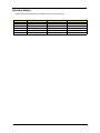
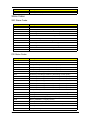
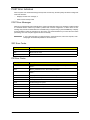
Revision History
Please refer to the table below for the updates made on this service guide.
ii
Date
Version
07-31-2012
First Draft
07-31-2012
V1.00
Chapter
Updates
Copyright
Copyright © 2012 by Acer Incorporated. All rights reserved. No part of this publication may be reproduced,
transmitted, transcribed, stored in a retrieval system, or translated into any language or computer language, in
any form or by any means, electronic, mechanical, magnetic, optical, chemical, manual or otherwise, without
the prior written permission of Acer Incorporated.
iii
Disclaimer
The information in this guide is subject to change without notice.
Acer Incorporated makes no representations or warranties, either expressed or implied, with respect to the
contents hereof and specifically disclaims any warranties of merchantability or fitness for any particular
purpose. Any Acer Incorporated software described in this manual is sold or licensed "as is". Should the
programs prove defective following their purchase, the buyer (and not Acer Incorporated, its distributor, or its
dealer) assumes the entire cost of all necessary servicing, repair, and any incidental or consequential
damages resulting from any defect in the software.
Acer is a registered trademark of Acer Corporation.
Other brand and product names are trademarks and/or registered trademarks of their respective holders.
HDMI, the HDMI logo, and High Definition Multimedia Interface are trademarks or registered trademarks of
HDMI Licensing, LLC in the United States and other countries.
iv
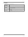
Conventions
The following conventions are used in this manual:
SCREEN
MESSAGES
Denotes actual messages that appear on screen.
NOTE
Gives additional information related to the current topic.
WARNING
Alerts you to any physical risk or system damage that might result from doing
or not doing specific actions.
CAUTION
Gives precautionary measures to avoid possible hardware or software
problems.
IMPORTANT
Reminds you to do specific actions relevant to the accomplishment of
procedures.
v
Service Guide Coverage
This Service Guide provides you with all technical information relating to the BASIC CONFIGURATION
decided for Acer's "global" product offering. To better fit local market requirements and enhance product
competitiveness, your regional office MAY have decided to extend the functionality of a machine (e.g. add-on
card, modem, or extra memory capability). These LOCALIZED FEATURES will NOT be covered in this generic
service guide. In such cases, please contact your regional offices or the responsible personnel/channel to
provide you with further technical details.
FRU Information
Please note WHEN ORDERING FRU PARTS, that you should check the most up-to-date information available
on your regional web or channel. If, for whatever reason, a part number change is made, it will not be noted in
the printed Service Guide. For ACER-AUTHORIZED SERVICE PROVIDERS, your Acer office may have a
DIFFERENT part number code to those given in the FRU list of this printed Service Guide. You MUST use the
list provided by your regional Acer office to order FRU parts for repair and service of customer machines.
vi
Table of Contents
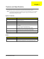
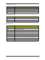
Features and Specifications............................................................................... 1
System Features . . . . . . . . . . . . . . . . . . . . . . . . . . . . . . . . . . . . . . . . . . . . . . . . . . . . . .1
Audio . . . . . . . . . . . . . . . . . . . . . . . . . . . . . . . . . . . . . . . . . . . . . . . . . . . . . . . . . . . . . . .1
I/O Ports and LED Indicators . . . . . . . . . . . . . . . . . . . . . . . . . . . . . . . . . . . . . . . . . . . . .2
Physical Specifications . . . . . . . . . . . . . . . . . . . . . . . . . . . . . . . . . . . . . . . . . . . . . . . . .2
Environmental Requirements . . . . . . . . . . . . . . . . . . . . . . . . . . . . . . . . . . . . . . . . . . . .2
System Tour . . . . . . . . . . . . . . . . . . . . . . . . . . . . . . . . . . . . . . . . . . . . . . . . . . . . . . . . .3
Front View
. . . . . . . . . . . . . . . . . . . . . . . . . . . . . . . . . . . . . . . . . . . . . . . . . . . .3
Rear Panel . . . . . . . . . . . . . . . . . . . . . . . . . . . . . . . . . . . . . . . . . . . . . . . . . . . . . .4
System Utilities.................................................................................................... 5
CMOS Setup Utility . . . . . . . . . . . . . . . . . . . . . . . . . . . . . . . . . . . . . . . . . . . . . . . . . . .5
Entering CMOS Setup . . . . . . . . . . . . . . . . . . . . . . . . . . . . . . . . . . . . . . . . . . . .5
Navigating Through the Setup Utility . . . . . . . . . . . . . . . . . . . . . . . . . . . . . . . . . . .6
Setup Utility Menus . . . . . . . . . . . . . . . . . . . . . . . . . . . . . . . . . . . . . . . . . . . . . . . .6
Info . . . . . . . . . . . . . . . . . . . . . . . . . . . . . . . . . . . . . . . . . . . . . . . . . . . . . . . . . . . . .7
Advanced . . . . . . . . . . . . . . . . . . . . . . . . . . . . . . . . . . . . . . . . . . . . . . . . . . . . . .8
Boot . . . . . . . . . . . . . . . . . . . . . . . . . . . . . . . . . . . . . . . . . . . . . . . . . . . . . . . . . . .9
Security . . . . . . . . . . . . . . . . . . . . . . . . . . . . . . . . . . . . . . . . . . . . . . . . . . . . . . .10
Exit . . . . . . . . . . . . . . . . . . . . . . . . . . . . . . . . . . . . . . . . . . . . . . . . . . . . . . . . . . .11
System Disassembly......................................................................................... 13
Disassembly Requirements . . . . . . . . . . . . . . . . . . . . . . . . . . . . . . . . . . . . . . . . . . . . .13
Pre-disassembly Procedure . . . . . . . . . . . . . . . . . . . . . . . . . . . . . . . . . . . . . . . . . . . .13
Disassembly Procedures . . . . . . . . . . . . . . . . . . . . . . . . . . . . . . . . . . . . . . . . . . . . . . .14
Removing the Computer Stand . . . . . . . . . . . . . . . . . . . . . . . . . . . . . . . . . . . . . .14
Removing the Side Panel . . . . . . . . . . . . . . . . . . . . . . . . . . . . . . . . . . . . . . . . . .15
Removing the Heatsink Assembly . . . . . . . . . . . . . . . . . . . . . . . . . . . . . . . . . . . .16
Removing the Speaker Module . . . . . . . . . . . . . . . . . . . . . . . . . . . . . . . . . . . . . .17
Removing the WLAN Module. . . . . . . . . . . . . . . . . . . . . . . . . . . . . . . . . . . . . . . .18
Removing the SSD Module . . . . . . . . . . . . . . . . . . . . . . . . . . . . . . . . . . . . . . . . .20
Removing the Mainboard . . . . . . . . . . . . . . . . . . . . . . . . . . . . . . . . . . . . . . . . . .21
Removing the Memory Modules . . . . . . . . . . . . . . . . . . . . . . . . . . . . . . . . . . . . .23
Removing the WLAN Antenna . . . . . . . . . . . . . . . . . . . . . . . . . . . . . . . . . . . . . . .24
Reassembly Procedures . . . . . . . . . . . . . . . . . . . . . . . . . . . . . . . . . . . . . . . . . . . . . . .26
Reinstalling the WLAN Antenna . . . . . . . . . . . . . . . . . . . . . . . . . . . . . . . . . . . . .26
Reinstalling the Memory Modules . . . . . . . . . . . . . . . . . . . . . . . . . . . . . . . . . . . .28
Reinstalling the Mainboard . . . . . . . . . . . . . . . . . . . . . . . . . . . . . . . . . . . . . . . . .29
Reinstalling the SSD Module . . . . . . . . . . . . . . . . . . . . . . . . . . . . . . . . . . . . . . . .31
Reinstalling the WLAN Module . . . . . . . . . . . . . . . . . . . . . . . . . . . . . . . . . . . . . .32
Reinstalling the Speaker Module . . . . . . . . . . . . . . . . . . . . . . . . . . . . . . . . . . . . .33
Reinstalling the Heatsink Assembly . . . . . . . . . . . . . . . . . . . . . . . . . . . . . . . . . . .34
Reinstalling the Side Panel . . . . . . . . . . . . . . . . . . . . . . . . . . . . . . . . . . . . . . . . .35
Removing the Computer Stand . . . . . . . . . . . . . . . . . . . . . . . . . . . . . . . . . . . . . .36
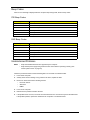
Troubleshooting ................................................................................................ 37
Hardware Diagnostic Procedure . . . . . . . . . . . . . . . . . . . . . . . . . . . . . . . . . . . . . . . . .37
System Check Procedures . . . . . . . . . . . . . . . . . . . . . . . . . . . . . . . . . . . . . . . . .37
Power System Check . . . . . . . . . . . . . . . . . . . . . . . . . . . . . . . . . . . . . . . . . . . . .37
System External Inspection . . . . . . . . . . . . . . . . . . . . . . . . . . . . . . . . . . . . . . . . 37
System Internal Inspection. . . . . . . . . . . . . . . . . . . . . . . . . . . . . . . . . . . . . . . . . 38
Checkpoints . . . . . . . . . . . . . . . . . . . . . . . . . . . . . . . . . . . . . . . . . . . . . . . . . . . . .38
Viewing BIOS Checkpoints . . . . . . . . . . . . . . . . . . . . . . . . . . . . . . . . . . . . . . . . .38
UEFI BIOS POST Code Checkpoints . . . . . . . . . . . . . . . . . . . . . . . . . . . . . . . . .38
vii
Table of Contents
Status Codes . . . . . . . . . . . . . . . . . . . . . . . . . . . . . . . . . . . . . . . . . . . . . . . . . . . .39
SEC Status Codes . . . . . . . . . . . . . . . . . . . . . . . . . . . . . . . . . . . . . . . . . . . . . . .39
PEI Status Codes . . . . . . . . . . . . . . . . . . . . . . . . . . . . . . . . . . . . . . . . . . . . . . . .39
DXE Status Codes . . . . . . . . . . . . . . . . . . . . . . . . . . . . . . . . . . . . . . . . . . . . . . .40
CPU Exception Status Codes . . . . . . . . . . . . . . . . . . . . . . . . . . . . . . . . . . . . . . .42
ASL Status Codes . . . . . . . . . . . . . . . . . . . . . . . . . . . . . . . . . . . . . . . . . . . . . . . .43
OEM-Reserved Status Codes . . . . . . . . . . . . . . . . . . . . . . . . . . . . . . . . . . . . . . 43
POST Error Indicators . . . . . . . . . . . . . . . . . . . . . . . . . . . . . . . . . . . . . . . . . . . . .44
POST Error Messages . . . . . . . . . . . . . . . . . . . . . . . . . . . . . . . . . . . . . . . . . . . .44
SEC Error Codes . . . . . . . . . . . . . . . . . . . . . . . . . . . . . . . . . . . . . . . . . . . . . . . .44
PEI Error Codes . . . . . . . . . . . . . . . . . . . . . . . . . . . . . . . . . . . . . . . . . . . . . . . . .44
DXE Error Codes . . . . . . . . . . . . . . . . . . . . . . . . . . . . . . . . . . . . . . . . . . . . . . . .45
Beep Codes . . . . . . . . . . . . . . . . . . . . . . . . . . . . . . . . . . . . . . . . . . . . . . . . . . . . .46
PEI Beep Codes . . . . . . . . . . . . . . . . . . . . . . . . . . . . . . . . . . . . . . . . . . . . . . . . .46
DXE Beep Codes . . . . . . . . . . . . . . . . . . . . . . . . . . . . . . . . . . . . . . . . . . . . . . . .46
Undetermined Problems . . . . . . . . . . . . . . . . . . . . . . . . . . . . . . . . . . . . . . . . . . .46
Clearing CMOS . . . . . . . . . . . . . . . . . . . . . . . . . . . . . . . . . . . . . . . . . . . . . . . . . . . . . .47
BIOS Recovery . . . . . . . . . . . . . . . . . . . . . . . . . . . . . . . . . . . . . . . . . . . . . . . . . . . . . .48
Creating the BIOS Crisis Recovery Disk . . . . . . . . . . . . . . . . . . . . . . . . . . . . . . .48
Performing a BIOS Recovery. . . . . . . . . . . . . . . . . . . . . . . . . . . . . . . . . . . . . . . .48
System Architecture.......................................................................................... 49
Block Diagram . . . . . . . . . . . . . . . . . . . . . . . . . . . . . . . . . . . . . . . . . . . . . . . . . . . . . . .49
Mainboard Layout (top) . . . . . . . . . . . . . . . . . . . . . . . . . . . . . . . . . . . . . . . . . . . . . . . .50
Mainboard Layout (bottom) . . . . . . . . . . . . . . . . . . . . . . . . . . . . . . . . . . . . . . . . . . . . .51
Jumper Setting . . . . . . . . . . . . . . . . . . . . . . . . . . . . . . . . . . . . . . . . . . . . . . . . . . .52
Field Replaceable Unit (FRU) List .................................................................... 53
Exploded Diagram . . . . . . . . . . . . . . . . . . . . . . . . . . . . . . . . . . . . . . . . . . . . . . . . . . .54
Veriton N2110G FRU List . . . . . . . . . . . . . . . . . . . . . . . . . . . . . . . . . . . . . . . . . . . . . .55
Technical Specifications................................................................................... 59
Processor . . . . . . . . . . . . . . . . . . . . . . . . . . . . . . . . . . . . . . . . . . . . . . . . . . . . . .59
System Board Major Chips . . . . . . . . . . . . . . . . . . . . . . . . . . . . . . . . . . . . . . . . .59
System Memory . . . . . . . . . . . . . . . . . . . . . . . . . . . . . . . . . . . . . . . . . . . . . . . . .60
System BIOS . . . . . . . . . . . . . . . . . . . . . . . . . . . . . . . . . . . . . . . . . . . . . . . . . . .60
Solid State Disk (SSD) Drive . . . . . . . . . . . . . . . . . . . . . . . . . . . . . . . . . . . . . . .60
Network Interface . . . . . . . . . . . . . . . . . . . . . . . . . . . . . . . . . . . . . . . . . . . . . . . .61
SATA Interface . . . . . . . . . . . . . . . . . . . . . . . . . . . . . . . . . . . . . . . . . . . . . . . . . .61
Audio Interface . . . . . . . . . . . . . . . . . . . . . . . . . . . . . . . . . . . . . . . . . . . . . . . . . .61
viii
Chapter 1
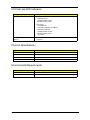
Features and Specifications
This chapter lists the features and specifications of the Veriton N2110G ThinClient computer.
NOTE
The items listed in this section are for reference only. The exact configuration of your TC depends
on the model purchased. Refer to the FRU list chapter on page 53 for a detailed list of models
supported by each hardware component.
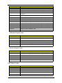
System Features
Component
Operating system support
Description
• Microsoft Windows Embedded Standard 7 SP1 (WES7)
• Devon - Detos v7.1.x
Processor
AMD Fusion APU G-T56N Dual core 1.65GHz
Chipset
AMD Hudson A55E FCH
Graphics controller
Integrated in the AMD Hudson A55E Chipset
Memory
• Two DIMM slots supporting 240-pin unbuffered DDR3 SDRAM
modules
• Data rate supported: 800/1066/1333 MT/s
• Maximum memory: 4 GB (using two 2 GB modules)
Connectivity
• Wired LAN: BCM57781B0KMLG QFN 10/100/1000
• WLAN option: 802.11 a/b/g/n wireless network adapter
Media Storage
One SATA 3.0 SSD slot (8G or 16G capacities)
Power supply
Universal AC Adapter, 100V~240V, 50-60Hz, 12V/4A output
Audio
Item
Description
Audio codec
Realtek ALC 269Q-VC2-GR
Audio jacks
• Front panel: Headphone/line-out and microphone/line-in jacks
• Rear panel: Headphone/line-out and microphone/line-in jacks
Veriton N2110G Service Guide
1
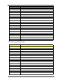
I/O Ports and LED Indicators
Component
Description
I/O ports
• Front panel
– USB ports (two)
– Headphone/line-out jack
– Microphone/line-in jack
• Rear panel
– Two HDMI port
– USB ports (2*USB2.0, 2*USB3.0)
– Ethernet jack (RJ45)
– Headphone/line-out jack
– Microphone/line-in jack
– DC-in jack
LED display and
buttons
• Power LED
• LAN LED
Physical Specifications
Aspect
Description
Chassis dimension (W × D × H)
40 mm (W) x 213 mm (D) x 259 mm (H)
System weight
1.407 Kg.
Mainboard form factor
microATX (µATX)
Mainboard dimensions (W × H)
175mm*205mm, 6 Layers
Environmental Requirements
2
Aspect
Description
Operating temperature
0 to 35 °C (32 to 95 °F)
Operating humidity
20% to 80% RH non-condensing
Veriton N2110G Service Guide
System Tour
The pictures and tables in this section illustrate the physical outlook of the computer.
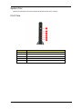
Front View
No.
Component
1
Power button/indicator
2
LAN LED indicator
3~4
USB 2.0 ports
5
Headphone/line-out jack
6
Microphone/line-in jack
Veriton N2110G Service Guide
3
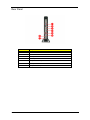
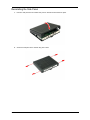
Rear Panel
4
No.
Component
1
USB 3.0 ports
2
LAN connector
3~4
HDMI ports
5
USB 2.0 ports
6
Headphone/line-out jack
7
DC-in jack
8
Microphone/line-in jack
Veriton N2110G Service Guide
Chapter 2
System Utilities
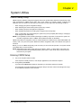
CMOS Setup Utility
CMOS setup is a hardware configuration program built into the system ROM, called the complementary metaloxide semiconductor (CMOS) Setup Utility. Since most systems are already properly configured and
optimized, there is no need to run this utility. You will need to run this utility under the following conditions.
•
When changing the system configuration settings
•
When redefining the communication ports to prevent any conflicts
•
When modifying the power management configuration
•
When changing the password or making other changes to the security setup
•
When a configuration error is detected by the system and you are prompted ("Run Setup" message) to
make changes to the CMOS setup
NOTE: If you repeatedly receive Run Setup messages, the battery may be bad. In this case, the system can
not retain configuration values in CMOS. Ask a qualified technician for assistance.
CMOS setup loads the configuration values in a battery-backed non-volatile memory called CMOS RAM. This
memory area is not part of the system RAM which allows configuration data to be retained when power is
turned off.
Before you run the CMOS Setup Utility, make sure that you have saved all open files. The system reboots
immediately after you close the Setup.
NOTE: CMOS Setup Utility will be simply referred to as “BIOS”, "Setup", or "Setup utility" in this guide. The
screenshots used in this guide display default system values. These values may not be the same as
those found in your system.
Entering CMOS Setup
1.
Turn on the computer and the monitor.
If the computer is already turned on, close all open applications, then restart the computer.
2.
During POST, press Delete.
If you fail to press Delete before POST is completed, you will need to restart the computer.
The Setup Main menu will be displayed showing the Setup’s menu bar. Use the left and right arrow keys
to move between selections on the menu bar.
Veriton N2110G Service Guide
5
Navigating Through the Setup Utility
Use the following keys to move around the Setup utility.
•
Left and Right arrow keys – Move between selections on the menu bar.
•
Up and Down arrow keys – Move the cursor to the field you want.
•
+ and - keys – Select a value for the currently selected field (only if it is user-configurable). Press these
keys repeatedly to display each possible entry, or the Enter key to choose from a pop-up menu.
NOTE: Grayed-out fields are not user-configurable.
• Enter key – Display a submenu screen.
NOTE: Availability of submenu screen is indicated by a (>).
•
Esc – If you press this key:
•
On one of the primary menu screens, the Exit menu displays.
•
On a submenu screen, the previous screen displays.
•
When you are making selections from a pop-up menu, closes the pop-up without making a selection.
•
F1 – Display the General Help panel.
•
F7 – Press to load user default values.
•
F8 – Press to save user default values.
•
F9 – Press to load optimized default system values.
•
F10 – Save changes made the Setup and close the utility.
Setup Utility Menus
The Setup Main menu includes the following main setup categories.
•
Info
•
Advanced
•
Boot
•
Security
•
Exit
In the descriptive table following each of the menu screenshots, settings in boldface are the default and
suggested settings.
6
Veriton N2110G Service Guide
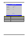
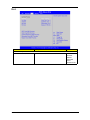
Info
The Info menu displays basic information about the system.
Parameter
Description
Product Name
Displays the product name (15 characters).
System Manufacturer
Displays the system manufacturer.
BIOS Version
Displays the current system BIOS version.
Memory Information
Total Memory
Total size of system memory installed on the system.
System Date
Set the date following the weekday-month-day-year format.
System Time (hh:mm:ss)
Set the system time following the hour-minute-second format.
Veriton N2110G Service Guide
7
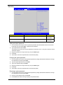
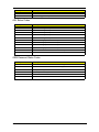
Advanced
8
Parameter
Description
Option
Onboard LAN PXE Boot
Enable or Disable Boot Option for Legacy Network
Devices.
Enabled
Disabled
Wake up on LAN
Turning this feature on will wake the system up when
the internal LAN device receives a Magic Packet in
Power-Off state.
Enabled
Disabled
EUP Function
Enable/Disable EUP Function.
Enabled
Disabled
AC Power Recovery
Specifies behaviour on AC power recovery after AC
power is disconnected and then plugged in.
On
Always Off
Resume on RTC
Enable/Disable RTC Function.
Note: The RTC function will not work in S5 when
EUP function is enabled.
Enabled
Disabled
Veriton N2110G Service Guide
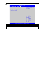
Boot
Parameter
Description
Option
Specifies the boot order from the available devices.
EFI
Hard Disk
CD/DVD
Removable
Device
Network Device
Set Boot Priority
1st/2nd/3rd/4th/5th Boot Device
Veriton N2110G Service Guide
9
Security
Parameter
Description
Option
Administrator Password
Indicates the status of the supervisor password.
Installed
Not Installed
User Password
Indicates the status of the User password.
Installed
Not Installed
Setting an system password
1.
Use the up/down arrow keys to select a password parameter (Set Administrator Password or Set User
Password) menu then press Enter. A password box will appear.
2.
Type a password then press Enter.
The password may consist up to twenty alphanumeric characters (A-Z, a-z, 0-9) with a minimum of three
characters required.
3.
Retype the password to verify the first entry then press Enter again.
4.
Press F10.
5.
Select Yes to save the new password and close the Setup Utility.
Changing the system password
1.
Use the up/down arrow keys to select password parameter (Change Administrator Password or Change
User Password) menu then press Enter.
2.
Type the original password then press Enter.
3.
Type a new password then press Enter.
4.
Retype the password to verify the first entry then press Enter again.
5.
Press F10.
6.
Select Yes to save the new password and close the Setup Utility.
Removing a system password
10
1.
Use the up/down arrow keys to select password parameter (Change Administrator Password or Change
User Password) menu then press Enter.
2.
Enter the current password then press Enter.
3.
Press Enter twice without entering anything in the password fields.
Veriton N2110G Service Guide
Exit
Parameter
Description
Save Changes and Reset
Reset the system after saving the changes of setup menu.
Discard Changes and Reset
Reset without saving.
Load Optimized Defaults
Restore/Load Defaults values for all the setup options.
Veriton N2110G Service Guide
11
12
Veriton N2110G Service Guide
Chapter 3
System Disassembly
This chapter contains step-by-step procedures on how to disassemble the ThinClient computer for
maintenance and troubleshooting.
Disassembly Requirements
To disassemble the computer, you need the following tools:
•
Wrist grounding strap and conductive mat for preventing electrostatic discharge
•
Philips screwdriver
NOTE: The screws for the different components vary in size. During the disassembly process, group the
screws with the corresponding components to avoid mismatch when putting back the components.
Pre-disassembly Procedure
Before proceeding with the disassembly procedure, perform the steps listed below:
1.
Turn off the system and all the peripherals connected to it.
2.
Unplug the power cord from the power outlets.
3.
Unplug the power cord from the system.
4.
Unplug all peripheral cables from the system.
5.
Place the system unit on a flat, stable surface.
Veriton N2110G Service Guide
13
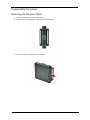
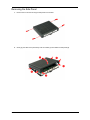
Disassembly Procedures
Removing the Computer Stand
14
1.
Place the computer on its side in a flat surface.
2.
Remove the screw securing the computer stand to the chassis.
3.
Pull the computer stand away from the chassis.
Veriton N2110G Service Guide
Removing the Side Panel
1.
Remove the four screws securing the side panel to the chassis.
2.
Gently pry the sides of the panel away from the chassis (1) then detach the side panel (2).
Veriton N2110G Service Guide
15
Removing the Heatsink Assembly
WARNING: The heatsink becomes very hot when the system is on. NEVER touch the heatsink with any metal
or with your bare hands.
16
1.
Loosen the six screws that secure the heatsink assembly to the mainboard.
2.
Lift the heatsink assembly off the mainboard.
Veriton N2110G Service Guide
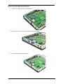
Removing the Speaker Module
1.
Disconnect the speaker cable from the mainboard.
2.
Remove the two screws securing the speaker module to the chassis.
3.
Lift the speaker module from the chassis.
Veriton N2110G Service Guide
17
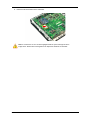
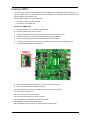
Removing the WLAN Module
1.
Disconnect the antenna cables from the WLAN card.
NOTE: For reference during machine reassembly, note which cable color corresponds to the main (white) and
auxiliary (black) connectors.
2.
18
Remove the screw securing the WLAN module to the mainboard.
Veriton N2110G Service Guide
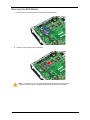
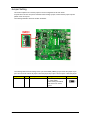
3.
Detach the WLAN module from the mainboard.
Note: A circuit board >10 cm2 has been highlighted with the yellow rectangle as above
image shows. Please follow local regulations for disposal of detached circuit boards.
Veriton N2110G Service Guide
19
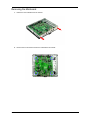
Removing the SSD Module
1.
Remove the two screws securing the SSD module to the mainboard.
2.
Detach the SSD module from the mainboard.
Note: A circuit board >10 cm2 has been highlighted with the yellow rectangle as above
image shows. Please follow local regulations for disposal of detached circuit boards.
20
Veriton N2110G Service Guide
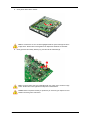
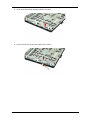
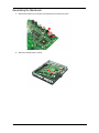
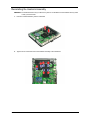
Removing the Mainboard
1.
Detach the rear IO bracket from the chassis.
2.
Remove the four screws that secure the mainboard to the chassis.
Veriton N2110G Service Guide
21
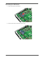
3.
Gently lift the board off the chassis.
Note: A circuit board >10 cm2 has been highlighted with the yellow rectangle as above
image shows. Please follow local regulations for disposal of detached circuit boards.
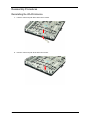
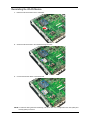
4.
Gently push the RTC battery sideways (1), then lift it off the mainboard (2).
Note: The RTC battery has been highlighted with the yellow circle as above image
shows. Please follow local regulations for disposal of used batteries.
Caution: Risk of explosion if battery is replaced by an incorrect type. Dispose of used
batteries according to the instructions.
22
Veriton N2110G Service Guide
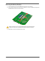
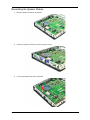
Removing the Memory Modules
1.
Turn the mainboard over to access the DIMM slots at the bottom of the mainboard.
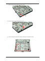
2.
Press outward the holding clips on both sides of the DIMM slot to release the DIMM (1), then gently pull
the DIMM upward to remove it from the chassis (2).
Note: A circuit board >10 cm2 has been highlighted with the yellow rectangle as above
image shows. Please follow local regulations for disposal of detached circuit boards.
3.
Repeat Step 2 to remove the remaining memory module.
Veriton N2110G Service Guide
23
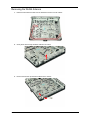
Removing the WLAN Antenna
24
1.
Detach the black antenna cable from the latches that secures it to the chassis.
2.
Gently lift the antenna clip with black cable from its socket.
3.
Remove the antenna clip with black cable from the chassis.
Veriton N2110G Service Guide
4.
Gently lift the antenna clip with white cable from its socket.
5.
Remove the antenna clip with white cable from the chassis.
Veriton N2110G Service Guide
25
Reassembly Procedures
Reinstalling the WLAN Antenna
26
1.
Insert the antenna clip with white cable into the chassis.
2.
Place the antenna clip with white cable into its socket.
Veriton N2110G Service Guide
1.
Insert the antenna clip with black cable into the chassis.
2.
Place the antenna clip with black cable into its socket.
3.
Secure the black antenna cable to the chassis by inserting it into the latches as shown.
Veriton N2110G Service Guide
27
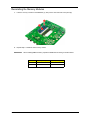
Reinstalling the Memory Modules
1.
Insert the memory module into the DIMM slot (1), then press it down until it latch into place (2).
2.
Repeat Step 1 to install the other memory module.
IMPORTANT
When installing DIMM modules, populate the DIMM slots according to the table below:
Size
DIMM1 (XMM1)
2G
4G
28
DIMM2 (XMM2)
2G
2G
2G
Veriton N2110G Service Guide
Reinstalling the Mainboard
1.
Slide the RTC battery into its socket in the mainboard until it latches into place.
2.
Slide the mainboard into the chassis.
Veriton N2110G Service Guide
29
30
3.
Secure the mainboard to the chassis using four screws.
4.
Align the latches of the rear IO bracket with the chassis (1), then gently push until the bracket latch into
place (2).
Veriton N2110G Service Guide
Reinstalling the SSD Module
1.
Insert the SSD module into the mainboard.
2.
Secure the SSD module to the mainboard using two screws.
Veriton N2110G Service Guide
31
Reinstalling the WLAN Module
1.
Detach the WLAN module from the mainboard.
2.
Secure the WLAN module to the mainboard using one screw.
3.
Connect the antenna cables to the WLAN card.
NOTE: For reference during machine reassembly, note which cable color corresponds to the main (white) and
auxiliary (black) connectors.
32
Veriton N2110G Service Guide
Reinstalling the Speaker Module
1.
Place the speaker module into the chassis.
2.
Secure the speaker module to the chassis using two screws.
3.
Connect the speaker cable to the mainboard.
Veriton N2110G Service Guide
33
Reinstalling the Heatsink Assembly
WARNING: The heatsink becomes very hot when the system is on. NEVER touch the heatsink with any metal
or with your bare hands.
34
1.
Place the heatsink assembly into the mainboard.
2.
Tighten the six screws that secure the heatsink assembly to the mainboard.
Veriton N2110G Service Guide
Reinstalling the Side Panel
1.
Place the side panel into the chassis then press on all sides until it latches into place.
2.
Secure the side panel to the chassis using four screws.
Veriton N2110G Service Guide
35
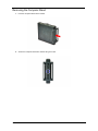
Removing the Computer Stand
36
1.
Push the computer stand into the chassis.
2.
Secure the computer stand to the chassis using one screw.
Veriton N2110G Service Guide
Chapter 4
Troubleshooting
This chapter lists the POST error indicators and BIOS beep codes, as well as general troubleshooting
instructions.
Hardware Diagnostic Procedure
1.
Obtain as much detail as possible about the symptoms of the system failure.
2.
Verify the symptoms by attempting to recreate the failure by running the diagnostic tests or repeating the
same operation.
3.
Refer to “Power System Check” procedure on the next section and the “Beep Codes” section on page 46
to determine which corrective action to take.
System Check Procedures
IMPORTANT: The diagnostic tests described in this chapter are only intended to test Acer products. Non-Acer
products, prototype cards, or modified options can give false errors and invalid system
responses.
Power System Check
If the system can be powered on, skip this section. Proceed to the “System Internal Inspection” procedure on
the next page.
If the system will not power on, do the following:
•
Check if the power cable is properly connected to the AC power jack and a functional AC power source.
•
Check if the voltage selector switch is set to the correct voltage setting.
System External Inspection
1.
Inspect the power and LED indicators on the front panel. Go to “Front View” section on page 3 for the
location and description of the LED behaviour.
2.
Make sure that there is no point of contact in the system that can cause a power short.
If the cause of the failure is still can not be determined, perform the “System Internal Inspection”
procedure described on the next page.
Veriton N2110G Service Guide
37
System Internal Inspection
1.
Turn off the power to the computer and all peripherals.
2.
Unplug the power cord from the computer.
3.
Unplug the network cable and all connected peripheral devices from the computer.
4.
Place the computer on a flat, steady surface.
5.
Remove the side panel as described in page 15.
6.
Verify that the SSD module and the RTC battery are properly seated.
7.
Remove the mainboard as described in page 21.
8.
Verify that memory module(s) are properly seated.
9.
Verify that all components are Acer-qualified and supported.
10. Reinstall the mainboard.
11. Reinstall the side panel.
12. Power on the system.
If the cause of the failure is still can not be determined, review the POST messages and BIOS
checkpoints during the system startup.
Checkpoints
A checkpoint is either a byte or word value output to I/O port 80h. The BIOS outputs checkpoints during
bootblock and Power-On Self Test (POST) to indicate the task the system is currently executing. Checkpoints
are very useful in aiding software developers or technicians in debugging problems that occur during the
pre-boot process.
Viewing BIOS Checkpoints
Viewing all checkpoints generated by the BIOS requires a checkpoint card, also referred to as a POST card or
POST diagnostic card. These are ISA or PCI add-in cards that show the value of I/O port 80h on a LED
display. Checkpoints may appear on the bottom right corner of the screen during POST. This display method is
limited, since it only displays checkpoints that occur after the video card has been activated.
NOTE: Please note that checkpoints may differ between different platforms based on system configuration.
Checkpoints may change due to vendor requirements, system chipset or option ROMs from add-in PCI
devices.
UEFI BIOS POST Code Checkpoints
The UEFI BIOS POST Code sets up the chipset, memory, and other components before system memory is
available. The following table describes the type of checkpoints that may occur during the boot block
initialization portion of the BIOS.
38
Checkpoint
Description
0x01 – 0x0F
SEC Status Codes & Errors
0x10 – 0x2F
PEI execution up to and including memory detection
0x30 – 0x4F
PEI execution after memory detection
0x50 – 0x5F
PEI errors
0x60 – 0xCF
DXE execution up to BDS
0xD0 – 0xDF
DXE errors
0xE0 – 0xE8
S3 Resume (PEI)
0xE9 – 0xEF
S3 Resume errors (PEI)
0xF0 – 0xF8
Recovery (PEI)
Veriton N2110G Service Guide
Checkpoint
Description
0xF9 – 0xFF
Recovery errors (PEI)
Status Codes
SEC Status Codes
Checkpoint
Description
0x1
Power on. Reset type detection (soft/hard).
0x2
AP initialization before microcode loading
0x3
North Bridge initialization before microcode loading
0x4
South Bridge initialization before microcode loading
0x5
OEM initialization before microcode loading
0x6
Microcode loading
0x7
AP initialization after microcode loading
0x8
North Bridge initialization after microcode loading
0x9
South Bridge initialization after microcode loading
0xA
OEM initialization after microcode loading
0xB
Cache initialization
PEI Status Codes
Checkpoint
Description
0x10
PEI Core is started
0x11
Pre-memory CPU initialization is started
0x12
CPU pre-memory initialization (CPU module specific)
0x13
CPU pre-memory initialization (CPU module specific)
0x14
CPU pre-memory initialization (CPU module specific)
0x15
Pre-memory North Bridge initialization is started
0x16
Pre-Memory North Bridge initialization (North Bridge module specific)
0x17
Pre-Memory North Bridge initialization (North Bridge module specific)
0x18
Pre-Memory North Bridge initialization (North Bridge module specific)
0x19
Pre-memory South Bridge initialization is started
0x1A
Pre-memory South Bridge initialization (South Bridge module specific)
0x1B
Pre-memory South Bridge initialization (South Bridge module specific)
0x1C
Pre-memory South Bridge initialization (South Bridge module specific)
0x1D – 0x2A
OEM pre-memory initialization codes
0x2B
Memory initialization. Serial Presence Detect (SPD) data reading
0x2C
Memory initialization. Memory presence detection
0x2D
Memory initialization. Programming memory timing information
0x2E
Memory initialization. Configuring memory
0x2F
Memory initialization (other).
0x30
Reserved for ASL (see ASL Status Codes section below)
0x31
Memory Installed
0x32
CPU post-memory initialization is started
Veriton N2110G Service Guide
39
Checkpoint
Description
0x33
CPU post-memory initialization. Cache initialization
0x34
CPU post-memory initialization. Application Processor(s) (AP) initialization
0x35
CPU post-memory initialization. Boot Strap Processor (BSP) selection
0x36
CPU post-memory
initialization
0x37
Post-Memory North Bridge initialization is started
0x38
Post-Memory North Bridge initialization (North Bridge module specific)
0x39
Post-Memory North Bridge initialization (North Bridge module specific)
0x3A
Post-Memory North Bridge initialization (North Bridge module specific)
0x3B
Post-Memory South Bridge initialization is started
0x3C
Post-Memory South Bridge initialization (South Bridge module specific)
0x3D
Post-Memory South Bridge initialization (South Bridge module specific)
0x3E
Post-Memory South Bridge initialization (South Bridge module specific)
0x3F-0x4E
OEM post memory initialization codes
0x4F
DXE IPL is started
initialization.
System
Management
Mode
(SMM)
S3 Resume Progress Codes
Checkpoint
Description
0xE0
S3 Resume is started (S3 Resume PPI is called by the DXE IPL)
0xE1
S3 Boot Script execution
0xE2
Video repost
0xE3
OS S3 wake vector call
0xE4-0xE7
Reserved for future AMI progress codes
0xE0
S3 Resume is started (S3 Resume PPI is called by the DXE IPL)
Recovery Progress Codes
Checkpoint
Description
0xF0
Recovery condition triggered by firmware (Auto recovery)
0xF1
Recovery condition triggered by user (Forced recovery)
0xF2
Recovery process started
0xF3
Recovery firmware image is found
0xF4
Recovery firmware image is loaded
0xF5-0xF7
Reserved for future AMI progress codes
DXE Status Codes
40
Checkpoint
Description
0x60
DXE Core is started
0x61
NVRAM initialization
0x62
Installation of the South Bridge Runtime Services
0x63
CPU DXE initialization is started
0x64
CPU DXE initialization (CPU module specific)
Veriton N2110G Service Guide
Checkpoint
Description
0x65
CPU DXE initialization (CPU module specific)
0x66
CPU DXE initialization (CPU module specific)
0x67
CPU DXE initialization (CPU module specific)
0x68
PCI host bridge initialization
0x69
North Bridge DXE initialization is started
0x6A
North Bridge DXE SMM initialization is started
0x6B
North Bridge DXE initialization (North Bridge module specific)
0x6C
North Bridge DXE initialization (North Bridge module specific)
0x6D
North Bridge DXE initialization (North Bridge module specific)
0x6E
North Bridge DXE initialization (North Bridge module specific)
0x6F
North Bridge DXE initialization (North Bridge module specific)
0x70
South Bridge DXE initialization is started
0x71
South Bridge DXE SMM initialization is started
0x72
South Bridge devices initialization
0x73
South Bridge DXE Initialization (South Bridge module specific)
0x74
South Bridge DXE Initialization (South Bridge module specific)
0x75
South Bridge DXE Initialization (South Bridge module specific)
0x76
South Bridge DXE Initialization (South Bridge module specific)
0x77
South Bridge DXE Initialization (South Bridge module specific)
0x78
ACPI module initialization
0x79
CSM initialization
0x7A – 0x7F
Reserved for future AMI DXE codes
0x80 – 0x8F
OEM DXE initialization codes
0x90
Boot Device Selection (BDS) phase is started
0x91
Driver connecting is started
0x92
PCI Bus initialization is started
0x93
PCI Bus Hot Plug Controller Initialization
0x94
PCI Bus Enumeration
0x95
PCI Bus Request Resources
0x96
PCI Bus Assign Resources
0x97
Console Output devices connect
0x98
Console input devices connect
0x99
Super IO Initialization
0x9A
USB initialization is started
0x9B
USB Reset
0x9C
USB Detect
0x9D
USB Enable
0x9E – 0x9F
Reserved for future AMI codes
0xA0
Reserved for ASL (see ASL Status Codes section below)
0xA1
IDE initialization is started
0xA2
IDE Reset
0xA3
IDE Detect
0xA4
IDE Enable
Veriton N2110G Service Guide
41
Checkpoint
Description
0xA5
SCSI initialization is started
0xA6
SCSI Reset
0xA7
SCSI Detect
0xA8
SCSI Enable
0xA9
Setup Verifying Password
0xAA
Reserved for ASL (see ASL Status Codes section below)
0xAB
Start of Setup
0xAC
Setup Input Wait
0xAD
Ready To Boot event
0xAE
Legacy Boot event
0xAF
Exit Boot Services event
0xB0
Runtime Set Virtual Address MAP Begin
0xB1
Runtime Set Virtual Address MAP End
0xB2
Legacy Option ROM Initialization
0xB3
System Reset
0xB4
USB hot plug
0xB5
PCI bus hot plug
0xB6
Clean-up of NVRAM
0xB7
Configuration Reset (reset of NVRAM settings)
0xB8 – 0xBF
Reserved for future AMI codes
0xC0 – 0xCF
OEM BDS initialization codes
CPU Exception Status Codes
42
Checkpoint
Description
0x00
Divide error
0x01
CPU Debug exception
0x02
Non Maskable hardware Interrupt occurred
0x03
INT 3 breakpoint
0x04
Overflow, INT 0 instruction
0x05
Bound Range Exceeded
0x06
Invalid Opcode (undefined opCode)
0x07
Device Not Available ( No Math Co-Processor)
0x08
Double Fault. Any instruction to the CPU that can Generate an NMI or INTR
0x09
Co-Processor Segment Overrun
0x0A
Invalid Task Switch Access
0x0B
Segment not present. Occurs after a load segment
0x0C
Stack Segment Fault. Relations to Stack operations
0x0D
General Protection fault. Any memory reference and other protection checks
0x0E
Page Fault.
0x0F
Reserved by Intel
0x10
Floating Point Error
0x11
Alignment Check
Veriton N2110G Service Guide
Checkpoint
Description
0x12
Machine Check
0x13
SIMD Floating point exception
ASL Status Codes
Checkpoint
Description
0x01
System is entering S1 sleep state
0x02
System is entering S2 sleep state
0x03
System is entering S3 sleep state
0x04
System is entering S4 sleep state
0x05
System is entering S5 sleep state
0x10
System is waking up from the S1 sleep state
0x20
System is waking up from the S2 sleep state
0x30
System is waking up from the S3 sleep state
0x40
System is waking up from the S4 sleep state
0xAC
System has transitioned into ACPI mode. Interrupt controller is in PIC mode.
0xAA
System has transitioned into ACPI mode. Interrupt controller is in APIC mode.
OEM-Reserved Status Codes
Checkpoint
Description
0x5
OEM SEC initialization before microcode loading
0xA
OEM SEC initialization after microcode loading
0x1D – 0x2A
OEM pre-memory initialization codes
0x3F – 0x4E
OEM PEI post memory initialization codes
0x80 – 0x8F
OEM DXE initialization codes
0xC0 – 0xCF
OEM BDS initialization codes
Veriton N2110G Service Guide
43
POST Error Indicators
When a system error is detected during POST (Power On Self Text), the Setup utility will switch to diagnostic
mode and will either:
•
Displays a POST error message, or
•
Emits a series of beep codes
POST Error Messages
POST error messages tell users what failure the system has detected. Some error messages could be related
to a hardware device. Others may indicate a problem with a device configuration. In some cases an error
message may include recommendations for troubleshooting or require that you press the Enter key to display
recommendations. Follow the instructions on the screen. It is recommended that you correct the error before
proceeding, even if the computer appears to boot successfully.
IMPORTANT
If your system fails after you make changes in the Setup menus, reboot the computer, enter
Setup again and load Setup defaults to correct the error.
SEC Error Codes
Checkpoint
Description
0xC – 0xD
Reserved for future AMI SEC error codes
0xE
Microcode not found
0xF
Microcode not loaded
PEI Error Codes
44
Checkpoint
Description
0x50
Memory initialization error. Invalid memory type or incompatible memory
speed
0x51
Memory initialization error. SPD reading has failed
0x52
Memory initialization error. Invalid memory size or memory modules do not
match.
0x53
Memory initialization error. No usable memory detected
0x54
Unspecified memory initialization error.
0x55
Memory not installed
0x56
Invalid CPU type or Speed
0x57
CPU mismatch
0x58
CPU self test failed or possible CPU cache error
0x59
CPU micro-code is not found or micro-code update is failed
0x5A
Internal CPU error
0x5B
reset PPI is not available
0x5C-0x5F
Reserved for future AMI error codes
Veriton N2110G Service Guide
S3 Resume Error Codes
Checkpoint
Description
0xE8
S3 Resume Failed in PEI
0xE9
S3 Resume PPI not Found
0xEA
S3 Resume Boot Script Error
0xEB
S3 OS Wake Error
0xEC-0xEF
Reserved for future AMI error codes
Recovery Error Codes
Checkpoint
Description
0xF8
Recovery PPI is not available
0xF9
Recovery capsule is not found
0xFA
Invalid recovery capsule
0xFB – 0xFF
Reserved for future AMI error codes
DXE Error Codes
Checkpoint
Description
0xD0
CPU initialization error
0xD1
North Bridge initialization error
0xD2
South Bridge initialization error
0xD3
Some of the Architectural Protocols are not available
0xD4
PCI resource allocation error. Out of Resources
0xD5
No Space for Legacy Option ROM
0xD6
No Console Output Devices are found
0xD7
No Console Input Devices are found
0xD8
Invalid password
0xD9
Error loading Boot Option (LoadImage returned error)
0xDA
Boot Option is failed (StartImage returned error)
0xDB
Flash update is failed
0xDC
Reset protocol is not available
Veriton N2110G Service Guide
45
Beep Codes
When no error message is displayed but the computer stops during POST, listen for beep codes.
PEI Beep Codes
No. of Beeps
Description
4
Some of the Architectural Protocols are not available
5
No Console Output Devices are found
5
No Console Input Devices are found
1
Invalid password
6
Flash update is failed
7
Reset protocol is not available
DXE Beep Codes
No. of Beeps
Description
4
Some of the Architectural Protocols are not available
5
No Console Output Devices are found
5
No Console Input Devices are found
1
Invalid password
6
Flash update is failed
7
Reset protocol is not available
Undetermined Problems
NOTE
• Verify that all attached devices are supported by the computer.
• Verify that the power supply being used at the time of the failure is operating correctly. (See
“Power System Check” on page 37)
Follow the procedures below to isolate the failing FRU. Do not isolate non-defective FRU.
1.
Power off the computer.
2.
Visually check them for damage. If any problems are found, replace the FRU.
3.
Remove or disconnect all of the following devices:
•
Non-Acer devices
•
SSD drive
•
DIMM
4.
Power on the computer.
5.
Determine if the problem has been resolved.
6.
If the problem does not recur, reconnect the removed devices one at a time until you find the failed FRU.
If the problem persists, replace the mainboard. Do not replace a non-defective FRU.
46
Veriton N2110G Service Guide
Clearing CMOS
You may need to clear the Setup configuration values (CMOS) if the configuration has been corrupted, or if
incorrect settings made in the Setup Utility caused error messages to be unreadable. This procedure will clear
the BIOS supervisor password as well.
Use the CMOS1 jumper to clear the CMOS data.
•
1-2 position: Normal operation (default)
•
2-3 position: Clear CMOS data
To clear the CMOS data:
1.
Turn off the power to the computer and all peripherals.
2.
Unplug the power cord from the computer.
3.
Unplug the network cable and all connected peripheral devices from the computer.
4.
Place the computer on a flat, steady surface with side panel facing upward.
5.
Remove the side panel by following the procedures described on page 15.
6.
If necessary, remove any other components or cables that prevent access to the CMOS1 jumper.
7.
Locate the CMOS1 jumper on the mainboard.
8.
Remove the jumper block and set it over the 2-3 pins for 20 to 30 seconds.
9.
Return the jumper block to its default 1-2 position.
10. Reinstall any other components or cables that have previously been removed.
11. Reinstall the computer cover.
12. Connect the power cord to the system.
13. Press the power button to turn on the computer.
14. During POST, press Delete to access the Setup Utility.
15. Press F9 to load the system default values.
16. Press F10 to save the changes you made and close the Setup Utility.
Veriton N2110G Service Guide
47
BIOS Recovery
When you boot up the computer and you hear one long beep, followed by a shorter one, the system BIOS is
damaged. This maybe cause by an interruption during a BIOS flash procedure (e.g. a power outage) or a
corrupted BIOS code, which will cause the system to go into an unbootable state.You need to access and
execute the boot block program to reboot the computer and recover the regular BIOS code.
Note the following when restoring the BIOS settings:
•
Make sure the computer is connected to a UPS unit during the BIOS recovery process.
•
The BIOS crisis recovery disk should be prepared in a computer running the Windows XP or Windows
Vista OS. A USB floppy, optical, or hard drive can be used.
Creating the BIOS Crisis Recovery Disk
1.
Set up a computer running the Windows XP or Windows Vista operating system and connect the BIOS
recovery media.
2.
Copy the target BIOS ROM file to the BIOS recovery media and rename it as “amiboot.rom”.
3.
Eject the BIOS recovery media from the computer.
Performing a BIOS Recovery
NOTE
This procedure is only applicable when the boot block section is still valid.
1.
Shut down the system with failed BIOS.
2.
Put the BIOS.ROM (like P01-A0) to a bootable USB storage.
3.
Rename BIOS rom file (it may exist at \ROM\xxx.ROM) to AMIBOOT.ROM
4.
Plug the USB storage to the system.
5.
Press the power button to turn on the system.
The system will now execute the BIOS recovery process. You will hear a long beep followed by a short beep.
6.
Select Proceed with flash update start recovery.
7.
Wait for the program to finish with the recovery.
8.
Flash update completed.
9.
Press any key to reboot system.
10. The BIOS recovery is now completed.
48
Veriton N2110G Service Guide
Chapter 5
System Architecture
This chapter shows the block diagram and board layout of the Veriton N2110G computer.
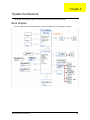
Block Diagram
The core subsystems of the Veriton N2110G computer are depicted in the following block diagram:
Veriton N2110G Service Guide
49
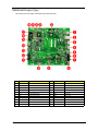
Mainboard Layout (top)
This section shows the major mainboard components (top view).
50
No.
Label
Description
No.
Label
Description
1
J82
Rear USB 3.0 port
12
J75
Front headphone jack
2
J9
LAN connector
13
SKT4
Front USB 2.0 port
3
J64
HDMI port
14
SKT5
Front USB 2.0 port
4
J65
HDMI port
15
CR15
LAN LED
5
J81
Rear USB 2.0 port
16
XBT1
RTC Battery slot
6
J77
Rear headphone jack
17
CR14
Power LED
7
J76
Rear microphone jack
18
SW1
Power button
8
J103
DC-in jack
19
U19
SPI ROM
9
J105
WLAN slot
20
U16
SIO
10
P62
SSD slot
21
U4
Hudson E1-SB
11
J72
Front microphone jack
22
U1
T56N-APU
Veriton N2110G Service Guide
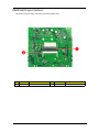
Mainboard Layout (bottom)
This section shows the major mainboard components (bottom view).
No.
Label
Description
No.
Label
Description
1
XMM2
DIMM Slot 2
2
XMM1
DIMM Slot 1
Veriton N2110G Service Guide
51
Jumper Setting
This section explains how to set the jumper for correct configuration of the main board.
Jumpers with more than one pin are numbered. When setting a jumper, ensure that the jumper caps are
placed on the correct pins.
The following illustration shows the location of CMOS1:
The following table shows the settings of the 3-pin Clear CMOS (CMOS1) jumper. Place the jumper cap on
pins 1 and 2 to close or short the jumper. Place the jumper cap on pins 2 and 3 to open or clear the jumper.
52
Jumper
Type
Description
Setting (default)
CMOS1
3-pin
Clear CMOS
1-2: Normal (default)
2-3: Clear CMOS
Before clearing the CMOS,
make sure to turn off the
system.
Veriton N2110G Service Guide
Chapter 6
Field Replaceable Unit (FRU) List
This chapter gives you the FRU (Field Replaceable Unit) listing of the Veriton N2110G ThinClient computer
global configurations. Refer to this list when ordering for repair parts or for RMA (Return Merchandise
Authorization).
IMPORTANT
NOTE
When ordering FRU parts, check the most up-to-date information available on your regional
web or channel. For whatever reasons a part number is changed, it will NOT be noted on the
printed Service Guide. For Acer authorized service providers, your Acer office may have a
different part number code from those given in the FRU list of this printed Service Guide. You
MUST use the local FRU list provided by your regional Acer office to order FRU parts for
service.
Follow the local government regulations, or the rules set by your regional office on how to return or
dispose of defective parts.
Veriton N2110G Service Guide
53
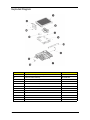
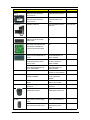
Exploded Diagram
54
No.
Description
Part No.
1
Top cover assembly (Side Panel)
60.3HH02.001
2
Thermal module assembly
60.3HH09.001
3
Screw M3 X 6L
86.00B75.240
4
Mainboard
81.3HH10.013G
5
Rear IO bracket assembly
60.3HH06.001
6
Auxiliary antenna
25.90ADA.001
7
Bottom cover assembly
60.3HH05.001
8
Computer stand/base
60.3HH03.001
9
Screw M3 X L10.0
86.5A324.100
10
SSD module
56.02Z26.001
11
Speaker module
23.40A5R.001
12
Main antenna
25.90AD9.001
Veriton N2110G Service Guide
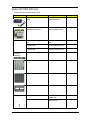
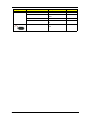
Veriton N2110G FRU List
ACER_VN2110G_TC6(NO:91.3HH01.001G)
Category
Part Name
Description
Acer Part No.
ADAPTER
ADAPTER 48W 12V/4A AU799IN
ADP 48W 12V/4A AU799IN PA40NX-TC6
25.VFTD1.001
BOARDS
WLAN 802.11ABGN +BT4.0
COMBO CARD AR9462
WLAN 802.11ABGN
+BT4.0 COMBO AR9462
DA.VFT11.001
CABLES
POWER CORD 110V 3PIN UL
USA
POWER CORD 110V UL
USA
27.01518.0I1
DP TO VGA DONGLE
CONNECTOR
ICT-LANTO DP TO VGA
DONGLE LA00DP002-1N
DP.VFT11.001
DP TO DVI DONGLE
CONNECTOR
ICT-LANTO DP TO DVI
DONGLE LA00DP001-1N
DP.VFT11.002
REAR IO BRACKET
ASSY-BRKT-REAR-IO-TC6
33.VFTD1.001
BOTTOM COVER
ASSY-CVR-BOTTOM-TC6
60.VFTD1.001
TOP COVER
ASSY-CVR-TOP-TC6
60.VFTD1.002
STAND BASE
ASSY-STAND-BASE-TC6
60.VFTD1.003
WLAN ANTENNA MAIN WHITE
ANT WLAN MAIN WHITE
95MM ACON
50.VFTD1.003
WLAN ANTENNA AUX BLACK
ANT WLAN AUX BLACK
400MM ACON
50.VFTD1.004
CASE/COVER/
BRACKET
ASSEMBLY
COMM. MODULE
Veriton N2110G Service Guide
55
Category
Part Name
Description
Acer Part No.
HDD/HARD DISK
DRIVE
SSD-M 16GB SANDISK
SDSA5AK-016G SATA MLC
FW:V.10.02.00
SSD-M 16GB SANDISK
SDSA5AK-016G HALF-SLI
KN.16G0D.001
SSD-M 8GB SANDISK
SDSA5AK-008G SATA MLC
FW:V.10.02.00
SSD-M 8GB SANDISK
SDSA5AK-008G HALFSLIM
KN.8GB0D.00
1
HEATSINK
THERMAL MODULE
ASSY THERMAL MODULE
T56N TC6
60.VFTD1.004
KEYBOARD
KEYBOARD PRIMAX PR1101U
USB BLACK US WITH NEW
ACER LOGO
KB PR1101U USB BLACK
US
KB.USB0P.259
MAINBOARD
MAINBOARD KIT WMKT56N
AMD T56N A55E RADEON HD
6320 BCM57781B0KMLG LF
EUP2013 W/APU W/O DIMM
PA55EV-TC6 AMD T56N -1
MB
DB.VFT11.001
MEMORY
SODIMM 2GB DDRIII 1333
NANYA NT2GC64B88G0NS-CG
LF+HF
SODIMM 2G
NT2GC64B88G0NS-CG
DDR3 1333MHZ
KN.2GB03.025
SODIMM 2GB DDRIII 1333MHZ
SAMSUNG M471B5773DH0CH9 LF 256*8
SODIMM 2G
M471B5773DH0-CH9
DDR3 1333MHZ
KN.2GB0B.030
SODIMM 2GB DDRIII 1333
HYNIX HMT325S6CFR8C-H9
LF+HF 256X8 38NM
SODIMM 2G
HMT325S6CFR8C-H9
DDR3 1333MHZ
KN.2GB0G.031
THERMAL PAD
T-PAD SODIMM K1.8
20X55X1.5T PLYM EAPUS
47.VFTD1.001
EMI-GASKET-L35-W12H12ANGUS19-COMBO
EMI-GASKET-L35W12H12-ANGUS19COMBO
47.VFTD1.002
EMI GASKET 10W*10L*0.5T
SOMA
EMI GASKET
10W*10L*0.5T SOMA
47.VFTD1.003
EMI_XPANSION_GASKET
W5*L62*T1
EMI_XPANSION_GASKET
W5*L62*T1
47.VFTD1.004
ASSEMBLY RUBBER
HORIZONTAL FOOT*4
ASSY-RUBBERHORIZONTAL-FOOT-TC6
47.VFTD1.005
LOGITECH OPTICAL MOUSE
USB M-U0027-O WITH ACER
LOGO
MOUSE OPTICAL USB MU0027-O WITH ACER LO
MS.11200.106
PRIMAX OPTICAL MOUSE USB
MOFGUO WITH ACER LOGO
MOUSE OPTICAL MOUSE
USB MOFGUO WITH
ACER
MS.11200.107
MISC.
POINTING
DEVICE
56
Veriton N2110G Service Guide
Category
Part Name
Description
Acer Part No.
SCREWS
SCREW M2 CAP L4 NI
SCRW M2 CAP L4 NI
86.NBY01.003
SCREW
SCRW M3 CAP D7 6L NI
H801
86.U5P01.001
SCREW MACH M1.4 L8 NI
SCRW MACH M1.4 L8 NI
86.VFTD1.001
SCREW BI M3 L10.0 BLACK ZN
SCRW BI M3 L10.0 BLACK
ZN
86.VFTD1.002
SPEAKER
SPEAKER L04020A-176-2
TC6
23.VFTD1.001
SPEAKER
Veriton N2110G Service Guide
57
58
Veriton N2110G Service Guide
Appendix A
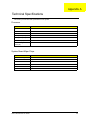
Technical Specifications
This section provides technical specifications for the system.
Processor
Item
Specification
Type
AMD Fusion
Processor Number
G-T56N
Number of Cores
Dual
Clock Speed (GHz)
1.65
Turbo Speed (GHz)
N/A
Cache Size (MB)
1
Thermal Design
Power (W)
18
System Board Major Chips
Item
Specification
System Core Logic
AMD Hudson A55E FCH
Video Controller
Integrated Radeon HD 6320
LAN Controller
BCM57781B0KMLG QFN
Audio Controller
Realtek ALC 269Q-VC2-GR Audio Codec
USB Controller
Integrated in the AMD Hudson A55E FCH
Input Devices Controller
Super I/O IT8728F/FX
Veriton N2110G Service Guide
59
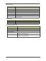
System Memory
Item
Specification
Controller
Integrated in the AMD Hudson A55E FCH
Number of DIMM slot
2
Maximum memory
4 GB (using two 2 GB modules)
Data rate
1066/1333/1866 MT/s
Supported capacities
2 GB
DIMM type
204-pin DDR3 SO-DIMM
Supported brands
Nanya, Hynix, Samsung
Population rule
You can install memory modules in any combination as long as they match the
above specifications.
System BIOS
Item
Specification
BIOS Vendor
American Megatrends Inc.
BIOS Version
P01-A0
Solid State Disk (SSD) Drive
Item
Specification
Controller
Integrated in the AMD Hudson A55E FCH
Number of SSD slots
1
Interface
SATA 3.0
Supported capacities
8 GB
• SANDISK – SDSA5AK-008G
• APACER – APS1845008G-ACM
16 GB
• SANDISK – SDSA5AK-016G
• APACER – APS1845016G-ACM
60
Veriton N2110G Service Guide
Network Interface
Item
Specification
LAN Controller
BCM57781B0KMLG QFN
Supports LAN Protocol
10/100/1000 Mbps
LAN Connector Type
RJ45
SATA Interface
Item
Specification
SATA Controller
Embedded SATA controller
Connectors
One SATA 3.0 interface
Audio Interface
Item
Specification
Audio Controller
Realtek ALC 269Q-VC2-GR Audio Codec
Connectors
Four audio jacks (2 in front and 2 at the back)
Veriton N2110G Service Guide
61
62
Veriton N2110G Service Guide
Index
A
D
audio
headphone jack 3, 4
microphone jack, rear 4
B
Basic Input/Output System, see BIOS 5
disassembly procedures
HDD-ODD bracket 18, 32
memory 23, 28
side panel 29
E
environmental requirements 2
beep codes 46
exploded view 54
BIOS 60
checkpoints 38
clear CMOS 47
CMOS RAM 5
configure 5
crisis recovery disk 48
overview 5
recovery 48
vendor 60
Version 60
BIOS menus
Advanced 8
Boot Options 11
Exit 11
Integrated Peripherals
external modules disassembly
font bezel 15, 35
F
Field Replaceable Unit, see FRU list 53
FRU list
components list 55
exploded view 54
part number updates 53
H
hardware
exploded view 54
FRU list 53
troubleshooting 37
HDD-ODD bracket
remove 18, 32
USB Device Setting 9
Miscellaneous 9
PC Health Status 10
Power Management Setup 9
BIOS Setup
enter Setup 5
block diagram 49
boot block
checkpoints 38, 39
execute 48
button
optical drive eject 3
headphone jack 3, 4
humidity 2
I
I/O ports 2
J
jack
microphone-in 3, 4
M
main board placement 50, 51
C
main unit disassembly
heat sink 16, 34
mainboard 21, 26
power supply 24
processor 17, 33
mainboard
component identification 50, 51
specifications 2
card reader
multi-in-1 3
checkpoints
boot block 38, 39
overview 38
POST 39, 40, 42, 43
CMOS clear 47
major chipsets 59
CMOS RAM 5
connectivity
options 1
connector
LAN 4
PS/2 mouse 4
cover
optical drive 3
memory
remove 23, 28
microphone jack
rear 4
O
operating system 1
OS support 1
63
P
rear 4
PC Card 61
PCMCIA 61
PhoenixBIOS Setup Utility, see BIOS Setup 5
POST, see Power-On Self-Test 39, 40, 42, 43
power
button/indicator 3
specifications 1
Power-On Self-Test
beep codes 46
checkpoints 39, 40, 42, 43
error messages 44
processor 59
R
Return Merchandise Authorization 53
RMA, see Return Merchandise Authorization 53
S
side panel
remove 29
software specifications
operating system 1
system architecture 49
system dimensions 2
system disassembly 13
preinstallation instructions 13
requirements 13
system features
SATA controller 1
system memory 60
system tour
rear panel 4
system utilities 5
system views
front view 3
system weight 2
T
technical specifications 59
temperature
operating 2
troubleshooting
BIOS checkpoints 38
BIOS recovery 48
clearing CMOS 47
hardware diagnostic procedure 37
POST error indicators 44
U
undetermined problems 46
USB ports
front 3, 4
64
V
video
controller 1
65