1
Model 1830, 1850 & 1850W Dehumidifier
Installation Instructions
Safety Instructions
WARNING
1. 120 Volts may cause serious injury from electric shock. Disconnect electrical power before starting installation or servicing.
Leave power disconnected until installation/service is completed.
2. Sharp edges may cause serious injury from cuts. Use care when cutting plenum openings and handling duct work.
3. Dropping may cause personal injury or equipment damage. Handle with care and follow installation instructions.
CAUTION
1. Read all instructions before beginning installation.
2. Improper installation may cause property damage or injury. Installation, service, and maintenance must be performed by a
qualified service technician.
3. Do not use in pool applications. Pool chemicals can damage the dehumidifier.
4. Do not use solvents or cleaners on or near the circuit board. Chemicals can damage circuit board components.
5. Wait 24 hours before running the unit if it was not shipped or stored in the upright position
6. Do not use dehumidification to prevent window condensation in the winter. To address window condensation, use ventilation
to lower indoor humidity in the winter.
READ AND SAVE THESE INSTRUCTIONS
1
Table of Contents
Safety Instructions . . . . . . . . . . . . . . . . . . . . . . . . . . . . . . . . . . . . . . . . . . . . . . . . . . . . . . . . . . . . . . . . . . . . . . . . . . . . . . . . . . . . . . . . . . . . . . . . . . . . . 1
Specifications . . . . . . . . . . . . . . . . . . . . . . . . . . . . . . . . . . . . . . . . . . . . . . . . . . . . . . . . . . . . . . . . . . . . . . . . . . . . . . . . . . . . . . . . . . . . . . . . . . . . . . . . . 3
Set Up Dehumidifier for Installation . . . . . . . . . . . . . . . . . . . . . . . . . . . . . . . . . . . . . . . . . . . . . . . . . . . . . . . . . . . . . . . . . . . . . . . . . . . . . . . . . . . . . . 3
Duct Collars . . . . . . . . . . . . . . . . . . . . . . . . . . . . . . . . . . . . . . . . . . . . . . . . . . . . . . . . . . . . . . . . . . . . . . . . . . . . . . . . . . . . . . . . . . . . . . . . . . . . . . . . . . 4
Control Location . . . . . . . . . . . . . . . . . . . . . . . . . . . . . . . . . . . . . . . . . . . . . . . . . . . . . . . . . . . . . . . . . . . . . . . . . . . . . . . . . . . . . . . . . . . . . . . . . . . . . . . 5
Hard Wiring . . . . . . . . . . . . . . . . . . . . . . . . . . . . . . . . . . . . . . . . . . . . . . . . . . . . . . . . . . . . . . . . . . . . . . . . . . . . . . . . . . . . . . . . . . . . . . . . . . . . . . . . . . . 6
Electrical Specifications for Hard Wiring . . . . . . . . . . . . . . . . . . . . . . . . . . . . . . . . . . . . . . . . . . . . . . . . . . . . . . . . . . . . . . . . . . . . . . . . . . . . . . . . . . . 6
Wiring Instructions . . . . . . . . . . . . . . . . . . . . . . . . . . . . . . . . . . . . . . . . . . . . . . . . . . . . . . . . . . . . . . . . . . . . . . . . . . . . . . . . . . . . . . . . . . . . . . . . . . . . . 7
Location Considerations . . . . . . . . . . . . . . . . . . . . . . . . . . . . . . . . . . . . . . . . . . . . . . . . . . . . . . . . . . . . . . . . . . . . . . . . . . . . . . . . . . . . . . . . . . . . . . . . 8
Drain Installation . . . . . . . . . . . . . . . . . . . . . . . . . . . . . . . . . . . . . . . . . . . . . . . . . . . . . . . . . . . . . . . . . . . . . . . . . . . . . . . . . . . . . . . . . . . . . . . . . . . . . . 9
Leveling . . . . . . . . . . . . . . . . . . . . . . . . . . . . . . . . . . . . . . . . . . . . . . . . . . . . . . . . . . . . . . . . . . . . . . . . . . . . . . . . . . . . . . . . . . . . . . . . . . . . . . . . . . . . . . 9
Condensate Pan, Condensate Pump and Float Switch . . . . . . . . . . . . . . . . . . . . . . . . . . . . . . . . . . . . . . . . . . . . . . . . . . . . . . . . . . . . . . . . . . . . . . . . . 9
Ducting to HVAC System – Basement and Attic Installations . . . . . . . . . . . . . . . . . . . . . . . . . . . . . . . . . . . . . . . . . . . . . . . . . . . . . . . . . . . . . . 10
Ducting to HVAC System – Closet Installations . . . . . . . . . . . . . . . . . . . . . . . . . . . . . . . . . . . . . . . . . . . . . . . . . . . . . . . . . . . . . . . . . . . . . . . . . . . 11
Ducting for Stand Alone Installations or Non-Ducted Installations . . . . . . . . . . . . . . . . . . . . . . . . . . . . . . . . . . . . . . . . . . . . . . . . . . . . . . . . . 11
Ducting for Two Zone Installations . . . . . . . . . . . . . . . . . . . . . . . . . . . . . . . . . . . . . . . . . . . . . . . . . . . . . . . . . . . . . . . . . . . . . . . . . . . . . . . . . . . . . . 12
Model 76 – External Control or Crawl Space/Sealed Attic Control and Wiring . . . . . . . . . . . . . . . . . . . . . . . . . . . . . . . . . . . . . . . . . . . . . . 13
Wiring the Dehumidifier to the HVAC System and Zone Dampers . . . . . . . . . . . . . . . . . . . . . . . . . . . . . . . . . . . . . . . . . . . . . . . . . . . . . . . . . . 14
System Set Up and Checkout . . . . . . . . . . . . . . . . . . . . . . . . . . . . . . . . . . . . . . . . . . . . . . . . . . . . . . . . . . . . . . . . . . . . . . . . . . . . . . . . . . . . . . . . . . . 15
Installer Test Mode . . . . . . . . . . . . . . . . . . . . . . . . . . . . . . . . . . . . . . . . . . . . . . . . . . . . . . . . . . . . . . . . . . . . . . . . . . . . . . . . . . . . . . . . . . . . . . . . . . . 17
Start Up and Sequence of Operation . . . . . . . . . . . . . . . . . . . . . . . . . . . . . . . . . . . . . . . . . . . . . . . . . . . . . . . . . . . . . . . . . . . . . . . . . . . . . . . . . . . .
Single Zone Whole House or Stand Alone Using the Dehumidifier Control . . . . . . . . . . . . . . . . . . . . . . . . . . . . . . . . . . . . . . . . . . . . . . . . . . . . . . .
Single Zone Whole House or Stand Alone Using Model 76 External Control . . . . . . . . . . . . . . . . . . . . . . . . . . . . . . . . . . . . . . . . . . . . . . . . . . . . . .
Crawl Space (Remote) Control Using Model 76 . . . . . . . . . . . . . . . . . . . . . . . . . . . . . . . . . . . . . . . . . . . . . . . . . . . . . . . . . . . . . . . . . . . . . . . . . . . . .
Two Zone – Primary and Secondary . . . . . . . . . . . . . . . . . . . . . . . . . . . . . . . . . . . . . . . . . . . . . . . . . . . . . . . . . . . . . . . . . . . . . . . . . . . . . . . . . . . . . .
18
18
18
18
18
Ventilation . . . . . . . . . . . . . . . . . . . . . . . . . . . . . . . . . . . . . . . . . . . . . . . . . . . . . . . . . . . . . . . . . . . . . . . . . . . . . . . . . . . . . . . . . . . . . . . . . . . . . . . . . . .
Installation and Wiring . . . . . . . . . . . . . . . . . . . . . . . . . . . . . . . . . . . . . . . . . . . . . . . . . . . . . . . . . . . . . . . . . . . . . . . . . . . . . . . . . . . . . . . . . . . . . . . . .
Vent Auto & Vent-Timed . . . . . . . . . . . . . . . . . . . . . . . . . . . . . . . . . . . . . . . . . . . . . . . . . . . . . . . . . . . . . . . . . . . . . . . . . . . . . . . . . . . . . . . . . . . . . . .
Outdoor Temperature Sensor Installation . . . . . . . . . . . . . . . . . . . . . . . . . . . . . . . . . . . . . . . . . . . . . . . . . . . . . . . . . . . . . . . . . . . . . . . . . . . . . . . . . .
Determine Ventilation Requirements . . . . . . . . . . . . . . . . . . . . . . . . . . . . . . . . . . . . . . . . . . . . . . . . . . . . . . . . . . . . . . . . . . . . . . . . . . . . . . . . . . . . .
Installer Settings . . . . . . . . . . . . . . . . . . . . . . . . . . . . . . . . . . . . . . . . . . . . . . . . . . . . . . . . . . . . . . . . . . . . . . . . . . . . . . . . . . . . . . . . . . . . . . . . . . . . .
Sequence of Operation . . . . . . . . . . . . . . . . . . . . . . . . . . . . . . . . . . . . . . . . . . . . . . . . . . . . . . . . . . . . . . . . . . . . . . . . . . . . . . . . . . . . . . . . . . . . . . . . .
19
19
20
20
21
22
23
Troubleshooting . . . . . . . . . . . . . . . . . . . . . . . . . . . . . . . . . . . . . . . . . . . . . . . . . . . . . . . . . . . . . . . . . . . . . . . . . . . . . . . . . . . . . . . . . . . . . . . . . . . . . . . 24
Table 4 – Diagnostic Codes . . . . . . . . . . . . . . . . . . . . . . . . . . . . . . . . . . . . . . . . . . . . . . . . . . . . . . . . . . . . . . . . . . . . . . . . . . . . . . . . . . . . . . . . . . . . . 24
Table 5 – Troubleshooting Guide . . . . . . . . . . . . . . . . . . . . . . . . . . . . . . . . . . . . . . . . . . . . . . . . . . . . . . . . . . . . . . . . . . . . . . . . . . . . . . . . . . . . . . . . . 26
Service Parts . . . . . . . . . . . . . . . . . . . . . . . . . . . . . . . . . . . . . . . . . . . . . . . . . . . . . . . . . . . . . . . . . . . . . . . . . . . . . . . . . . . . . . . . . . . . . . . . . . . . . . . . . 27
2
Specifications
Model 1830
Model 1850 & 1850W
67 lbs.
70 lbs.
70 pints per day @ 160 CFM
95 pints per day @ 265 CFM
6.3A operating current
8A operating current
Weight
Capacity
AHAM DH-1-2008 80°F,
60% RH Conditions
Power
115 VAC, Single Phase, 60Hz
Dehumidifier Inlet
Air Conditions
Dehumidification: 50°F – 104°F, 40°F dew point minimum
Ventilation: 40°F – 140°F, 0%RH – 99%RH (non-condensing)
Filter
Airflow
MERV 8, washable
External Static
Pressure ("w.c.)
Airflow (CFM)
External Static
Pressure ("w.c.)
Airflow (CFM)
0.0
160
0.0
265
0.2
120
0.2
230
0.4*
70
0.4
200
0.6*
165
*Maximum design external static pressure.
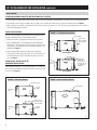
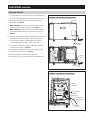
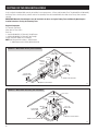
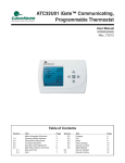
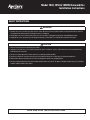
SET UP DEHUMIDIFIER FOR INSTALLATION
IMPORTANT: Cut the strap securing the compressor
shipping support bracket and remove the strap and shipping bracket.
See Figure 1.
Figure 1 – Remove Shipping Bracket
REMOVE SHIPPING BRACKET
CLIP OFF
PLASTIC STRAP
90-1908
3
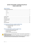
SET UP DEHUMIDIFIER FOR INSTALLATION (continued)
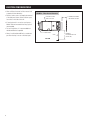
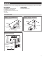
DUCT COLLARS
standard basement and attic installations (fully ducted)
•Use the screws in the parts bag to attach the duct collars to the inlet and outlet of the dehumidifier. The outlet collar has a backflow damper.
•The outlet duct collar may be attached to the top or end of the unit. Move the outlet cover to the location not being used. See Figure 2.
•Make sure there are no bends in the ductwork coming off the outlet for a minimum of 4”. This will ensure that the ductwork will not interfere
with the backflow damper function.
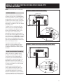
closet installations
Figure 2 – Fully Ducted Installations
Use the screws provided in the parts bag to attach the duct collars if
desired or required based on recommendations below:
OUTLET COVER
OUTLET DUCT
COLLAR W/BACK
DRAFT DAMPER
•Where inlet space is restricted, the inlet duct collar is optional.
•When the dehumidifier is installed below the HVAC equipment
and requires a vertical discharge, move the top access panel to the
end of the unit. The outlet duct collar with backflow damper is not
required. See Figure 3.
INLET
DUCT
COLLAR
•When the dehumidifier requires a ducted vertical discharge,
remove the top access panel and remount on the outlet of the unit.
Install the outlet duct collar with backflow damper on top of the
unit. See Figure 3.
END DISCHARGE
MOVE OUTLET
COVER AND
INSTALL OUTLET
DUCT COLLAR TO
TOP DISCHARGE
LOCATION
INLET
DUCT
COLLAR
crawl space, SEALED ATTICS or
basement installations
If dehumidifying the space in which the dehumidifier is installed, the
duct collars do not need to be installed. Leave the outlet cover on top
of the unit. See Figure 4.
TOP DISCHARGE
90-1909
Figure 3 – Closet Installations
Figure 4 – Non-ducted Installations
UNDUCTED OUTLET
UNDUCTED
INLET
OUTLET COVER
OUTLET
COVER
OUTLET DUCT
COLLAR W/BACK
DRAFT DAMPER
UNDUCTED
INLET
OUTLET
COVER
90-1910
4
90-1911
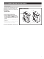
SET UP DEHUMIDIFIER FOR INSTALLATION (continued)
CONTROL LOCATION
The on-board control can be located on the top of the
dehumidifier or can be relocated to the front of the
dehumidifier if the control can not be seen/accessed in
the top orientation.
To move the control:
1.Remove the front control panel cover.
2.Remove the filter access door and filter.
Figure 5 – Control Location
CONTROL
CONTROL
PANEL COVER
CONTROL
CONTROL
PANEL COVER
3.Detach the on-board control by removing the four
(4) screws around the control. NOTE: Use one hand
to support the bottom of the on-board control when
removing.
4.Keep the control in the unit and relocate to the front
access hole.
5.Secure the control with the same four screws used
to attach the control to the top of the unit.
6.Secure the control panel cover to the top of the unit.
FILTER ACCESS DOOR
90-1884
5
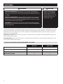
HARD WIRING
WARNING
CAUTION
ELECTRICAL SHOCK HAZARD: 115-volts may cause serious injury or death from
electrical shock. Disconnect and tag electrical service before starting installation or
field-service. Leave electrical service disconnected until installation or field-service
is complete.
ELECTRICAL SHOCK HAZARD: An interrupted or broken ground may cause property
damage, serious injury or death should an electrical fault occur. The cabinet must
be grounded in accordance with NEC ANSI/NFPA 70-2011 or local codes. In Canada,
refer to Canadian Electrical Code CSA C22.1.
Use of an undersized circuit
breaker may cause property
damage and/or the need for
mold remediation service. See
Specifications for wire and
circuit breaker sizing.
FIRE HAZARD: Use of improper wire may cause serious injury, property damage or
death due to fire. Do not use aluminum wire for electrical service to the dehumidifier.
Use only copper wire.
The Model 1830 dehumidifier can be modified for applications where hard wire power to 115VAC is required; the Model 1850W must be hard
wired. An electrical disconnect switch can be installed as needed to comply with appropriate codes or ordinances. The ON/OFF switch on the
dehumidifier interrupts the 115VAC service to the internal components of the dehumidifier, but does not disconnect the power supply at the
115VAC terminals on the dehumidifier.
United States Installations: Make all electrical connections in accordance with the current edition of the NEC ANSI/NFPA 70 and any local
codes or ordinances that may apply.
Canada Installations: Make all electrical connections in accordance with the current edition of the Canadian Electrical Code CSA C22.1 and
any local codes or ordinances that may apply.
ELECTRICAL SPECIFICATIONS FOR HARD WIRING MODEL 1830 & 1850W
Model 1830
Model 1850W
110-120 VAC, 60 Hz, 1 phase
110-120 VAC, 60 Hz, 1 phase
Minimum Circuit Capacity
9A
12A
Maximum Fuse or Circuit Breaker Amps
16A
20A
Minimum Wire Size AWG
14
14
Voltage
6
HARD WIRING (continued)
WIRING INSTRUCTIONS
1.Disconnect electrical service at the main fuse or circuit breaker box.
2.Install any code required electrical disconnects to the line service.
FIGURE 6 – Electrical Service Box Location
3.Remove the side panel and electrical service panel from the
dehumidifier. See Figure 6.
SIDE PANEL
4.
Model 1830 only: Disconnect the power cord connections from
the terminals in the electrical service box. See Figure 7.
5.
Model 1830 only: Use pliers to pinch the strain relief and pull it
out of the dehumidifier cabinet along with the power cord. See
Figure 6.
6. R oute the service cable through the 7/8” diameter hole where the
power cord was removed. USE ONLY COPPER SUPPLY WIRES.
7.Secure the cable/conduit to the dehumidifier using fittings/
connectors approved for the type of cable/conduit used.
ELECTRICAL
SERVICE BOX
8.Connect the ground wire of the service cable to the ground lug in
the electrical service box. See Figure 7.
9.Connect the line voltage wires of the service cable to the LINE
BLK and NTRL WHT terminals. See Figure 7.
10.Reattach the electrical service panel and side panel.
STRAIN
RELIEF
11.Restore electrical service at the main fuse or circuit breaker box.
POWER CORD
90-1900
FIGURE 7 – Hard Wire to 115 VAC Service
ELECTRICAL
SERVICE BOX
LINE
VOLTAGE
NEUTRAL
GROUND
115V AC WIRING
TERMINALS
GROUND LUG
LINE SERVICE
CABLE/CONDUIT
FITTING AS
REQUIRED
90-1902
7
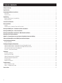
LOCATION CONSIDERATIONS
•Allow sufficient clearance for filter removal and
to prevent airflow obstruction
•Electrical service access will require the removal
of the side panel shown. Allow sufficient space
for service on this side of the unit.
Figure 8 – Filter Access Clearance
ELECTRICAL SERVICE
ACCESS THIS SIDE
6" MINIMUM CLEARANCE
FOR PROPER AIR FLOW
•If locating the unit in an attic or crawl space, a
Model 76 Control mounted in the living space is
recommended.
•For attic installations, it is recommended that
the dehumidifier be suspended.
•Always install the dehumidifier in a condensate
pan when locating in or over a finished space.
6 FT. POWER CORD
FILTER
13" MINIMUM
CLEARANCE FOR FILTER
(EITHER SIDE)
TOP VIEW
90-1840
8
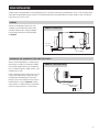
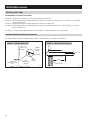
DRAIN INSTALLATION
The drain outlet on the dehumidifier can be hard piped using 3/4” nominal drain tubing or the provided fittings and 1/2” clear PVC tubing can be
used to drain the dehumidifier. Always maintain a constant downward slope from the dehumidifier to the drain and do not allow soft tubing to
curl up which may result in air lock.
LEVELING
The feet can be adjusted to level the unit, and
if required, to accommodate drain fittings and a
secondary condensate pan. Leveling is required
to ensure proper drainage from the dehumidifier.
See Figure 9.
Figure 9 – Level the Unit
0.38" MIN
2.00" MAX
3/4” DRAIN
90-1885
CONDENSATE PAN, CONDENSATE PUMP AND FLOAT SWITCH
Install a condensate overflow safety switch (i.e. float
switch) in the condensate pan, remove the factory
installed jumper wire between the Float Switch
terminals on the control and wire the float switch to
the dehumidifier as shown in Figure 10. Overflow
safety switches on condensate pumps can be wired
to the Float Switch terminals in a similar fashion.
Figure 10 – Float Switch Wiring
FLOAT DH DH
Switch
Always install the dehumidifier in a condensate pan
when locating in or above a finished space. Adhere
to local codes regarding draining of the condensate
pan. If a condensate pump is needed, install it in the
condensate pan as well.
NORMALLY CLOSED
FLOAT SWITCH
90-1857
9
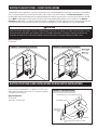
DUCTING TO HVAC SYSTEM – BASEMENT AND ATTIC INSTALLATIONS
The Preferred Installation is to duct the dehumidifier to pull air from and return dehumidified air to the HVAC return duct. This installation will
ensure warm, dehumidified air is thoroughly mixed with the HVAC system air before being discharged into the living space. Alternatively, the
dehumidifier can be ducted to discharge to the supply duct, but the external static pressure of the HVAC system must not exceed 0.4”w.c. for the
1830 and 0.6”w.c. for the 1850/1850W.
Required Component
10” Ductwork
Figure 11 – Preferred Basement Installation
Figure 12 – Alternate Basement Installation
Model 1850(W)
0.6” w.c. MAX
Model 1830
0.4” w.c. MAX
10” DUCT
AIR IS DISCHARGED
TO SUPPLY DUCT
HVAC /FURNACE
AIR IS PULLED
FROM AND
SUPPLIED TO THE
RETURN DUCT
HVAC/ FURNACE
6 ft
MIN
AIR IS
PULLED FROM
RETURN DUCT
DEHUMIDIFIER
10” DUCT
90-1886
Figure 13 – Preferred Attic Installation
90-1887
Figure 14 – Alternate Attic Installation
Model 1850(W)
0.6" w.c. MAX.
PLENUM BOX OR Y-FITTING
AIR HANDLER
Model 1830
0.4" w.c. MAX.
PLENUM BOX
6 FT. MIN.
PLENUM
AIR HANDLER
FILTER
10" DIA. INSULATED DUCT
BOTH SIDES
90-1888
24" MIN.
CONDENSATE PAN
10" DIA. INSULATED DUCT
BOTH SIDES
FILTER
CONDENSATE PAN
90-1889
Ducting Notes:
•Use insulated duct when the dehumidifier is located in an unconditioned space such as an attic or a garage.
•Use a minimum of 12” of flex duct at the dehumidifier inlet and outlet to prevent vibration noise transmission.
•When ducting return to return (preferred), the dehumidifier must be wired to turn on the HVAC fan when operating (see page 14).
•When ducting return to supply, allow adequate space before the first branch duct to ensure the warm dehumidified air is thoroughly mixed
with the HVAC system air.
10
DUCTING TO HVAC SYSTEM – CLOSET INSTALLATIONS
The dehumidifier in these applications is typically installed under or next to the HVAC equipment. In both types of installation, the dehumidifier
inlet is not ducted and pulls from the living space through a grille or louvers in the HVAC closet door. The Preferred Installation is to locate
the dehumidifier under the HVAC equipment and supply dehumidified air through the alternate outlet on the top of the unit directly to the HVAC
return. NOTE: The dehumidifier must be wired to activate the HVAC fan during dehumidifier operation in this installation. In the Alternate
Installation the dehumidifier is located next to the HVAC equipment and ducted to the HVAC supply duct using the outlet on the top of the unit.
The supply side external static pressure of the HVAC system must not exceed 0.4”w.c. for the 1830 and 0.6”w.c. for the 1850/1850W.
CAUTION
When installing the dehumidifier as part of a combustion type furnace (gas, oil, propane, etc.) HVAC system located in a closet,
duct or locate the dehumidifier inlet and outlet and seal as needed to separate the circulation air from the combustion and
ventilation air. Follow all local and national building and safety codes when installing or modifying any HVAC system.
Optional Component
10” Ductwork
Figure 15 – Preferred Closet Installation
Figure 16 – Alternate Closet Installation
Model 1850(W)
0.6” w.c. MAX
Model 1830
0.4” w.c. MAX
HVAC
HVAC
90-1891
90-1890
DUCTING FOR STAND ALONE INSTALLATIONS OR NON-DUCTED INSTALLATIONS
In this installation the dehumidifier is not ducted to the HVAC system
and is used to dehumidify a specific area. This installation is typically
in basements or crawl spaces.
FIGURE 17 – Stand Alone Ducted
DEHUMIDIFIED AIR IS SUPPLIED TO DUCTED SPACE
Optional Components
10” Ductwork
Grilles with 10” Duct Collars
DEHUMIDIFIED SPACE
10' MIN
AIR IS PULLED
FROM DUCTED
SPACE
DEHUMIDIFIER
GRILLE WITH 10" DUCT COLLAR (2 PLACES)
90-1893
11
DUCTING FOR TWO ZONE INSTALLATIONS
In this installation the dehumidifier controls the humidity in two separate zones, a Primary and Secondary Zone. The dehumidifier will dehumidify
the Primary Zone as the first priority, and will switch to the Secondary Zone after the dehumidification needs of the Primary Zone have been
satisfied.
IMPORTANT: Normally Closed dampers must be installed in the ducts serving the Primary Zone and Normally Open dampers
installed in the ducts serving the Secondary Zone.
Required Components
10” Ductwork and Fittings
Grilles with 10” Duct Collars
Drain Line
2 – Aprilaire Model 6510, 10” Normally Closed Damper
2 – Aprilaire Model 6610, 10” Normally Open Damper
24 VAC Transformer (40VA min.) for Dampers
NOTE: 5 442 Basement Kit includes 2 – 6510 Dampers,
2 – 6 610 Dampers and a 24VAC (40VA) transformer
FIGURE 18 – Whole-Home Primary Zone Installation
SUPPLY DUCT
TO / FROM
PRIMARY ZONE
RETURN
DUCT
NORMALLY
CLOSED
DAMPERS
6 ft
MIN
SUPPLY TO
SECONDARY ZONE
RETURN FROM
SECONDARY ZONE
NORMALLY OPEN DAMPER
NORMALLY OPEN DAMPER
90-1875
FIGURE 19 – Whole-Home Secondary Zone Installation
TO / FROM
SECONDARY ZONE
RETURN
DUCT
RETURN FROM
PRIMARY ZONE
NORMALLY
OPEN
DAMPER
SUPPLY DUCT
NORMALLY
OPEN
DAMPER
SUPPLY TO
PRIMARY ZONE
NORMALLY CLOSED DAMPER
NORMALLY CLOSED DAMPER
90-1895
12
MODEL 76 – EXTERNAL CONTROL OR CRAWL SPACE/SEALED ATTIC
CONTROL AND WIRING
NOTE: Use 18-22 AWG wire for control wiring.
FIGURE 20 – Model 76 External Control Wiring
EXTERNAL CONTROL
NC NO
FLOAT DH DH
Switch
+ - A B ODT VENT DEH
Remote Sensor Dampers
Gh Rf Cf Gs W Y
HVAC EQUIP.
Used as an external control, the Model 76 is
mounted in the space that is to be dehumidified.
When the dehumidifier is powered, the display on
the dehumidifier control will show “EXTERNAL”
to indicate that an external control is being used.
External controls are recommended when the
dehumidifier is installed in an attic and is ducted
to the HVAC system.
NO/NC SWITCH
The Model 76 uses a normally open (NO), dry
contact (i.e. not a triac or other semiconductor)
relay to complete the circuit between the DH
terminals of the dehumidifier control. If using
other controls such as a thermostat with
dehumidification outputs, ensure the output is a
dry contact type and set the NO/NC switch on the
dehumidifier control (see Figure 20) to correspond
with the control being used. The Aprilaire Model
8620 Thermostat or Model 8910 Home Comfort
Control are recommended alternate controls and
both use normally open contacts.
If an external control is used in a zoned
application, it must be located in the Primary
Zone (refer to TWO ZONE – PRIMARY AND
SECONDARY ZONED INSTALLATION on page 18
for details).
Used as crawl space or sealed attic control
(or remote control), the Model 76 is mounted
in the living space while the dehumidifier is
located in the area to be dehumidified. When
the dehumidifier is powered, the display on the
dehumidifier control will show “REMOTE” to
indicate that a remote control is being used. The
RH shown on the Model 76 is the RH measured
at the dehumidifier.
Remote control is typically used for crawl
space or sealed attic applications, but is also
recommended when the dehumidifier and the
space being dehumidified are inconvenient or
difficult for the homeowner to access. Examples
of this type of application include basements that
may be inconvenient to access or storage areas.
A
B
C/R/+
DH
DH
90-1862
FIGURE 21 – Model 76 Crawl Space/Sealed Attic (Remote) Wiring
+ - A B ODT
Remote Sensor
Gh Rf Cf Gs W Y
HVAC EQUIP.
CRAWL SPACE/SEALED ATTIC CONTROL
MODEL 76 CONTROL
MODEL 76 CONTROL
A
B
C/R/+
DH
DH
90-1860
13
WIRING THE DEHUMIDIFIER TO THE HVAC SYSTEM AND ZONE DAMPERS
NOTE: Use 18-22 AWG wire for wiring to HVAC system and zone
dampers.
FIGURE 22 – Wiring to HVAC System
Pull off the wiring access cover near the dehumidifier control to
access the wiring terminals. Snap the wiring access cover back into
place after completing all wiring.
WIRING TO THE HVAC SYSTEM
FLOAT DH DH
Switch
When the dehumidifier is ducted to the HVAC system, it is
recommended that it also be wired to the HVAC system as shown
in Figure 22. If ducted to the HVAC system in return to return
configuration, the dehumidifier must be wired to the HVAC system
to prevent short circuiting dehumidified air directly back to the
dehumidifier inlet. In return to supply ducting configuration, running
the HVAC fan with the dehumidifier ensures the warm dry air is mixed
with room air before being discharged to the home.
EXISTING WIRE
NEW WIRE
Gh Rf Cf Gs W Y
HVAC EQUIP.
+ - A B ODT VENT DEH
Remote Sensor Dampers
OPTIONAL
WIRES
HVAC
EQUIPMENT
Optional W & Y Wiring
THERMOSTAT
Wire the W and/or Y terminal to the HVAC system when using the
ventilation feature of the dehumidifier (see VENTILATION on page 19).
Wire the dehumidifier Y terminal to the HVAC system if it is desired
to disable the dehumidifier compressor from operating when the air
conditioning is running. See DEH w/AC in SYSTEM SET-UP on
page 17 for additional set up steps required to access this feature.
R
C
G
W
Y
G
R
C
W
Y
90-1859
WIRING TO ZONE DAMPERS
FIGURE 23 – Two Zone Wiring On-Board Control
FLOAT DH DH
Switch
Gh Rf Cf Gs W Y
HVAC EQUIP.
+ - A B ODT VENT DEH
Remote Sensor Dampers
(40 VA min)
24 VAC
(PRIMARY ZONE)
NORMALLY CLOSED
(SECONDARY ZONE)
NORMALLY OPEN
90-1896
14
SYSTEM SET-UP & CHECKOUT
If dehumidifier installation does not include ventilation or zoning and
will not be wired to an external control, remote control or the HVAC
system, proceed to Installer Test Mode section on page 17.
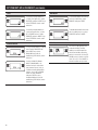
Ventilation
If not using the dehumidifier to
bring in outdoor air, press MODE
to go to ZONE screen selections.
1.Check all wiring.
2.Make sure the wire access cover has been snapped back onto the
on-board control.
90-1854
3.Plug unit in and turn power switch to ON.
If using the dehumidifier for
ventilation, Enable and press
MODE to select TIMED or AUTO.
4.The on-board control screen should display OFF.
90-1854
If ventilating based on time
only (no outdoor temperature
restrictions), press MODE at the
VENT TIMED screen to go to
ventilation time selection screen.
90-1854
NOTE: If the display backlight is not on, the first button press (any
button) will only turn on the backlight. Press the button a second time
to achieve function.
5.Hold the MODE button on the on-board control for 3 seconds to
enter the Installer Set-up Menu.
6.Navigate through the following screens to set up the dehumidifier
for the installed application.
Use the UP or DOWN arrows to select items and use MODE to
switch to the next set-up option. To exit installer set-up, all options
must be scrolled through using the MODE button.
90-1854
If ventilating with outdoor temperature restrictions, use the UP arrow
to go from VENT TIMED to VENT AUTO –B and then the UP/DOWN
arrows to select the desired ventilation mode, B, C, or D. Press MODE
to go to the ventilation time selection screen.
7.After the installer set up options have been completed, DONE will
blink for 3 seconds and the control will return to the OFF screen.
90-1854
90-1854
Vent-Auto-C: Ventilation
prevented when outdoor
temperature is below 0°F and
above 100°F.
90-1854
Remote Control – Crawl Space/Sealed Attic
90-1854
If not installing in a crawl space
or sealed attic with Model 76
remote control, press MODE to go
to VENT screen selections
90-1854
90-1854
90-1854
If installing in a crawl space or
sealed attic with remote control,
Enable and press MODE. The
installer set-up is complete,
proceed to Installer Test Mode
section on page 17.
Vent-Auto-B: Ventilation
prevented when outdoor
temperature is below 0°F and
above 100°F. Between 0°F – 20°F
ventilation is only allowed during
a HVAC heat call.
Vent-Auto-D: Ventilation
prevented when outdoor
temperature is below 0°F and
above 90°F. Between 0°F – 40°F
ventilation is only allowed during
a HVAC heat call.
Vent-Auto-B, -C, -D modes apply outdoor temperature limits and
require an outdoor temperature sensor to be installed.
Press the UP or DOWN arrows
to adjust the ventilation time per
hour from 0 to 60 minutes. After
selecting time, press MODE to go
to the ZONE screen selections.
90-1854
15
SYSTEM SET-UP & CHECKOUT (continued)
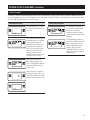
Zone
DEH W/AC
If installing the dehumidifier in
a single zone application, select
DISABLED and press MODE to go
to the EXTERNAL control screen
selections.
To allow dehumidification during
active air conditioning, select
ENABLED and press MODE.
90-1854
90-1854
90-1854
If installing the dehumidifier in
a two-zone application, use the
UP or DOWN arrows to select
ENABLED and press MODE to go
to the EXTERNAL control screen
selections.
90-1854
RH Offset
External Control
90-1854
90-1854
16
To disable dehumidification when
the air conditioning is on, select
DISABLED and Press MODE.
If using the dehumidifier on-board
control select DISABLED and
press MODE to go to the
dehumidificaiton with air
conditioning (DEH W/AC) screen
selections.
If using a Model 76, Model
8910, or Model 8620 as an
external control or other thirdparty external control, such as
a thermostat with dehumidifier
outputs, use the UP or DOWN
arrows to select ENABLED
and press MODE to go to
the dehumidification with air
conditioning (DEH W/AC) screen
selections.
90-1854
An offset can be applied to the
on-board humidity humidity
reading to avoid discrepancies
with other humidity measuring
devices in the home. Use the UP/
DOWN arrows to select an offset
from -5% to 5%. Press MODE to
exit the installer set-up screens.
SYSTEM SET-UP & CHECKOUT (continued)
Installer Test Mode
If everything is properly wired, the dehumidifier and all of the wired components will turn on and off during Installer Test Mode to demonstrate
that all are properly operating. Installer Test Mode lasts for four (4) minutes. If the ON/OFF button is pressed during test mode, the dehumidifier
will exit Installer Test Mode and return to the OFF screen.
Dehumidification Only
Zoning and/or Ventilation
If the dehumidifier is not already
OFF, press the ON/OFF button to
turn it off.
90-1854
90-1854
90-1854
Press and hold the ON/OFF button
and MODE buttons for 3 seconds.
The measured humidity, AIR
SAMPLING and TEST will show
on the display. If wired to the
HVAC system, the HVAC blower
will turn on and if there is/are
damper(s) wired to the DEH
DAMPER terminals of the control,
the damper(s) will energize.
90-1854
If the dehumidifier has been set
up for ventilation, VENTILATING
will appear on the display
throughout Installer Test Mode,
and the ventilation damper will be
energized.
If the dehumidifier has been set
up for zoning, PRIMARY ZONE will
show on the display for the first
minute of dehumidifier blower
operation. After one minute,
SECONDARY ZONE will show on
the display and the zone dampers
will de-energize.
After three (3) minutes the
dehumidifier compressor will
turn on and DEHUMIDIFYING will
replace AIR SAMPLING on the
control screen.
90-1854
After one minute of compressor
operation, all outputs will turn off
and DONE will blink for 3 seconds
and then return to the OFF screen.
90-1854
90-1854
17
START UP AND SEQUENCE OF OPERATION
SINGLE ZONE WHOLE HOUSE OR STAND ALONE USING
THE DEHUMIDIFIER CONTROL
1.Press the ON/OFF button to turn the dehumidifier control ON. The
display will show the current setting, and the dehumidifier blower
and HVAC blower (if wired to the HVAC system) will turn on to
start sampling the air.
The setting will be replaced by the measured humidity and “AIR
SAMPLING” will show on the display.
2.Use the UP or DOWN button to adjust the humidity setting as
desired. The recommended initial setting is 59%.
3.After three (3) minutes of sampling, the measured humidity will be
compared to the setting:
CRAWL SPACE OR SEALED ATTIC (REMOTE) CONTROL
USING MODEL 76
1.Press the ON/OFF button to turn the dehumidifier control ON.
“REMOTE” will show on the display to indicate that a remote
control is wired to the dehumidifier.
2.At the Model 76, press the ON button; the Model 76 will display
the RH measured at the dehumidifier, and the dehumidifier blower
will turn on to start sampling the air.
3.Use the UP or DOWN button on the Model 76 to adjust the dryness
level as desired. The dryness levels are from 1 to 7, with 1 being
least dry and 7 being most dry; the recommended initial setting is
3.
a. If the humidity is above the setting, the dehumidifier
compressor turns on and “AIR SAMPLING” will be replaced
by “DEHUMIDIFYING”. The compressor remains on until the
measured humidity falls 3% RH below the setting.
4.After three (3) minutes of sampling, the measured humidity will be
compared to the setting:
b. If the measured humidity is below the setting, the blowers turn
off and the display returns to showing the RH setting.
b. If the measured humidity is below the setting, the dehumidifier
blower turns off.
4.The dehumidifier will sample again every 60 minutes, or at any
time if the humidity setting is lowered.
5.The dehumidifier will sample again every 60 minutes, or at any
time if the dryness level is increased.
SINGLE ZONE WHOLE HOUSE OR STAND ALONE USING
MODEL 76 EXTERNAL CONTROL
a. If the humidity is above the setting, the dehumidifier compressor
turns on and “ON” flashes on the Model 76 display.
TWO ZONE – PRIMARY AND SECONDARY
1.Press the ON/OFF button to turn the dehumidifier control ON.
1.Press the ON/OFF button to turn the dehumidifier control ON.
“EXTERNAL” will show on the display to indicate that an external
control is wired to the dehumidifier.
2.At the Model 76, press the ON button; the Model 76 will display
the measured RH.
3.Use the UP or DOWN button on the Model 76 to adjust the
humidity setting as desired. The recommended initial setting is
59%.
4.If the RH measured by the Model 76 rises above the setting,
the dehumidifier will turn on as will the HVAC blower (if wired
to the HVAC system). “DEHUMIDIFYING” will appear on the
dehumidifier control display to show that the Model 76 is calling
for dehumidification. The dehumidifier and HVAC blower (if on)
will turn off when the RH measured by the Model 76 drops 3% RH
below the setting.
Dehumidification of the Primary Zone follows the same sequence
as described to the left for Single Zone, with or without a Model
76 external control installed in the Primary Zone. The dehumidifier
control display will show “PRIMARY ZONE” in addition to
that described to the left when sampling or dehumidifying the
Primary Zone. The zone dampers are energized when sampling or
dehumidifying the Primary Zone.
2.The Secondary Zone uses the humidity setting on the dehumidifier
control. During Secondary Zone sampling or dehumidification, the
zone dampers are de-energized and the HVAC blower (if on) stops.
“SECONDARY ZONE” will show on the dehumidifier control display
when the Secondary Zone is either sampling or dehumidifying. If
the Primary Zone had just finished a dehumidification demand, the
compressor will continue to run during Secondary Zone sampling to
prevent short cycling of the compressor.
The Secondary Zone is sampled immediately after the Primary Zone
has finished sampling, or if there is a call for dehumidification from
the Primary Zone, immediately after the call has been satisfied.
When a Model 76 external control is installed, the Secondary
Zone will be sampled once per hour if there has not been a call for
dehumidification from the Primary Zone. Secondary Zone sampling
will also occur whenever the setting on the dehumidifier control is
lowered.
18
VENTILATION
The dehumidifier can activate a normally closed damper to bring in outdoor air through a fresh air intake duct. This feature can not be used when
a Model 76 has been installed in a Remote Control application, and is not recommended for two-zone installations.
Required Components
Aprilaire Model 6506, Normally Closed Damper
6” Insulated Duct for Fresh Air Intake Duct
24 VAC Transformer (10VA min.) for Ventilation Damper
Intake Hood
18-22 AWG Wire
Optional Components
8052 Outdoor Temperature Sensor
INSTALLATION & WIRING
FIGURE 24 – Single Zone, On-Board Control
Ventilation Installation
FIGURE 25 – Single Zone, External Control
Ventilation Installation
AIR IS PULLED
FROM OUTSIDE
AIR IS PULLED
FROM OUTSIDE
6 ft
MIN
NORMALLY CLOSED
VENT DAMPER
NORMALLY CLOSED
VENT DAMPER
6 ft
MIN
HVAC/ FURNACE
HVAC / FURNACE
BALANCING
DAMPERS
90-1897
90-1898
FIGURE 26 – Ventilation Wiring
FLOAT DH DH
Switch
HVAC
EQUIPMENT
OPTIONAL OUTDOOR
TEMPERATURE SENSOR
(Model 8052)
6" NORMALLY
CLOSED DAMPER
Gh Rf Cf Gs W Y
HVAC EQUIP.
+ - A B ODT VENT DEH
Remote Sensor Dampers
Y
W
24 VAC
(10 VA min)
TRANSFORMER
C
R
G
Y
W
G
C
R
THERMOSTAT
90-1861
19
VENTILATION (continued)
VENT-AUTO & VENT-TIMED
The dehumidifier can ventilate in four modes.
Vent-Timed:Ventilation occurs based only on time setting; no temperature restrictions.
Vent-Auto-B:Ventilation prevented when outdoor temperature is below 0°F and above 100°F. Between 0°F – 20°F ventilation is only allowed
during a HVAC heat call.
Vent-Auto-C:Ventilation prevented when outdoor temperature is below 0°F and above 100°F.
Vent-Auto-D:Ventilation prevented when outdoor temperature is below 0°F and above 90°F. Between 0°F – 40°F ventilation is only allowed
during a HVAC heat call.
Vent-Auto-B, -C, -D modes apply outdoor temperature limits and require an outdoor temperature sensor to be installed.
OUTDOOR TEMPERATURE SENSOR INSTALLATION
The Outdoor Temperature Sensor should be installed outside in a shaded location, or in the outdoor air intake duct.
Figure 27 – ODT Mounted Outside
NORTH, EAST
OR WEST SIDE
OF HOME
Figure 28 – ODT Mounted in Intake Duct
OUTDOOR
TEMPERATURE
SENSOR
CENTER LINE
SENSOR
OUTDOOR
TEMPERATURE SENSOR
LEADS
ABOVE EXPECTED
SNOW LINE
SENSOR
BRACKET
36" MAX .
OUTSIDE WALL
B2202617-D
20
B2202617-E
VENTILATION (continued)
DETERMINE VENTILATION REQUIREMENTS
CALCULATING AIRFLOW REQUIREMENT
Table 1 – CFM Required
1.The MINIMUM ventilation requirement is calculated using ASHRAE
62.2-2010.
House Sq. Ft.
ASHRAE Airflow in CFM = [House Area in Sq. Ft. x 0.01] +
[(Number of Bedrooms +1) x 7.5]
N
OTE: Use ‘Number of Bedrooms + 1’ or ‘Number of Occupants’,
whichever is larger.
2.Table 1 shows the calculated airflow values to the nearest 5 CFM.
3.Record the required CFM. ________
Number of Bedrooms
2
3
4
5
6
1000
35
40
50
1500
40
45
55
60
70
2000
45
50
60
65
75
2500
50
55
65
70
80
3000
55
60
70
75
85
75
80
90
3500
DETERMINE FRESH AIR DELIVERY RATE
1.Measure the negative static pressure of the return system at the location where the fresh air intake duct enters the return duct or dehumidifier
inlet.
2.See Table 2 for estimated inlet airflow in CFM, based on duct type, length and available negative pressure. Use an airflow measuring device
for a more accurate airflow delivery rate.
3.Record the delivered CFM. ________
Table 2 – CFM Delivered
Negative Static Pressure (“w.c.) as Measured for Return Duct or Plenum
Duct Length
0.05
0.1
0.15
0.2
0.25
0.3
Flex
Pipe
Flex
Pipe
Flex
Pipe
Flex
Pipe
Flex
Pipe
Flex
Pipe
10 ft.
60
65
85
90
105
110
120
125
135
140
150
160
20 ft.
55
60
80
85
100
105
115
120
130
135
140
150
30 ft.
50
55
75
80
95
100
110
115
125
130
130
140
NOTE: For the table above, 6” flex duct is laid loose with two, wide 90° bends and a fully opened damper. Rigid pipe values are based on 6”
duct, two 90° elbows, and a fully open damper. In both cases, the air intake is through a metal vent hood with inlet screen. Airflow may need to
be adjusted up or down for variations in duct work.
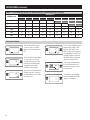
DETERMINE CYCLE TIME
1.Use the Required CFM and Delivered CFM from the above steps to determine the Cycle Time from Table 3.
2.The values highlighted in gray cannot be set due to the maximum 60 minute Cycle Time. A second ventilation device (i.e., bigger duct or
second duct) will be required to meet ventilation needs.
21
VENTILATION (continued)
TABLE 3 – Cycle Time Setting (minutes) for Airflow Delivered vs. Airflow Required for 1 hour Cycle
CFM Delivered
CFM Required
20
30
40
50
60
70
80
90
100
60
20
30
40
50
60
70
80
90
100
80
15
25
30
40
45
55
60
70
75
100
15
20
25
30
35
40
50
55
60
120
10
15
20
25
30
35
40
45
50
140
10
15
15
20
25
30
35
40
45
160
10
10
15
20
25
25
30
35
40
Installer settings
With the dehumidifier power
switch on, press the ON/OFF
button to turn the dehumidifier
off.
90-1854
90-1854
90-1854
Press and hold the MODE button
for 3 seconds to access the
installer settings menu. Press
and release the MODE button
repeatedly until the VENT
DISABLED screen appears.
Press the UP or DOWN button to
ENABLE ventilation, then press
the MODE button to set Timed or
Auto ventilation.
Press the UP or DOWN button
to set the desired amount of
ventilation time per hour from
0 to 60 minutes.
90-1854
To complete, press the MODE
button repeatedly until DONE
appears on the display.
90-1854
90-1854
22
Press the UP or DOWN to toggle
between VENT TIMED, VENT
AUTO-B, VENT AUTO-C and
VENT AUTO-D (refer to page 20
for a description of each). Press
the MODE button to select the
desired ventilation method and
adjust the ventilation time.
VENTILATION (continued)
SEQUENCE OF OPERATION
When wired as shown in Figure 26, the ventilation damper will open whenever there is an HVAC heating (W), cooling (Y) or fan (Gs) call,
allowing fresh air to be brought in when the HVAC blower is running (see VENTILATION WITH AN EXTERNAL CONTROL section below for
exceptions). The ventilation damper will also open if the dehumidifier is operating. “VENTILATING” will show on the dehumidifier control when
the dehumidifier is actively ventilating. When the HVAC call ends, the dehumidifier stops, or after the set amount of ventilation time has been
met, the ventilation damper will be closed.
If the set amount of ventilation time has not been met before the end of the one-hour cycle, the dehumidifier will turn on the ventilation damper
along with the HVAC blower to ensure the desired ventilation time is satisfied.
If the dehumidifier has been set up to operate ventilation with outdoor temperature restrictions (AUTO-B, AUTO-C or AUTO-D – refer to page 20)
then ventilation will be limited as described.
DEHUMIDIFYING THE FRESH AIR
When the dehumidifier is set up for single zone and there is no external control installed, the dehumidifier will turn on its blower and measure
the RH of the air entering the dehumidifier during ventilation when ducted as shown in Figure 24. If the relative humidity of the air entering the
dehumidifier is higher than the setting, the dehumidifier compressor will turn to remove moisture.
VENTILATION WITH AN EXTERNAL CONTROL
When an external control is installed the dehumidifier will open the ventilation damper only when there is a cooling call (Y) or when the
dehumidifier is operating, unless the ventilation need has not been met. If the set amount of ventilation time has not been met before the end
of the one-hour cycle, the dehumidifier will turn on the ventilation damper along with the HVAC blower to ensure the desired ventilation time is
satisfied.
ADJUSTING VENTILATION TIME AFTER INITIAL SET UP
1. Press the UP or DOWN button to access the RH adjustment screen or to turn on the backlight if using an
External Control.
90-1854
2. Press the MODE button to toggle to the VENT TIME setting.
3. Press the UP or DOWN button to adjust the ventilation time (minutes). After adjusted, press nothing else;
the screen will return to home screen after three (3) seconds.
90-1854
23
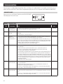
TROUBLESHOOTING
Technical Support is available Monday through Friday, 7:00 a.m. to 5:00 p.m. CST, at (800) 334-6011. Use the guides on the following pages to
identify and correct system faults. Contact Technical Support before replacing the unit or any components and for additional troubleshooting.
DIAGNOSTIC CODES
When an error occurs, the Diagnostic Code along with SERVICE REQUIRED
will be displayed on the control screen.
90-1854
TABLE 4 – Diagnostic Codes
Diagnostic
Code
24
Failure Mode
Action
Reset
E1
Internal Humidity or
Temperature Sensor
Open or Shorted
1.Check the connection between the sensor board and control board.
2.If connection okay, replace sensor board, Part No. 5460.
Cycle Power
E2
High Refrigeration
Pressure
1.Verify that the fan works, the backflow damper swings freely and there is no blocked or restricted
ductwork.
2.If the fault persists, call Technical Support.
Cycle Power
E3
Model 76
Remote Control
Communication Loss
1.Check connections between Model 76 and dehumidifier control board. Terminals should be fully
inserted and secured in the control board and Model 76 control terminals.
2.If connections are correct and secure, turn off the dehumidifier and remove the Model 76. Use a
short section of 4-wire cable to reconnect the Model 76 to the control board. Turn the dehumidifier
back on and increase the dryness level setting on the Model 76. If the dehumidifier turns on, the
problem is with the wiring between the dehumidifier and control.
3.If the dehumidifier does not turn on, call Technical Support.
Self-Correcting
E4
Insufficient Capacity
1.Check the frost sensor connection at the power board. Terminal should be fully seated on the
power board pins.
2.Remove the side access panel and verify that the sensor is secured to the suction line.
3.If the sensor is connected and secured to the refrigeration line proceed to the next step.
4.Reset the fault by cycling power to the dehumidifier.
5.Turn the humidity setting down (below room/home humidity level) to make a dehumidification call.
6.Allow the fan and compressor to run for approximately 10-15 minutes and then enter diagnostic
test mode by simultaneously pressing the UP ARROW and MODE buttons for 3 seconds. The LCD
will display the temperature measured by the internal sensor while also displaying AIR SAMPLING
and ON, the humidity measured by the internal sensor while also displaying %RH and ON, and the
frost sensor temperature while also displaying ON. Scroll through these values and by using the
UP/DOWN arrow buttons.
7.Record values and call Technical Support.
Cycle Power
E5
High Temperature
Thermistor Failure
1.Check the high temperature sensor connection at the power board. Terminal should be fully seated
on the power board pins.
2.Remove the side access panel and verify the sensor is not damaged and connected to the
refrigeration line coming from the compressor.
3.If the sensor is connected and secured to the refrigeration line, it may need to be replaced with
Part No. 5456 – contact Technical Support to confirm.
Cycle Power
E6
Low Temperature
Thermistor Failure
1.Check the low temperature sensor connection at the power board.
2.Remove the side access panel and verify the sensor is not damaged and connected to the suction
line.
3.If the sensor is connected and secured to the refrigeration line, it may need to be replaced with
Part No. 5455 – contact Technical Support to confirm.
Cycle Power
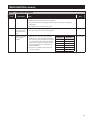
TROUBLESHOOTING (continued)
TABLE 4 – Diagnostic Codes (continued)
Diagnostic
Code
Failure Mode
Action
Reset
E7
Float Switch Open
1.Empty the condensate pan.
2.Check the float switch connection at the control board.
3.If not using a float switch, verify jumper is between float switch terminals on dehumidifier
control board.
4.If the problem persists, replace the float switch.
Self-Correcting
E8
Inlet Air Temperature
Out of 50°F – 104°F
or dew point below
40°F
1.Verify all ductwork is properly sealed.
2.If no signs of leak points, contact Technical Support.
Self-Correcting
E9
Outdoor Temperature
Sensor Open or
Shorted
1.Check the sensor connection at the power board.
2.Remove the wires from the terminals and measure
the resistance. A short circuit will have a resistance
very close to 0 Ohms and an open circuit will have
a very very high resistance. The table at right can
be used to approximate the resistance based on
outdoor temperature.
3.If the sensor is not reading correctly, replace the
sensor, Part No. 8052.
Outdoor
Temperature
Resistance
0°F
84,500 Ohms
20°F
46,000 Ohms
40°F
26,000 Ohms
60°F
15,500 Ohms
80°F
9,500 Ohms
100°F
6,000 Ohms
Self-Correcting
25
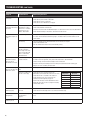
TROUBLESHOOTING (continued)
TABLE 5 – Troubleshooting Guide
Symptom
Possible Reason
Troubleshooting Procedure
Dehumidifier does not
turn on/run.
No power to unit.
• Check that the dehumidifier is plugged in.
• Check that the power switch is turned ON.
• Check that the control is turned ON.
• Check that the circuit breaker has not tripped.
Dehumidifier blower is
running but with little or
no airflow.
Pressure drop across
dehumidifier is higher
than 0.4”w.c. for Model
1830 or 0.6”w.c. for
Model 1850/1850W.
• Check dehumidifier air filter and wash or replace.
• Check for blocked duct work and clear.
• Verify that the outlet collar with backflow damper is installed on the outlet side of the dehumidifier.
• Check if backflow damper is blocked or stuck and remove obstruction.
Dehumidifier blower is
running but compressor
is not.
Float switch open.
• If float switch installed, check connections at control board and empty condensate pan.
• If no float switch installed check that the jumper is installed at the float switch terminals on the
control board.
Coil frosting.
• Lack of or reduced airflow. Check dehumidifier air filter and wash or replace.
• Check for blocked duct work.
• Inlet air conditions below 60°F. Increase the humidity setting.
Inlet air temperature is
outside of the 50°F –
104°F range or the dew
point is below 40°F and
there is a demand for
dehumidification.
• Verify all ductwork is properly sealed.
When zoned, the
dehumidifier damper
does not open in
INSTALLER TEST mode.
Incorrect damper wiring
or bad connection.
• Verify wiring between dampers and 24 VAC transformer.
• If wired for Two Zone operation, verify that 24 VAC transformer is 40 VA minimum.
• Check all wiring connections between dampers and control board.
• Verify the normally closed dampers are in the Primary Zone ductwork and the normally open
dampers are in the Secondary Zone ductwork.
The ventilation damper
does not open when the
HVAC fan is active.
Cycle time has been
met.
• The damper will not open if the Ventilation Time has already been met.
ODT error or outdoor air
outside of ODT range.
• Check that the ODT is wired correctly to the
dehumidifier control board and connections are secure.
• Check that the ODT is installed in the outdoor air
intake according to the set-up specified in the
Ventilation Section beginning on page 19.
• Remove the ODT leads from the dehumidifier control
board and check the resistance. Compare the reading
with the table shown.
Outdoor
Temperature
Resistance
0°F
84,500 Ohms
20°F
46,000 Ohms
40°F
26,000 Ohms
60°F
15,500 Ohms
80°F
9,500 Ohms
100°F
6,000 Ohms
Dehumidifier is not
draining properly.
Drain line blocked or unit • Verify that the unit is level.
not level.
• C heck the drain line blockages and for a continuous downward slope.
The HVAC fan turns on
unexpectedly.
Dehumidifier is sampling
or ventilation in
progress.
• The dehumidifier will turn on the HVAC fan during air sampling or as needed to meet the ventilation
time.
Dehumidifier is
producing hot air.
Normal function.
• Air is reheated across the condenser coil, resulting in a temperature rise between inlet and outlet.
26
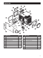
SERVICE PARTS
4
18
5
3
9
1
10
13
7
11
14
17
2
15
8
12
6
16
90-1906
19
No.
Part Description
Part No.
No.
Part Description
Part No.
Fan, 70pt Deh
5453
Fan, 95pt Deh
5467
12
Wire Harness, Power, Deh
5454
5446
13
Sensor, Low Temperature, Deh
5455
Hole Cover, UI Ctrl, Deh
5447
14
Sensor, High Temperature, Deh
5456
6
Door, Filter Access, AA Deh
5448
15
Leveling Foot, Deh
5457
7
Outlet Duct Panel, Deh
5449
16
Capacitor, 45MFD, 370VAC, 70pt/95pt Deh
5458
8
Backflow Damper, 10”, Deh
5450
Capacitor, 8MFD, 450VAC, 70pt Deh
5459
9
Inlet Duct Panel, AA Deh
5451
Capacitor, 12MFD, 450VAC, 95pt Deh
5468
10
Cover, Outlet, AA Deh
5452
18
RH Sensor, Deh
5460
19
Drain Tube + Fittings
5461
1
Filter, 10” x 12” x 1” EZK
5443
2
Internal Control Board, Deh
5444
3
User Interface Assembly, Deh
5445
4
Wiring Access Door, AA Deh
5
11
17
27
P.O. Box 1467 • Madison, WI 53701-1467 • Phone: 800/334-6011 • Fax: 608/257-4357 • www.aprilairepartners.com
10010759 2.14
B2206316A
Printed in U.S.A.
© 2014 Aprilaire – A division of Research Products Corporation