1
®
DELUXE STITCHER
C O M P A N Y
I N C .
Head Serial Number :
Date Purchased :
Where Installed:
(make/model of machine)
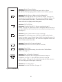
26/26D Stitcher Head
OPERATION AND MAINTENANCE MANUAL
Wire Sizes: 21-28 Ga. Round and 21x25 Flat
Crown Sizes: 5/16” (8 mm), 3/8” (9.5 mm),
1/2” (12.7mm) and 5/8” (15.9mm)
Capacity: 2 sheets to 1/4” (6.4 mm)
Before using this Stitcher Head, all operators must study this manual and follow the
safety warnings and instructions. Keep these instructions with the 26/26D Stitcher
Head for future reference. If you have any questions, contact your local DeLuxe
Stitcher Graphic Arts Representative or Distributor.
WARNING!
26/26D Stitcher Head
Machine operators and others in the work area should always wear
safety glasses to prevent serious eye injury from
fasteners and flying debris when loading, operating,
or unloading this machine.
Do not operate this stitcher head without all stitcher machine
guards in place. Do not modify the guards in any way.
Always disconnect the power supply before removing
any guards for servicing.
Never operate the machine with wire feeding through
the head unless there is stock above the clinchers,
otherwise serious damage may result.
Always turn power off when making adjustments. Always
disconnect the power cord before any disassembly work.
2
Table of Contents
Introduction . ........................................................................................................4
Part Number Definition.....................................................................................5
Specifications. .....................................................................................................6
Installation . .......................................................................................................8
Pre-Inspection .................................................................................8
Inspection ........................................................................................8
Mounting ..........................................................................................10
Operation . ........................................................................................................12
Wire Threading ................................................................................12
Wire Straightening ...........................................................................13
Adjustments and Settings . ..............................................................14
Maintenance. .......................................................................................................18
Lubrication .......................................................................................18
Cleaning ..........................................................................................19
How to Order Spare Parts................................................................20
Replacing Spare Parts......................................................................20
Troubleshooting. .................................................................................................25
Formed Staple Chart........................................................................25
Appendices . .......................................................................................................27
Exploded Drawings...........................................................................27
Part Number /Description Cross Reference.....................................37
Variable Crown and Wire Sizes.....................................................................40
Registration Card. ..............................................................................................43
Wear/Replacement Parts. ...............................................................................44
Warranty
. ........................................................................................................45
3
Introduction
The DeLuxe Stitcher Company 2001DHD Series, 2301DHD Series, 2601AHD
Series, 2601DHD and 2601 EHD Series Wire Stitcher Heads are basically identical with respect to operation. Variations occur in some of the component parts due
to adapting that basic head to single stitch and gang stitch machines and also due to
model design changes. Variations between the 2601AHD Series and the 20001DHD
Series can be recognized by a comparison of the Swivel Holders.
These heads were designed over 75 years ago, yet they still remain the most popular
stitcher head sold in the world. The 26/26D heads are reliable, durable and
economically priced.
Typical Style Uses:
2001DHD.........................................................No. 2 and No. 10 Wire Stitchers
2301DHD................................................................. No. 23 Wire Stitchers
2601EHD........................................................ No. 16E and 17E Wire Stitchers
2601DHD/2601AHD..........................................Automatic Saddle-Stitchers,
................................................................. Gang-Stitchers, Multibinders and Others
Examples of Replacement Heads for OEM Users*:
AM Graphics / Sheridan
455, 562, 690............................................................2601DSHD251/2
AM Graphics / Sheridan 705..................................... 2601DOHD251/2
Bourg .......................................................................... 2601DOHD251/2
Christensen.................................................................. 2601DSHD251/2
Macey Multibinder . ............................... 2601AOHD251/2 and 2601DSHD251/2
McCain....................................................................... 2601DCMC251/2
Pitney Bowes......................................... 2601APBHD251/2 and 2601APB2HD251/2
Rosback ...................................................................... 2601AOHD251/2
Watkiss ..................................................................... 2601AWAHD251/2
* These are just a few examples of the replacement heads available for these OEM’s.
4
Part Number Definition
The part number for each Stitcher Head can be used to define the stitcher head itself, in most
cases. The Head’s model type, mounting style, nominal wire size and crown size can all be
determined from the part number.
2601 D S HD 24 1/2
1/2 24 HD S D 2601
= Crown size in inches
= Nominal wire size
= Head
= Original Equipment Manufacturer
= Mounting, driving or component parts style
= Model type
Model Differences
Generally speaking, the following part numbers indicate which Stitcher Heads can be used as
replacement heads for your Stitcher Machine or collating system*.
• 2001 - 2-AW Stitcher
• 2301 - Model 23 Stitcher
• 2601 - 17-AW and most other saddle equipment manufacturers
• AHD - The “A” style head with a shorter Operating Spring and one-piece Swivel Holder
• AOHD, APBHD, DCMCHD, DSHD, ARHD, AWAHD - Specially designed heads for specific
manufacturers such as Pitney Bowes, McCain, Sheridan, Rosback and Watkiss.
• ASMHD - Heads for DeLuxe Stitcher Company StitchMaster and MiniStitcher machines
• BHD - Head which mounts to the stitcher machine with a “bolt,” typically on single-head
machine
• DHD - The “D” style head with three-piece Swivel Holder, and more durable Operating
Spring, Hub and Driving Slide
• EHD - Head typically used on Bostitch 17AW’s or No. 17’s
• MHD - Head specially designed for multi-head M-Series Stitchers
* These are just examples and should be used as reference only.
5
Specifications
Weight
Shipping Weight . . . . . . . . . . . . . . . 7 lbs (3.2 kg)
Physical Dimensions
Height . . . . . . . . . . . . . . . . . . . . 10-3/4” (26.3 cm)
Width
. . . . . . . . . . . . . . . . . . . . 2” (5.1 cm)
Stitching Capacity . . . . . . . . . . . . . . . . . . . Two Sheets to 1/4” (6.4 mm)
Wire Types . . . . . . . . . . . . . . . . . . . . 21 through 28 round or 21 x 25 flat
( 25 gauge round standard )
Crown Sizes
. . . . . . . . . . . . . . . . . . . . 5/16” (8mm)
. . . . . . . . . . . . . . . . . . . . 3/8” (9.5mm)
. . . . . . . . . . . . . . . . . . . . 1/2” (12.7mm)
. . . . . . . . . . . . . . . . . . . . 5/8” (15.9mm)
Minimum Head Centers
. . . . . . . . . . . . . . . . . . . 1-7/8” (47.6mm)
Stitches Per Hour. . . . . . . . . . . . . . . . . . . . 12,000
Replacement for:. . . . . . . . . . . . . . . . . . . . Interlake/Acme/Champion heads
6
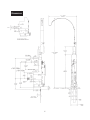
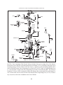
Dimensions
7
Installation
Pre-Inspection
Carefully inspect the condition of the shipping container before unpacking your 26/26D Stitcher
Head. If the container is broken or damaged and there is evidence that the stitcher head may be
damaged, immediately notify the carrier who delivered the head and the DeLuxe Stitcher Graphic
Arts Representative from whom the 26/26D Stitcher Head was purchased.
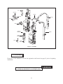
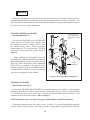
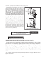
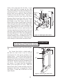
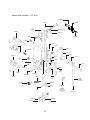
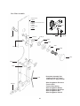
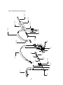
Inspection
As you carefully unpack the head, check to make sure all components were delivered and are in
good working order. Refer to Figure 1 in this manual for reference to the following pieces:
• 26/26D Manual
• Driver Release Pin
• Wire Guide Spring Assembly
• Bonnet Clamp Block and Bonnet Clamp Handle on 2601AHD, 2601DHD and
2601EHD style heads
• Bonnet Binder Stud, Bonnet Stud Pin and Bonnet Stud Nut
on 2001DHD and 2301DHD style heads
• Clincher Plate, Points and Slide (supplied with most heads)
• Driving Shaft Connector Link on 2001DHD and 2301DHD style heads
• Stitch Samples
8
2215
HN1213
9003A
2609
2133A
2624
9002
9083 (2)
9083A (2)
9073A
9086
9086A
5160
9093
9093A
Figure 1 - Assembly
Pre-Installation
Please take a few moments to fill out the registration card located on page 43 prior to beginning
installation.
Always disconnect the power supply before
making any adjustments or servicing the head.
9
! warning
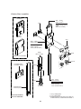
Mounting
The quality and quantity of work that can be produced by the DeLuxe Stitcher Company Heads is
dependent upon the operator making the various operating adjustments as accurately as possible. The
following illustrated instructions are provided so that the operator will clearly understand how to make
the various required operating adjustments.
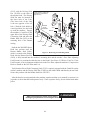
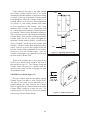
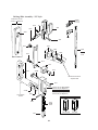
2601AHD, 2601DHD and 2601EHD
(Slot Mount/Rail Drive)
2610
To remove the 2601AHD Series, the 2601DHD
Series and the 2601EHD Series Heads, raise
the clamping Eccentric Handle (9003A) until
the Bonnet Clamp Block (9002) disengages
(approximately an 11 o’clock position). The head
can then be removed from the stitcher. Refer to
Figure 2.
When attaching the 2601AHD Series, the
2601DHD Series and the 2601EHD Series Heads to
the stitching machine, check to see that the Driving
Slide Lug (2602) and the Face Plate Adjustment
Slide (2610) are engaged in the grooves of the
stitching machine’s Driving and Adjusting Rails.
Lock the Bonnet (2601R) in position by pressing
down on the clamping Eccentric Handle.
2602
* Parts shown in outline are separated for
identification purposes
only.
9003A
2623
2601R
(BONNET)
9002
Figure 2 - Removing and Attaching Heads
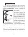
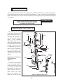
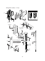
2001DHD and 2301DHD
(Bolt Mount/Crank Drive)
To remove the 2001DHD or the 2301DHD Series stitcher heads from No. 2 and No. 23 style Stitching
Machines, rotate the Drive Pulley on the stitcher machine until the Grip (9015) on the 2001DHD
or 2301DHD style head closes on the wire. Remove the Bonnet Binder Stud Nut (HN1213) and
withdraw the head from the machine. Refer to Figure 3.
NOTE: Instructions may vary with other types of Bolt Mount /Crank Drive machines.
To attach the head, rotate the Drive Pulley on No. 2 and No. 23 style Stitcher Machines manually
until the stitcher’s Driving Crank is at the top of its stroke. Engage the Driving Shaft Connecting Link
10
(2215) with the Driving Slide
Pin. (2103B) on the back of
the stitcher head. The Driving
Slide Pin must be inserted in
the lower hole of the Link.
(The lower hole of the Link
is the one opposite of the oil
hole.) With the Link held in a
vertical position, line the head
up with the machine. Engage
the machine’s Crank Pin in the
upper hole of the Driving Shaft
Connecting Link and insert the
Binder Stud Pin (2624) in the
mounting hole of the Bonnet
casting.
* Parts shown in outline are
separated for identification
purposes only.
Watkiss
style
mounting
2215
HN1213
2609
2609B
G50716
g50394 (4)
G50102
2609B
Push the the 2001DHD Series
2624
Head into position until the
Bonnet Binder Stud (2609),
Figure 3 - Removing and Attaching Heads
which is secured to the Stitcher
Head with the Bonnet Stud Pin
(2624), is fully inserted into the machine’s mounting hole and the stitcher’s Face Plate Adjusting
Link Eccentric is positioned within the hole in the Head’s Face Plate. (2132BA or 2146CA) If the
Link Eccentric is not in alignment with the hole in the Face Plate, adjust the machine’s Compression
Knob or Handle or the Face Plate until it is.
Verify that the Driver Shaft Connecting Link (2215) is squarely engaged with the Crank Pin on the
stitcher machine and the Driving Slide Pin (2103B) on the stitcher head and that they do not bind.
Secure this position with the Bonnet Stud Nut. (HN1213)
After the head is securely attached to the machine, turn the machine over manually or activate it in
jog mode, to check that the head operates freely. Until it operates freely, do not run the head under
power.
Always disconnect the power supply before
making any adjustments or servicing the head
11
! warning
Operation
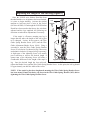
Wire Threading (Figures 4 & 5)
1. Disengage the Swivel Operating Spring (2155A)
and remove the Swivel (9038A or 9038M) from the
stitcher head.
2. Pass the wire from the Spool over the Wire
Guide Spring Assembly (2133A), between the Guide
Spring Studs (2110B) and under the flanges of the
Wire Straightener Rollers (9103) on the Spring as
well as between the Wire Straightener Eccentric
Roller (9065) and the Wire Straightener Rollers on
the Face Plate (2146CA).
3. Continue to pull the wire through the Tension
Pawl (9098) and through the hole in the Face Plate,
located at the top of the Wire Cutter (9048) Holder
and through the Swivel Holder (9043B or 2147). At
this point, do not worry if the wire is not fed between
the Grip (9015) and the Grip Holder area.
9065
2155A or
9046A
2146CA
5. With the Swivel still removed, power the stitcher
machine on and complete one cycle under power to
allow the wire to automatically thread between the
Grip and the Grip Holder. This will also cut off any
excess wire below the Cutters.
9103
9098
9015
9043B or 2147
9048
9038A or
9038M
Figure 4 - Threading the Head
Note: The Tension Pawl will hold the wire in the
Wire Straightener Roller’s (9103) groove. This
will allow the wire to feed through the Head but
not allow it to “back-up.”
4. Pull enough wire through the bottom of the
Head
to clear away what was bent in the threading
process.
9103
2133A
9065
9103
2146CA
9098
9048
Note: Hold the Swivel operating Spring away
from the Swivel Holder so as not to damage it.
9103
2133A
9038A or
9038M
2155A or
9046A
9015
9043B or 2147
Figure 5 - Threading the Head
12
Wire Straightening (Figure 6)
In order to ensure the stitches are loaded, driven and clinched properly in addition to ensuring
continuous operation of the 26 style heads, it is important that the wire enters the Swivel (9038A
or 9038M) in straight vertical line. Wire straightness is the single biggest factor for ensuring good
stitches and stitcher head reliability. Although straightness is set at the factory, every roll of wire has
varying degrees of twist which make it necessary for the user to properly straighten the wire prior to
production as well as during normal production. Follow the steps for straightening wire listed
below.
Right-to-Left Adjustment
2133A
2155A
9070
9067
9043B or 2147
9038A or
9038M
Figure 6 - Straightening the Wire
Disengage the Swivel Operating Spring (2155A)
from the Swivel (9038A or 9038M) and remove the
Swivel. Rotate the Operating Spring to a 10 o’clock
position and remove it as well. On A Style heads,
remove the Swivel Operating Hub (9163) as
well. Activate the stitcher and observe the feeding
of the wire through the Swivel Holder (9043B or
2147) and take note of the direction the wire is
moving. Use the Wire Straightener Eccentric Nut
(9067) on the Face Plate (2146CA) to adjust the
wire. If the wire is feeding to the left, turn the Wire
Straightener Eccentric Nut counter-clockwise. If the
wire is feeding to the right, turn the Eccentric Nut
clockwise. Allow enough wire to be fed through the
Head so that an accurate assessment can be made.
After an adjustment is made it take approximately
four to six stitches to take effect.
The Pointer, (9070) attached to the Wire Straightener
Eccentric Nut, and the graduated markings on the Face Plate provide a reference point for straightening
the wire. The numbers have no real value though and will vary from head to head and with each spool
of wire.
Front-to-Back Adjustment
If the wire is feeding in a straight line (left to right), but tends to curl forward or backward, turn the
Wire Straightener Adjustment Nut (9067) on the Wire Guide Spring Assembly (2133A) clockwise or
counter-clockwise as required, until the condition is remedied. After the adjustments have been made
so that the wire is feeding in a straight line, replace the Swivel and re-engage the Swivel Operating
Spring.
13
Adjusting the Length of the Left Leg (Figure 7)
2651
56
shorter
leg
Once the 26/26D style Stitcher Head has been
threaded and the wire straightness has been obtained,
it is time to begin stitching. Activate the stitcher
machine to load one piece of wire in the Swivel
(9038A or 9038M). Even though the 26/26D Stitcher
Heads have been tested at the factory, the wire draw
adjusted and the legs equalized, the following are
directions to make these adjustments if necessary.
longer
leg
9075
1060
If the staple is off-center, meaning one leg is
longer than the other, the length of the left leg has
to be changed. Loosen, do not remove, the Wire
Guide Spring Bracket Screw (9075) and the Wire
Guide Adjustment Binder Screw. (1060) Using a
screwdriver, turn the Wire Guide Spring Bracket
Screw (56) clockwise if a shorter left leg is necessary
and counter-clockwise if a longer left leg is necessary.
A slight turn of the Adjusting Screw will usually
prove sufficient to achieve the desired length. A
quarter turn of the Adjusting Screw will make a
considerable difference in the length of the staple’s
Figure 7 - Adjusting the Left Leg
leg. Once the desired length has been achieved,
tighten the Binder Screw and the Wire Guide Spring Bracket Screw. At this point, the left leg should
be approximately one half the width of the crown.
NOTE: If the staple leg has been lengthened, meaning the Wire Guide Spring Bracket Screw
has been turned counter-clockwise, tap down on the Wire Guide Spring Bracket (2651) before
tightening the Wire Guide Spring Bracket Screw.
14
Adjusting the Wire Draw
The overall length of the stitch is controlled by the amount of wire that is drawn from the spool
after each stroke of the stitcher machine. To change the overall length of the stitch, the stitcher head’s
Face Plate has be to be raised or lowered accordingly.
2001DHD Series Head (Figure 8)
more
wire
draw
Loosen the Eccentric Binder Screw found on
the stitcher machine behind the right side of the
Stitcher Head. Turn the Adjusting Link Eccentric
clockwise, which is found in the center of the
Face Plate (2146CA). The clockwise turn of the
Eccentric will raise the Face Plate, draw more wire
from the Spool and make the overall length of the
stitch longer. If the overall length of the wire is too
long, turn the Adjusting Link Eccentric counterclockwise to lower the Face Plate and decrease the
draw of the wire pulled from the Wire Spool. After
the adjustment has been made, tighten the Eccentric
Binder Screw on the stitcher machine that was
previously loosened. As a rough gauge, the distance
the Face Plate is above the Bonnet (2601B) should
be equal to the work thickness. This adjustment will
have to be made every time the compression setting
on the Stitcher Machine is changed.
2146CA
less
wire
draw
2601B
Figure 8 - Wire Draw on 2001DHD
2301DHD Series Head and other Heads without
Face Plate Adjusting Slides (Figure 9)
15
2146CA
2608
more
wire
draw
Loosen the Face Plate Locating Screw (2608) found
in the center of the Face Plate (2146CA). To increase
the overall length of the stitch, raise the Face Plate
slightly by applying pressure at the bottom edge of
the Face Plate. Use a large screwdriver as a lever
under the Wire Cutter (9048) Holder area of the Face
Plate. Raising the Face Plate draws more wire from
the Wire Spool and increases the length of each staple
leg. To shorten the staple legs or draw less wire
from the Wire Spool, lower the Face Plate slightly
by tapping the top edge of the Face Plate. After the
adjustments have been made, tighten the Face Plate
Locating Screw. As a rough gauge, the distance the
Face Plate is above the Bonnet (2601B) should be
equal to the work thickness. This adjustment will
have to be made every time the compression setting
on the Stitcher Machine is changed.
9048
less
wire
draw
Figure 9 - Wire Draw on 2301DHD
2601AHD, 2601DHD and 2601EHD Series Heads (Figure 10)
Loosen the Face Plate Adjusting Slide Nut (2613)
found in the center of the Face Plate (2146CA). To
increase the overall length of the stitch, raise the Face
Plate slightly by applying pressure at the bottom
edge of the Face Plate. Use a large screwdriver as
a lever under the Wire Cutter (9048) Holder area of
the Face Plate. Raising the Face Plate draws more
wire from the Wire Spool and increases the length of
each staple leg. To shorten the staple legs or draw
less wire from the Wire Spool, lower the Face Plate
slightly by tapping the top edge of the Face Plate.
After the adjustments have been made, tighten the
Face Plate Locating Screw. As a rough gauge, the
distance the Face Plate is above the Bonnet (2601B)
should be equal to the work thickness. As a rule, this
adjustment should only have to be made once since
this style Head automatically adjusts itself when
the compression setting of the Stitcher machine is
changed. Some minor modifications may have to be
made for individual jobs though.
Adjustment
Slide
2613
2146CA
9048
Figure 10 -Wire Draw on 2601 Series
Make sure all guards are in place before
operating the stitcher head
! warning
Adjusting the Clincher Points
2001DHD and 2601AHD, 2601DHD and 2601EHD Series Heads (Figure 11)
The final position of the Clincher Points* (round or flat, thick or thin) should be flush, or slightly
above flush, with the Clincher Plate* (round or flat, thick or thin) in order to achieve a quality stitch.
The best way to see the position of the Clincher Points is to manually turn the stitcher machine over.
When the Driver* (depending on the wire gauge being used) is at the lowest position of its stroke, the
Clincher Points are at their highest position. Turn the stitcher machine just past this point to reveal
the Clincher Points’ position. Clincher Points that do not pivot high enough will produce a weak
clinch, where Clincher Points that pivot too high will cause poor stitch quality or cut the stock being
stitched.
* For a complete list of wear parts and replacement parts based on wire gauge and crown size, see
page 46 of this manual.
16
If the clinch on the staple is not tight enough,
the Clincher Points (9083A) have to be raised,
assuming the Stitcher machine’s compression setting
is correct. If the legs of the staple are being pushed
back through the stock, the Clincher Points are set
too high and have to be lowered. These adjustments
are specific to each stitcher machine and cannot
be fully explained in this manual, since many
Machines have Clincher Lever adjustments built
in. Consult the stitcher machine’s operating manual
for complete Clincher Point adjustment instruction.
This is especially useful when using non-adjustable
Clincher Plates. If the machine is using an Adjustable
Clincher Plate, like the one shown in Figure 11,
adjust the Clincher Points as follows. Loosen the Set
Screw (UA4808.7) on the top of the Clincher Slide
(9084B). Turn the Clincher Slide Adjustment Screw
(9087) clockwise to lower the Clincher Points and
turn the Clincher Slide Adjustment Screw counterclockwise to raise the Clincher Points. Once the
Clincher Point height is set, tighten the Set Screw on
the front of the Clincher Slide.
9083A
UA4808.7
9084B
9087
Figure 11 - Adjusting Clincher Points
Refer to the complete list of wear parts for the
26/26D style Stitcher Head, found in the back of
this manual on page 50. The Clincher Points and
Clincher Plates necessary for a quality stitch are
specific to the crown size and wire gauge size used
in each stitcher head.
2301DHD Series Head (Figure 12)
flat clinch
This style stitcher head does not utilize moving
Clincher Points, but rather a solid Clincher Plate.
The legs of each stitch are bent when the wire is
pushed through the stock and hits the Clincher
Plate, as opposed to the Clincher Points in moveable
Clincher Plates coming up to meet the wire. The
resulting stitch will not lay as flat as one clinched
with moving Clincher Points though.
17
solid clinch
Figure 12 - Solid Clincher Plate
Maintenance
Your 26/26D Stitcher Head has been fully lubricated at the factory, but to insure continuous superior
operation and a longer life of the head, the operator should be sure that the heads are lubricated
regularly and carefully maintained. The operator should periodically inspect all moving parts for
signs of wear and when required, replace the worn parts. Parts such as the Wire Cutters, the Grip,
the Tension Pawl and the Driver are subject to wear and have been so designed to be reversible to
provide duplicate cutting and gripping surfaces. If after continuous usage, the original cutting or
gripping surfaces of any of these parts show signs of wear, their position in the head can be reversed,
thereby providing a new surface and lengthening the life of the part. For a complete list of wear and
replacement parts for your 26/26D style Stitcher Head, refer to page 50 in the back of this manual.
The following instructions are provided so that the operator will clearly understand how to lubricate
the Stitcher Heads and how to identify and remove any of the parts which may need to be replaced.
Always disconnect the power supply before
making any adjustments or servicing the head.
! warning
Lubrication (Figure 13)
Use any standard S.A.E. #10 oil for lubricating the heads. Heads that are in constant operation
should be lubricated daily. Heads that are operated periodically should be lubricated every five pound
wire spool change or every month, which ever comes first. Usually, only a drop of oil is required at
each lubrication point. Care must be taken that those parts of the head that contact the work to be
stitched are free of oil. Lubricate regularly instead of excessively. Excessive oiling will result in work
becoming spotted with oil. Use one drop of oil in the following lubrication points:
18
the top of the Bonnet (2601B) on either
side of the Wire Guide Spring Bracket
(2651).
•
2651
2215
the oil hole in the Swivel Operating Lever
Hub (2154).
•
•
the oil holes in the Face Plate (2146CA).
2146CA
on the Bender Bar Latch (9014) and on the
Grip (9015).
•
2156
the opening in the Swivel Holder (2147 or
9043B).
•
•
where the Clincher Points pivot.
•
the hole in the Wire Cutter (9048) Holder.
2154
9065
9098
9014
on the Wire Straightener Rollers (9065) and
Tension Pawl (9098).
•
9015
2001DHD and 2301DHD styles only
2147 or
9043B
9048
the oil hole in the Driving Shaft Connection
Link (2215)
•
2155A or
9046A
the diameter of the Swivel (9038A or
9038M)
•
9038a or
9038m
Figure 13 - Lubrication and Cleaning
Cleaning ( Figure 13)
In addition to proper lubrication, routine cleaning is important for the maintenance of your 26/26D
Head. The entire Head should be torn down and rebuilt every three months and the following areas
should be cleaned once a month:
• Swivel Assembly (9038A or 9038M): remove and wash in an oil-dissolving solvent, dry
and relubricate.
• Swivel Holder (2147 or 9043B): clean inside the Swivel hole.
• Swivel Operating Lever Hub and Stud: remove the Swivel Operating Spring (2155A or 9046A),
Lever (2151A) and/or Lever Hub (2154). Clean the Swivel Operating Spring Stud (2156) and the
hole in the Hub, relubricate and replace.
Note: Use care when replacing the Swivel Operating Lever and/or Lever Hub to avoid serious damage being done to the head.
• Anywhere that dust, oil or pieces of wire and paper have built up - for example: the Grip,
Clincher Points and around the Wire Straightener Rollers.
19
Ordering Spare Parts
In time, you will need to replace some parts in your 26/26D style Stitcher Head. When this happens,
first locate the needed part in one of the following diagrams. Then locate the DeLuxe/Bostitch part
number and contact your Graphic Arts Representative to order the part by the part number, description
and quantity.
! caution
Always power down the stitcher machine
before any maintenance or adjustments
are made to the stitcher head.
Replacing Spare Parts (Figure 14)
The following are some
of the more common wear
parts which will need to be
removed and replaced in
your 26/26D style Stitcher
Head.
Some common
replacement parts do not
require the Stitcher Head to
be removed from the stitcher
machine. These parts will
be addressed first, then a
more specific explanation
for disassembling and
replacing wear parts for the
26/26D Stitcher Head will
follow.
Removing and Replacing
the Wire Cutters
Figure 15
The Wire Cutters (9048)
have four cutting surfaces,
each of which may be used
by reversing the ends and
positioning in the Face
Plate (2132BA or 2146CA).
Worn Cutters can cause
poor stitch quality. To
change or reverse the Wire
9014
9115
9022
9113
9112
9029
9015
9026A
UA2305.2 (3)
9023
9056 (3)
9024
9009-25 or
9009-21x25
2601B
0084
9171
9051
9098
9050
9049
9048 (2)
Figure 14 - Replacing Spare Parts
20
2132ba or
2146CA
Cutters, remove them from the Face Plate. Loosen
the Screws (UA2305.2) securing the Face Plate
Clips (9056) and the Screw (0084) securing the Solid
Face Plate Clip (9171). Once the clips are loosened,
the Face Plate can be tilted away from the Bonnet
(2601B) to remove the Wire Cutters. This may be
a good time to check for wear on the Wire Cutter
Operating Slide Friction Plug (9050) and Friction
Plug Spring (9051) and replace if necessary. Slide
the existing or new Wire Cutters into the cutter
holder in the Face Plate, with the tongue of the upper
Cutter facing the Face Plate and the tongue of the
lower cutter facing the Wire Cutter Operating Slide.
Before tightening the Face Plate Clip Screws and
the Solid Face Plate Clip Screw, make sure that each
Cutter has slipped into position in the Face Plate and
in the Wire Cutter Operating Slide. (9049) Press the
Face Plate under the Face Plate Clips and tighten the
Face Plate Clip Screws. Always cycle the stitcher
machine manually before switching the power on to
ensure free mechanical movement. This will prevent
serious damage to both machine and stitcher head.
9056 (3)
9171
9048 (2)
Figure 15 - Replacing the Wire Cutters
After replacing or installing new parts, rotate the
Drive Pulley manually to check for free movement.
! caution!
Removing and Replacing the Tension Pawl (Figure
16)
The Tension Pawl (9098) is double-ended so
that when one end is worn, it can be reversed,
increasing the life of the part by providing a new
gripping surface. A worn Tension Pawl may cause
inconsistent wire draw. To remove the Tension Pawl,
disengage the Tension Pawl Spring (9134) from the
Tension Pawl and remove the Wire Straightener Roll
Clip (9124). Flip the Tension Pawl over so that a
new surface is in contact with Wire Straightener
Roller (9103) and replace the E-clip. Make sure
that the Tension Pawl is under the flange in the Wire
Straightener Roll before re-engaging the Tension
Pawl Spring. If both ends of the Pawl are worn,
replace the part.
9049
UA2305.2 (3)
9124
9098
9103
9134
Figure 16 - Removing the Tension Pawl
21
Removing and Replacing the Grip (Figure 17)
The Grip (9015) can be used in two positions so
that when the gripping teeth show signs of wear, it
may be reversed to extend the life of the part. A worn
Grip may cause inconsistent wire draw. Loosen the
Grip Retaining Clip Screw (9024) and swing the
Grip Retaining Clip (9023) out of the way. Remove
the Grip and reverse its position within the Grip
Holder. If both edges are worn, replace the part.
9015
Removing and Replacing the Driver (Figure 18)
9024
The Driver (9009-25*) is also double-ended so that
when it is worn, it can be reversed to provide a new
9023
driving surface and increase the life of the part. A
worn Driver end may cause poorly formed crowns.
Cycle the stitcher machine manually until the Driver
Figure 17 - Replacing the Grip
is at the top of its stroke. Insert the supplied Driver
Release Pin (5160) into the hole in the Driver. This
will depress the Driver Retaining Spring (9010) so that you will be able to push the Driver down along
the Bender Bar (9013BA-25) until it can be pulled out from the bottom of the Head. Either reverse the
existing Driver or replace it with a new one. Slide the Driver back up through the Bender Bar until
you hear the Driver Retaining Spring click, indicating that the Driver is in its correct position.
* See pages 46-48 for a complete list of parts in variable crown and wire sizes
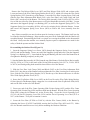
Disassembling the Stitcher Head (Figure 19)
Remove the 26/26D style Stitcher Head from
the stitcher machine. On 2601AHD, 2601DHD
and 2601EHD series heads, loosen the Bonnet
Clamp Eccentric Handle (9003A) and remove the
Stitcher Head from the Bonnet Clamp Block (9002).
On 2001DHD and 2301DHD series heads, loosen
and remove the Bonnet Stud Nut (HN1213) while
supporting the Head. Remove the Head from the
stitcher machine and place it on a clean work area.
Loosen, but do not remove, the Screws securing
the Face Plate Retaining Clips. With the Face Plate
Clips hanging loosely from the Bonnet, remove the
Face Plate paying special attention to the loose Wire
Cutters (9048). Remove the Wire Cutter Operating
Slide, the Wire Cutter Operating Slide Friction Plug,
22
9010
5160
9013BA-25*
9009-25 or
9009-21x25
Figure 18 - Replacing the Driver
* Parts shown in outline are separated for identification purposes only.
2651
2607
2608
2611
9022
2606
9025
2142A or
2627A
2137A or
2623A
9012A
9512A
9712A
9163
9075
9013BA
9056 (3)
UA2305.2 (3)
9034
9058
0084
LW8
2132ba
2146CA
9046a
2151A
9037
2152
9127
9032
2147
9043B
2154
9036A
9038A or
9038M
9048 (2)
2155A
Figure 19 - Disassembling the Head
the Wire Cutter Operating Slide Friction Spring and place these pieces along side of the Bonnet.
Release the Swivel (9038A or 9038M) from the Swivel Holder (2147 or 9043B) by lifting the Swivel
Operating Spring (2155A or 9046A) off of the Swivel. Continue to rotate the Spring upward until it
can be released from the Swivel Operating Lever Stud (2152 or 9127); until it is approximately at an
11 o’clock position. Remove the Swivel Operating Lever Hub (2154) from the Stud. The 26D style
Heads have a Screw (9058) securing the Stud to the Bonnet, thus securing the Hub to the Bonnet as
well. Remove this Screw in order to remove the Stud and Swivel Operating Lever (2151A). Remove
any accessories at this time in addition to the Swivel Holder.
23
Remove the Grip Release Slide Lever (9025) and Grip Release Slide (9022) and set them aside.
Loosen and remove the Wire Guide Spring Bracket Screw (9075), which will release the Wire Guide
Spring Bracket (2651) from the top of the Bonnet. Loosen the Face Plate Locating Screw (2608) and
slide the Face Plate Adjustment Slide Block (2611) or the Face Plate Lock Clamp (2606) and Lock
Block (2607) out the top of the Bonnet. The Driving Slide Assembly Link (2142A or 2627A) will be
free to slide out of the top of the Bonnet now as well as the Bender Bar Assembly (9013BA). Loosen
and remove the Supporter Spring Lever Bushing (9037) as well as the Supporter Spring (9032). The
Supporter Spring Lever Assembly (9036A) will now be swinging freely within the Bonnet. Loosen
and remove the Supporter Spring Lever Screw (9034) to remove the Lever Assembly from the
Bonnet.
Any of these assemblies can now be taken apart for cleaning or repair. The Bonnet itself can also
be cleaned or checked for damage. Most common wear parts can be exchanged while the Head is still
assembled though. Reassembling the Head is as simple as reversing the method used to disassemble
the Head. Always turn the machine over manually anytime repairs or adjustments are made for the
safety of both the operator and the Stitcher Head.
Re-assembling the Stitcher Head (Figure 19)
1. Insert the Supporter Spring Lever Screw (9034) through the Supporter Spring Lever Assembly
(9036A) and into the Bonnet. Grease one end of the Supporter Spring and insert it into the Supporter
Spring Lever Bushing (9037). Insert both the Spring and Bushing into the back of the Bonnet but do
not tighten the Bushing completely at this point.
2. Start the Bender Bar Assembly (9013BA) into the top of the Bonnet. Hook the Driver Bar Assembly
(9012A, 9512A or 9712A) in the notch of the Driving Slide Assembly Link (2137A, 2142A, 2623A
or 2627A) and finish guiding both assemblies between the rails of the Bonnet.
3. Slide the Face Plate Lock Clamp (2606) and Block (2607) or the Face Plate Adjustment Slide
Block (2611) into the top of the Bonnet but do not tighten the Face Plate Locating Screw at this point.
Next, slide the Wire Guide Spring Bracket (2651) into the top of the Bonnet and secure it with the
Wire Guide Spring Bracket Screw (9075).
4. Secure the Grip Release Slide Lever (9025) on the Pivot Pin on the Wire Guide Spring Bracket.
Oil the right rail of the Bonnet slightly, engage the Lever in the notch of the Grip Release Slide (9022)
and rest the Slide on the rail of the Bonnet.
5. Grease one end of the Wire Cutter Operating Slide Friction Spring (9051) and the Wire Cutter
Operating Slide Friction Plug (9050) and insert both into the Bonnet. Rest the Wire Cutter Operating
Slide (9049), along the left Bonnet rail, on the Friction Plug. Secure the Swivel Operating Lever
(2151A), the Swivel Operating Lever Hub (2154) and the Swivel Operating Lever Stud (2152 or
9127) to the Bonnet. Verify the orientation is correct.
6. Secure the Face Plate (2132BA or 2146CA), with the Wire Cutters (9048), to the Bonnet by
tightening the Screws (UA2305.2 and 0084) securing the Face Plate Clips (9056 and 9171). Make
sure the internal assemblies move freely before mounting the Head on a Machine.
24
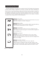
Troubleshooting (Figure 20)
The quality and quantity of work that can be produced with the 26/26D Stitcher Head is dependent
upon the operator making all adjustments as accurately as possible and carefully maintaining the
head. The cause of staple imperfections usually can be traced to inaccurate settings or normal wear
of moving parts. In the event of trouble of this nature occurring, the operator can, by referring to
the following troubleshooting chart, quickly locate and remedy the cause or causes of the trouble.
The following is a brief list of problems and solutions which should cover the majority of situations
encountered when stitching with the 26/26D Stitching Head.
problem:
Left Leg Short
Lengthen the left leg. (See page 14) Check the Grip for wear and
clean, rotate or replace it if needed. (See page 22)
solution:
problem:
Right Leg Short
Shorten the left leg to match the right leg, then adjust both legs
to desired length by adjusting the Face Plate. (See page 15)
solution:
problem:
Corner Buckled
Check the Driver (9009-wire size) for a chipped corner and
rotate or replace it if needed. (See page 22) Check the tensile strength of the
wire or use thicker wire.
solution:
problem:
Leg(s) Buckled
solution: If the ends of an unformed piece of wire are not smooth,
the Wire Cutters (9048) are worn. Check for wear and rotate or replace
if needed. (See page 20) Make sure the correct wire size is being used and
that the wire is straight.
problem:
Crown Bent or Buckled
solution: Check Supporter Spring (9032) tension, adjust the
Supporter Spring Lever Bushing or replace the Spring if needed. Check
for correct wire size being used. Check for correct work thickness setting.
Make sure there is not too much chamfer on the Swivel or that it is worn.
Figure 20 - Troubleshooting
25
problem:
Partially Formed Stitches
solution: Replace the worn Driver Bar Latch (9014) or Driver
Bar (9012A). The Grip Spring (9019) could be worn or broken, replace it.
problem:
Stitch in Pieces or Right or Left Leg Sheared Off
solution: Clean and lubricate Swivel (9038A or 9038M). (See page 19)
Loosen the Swivel Holder Screw and correct the alignment between the
Swivel Holder and the Bender Bar. If problem persists, file the forming
corner of the Swivel slightly with a honing stone.
problem:
Left Leg Missing
solution: Clean the Grip (9015). Reverse or replace the part if
needed. (See page 22) Make sure the Wire Straightener Rollers are not set
too tight. Make sure the Tension Pawl is not worn and is pivoting correctly.
(See page 21)
problem:
Corner of stitch broken or nearly cut through
solution: File the forming corner of the Swivel slightly with a honing
stone if too sharp. Lower Clincher Points (9083) if too high. (See page 16)
Loosen the Swivel Holder Screw and correct the alignment between the
Swivel Holder and the Bender Bar.
problem:
Corners of the Crown are Rounded
solution: Replace the worn Swivel (9038A or 9038M).
problem:
Loose Clinch
Check thickness setting for work or raise Clincher Points
(9083). (See page 17)
solution:
problem:
Legs are Spread or Contracted
Re-adjust the Wire Straightener Eccentrics to improve
straightness. (See page 13) Check the Wire Cutters for wear and
rotate or replace. (See page 20) Check the Bender Bar (9013BA-wire size)
for wear in the grooves and replace if necessary.
solution:
problem:
No wire being drawn
Lower the Face Plate. (See page 15)
solution:
Figure 20 - Troubleshooting
26
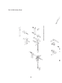
Bonnet Sub-Assembly - “D” Style
9056BA
9056N
9075
ua2305.2 (3)
2601B
9003a
9056 (3)
lw8
9056S
9058
9110
0084
9034
ua3812.4
9002
2151A
2154
HN1213
9171
9109
2156
2150
2157
2152
9050
9049
ua3806.1
9549
9749
2609
9044b (2)
2148A (2)
2624
9051
2147
9747
9847
9032
2155A
(ASSEMBLY5-1/2” LONG)
9036A
9037
9035
9038A
OR
9038M
(Magnetic
round wire
only)
9033
9081 (2)
9030 (2)
9079 (2)
9830 (2)
27
9047
(pin only)
The 26/26D Stitcher Head
28
29
Bonnet Sub-Assembly - “A” Style
9056BA
2390
9075
2388
9056N
2601R
ua2305.2 (3)
2601W
9056 (3)
9139 (2)
lw8
2389
9056S
9058
9110
9003a
ua3812.4
9002
9109
HN1213
9034
0084
9127
9171
2157
ua3806.1
9050
9163
9051
9049
9036A
2609
9032
2624
9046A
(ASSEMBLY4-1/2” LONG)
9044b
9043b
9047
(pin only)
9038A
OR
9038M
9037
9035
9033
5108
(Magnetic
round wire
only)
9042
5106
9081 (2)
9030 (2)
9038A
9079 (2)
5107
30
Face Plate Assembly
OLD 26 STYLE
(For 26d style)
2146CA
2146MA (with adjuster slot)
2546CA
9746BA
9144
(For 26a style)
2132ba
2532BA
9066
9103 (3)
9166
CA9166
9124 (4)
9068
9065
9070
9129B (2)
9069
9067
9130
9098
9134
* Complete Assembly Part
Numbers 2161 ("A" Style)
and 2162 ("D" Style) Include:
- Wire Straightener Eccentric
- Tension Pawl
- Tension Pawl Spring
- Wire Straightener Rollers
- Wire Straightener Roll Clips
- Wire Straightener Nut
- Wire Straightener Pointer
9048 (2)
31
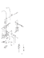
Driving Slide Assembly - “D” Style
For Bostitch 17-AW
and No. 17 Machines
9025B
(only on
"d" style)
2616
56
2651
1060
2629
9025
9097
2614
2607
2606
9022
2608
2612
9522
9722
2610
2611
2613
2602B
2215
For Machines without
Adjuster Rails
2143
2142A (1/2" [12 MM] CRANK)
2627A (1/2" [12 MM] RAIL)
2103B
Crank-Driven
Heads
2542A (3/8" [10 MM] CRANK)
2543A (3/8" [10 MM] RAIL)
2228
driving slide assemblies
9082
0035
2626B
9006
for crank
2144
32
for rail
Driving Slide Assembly - “A” Style
2651
driving slide assemblies
2616
9076
56
1060
9097
for crank
for rail
9077
CAA9074R
2607
Crank-Driven
Heads
For Machines without
Adjuster Rails
2215
2606
2608
2602
2103B
2614
9025
2228
2610
2137a (1/2" [12 MM] CRANK)
2623A (1/2" [12 MM] RAIL)
9164B
2537a (3/8" [10 MM] CRANK)
2523A (3/8" [10 MM] RAIL)
2611
9028
0035
2626B
9006
2613
2007
2144
2612
33
9022
9522
9722
Bender Bar Assembly
Complete Assemblies
A9013BA-XX
9113
9112
9013BA-xx
9013M-XX
9513BA-xx
9715A-xx
9813BA-xx
9115
9026A
A9013M-25
A9513BA-25
A9715A-25
9014
HS-1-583B
9015
9526A
9728A
9826A
9024
9020
9019
UB2111.2
9023
9029
9013CA-25
Complete Assembly
A9013CA-25
9012A
9512A
9712A
HS-1-584B
9012m
9915
9014EA
9024B
LW2
9509-xx
9708-xx
9809-xx
9914
9015D
9009-xx
2182
34
9146
9073A
35
9103 (2)
9070
9065
9124 (2)
9068
9123 (2)
2133A
9069
56
2651
2616
1060
9067
9097
G20298
2110B (6)
G20287
2133BA
G20293B
G20293
G20292
G20297
Wire Guide Bracket and Spring
Clincher Plate Assemblies
optional
9088
9083 (tHIN1)
9083A (thick2)
7024B (For M2 Only)
7257B (
"
)
9083C (flat wire)
9086JA
2091
9086 (thin1)
9086A (thick2)
2089 (thin3)
2089A (thick3)
7253A (for m2 only)
9084B
(thin or thick
2091B
9800B-SOLID CLINCHER
optional
CTT9086B(thin)
CTT9086F(thick)
G50710
UA4808.7
9093 (thin)
9093A (thick)
9087
CT9093R(thin)
CT9093S(thick)
optional
2095B (thin3)
2095C (thick3)
18182 (for m2 only)
1-1/32" [0.75mm] wide
2-1/16" [1.5mm] wide
3-For bostitch #2 or 2aw. also used on acme/champion, interlake/isp model a.
for older rosback
style 201 machines
36
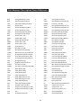
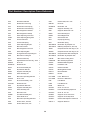
Part Number / Description Cross-Reference
0035
Driving Slide Spring - Heavy
1
2228
Driving Slide Pin Washer
1
0084
Solid Face Plate Clip Screw
1
2523A
Driving Slide Assembly 3/8 (Lug)
1
1060
Wire Guide Adjust Binder Screw
1
2532BA
Face Plate - 3/8 (26A)
1
18182
Clincher Slide
1
2537A
Driving Slide Assembly 3/8 (Link)
1
18183
Clincher Slide Adjusting Block
1
2542A
Driving Slide Assembly 3/8 (Link)
1
18184
Clincher Slide Block Clamp
1
2543A
Driving Slide Assembly 3/8 (Lug)
1
18186
Clincher Slide Adjusting Screw
1
2546CA
Face Plate Assembly 3/8 (26D)
1
2007
Driving Slide Spring Plunger
1
2601B
Bonnet Sub-Assembly (26D)
1
2089
Clincher Plate - Thin
1
2601R
Bonnet Sub-Assembly (26A)
1
2089A
Clincher Plate - Thick
1
2601W
Bonnet Sub-Assembly (Watkiss)
1
2091
Clincher Plate Binder Nut
2
2602
Driving Slide Lug (26A)
1
2095B
Clincher Slide - Thin
1
2602B
Driving Slide Lug (26D)
1
2095C
Clincher Slide - Thick
1
2606
Face Plate Locating Clamp
1
2103B
Driving Slide Pin
1
2607
Face Plate Lock Block
1
2132BA
Face Plate 1/2 (26A)
1
2608
Face Plate Lock Screw
1
2133A
Wire Guide Spring Assembly
1
2609
Bonnet Binder Stud
1
2133BA
Wire Guide Spring Asy w/ Oiler Felt
1
2609B
Bonnet Binder Stud (Metric)
1
2137A
Driving Slide Assembly Link (26A)
1
2610
Face Plate Adjust Slide
1
2142A
Driver Slide Assembly Link (26D)
1
2611
Face Plate Adjust Slide Block
1
2143
Driving Slide Swivel Operating Pin
1
2612
Face Plate Adjust Slide Stud
1
2144
Driving Slide Plunger
1
2613
Face Plate Adjust Slide Nut
1
2145
Supporter Guide Plate Screw
1
2614
Face Plate Adjust Slide Stud
1
2146CA
Face Plate 1/2 (26D)
1
2616
Wire Guide Spring Adjust Screw Stud 1
2146MA
Face Plate 1/2 w/Adjuster Slot (26D)
1
2623A
Driving Slide Assembly Link (26A)
1
2147
Swivel Holder (26D)
1
2624
Bonnet Stud Pin
1
2148A
Swivel Holder Clamp
2
2626B
Driving Slide Spring
1
2150
Swivel Holder Dowel
1
2627A
Driving Slide Assembly (26D)
1
2151A
Swivel Operating Lever
1
2629
Face Plate Adjustment Slide
1
2152
Swivel Operating Lever Stud
1
2651
Wire Guide Spring Bracket
1
2154
Swivel Operating Lever Hub
1
5037
Retaining Clip Rivet
1
2155A
Swivel Operating Spring
1
5160
Driver Release Pin
1
2156
Swivel Operating Spring Stud
1
56
Wire Guide Spring Bracket Screw
1
2157
Supporter Lever Lock Shoe
1
7024B
Clincher Point, Flat - 1/2
2
2161
Complete Face Plate Asy 1/2 (26A)
1
7253A
Clincher Plate - 1/2
1
2162
Complete Face Plate Asy 1/2 (26D)
1
7257B
Clincher Point, Round - 1/2
2
2182
Cap
1
9002
Bonnet Clamp Block
1
2215
Driving Shaft Connector
1
9003A
Bonnet Clamp Handle
1
37
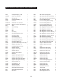
Part Number / Description Cross-Reference
9006
Driving Slide Spring - Light
1
9049
Wire Cutter Operating Slide
1
9009-XX
Driver - 1/2 - Wire Size
1
9050
Wire Cutter Oper Slide Friction Plug
1
9010
Retaining Clip
1
9051
Wire Cutter Oper Slide Friction Spring 1
9012A
Driver Bar Assembly - 1/2
1
9056
Face Plate Retaining Clip
3
9012M
Driver Bar
1
9056BA
Face Plate Clamp Block Assembly
1
9013BA-XX
Bender Bar - 1/2 - Wire Size
1
9056N
Face Plate Clamp Block Nut
1
9013CA-25
B/Bar Asy 1/2, External Grip Spring
1
9056S
Face Plate Clamp Block Screw
1
9014
Latch
1
9058
Swivel Operating Lever Screw
1
9014EA
Latch Assembly
1
9065
Wire Straightener Eccentric Roller
1
9015
Grip
1
9066
Wire Straightener Eccentric
1
9015D
Grip
1
9067
Wire Straightener Eccentric Nut
1
9019
Grip Spring
1
9068
Wire Straightener Eccentric Bushing
1
9020
Grip Spring Retaining Screw
1
9069
Wire Straightener Eccentric Spring
1
9022
Grip Release Slide
1
9070
Wire Straightener Eccentric Pointer
1
9023
Grip Retaining Clip
1
9073A
Wire Guide Spring Assembly
1
9024
Grip Retaining Clip Screw
1
9075
Wire Guide Spring Bracket Screw
1
9024B
Grip Spring Housing Screw
1
9076
Wire Guide Spring Brkt Adjust Screw 1
9025
Grip Release Slide Lever
1
9077
Wire Guide Spring Brkt Set Screw
1
9025B
Grip Release Slide Adjust. Lever Assy. 1
9078
Supporter Guide Plate Dowel
2
9026A
Supporter Assembly - 1/2
1
9079
Supporter Guide Plate Dowel
2
9028
Driving Slide Spring Lock Pin
1
9081
Screw
1
9029
Supporter Pivot Pin
1
9083
Clincher Point, Thin, Round
2
9030
Supporter Guide Plate
2
9083A
Clincher Point, Thick, Round
2
9032
Supporter Spring
1
9083C
Clincher Point, Thick, Flat
2
9032B
Supporter Spring - Heavy
1
9083-21
Clincher Point, Thin, Flat
2
9033
Dowel Pin
1
9084B
Adjustable Clincher Slide
1
9034
Supporter Spring Lever Screw
1
9086
Clincher Plate, Thin
1
9035
Supporter Spring Lever Roll
1
9086A
Clincher Plate, Thick
1
9036A
Supporter Spring Lever Assembly
1
9086JA
Clincher Plate, Thick
1
9037
Supporter Spring Lever Bushing
1
9087
Clincher Slide Adjusting Screw
1
9038A
Swivel Assembly - 1/2
1
9088
Clincher Plate Binder Bolt
2
9038M
Swivel Magnetic - 1/2
1
9093
Clincher Slide, Thin
1
9043B
Swivel Holder (26A)
1
9093A
Clincher Slide, Thick
1
9044B
Swivel Holder Screw
2
9097
Grip Release Lever Pin
1
9046A
Swivel Operating Spring (26A)
1
9098
Tension Pawl
1
9047
Swivel Operating Spring Pin
1
9103
Wire Straightener Roller
3
9048
Wire Cutter
2
9109
Bonnet Alignment Screw
1
38
Part Number / Description Cross-Reference
9110
Bonnet Screw Binder
1
9793
Clincher Slide, Thin - 5/16
1
9112
Bender Bar Friction Plug
1
9809-XX
Driver 5/8
1
9113
Bender Bar Friction Spring
1
9813BA-XX
Bender Bar - 5/8
1
9115
Bender Bar Friction Bushing
1
9826A
Supporter Assembly - 5/8
1
9123
Wire Straightener Roll Stud
3
9830
Supporter Guide Plate - 5/8
2
9124
Wire Straightener Roll Clip
4
9838A
Swivel Assembly 5/8
1
9127
Swivel Operating Lever Stud
1
9838M
Swivel Magnetic 5/8
1
9129B
Swivel Operating Spring Stud
1
9847
Swivel Holder 5/8
1
9130
Tension Pawl Rivet
1
9914
Grip Spring Housing
1
9134
Tension Pawl Spring
1
9915
Bender Bar Spring
1
9139
Swivel Operating Stop Pin
2
A9013BA-XX
Bender Bar Asy Complete 1/2
1
9144C
Wire Cutter Holder
1
A9013CA-25
B/Bar Asy Complete 1/2, Ext. Grip
1
9146
Wire Straightener Eccentric
1
A9086
Complete Clincher Plate Asy, Tn, Rd
1
9163
Swivel Operating Hub
1
A9086A
Complete Clincher Plate Asy, Tk, Rd
1
9164B
Driving Slide Swivel Operating Pin
1
A9513BA-25
Complete Bender Bar Assembly 3/8
1
9166
Wire Cutter Locating Pin
1
A9715BA-25
Bender Bar Asy Complete 5/16
1
9171
Solid Face Plate Clip
1
CA9166
Wire Cutter Locating Screw
1
9193A
Adjustable Clincher Plate Asy - Thick
1
CAA9074R
Wire Guide Spring Bracket
1
9509-XX
Driver 3/8
1
G50102
Bolt Mount Mounting Block
1
9513BA-XX
Bender Bar 3/8
1
G50394
Flat Washer - M8
4
9512A
Driver Bar Assembly 3/8
1
G50710
Clincher Plate Nut
2
9522
Grip Release Slide 3/8
1
G50716
Mounting Block Handle
1
9526A
Supporter Assembly 3/8
1
HN1213
Bonnet Stud Nut
1
9538A
Swivel Assembly 3/8
1
HN3816
Hex Nut
1
9549
Wire Cutter Operating Slide 3/8
1
HS-1-583B
Latch - McCain S.S.
1
9708-XX
Driver - 5/16
1
HS-1-584B
Driver Bar - McCain S.S.
1
9712A
Driver Bar Assembly - 5/16
1
LW8
Lock Washer
1
9715A-XX
Bender Bar 5/16
1
LW38
Lock Washer 3/8
1
9722
Grip Release Slide 5/16
1
PW38
Washer 3/8
1
9728A
Supporter Assembly 5/16
1
UA1428.1
Screw 1/4 - 28 x 1/4
1
9737A
Swivel Assembly 5/16
1
UA2305.2
Face Plate Retaining Clip Screw
3
9745
Wire Cutter 5/16
2
UA3216.4
Screw 10 - 32 x 7/8
2
9746BA
Face Plate Assembly 5/16
1
UA3806.1
Supporter Lever Lock Screw
1
9747
Swivel Holder 5/16
1
UA3812.4
Supporter Lever Stop Screw
1
9749
Wire Cutter Operating Slide 5/16
1
UA4808.7
Clincher Slide Adjuster Lock Screw
1
9783
Clincher Point, Thin 5/16
2
UB2111.2
Supporter Guide Pin
1
9786A
Clincher Plate, Thin, 5/16
1
39
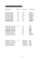
Variable Crown and Wire Sizes
Description Crown Wire Size Part Number
25
21x25
25
21x25
25
23
21
21x25
25
21
9715A-25
9715A-2125
9513BA-25
9513BA-2125
9013BA-25
9013BA-23
9013BA-21
9013BA-2125
9813BA-25
9813BA-21
Clincher Plate - Thin (1/32”)
55/16
Clincher Plate - Thin (1/32”)
Clincher Plate - Thick (1/16”) 3/8
Clincher Plate - Thick (1/16”) 3/8
Clincher Plate - Thick (1/16”) 3/8
Clincher Plate - Thin (1/32”) 1/2
Clincher Plate - Thick (1/16”) 1/2
Clincher Plate - M-Series 1/2
Clincher Plate - Thin (1/32”)
1/2
Clincher Plate - Thick (1/16”) 1/2
All
All
All
All
All
All
All
All
All
All
9786A
9086
9086A
9086JA
9800B
2089
2089A
7253A
CTT9086B
CTT9086F
Clincher Point - Thin (1/32”) 5/16
Clincher Point - Thin (1/32”) 3/8
Clincher Point - Thick (1/16”) 3/8
Clincher Point - Thick (1/16”) 3/8
Clincher Point - M-Series 1/2
Clincher Point - M-Series 1/2
Rd Wire Only
Rd Wire Only
Rd Wire Only
Flat Wire Only
Flat Wire Only
Rd Wire Only
9783
9083
9083A
9083C
7024B
7257B
Bender Bar Assembly
Bender Bar Assembly
Bender Bar Assembly
Bender Bar Assembly
Bender Bar Assembly
Bender Bar Assembly
Bender Bar Assembly
Bender Bar Assembly
Bender Bar Assembly
Bender Bar Assembly
5/16
5/16
3/8
3/8
1/2
1/2
1/2
1/2
5/8
5/8
40
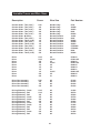
Variable Crown and Wire Sizes
Description Crown Clincher Slide - Thin (1/32”)
Clincher Slide - Thin (1/32”)
Clincher Slide - Thin (1/16”)
Clincher Slide - Thin (1/32”)
Clincher Slide - Thin (1/16”)
Clincher Slide - M-Series
Clincher Slide - Thin (1/32”)
Clincher Slide - Thick (1/16”)
Clincher Slide - Thin (1/32”)
Clincher Slide - Thick (1/16”)
Clincher Slide - Thin (1/32”)
Clincher Slide - Thick (1/16”)
Clincher Slide - Thin (1/32”)
Clincher Slide - Thick (1/16”)
Wire Size Part Number
5/16
3/8
3/8
3/8
3/8
1/2
1/2
1/2
1/2
1/2
1/2
1/2
5/8
5/8
Rd Wire Only
Rd Wire Only
Rd Wire Only
Rd Wire Only
Rd Wire Only
Rd and Flat Wire
Rd and Flat Wire
Rd and Flat Wire
Rd and Flat Wire
Rd and Flat Wire
Rd and Flat Wire
Rd and Flat Wire
Rd and Flat Wire
Rd and Flat Wire
9793
2095B
2095C
9093
9093A
18182
9093
9093A
2095B
2095C
CT9093R
CT9093S
9093
9093A
Driver
Driver
Driver
Driver
Driver
Driver
Driver
Driver
Driver
Driver
5/16
5/16
3/8
3/8
1/2
1/2
1/2
1/2
5/8
5/8
25
21x25
25
21x25
25
23
21
21x25
25
21
9708-25
9708-2125
9509-25
9509-2125
9009-25
9009-23
9009-21
9009-2125
9809-25
9809-21
Driver Bar Assembly
Driver Bar Assembly
Driver Bar Assembly
Driver Bar Assembly
5/16
3/8
1/2
5/8
All
All
All
All
9712A
9512A
9012A
9012A
All
All
All
All
All
All
All
All
All
All
All
All
2142A
2627A
2523A
2537A
2542A
2543A
2137A
2142A
2623A
2627A
2142A
2627A
Driving Slide Asy - Crank
Driving Slide Asy - Rail
Driving Slide Asy - Rail
Driving Slide Asy - Crank
Driving Slide Asy - Crank
Driving Slide Asy - Rail
Driving Slide Asy - Crank
Driving Slide Asy - Crank
Driving Slide Asy - Rail
Driving Slide Asy - Rail
Driving Slide Asy - Crank
Driving Slide Asy - Rail
5/16
5/16
3/8
3/8
3/8
3/8
1/2
1/2
1/2
1/2
5/8
5/8
41
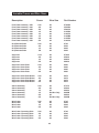
Variable Crown and Wire Sizes
Description Wire Size Part Number
Face Plate Assembly - 26D
5/16
Face Plate Assembly - 26A 3/8
Face Plate Assembly - 26D
3/8
Face Plate Assembly - 26A 1/2
Face Plate Assembly - 26D
1/2
Face Plate Assembly - 26D
1/2
Face Plate Assembly - 26A 5/8
Face Plate Assembly - 26D
5/8
All
All
All
All
All
All
All
All
9746BA
2532BA
2546CA
2132BA
2146CA
2146MA
2132BA
2146CA
Grip Release Slide
5/16
Grip Release Slide
3/8
Grip Release Slide
1/2
Grip Release Slide 5/8
All
All
All
All
9722
9522
9022
9022
Supporter
Supporter
Supporter
Supporter
5/16
3/8
1/2
5/8
All
All
All
All
9728A
9526A
9026A
9826A
5/16
3/8
1/2
5/8
All
All
All
All
9030
9030
9030
9830
Supporter Guide Plate Dowel 5/16
Supporter Guide Plate Dowel 3/8
Supporter Guide Plate Dowel 1/2
Supporter Guide Plate Dowel 5/8
All
All
All
All
9078
9078
9078
9079
Swivel Assembly
5/16
Swivel Assembly
3/8
Swivel Assembly
1/2
Swivel Assembly
1/2
Swivel Assembly
5/8
Swivel Assembly 5/8
All
All
All
Rd Wire Only
All
Rd Wire Only
9737A
9538A
9038A
9038M
9838A
9838M
Wire Cutter
Wire Cutter
Wire Cutter
Wire Cutter
5/16
3/8
1/2
5/8
All
All
All
All
9745
9048
9048
9048
Wire Cutter Operating Slide
Wire Cutter Operating Slide
Wire Cutter Operating Slide
Wire Cutter Operating Slide
5/16
3/8
1/2
5/8
All
All
All
All
9749
9549
9049
9049
Supporter Guide Plate
Supporter Guide Plate
Supporter Guide Plate
Supporter Guide Plate
Crown 42
( Type/Quantity Purchased )
Dealer Phone :
Country :
City : Dealer Street Address :
Dealer Name :
Date Received :
State/Province :
Zip :
de luxe STITCHER graphic arts representative
Serial Number(s) :
Head(s) Purchased :
Serial Number(s) :
With Head(s) :
Serial Number(s) :
Machine(s) Purchased :
product
Please take a moment to fill out the attached card and
mail it to DeLuxe Stitcher Company, Inc.
In addition, duplicate the information for your records
to assist when making further inquiries.
( First )
State/Province :
Zip :
E-mail :
Zip :
( Last )
Would you like information sent to you about new products
that would benefit your company?
Yes
No
Other Bindery Products Used :
Dealer Phone :
Country :
City : Fax : ( Type/Quantity Purchased )
Dealer Street Address :
Dealer Name :
Date Received :
Serial Number(s) :
Head(s) Purchased :
Serial Number(s) :
With Head(s) :
Serial Number(s) :
( Middle Initial )
State/Province : Machine(s) Purchased :
Phone : Country :
City : Street Address :
Company :
Name :
To better service your wire stitching needs, please
take a moment to fill out and return this registration card.
registration
customer
p ro d u c t
d e a l e r
Driver Bar Assembly
Latch
Grip Grip Spring
Grip Spring Retaining Screw
Grip Retaining Clip
Grip Retaining Clip Screw
Swivel Assembly
Wire Cutter
Wire Cutter Oper. Slide Friction Plug
Wire Cutter Slide Friction Spring
Clincher Points-Thin
Clincher Points-Thick
Tension Pawl
Wire Straightener Roller
Bender Bar Friction Plug
Bender Bar Friction Spring
Wire Straightener Roll Clip
Tension Pawl Spring
9134
9124
9113B
9112
9103
9098
9083A
9083
9051
9050
9048
9038M
9024
9023
9020
9019
9015
9014
9012A
9009-25
parts
* You can purchase the 26DRPK which includes these and other common replacement
Driver
Item Number
Description Below is a list of the most common wear/replacement parts for the
26/26D Stitcher Head. This guide should help you when ordering
replacement parts. If the part you need is not listed below, please
refer to the more detailed parts list on pages 38-40 in this manual.
Common Replacement Parts for 1/2” Crown
COMPANY INC .
6635 West Irving Park Road
Chicago, Illinois 60634-2410 U.S.A.
Attn: Customer Service
DeLuxe Stitcher
here
stamp
place
LIMITED WARRANTY
DeLuxe Stitcher Company warrants to the original retail purchaser
that this product is free from defects in material and workmanship and
agrees to repair or replace, at DeLuxe Stitcher’s option, any defective
product within 90 days from the date of purchase. This warranty is not
transferable. It covers damage resulting only from defects in material or
workmanship and does not cover conditions or malfunctions resulting from
normal wear, neglect, abuse or accident.
This warranty is in lieu of all other express warranties. Any warranty of
merchantability or fitness for a particular purpose is limited to the duration
of this warranty. DeLuxe Stitcher shall not be liable for any incidental or
consequential damages.
Some states do not allow limitations on how long an implied warranty lasts,
or the exclusion or limitation of incidental or consequential damages, so
the above limitations or exclusions may not apply to you. This warranty
gives you specific legal rights and you may also have other rights which
vary from state to state.
To obtain warranty service you must return the product, at your expense,
together with proof of purchase to an authorized DeLuxe Stitcher
Graphic Arts Dealer.
Always use genuine DeLuxe Stitcher parts. When ordering parts, please identify the
part number, the part name, the wire size and crown size of your Stitcher.
DeLuxe Stitcher Company, Inc.
6635 West Irving Park Road
Chicago, Illinois 60634-2410
Phone: 773-777-6500 800-634-0810
Fax: 773-777-0156 800-417-9251
E-mail: [email protected]
Web Site: http://www.deluxestitcher.com
45
DBS26D-1008