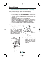
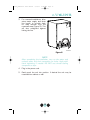
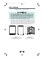
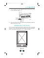
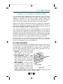
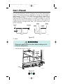
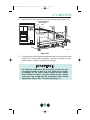
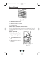
1
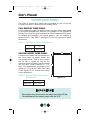
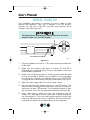
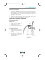
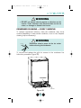
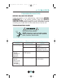
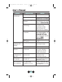
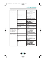
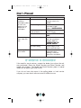
30005_CLRCO2075_UM_Cover.qxd
8/22/03
4:27 PM
Page 1
É c h e l o n™
P. O .
B o x
2 4 5 0 4 0
Milwaukee, WI 53224-9540
Phone: 414.354.0300
Fax:
414.354.7905
w w w . u - l i n e . c o m
U
S
E
R
M
P r i n t e d
i n
U . S . A .
P / N
3 0 0 0 5
( R e v.
0 8 / 0 3 )
A
N
U
A
L
30005_CLRCO2075_UM_Cover.qxd
8/22/03
4:27 PM
Page 2
U-LINE CORPORATION LIMITED WARRANTY
U-Line Corporation warrants each U-Line product to be free from defects in materials and
workmanship for a period of one year from the date of purchase; and warrants the sealed
system (consisting of the compressor, the condenser, the evaporator, the hot gas bypass
valve, the dryer and the connecting tubing) in each U-Line product to be free from defects
in materials and workmanship for a period of five years from the date of purchase. During
the initial one-year warranty period for all U-Line products U-Line shall: (1) at U-Line’s
option, repair any product or replace any part of a product that breaches this warranty; and
(2) for all Marine, RV and Domestic U-Line products sold and serviced in the United States
(including Alaska and Hawaii)and Canada, U-Line shall cover the labor costs incurred in
connection with the replacement of any defective part. During years two through five of the
warranty period for the sealed system, U-Line shall:. (1) repair or replace any part of the
sealed system that breaches this warranty; and (2) for all Marine, RV and Domestic U-Line
products sold and serviced in the United States (including Alaska and Hawaii)and Canada,
U-Line shall cover the labor costs incurred in connection with the replacement of any defective part of the sealed system. All other charges, including transportation charges for
replacements under this warranty and labor costs not specifically covered by this warranty, shall be borne by you. This warranty is extended only to the original purchaser of the
U-Line product. The Registration Card included with the product should be promptly
completed by you and mailed back to U-Line or you can register on-line at
www.U-LineService.com.
The following are excluded from this limited warranty: installation charges; damages
caused by disasters or acts of God, such as fire, floods, wind and lightening; damages
incurred or resulting from shipping, improper installation, unauthorized modification, or misuse/abuse of the product; customer education calls; food loss/spoilage; door and water
level adjustments (except during the first 90 days from the date of purchase); defrosting the
product; adjusting the controls; door reversal; or cleaning the condenser.
If a product defect is discovered during the applicable warranty period, you must promptly
notify either the dealer from whom you purchased the product or U-Line at P.O. Box 23220,
Milwaukee, Wisconsin 53223 or at 414-354-0300. In no event shall such notification be
received later than 30 days after the expiration of the applicable warranty period. U-Line
may require that defective parts be returned, at your expense, to U-Line’s factory in
Milwaukee, Wisconsin, for inspection. Any action by you for breach of warranty must be
commenced within one year after the expiration of the applicable warranty period.
This limited warranty is in lieu of any other warranty, express or implied, including,
but not limited to any implied warranty of merchantability or fitness for a particular
purpose; provided however, that to the extent required by law, implied warranties are
included but do not extend beyond the duration of the express warranty first set
forth above. U-Line’s sole liability and your exclusive remedy under this warranty is
set forth in the initial paragraph above. U-Line shall have no liability whatsoever for
any incidental, consequential or special damages arising from the sale, use or installation of the product or from any other cause whatsoever, whether based on warranty (express or implied) or otherwise based on contract, tort or any other theory
of liability.
Some states do not allow limitations on how long an implied warranty lasts or the exclusion
or limitation of incidental or consequential damages, so the above limitations may not apply
to you. This warranty gives you specific legal rights, and you may also have other rights
which vary from state to state.
30005_CLRCO2075 User Manual
8/22/03
4:23 PM
Page 1
INTRODUCTION
Congratulations on your purchase of U-Line CLRCO2075 Combination
Ice Maker/Refrigerator. A pioneer in the field for nearly 40 years,
U-Line is the world’s number one manufacturer of built-in, undercounter ice making and specialty refrigeration products. U-Line dedicates 100% of its research and development to these products. The
result: U-Line technology leads the market with innovation, design,
depth of product line and performance.
U-Line also backs customers with a strong dealer network. U-Line’s
commitment to quality even extends to environmentally safe packaging.
U-Line products are making life more convenient in homes, businesses,
and hotels around the world.
PLEASE READ all instructions completely before attempting
to install or operate the unit. All models of Ice Makers and
Combos require a connection to the water supply. Improper
hook-up can result in substantial property damage! If you are
unsure of your ability to safely connect the water
supply to the unit, consult a licensed plumber for assistance.
Once you have your unit installed, we suggest you keep this manual in
a safe place for future reference. Should any problems occur, refer to
the TROUBLESHOOTING section of this manual. This information will
help you quickly identify a problem and get it remedied. In the event you
require assistance, please contact the dealer where you purchased
your unit.
PLEASE RECORD YOUR MODEL’S INFORMATION
Whenever you call to request information or service, you will need to
know your model number and serial number. You can find this information on the serial plate located on the inside wall of your unit and on
the product registration card.
PRODUCT REGISTRATION CARD
The package containing this manual also includes your product
registration information. Warranty coverage begins at the time your
unit was purchased.
NOTE
Complete and mail the Product Registration Card as soon
as possible to validate the registration date. You may also
register the product online at www.U-LineService.com.
1
30005_CLRCO2075 User Manual
8/22/03
5:07 PM
Page 2
User’s Manual
If you do not return your Product Registration Card, U-Line will use the
date of sale to the U-Line distributor as the first date of warranty for
your unit. Please also record the purchase date of your
U-Line unit and your dealer’s name, address and telephone number.
Model Number:
________________________________________
Serial Number:
________________________________________
Purchase Date:
________________________________________
Dealer Name:
________________________________________
Dealer Address:
________________________________________
Dealer Telephone:
________________________________________
Keep this manual and the sales receipt together in a safe place for further reference.
TABLE OF CONTENTS
INTRODUCTION..........................................................................1
SAFETY PRECAUTIONS ...............................................................3
PRODUCT DIMENSIONS ..............................................................5
DRAIN INSTALLATION .................................................................5
CONNECTING A DRAIN PUMP .....................................................8
SITE PREPARATION ....................................................................9
BUILT-IN INSTALLATION.............................................................11
CONNECTING THE WATER SUPPLY ............................................12
LEVELING THE UNIT .................................................................14
REVERSING THE DOOR .............................................................15
DOOR ADJUSTMENT ................................................................18
CUSTOM DOOR PANELS ...........................................................20
INITIAL START-UP.....................................................................22
CLEAR ICE MAKER OPERATION..................................................25
PERIODIC CLEANING AND USER MAINTENANCE .........................30
DEFROSTING ...........................................................................36
STORAGE, VACATION AND MOVING ...........................................37
TROUBLESHOOTING .................................................................39
IF SERVICE IS REQUIRED ...........................................................42
2
30005_CLRCO2075 User Manual
8/22/03
4:24 PM
Page 3
SAFETY PRECAUTIONS
Do not attempt to install or operate your unit until you have read the
safety precautions in this manual. Safety items throughout this manual
are labeled with a Danger, Warning or Caution based on the risk type.
DEFINITIONS
!
This is the safety alert symbol. It is used to alert you to
potential personal injury hazards. Obey all safety messages
that follow this symbol to avoid possible injury or death.
! DANGER !
DANGER indicates an imminently hazardous situation
which, if not avoided, will result in death or serious injury.
! WARNING
WARNING indicates a potentially hazardous situation
which, if not avoided, could result in death or serious injury.
! CAUTION
CAUTION indicates a potentially hazardous situation which,
if not avoided, may result in minor or moderate injury.
CAUTION
CAUTION used without the safety alert symbol indicates a
potentially hazardous situation which, if not avoided, may
result in property damage.
Indicates installation, operation or maintenance information
which is important but not hazard-related.
3
30005_CLRCO2075 User Manual
8/22/03
4:24 PM
Page 4
User’s Manual
GENERAL PRECAUTIONS
! DANGER !
RISK OF CHILD ENTRAPMENT. Before you throw away your
old refrigerator or freezer, take off the doors and leave
shelves in place so that children may not easily climb inside.
! WARNING
• Never attempt to repair or perform maintenance on the
unit until the electricity has been disconnected.
• Altering, cutting of power cord, removal of power cord,
removal of power plug, or direct wiring can cause serious
injury, fire and/or loss of property and/or life and will
void the warranty.
CAUTION
• Do not lift unit by door handle.
• Use care when moving the unit. Some edges are sharp
and may cause personal injury. Wear gloves when moving or positioning the unit.
• Never install the unit behind closed doors. Be sure front
grille is free of obstruction. Obstructing free air flow can
cause the unit to malfunction, and may void the warranty.
• Allow unit temperature to stabilize for 24 hours before use.
• Never use an ice pick or other sharp instrument to help
speed up defrosting. These instruments can puncture
the inner lining or damage cooling unit.
• Failure to clean the condenser every three months can
cause the unit to malfunction. This could void the
warranty.
CAUTION
• DO NOT use any type of heater to defrost. Using a heater
to speed up defrosting can cause damage to the inner
lining.
• Use only genuine U-Line replacement parts. Imitation
parts can damage the unit, and may void the
warranty.
4
30005_CLRCO2075 User Manual
8/22/03
4:24 PM
Page 5
PRODUCT DIMENSIONS
24"
(61)
23-15/16"
(60.8)
34-1/8"
(86.7)
FULL
RETRACT
HEIGHT
WATER
CONNECTION
WATER
VALVE
21-3/4"
(55.2)
WATER
DRAIN
CLRCO001
Figure 1
DRAIN INSTALLATION
PLEASE READ all instructions completely before attempting
to install or operate the unit. All Ice Makers require a connection to the water supply and improper hook-up can
result in substantial property damage! All water and drain
connections MUST BE made by a licensed/qualified plumbing contractor. Failure to follow recommendations and
instructions may result in damage and/or harm.
CAUTION
Plumbing installation must observe all state and local
codes. All water and drain connections MUST BE made by
a licensed/qualified plumbing contractor. Failure to follow
recommendations and instructions may result in damage
and/or harm.
5
30005_CLRCO2075 User Manual
8/22/03
4:24 PM
Page 6
User’s Manual
The CLRCO2075 can be installed using a gravity drain or can use a
factory installed or equivalent drain pump.
Follow these guidelines when installing drain lines to prevent water from
flowing back into the ice maker storage bin and/or potentially flowing
onto the floor causing water damage:
Gravity Drain
• Drain lines must have a 5/8 inch inside diameter.
• Drain lines must have a 1 inch drop per 48 inches of run (1/4 inch
per foot) and must not create traps.
• The floor drain must be large enough to accommodate drainage
from all drains.
• Insulate the bin drain line to prevent condensation.
CLRCO2075 With Factory Installed Drain Pump
NOTE
Before installing your U-Line CLRCO2075 With Factory
Installed Pump, it is extremely important to check and test
all hose connections at the drain pump. There is a
possibility that hose connections may have loosened during
shipment.
! WARNING
To prevent accidental electrocution, make certain that the
floor surfaces surrounding the unit are dry whenever power
is removed from, or applied to the unit.
1.
2.
Make certain the unit is not plugged into an electrical outlet.
Carefully push the power cord grommet (Figure 2) through the
hole in the back panel.
WATER
DRAIN
Figure 2
6
CLRCO002
30005_CLRCO2075 User Manual
8/22/03
4:24 PM
Page 7
3.
Remove screws securing back panel.
4.
Check that the clamps and hose connections (Figure 3) are tight at
the following areas:
• Discharge tube (A)
• Drain tube (B)
• Vent tube (C)
B
B
C
A
BACK VIEW
SIDE VIEW
CLRCO003
Figure 3
5.
Place a suitable container beneath the pump’s discharge tube.
(The bucket must be able to hold a minimum of one gallon.)
! WARNING
Back panel serves as a guard. DO NOT remove the back
panel unless it is to be serviced or procedure requires it to
be removed. It must be in place during normal operation.
Failure to follow this warning could result in serious
personal injury or death.
6.
Plug the ice maker power cord into a properly grounded, polarized
electrical outlet.
7.
Verify pump operation by pouring one gallon of water into the ice
storage bin of the ice maker. The pump should energize and pump
the water into the container.
8.
At this time, verify that all tube and clamp connections are tight
and leak free.
9.
Unplug unit power cord from electrical outlet.
10. Leave back panel off for water supply line installation.
11. Continue to the next step in the installation process, SITE
PREPARATION.
7
30005_CLRCO2075 User Manual
8/22/03
4:24 PM
Page 8
User’s Manual
CONNECTING A DRAIN PUMP
If a gravity drain connection is not available, and you have not
purchased the CLRCO2075 with factory installed pump, we strongly recommend the use of the U-Line P60 drain pump. The U-Line
P60 drain pump is available through your Dealer, or direct from U-Line
with complete installation instructions. If a pump other than the U-Line
P60 drain pump is to be used, it must meet the following specifications:
• It must be UL listed and have a UL listed, 120 VAC, 3-wire
grounded power cord.
• It must have overall maximum outside dimensions of 8-3/4" wide x
5-3/4" deep x 7-3/4" high.
• It must have a minimum flow rate of 15 gallons per hour at 10 feet
of lift.
• It must have a sealed sump which does not allow water leakage in
the case of a power outage, restricted drain or pump failure.
• It must have a check valve in the discharge line to prevent waste
water return to the pump.
• It must have an overflow protection control which will shut off power
to the ice maker in the event of a pump failure.
• It must have an operating temperature range of 50°F to 110°F
(10°C to 40°C).
CAUTION
In the event of a power outage, restricted drain or pump
failure, the failure to use the U-Line P60 drain pump or a
pump with the above listed specifications, could result in
substantial water leakage and pooling with severe and
costly water damage and related consequential damages
and harm.
8
30005_CLRCO2075 User Manual
8/22/03
4:24 PM
Page 9
SITE PREPARATION
1.
Position the unit on a flat, level surface, capable of supporting the
entire weight of the unit. Remember that the unit will be significantly heavier once it is fully loaded.
It is extremely important that the unit is level. If it is not
level, the water will not flow over the ice mold evenly. This
can cause a reduction in ice rate, uneven sized cubes or
water spilling into the storage area which will cause the ice
in the bin to melt prematurely. Remember that floors near
drains have a tendency to slope towards the drain.
2.
The surrounding air temperature must be at least 50°F (10°C) but
must not exceed 110°F (40°C).
3.
The unit must not be located near heat-generating equipment or in
direct sunlight.
4.
The unit must be located to allow clearance for water, drain and
electrical connections in the rear of the ice maker.
5.
Connect the unit to a grounded and polarized 115 VAC, 60 Hz,
15A circuit (normal household current).
! DANGER !
ELECTROCUTION HAZARD!
Electrical Grounding Required. This appliance
is equipped with a three prong (grounding)
polarized plug for your protection against
possible shock hazards.
• NEVER remove the round grounding prong from the plug.
• NEVER use a two-prong grounding adapter.
• NEVER use an extension cord to connect power to the
unit.
Where a two-prong wall receptacle is encountered or a
longer power cord is required, contact a qualified electrician
to have it replaced in accordance with applicable electrical
codes.
9
30005_CLRCO2075 User Manual
8/22/03
4:24 PM
Page 10
User’s Manual
NOTE
All U-Line units have a zero
clearance for the door to
open (Figure 4). See BUILTIN INSTALLATION for additional clearance requirements.
CABINET
OR WALL
DOOR
SWING
0"
CLEARANCE
NEEDED
NOTE
Stainless Steel models
require a minimum of
2-1/2" door handle clearance when installed against
a wall.
UL124A
Figure 4
Install and connect the water supply line. See CONNECTING THE
WATER SUPPLY for installation requirements.
7.
Position the unit to allow free air flow through the front grille
(Figure 5).
C
L
N
O
F
F
O
N
6.
EXHAUST
INTAKE
CLRCO004
Figure 5
8.
Wipe out inside of unit with a clean, water-dampened cloth.
10
30005_CLRCO2075 User Manual
8/22/03
4:24 PM
Page 11
BUILT-IN INSTALLATION
Your U-Line product has been designed for either free-standing or builtin installation. When built-in, your U-Line product does not require additional air space for top, sides or rear. However, the front grille must
NOT be obstructed.
CAUTION
Do not install unit behind closed doors.
Table 3. Built-in Cabinet Dimensions
A
Unit Dimensions
B
C
34-1/8"
23-15/16"
24"
NOTE
To ease unit installation and removal, it is recommended
that the cabinet rough opening dimensions be increased by
at least 1/4" over the dimensions given for your unit. The
unit must be located to allow clearance for water, drain and
electrical connections in the rear of the ice maker.
B
A
C
CLRCO002a
11
30005_CLRCO2075 User Manual
8/22/03
4:24 PM
Page 12
User’s Manual
CONNECTING THE WATER SUPPLY
When connecting the water supply, follow these guidelines:
• Review the local plumbing codes before you install the unit.
• In most instances, the cold water supply will come from the
basement through a hole in the floor.
• The water pressure should be between 20 minimum and 120
maximum psi.
• Install a shut-off valve in the 1/4 inch supply line.
• Connect sufficient tubing to the unit to allow the unit to be
moved for cleaning and servicing. However, make certain that
the tubing is not pinched or damaged during installation.
• U-Line recommends the use of copper tubing for installation.
1.
Locate the compression
fitting and ferrule packed in
the unit. Slide the compression fitting and ferrule over
the 1/4 inch water supply
line. Do not use thread
sealing compound or tape.
Using two wrenches, tighten
the compression fitting on
the supply line (Figure 6).
UL134
Figure 6
WATER
SOLENOID VALVE
2.
HOSE
CONNECTOR
WATER SUPPLY LINE
CLRCO013
Figure 7
12
Carefully bend the water
supply line into position and
connect the line to the
water solenoid valve (Figure
7). Avoid kinking the water
supply line.
30005_CLRCO2075 User Manual
3.
8/22/03
4:24 PM
Page 13
For recessed installations, allow
extra water supply and drain
line length to provide slack
for easy removal from the
recessed area (Figure 8). This
will also safeguard against
kinking the line.
CLRCO005
Figure 8
NOTE
After completing the installation, turn on the water and
recheck water and drain connection for leaks. Apply additional tightening if needed. DO NOT use thread sealing
compound or tape.
4.
Plug in the power cord.
5.
Gently push the unit into position. If desired the unit may be
recessed into cabinet or wall.
13
30005_CLRCO2075 User Manual
8/22/03
4:24 PM
Page 14
User’s Manual
LEVELING THE UNIT
It is extremely important that the unit is level. If it is not
level, the water will not flow over the ice mold evenly. This
can cause a reduction in ice rate, uneven sized cubes or
water spilling into the storage area which will cause the ice
in the bin to melt prematurely. Remember that floors near
drains have a tendency to slope towards the drain.
1.
Use a level to check the levelness of the ice maker from front to
back and from side to side for free-standing installation (Figure 9).
Use a level to check the levelness of the icemaker from front to
back and from side to side by placing a level on the inside edge and
along the door seal edge for built-in installation (Figure 10).
FRONT
CLRCO029
SIDE
CLRCO006
Figure 9
(Free-Standing Installation)
Figure 10
(Built-In Installation)
14
30005_CLRCO2075 User Manual
2.
8/22/03
4:24 PM
Page 15
If the ice maker is not level, adjust the feet on the corners of the
unit as necessary (Figure 11).
RAISE
LOWER
DWR005
Figure 11
3.
Check the levelness after each adjustment and repeat the previous
steps until the unit is level.
REVERSING THE DOOR
All U-Line units (except Stainless Steel models) may be left or right hand
opening. The door opening is easily reversed by moving the hinge hardware to the opposite side (Figure 12). To reverse the door:
UL318B
Figure 12
15
30005_CLRCO2075 User Manual
8/22/03
4:24 PM
Page 16
User’s Manual
1. Remove top hinge screw pin
(7/64" Allen wrench) from
cabinet (Figure 13). Remove
door by tilting forward and
lifting off bottom hinge pin.
3. Remove top hinge (3 screws),
reinstall hinge screw pin, and
remount on opposite side
BOTTOM (Figure 15).
HINGE
SCREW
PIN
UL313
Figure 15
UL310
Figure 13
2. Remove plastic screw plugs
(3 each, top and bottom)
from new hinge location. Do
not discard (Figure 14).
4. Remove the two door closers
from the existing bottom hinge
and install as shown on the
new bottom hinge location
(Figure 16).
SCREW
PLUGS
DOOR
CLOSERS
BOSS
UL308
UL312
Figure 16
Figure 14
16
30005_CLRCO2075 User Manual
8/22/03
4:24 PM
Page 17
5.
Remove existing bottom hinge (3 screws) and remount on
opposite side TOP. Remove hinge screw pin.
6.
With bottom of door facing up, remove pivot plate (2 screws), flip
over, and remount on opposite side of door (Figure 17).
UL319
Figure 17
7.
Holding door upright with top of
door tilted forward, place hole of
door pivot plate on bottom hinge
screw pin (Figure 18). Be sure
that the bosses on the closers
align with holes in hinge and hinge
plate.
8.
Tilt top of door into position in top
hinge and install top hinge screw
pin.
9.
Install plastic screw plugs
removed in Step 2 in old hinge
holes (3 each, top and bottom).
BOSS
CLRCO008
Figure 18
17
30005_CLRCO2075 User Manual
8/22/03
4:24 PM
Page 18
User’s Manual
DOOR ADJUSTMENT
Your door is aligned at the factory before shipment. Occasional
re-adjustment may be necessary, especially if an Overlay Panel is
installed. The following procedure will correct for up to 1/4" alignment.
The door should never be flush with the top of the cabinet.
Even when level, the top edge of the door will be 1/8" below
the top of the cabinet (Figure 19).
To adjust :
1.
Compare the top edge of
the door (opposite the
hinges) to the top edge of
the cabinet and note the
type (up or down) of
adjustment needed.
2.
Remove the top hinge
pivot pin with a 7/64" hex
wrench (Figure 20) and lift
door off bottom hinge pin.
Be careful not to lose door
closers (Figure 22).
1/8"
DOOR001
Figure 19
3. With door upside-down, loosen
but do not remove the two hinge
plate screws.
UL310
Figure 20
18
30005_CLRCO2075 User Manual
4.
8/22/03
4:24 PM
Page 19
If door edge opposite the hinges needs to move up, move plate
toward outside of door. If door edge needs to move down, move
plate toward inside of door (Figure 21). Repeat until top edge of
door is parallel with top of cabinet and tighten screws securely.
SLOTTED
MOUNTING
HOLES
NOTCH
RAISE
OUTSIDE
DOOR EDGE
LOWER
OUTSIDE
DOOR EDGE
CLRCO001a
Figure 21
5. After adjustment is complete,
remove the door closers from
the
bottom
hinge,
clean
thoroughly and apply petroleum
jelly to the mating surfaces of
the closers (Figure 22). Be
sure that bosses on closers
align with holes in hinge and
hinge plate. Mount door and
install top hinge pivot pin.
DOOR
CLOSERS
BOSS
UL312
Figure 22
19
30005_CLRCO2075 User Manual
8/22/03
4:24 PM
Page 20
User’s Manual
CUSTOM DOOR PANELS
Two types of custom door panels can be installed on your U-Line unit
to harmonize with or accent the surrounding decor.
FULL OVERLAY DOOR PANEL
A full overlay door panel completely covers the door frame and handle
to give a built-in appearance. See your U-Line dealer for the optional Full
Overlay Door Panel Kit which contains the Panel Preparation Document
for building and installing a full overlay panel or visit our website at
www.u-line.com. See Table 1 and Figure 23 for full overlay door panel
dimensions.
Table 1. Full Overlay Panel Dimensions
A
B
29-7/8"
23-3/4"
CUSTOM INSERT DOOR PANEL
B
A custom door panel can be inserted into
the door frame to better match the
surrounding decor. Custom door panels
can be flat or raised, as long as the
maximum panel thickness where inserted
into the door reveal (channel) is 1/4" A
thick. For raised panels, the depth of the
reveal is 1/4" on all four sides. See Table
2 and Figure 23 for custom door panel
insert dimensions.
Table 2. Custom Insert Door Panel
Dimensions
A
28-5/32"
Figure 23
B
23-1/32"
The custom door panels must not weigh more than 20 lbs.
The thickness of the custom panel must be 3/4".
20
30005_CLRCO2075 User Manual
8/22/03
4:24 PM
Page 21
Install the insert as follows:
! WARNING
Insert edges may be
SHARP! Use care when
installing.
1.
Remove top hinge screw pin
(7/64" Allen wrench, Figure 24).
Remove door by tilting forward
and lifting off bottom hinge pin.
2.
Pull door gasket out of groove
(top edge of door only). Start in
the middle and pull outward, moving toward the edge (Figure 25).
This may take some force. Do not
remove the three screws behind
gasket.
3.
Remove two outside screws
holding door handle. Slightly separate door handle from door
(Figure 26).
4.
Pull handle up and off. Remove
outer door panel and cardboard
spacer.
5.
Slide custom door panel insert into
1/4 inch channel in door front.
6.
Holding door gasket out of the
way, replace handle on door
making sure it is seated properly
on insert and that screw holes
line up.
7.
Install two small screws removed
in step 3.
8.
Starting at the corners and
working inward, push door gasket
into place on door.
9.
Place door on bottom hinge pin
and install upper hinge screw.
21
UL310
Figure 24
DWR020
Figure 25
UL132
Figure 26
30005_CLRCO2075 User Manual
8/22/03
4:24 PM
Page 22
User’s Manual
INITIAL START-UP
Once installation and leveling is complete, the unit is ready for initial
start-up and operation. Your unit is shipped in the ON position,
however, you may turn it ON/OFF using the cycle selector switch
located in the grille (Figure 27).
C
L
N
O
F
F
O
N
C
L
N
O
F
F
O
N
The temperature controller will display even when the cycle
selector switch is in the OFF position.
CYCLE SELECTOR SWITCH
UL316C
Figure 27
1.
Plug the appliance cord into a 115V polarized and grounded electrical outlet.
2.
Make sure the overflow tube (refer to Figures 37 and 38 in
Maintenance) is seated properly. There is a possibility it may have
loosened during shipment.
3.
Make sure the draining system is working properly and the drain
hose is not pinched or kinked. Pour one gallon of cool, fresh water
into the ice bin. The water should drain freely. If your CLRCO2075
is equipped with a drain pump, the pump should drain the ice bin.
4.
Open the water supply valve in the main water source.
5.
Be sure that the cycle selector switch is in the ON position. The
water fill valve will energize and fill the water reservoir. The water fill
valve shuts off after 180 seconds. The compressor begins to operate and water flows over the evaporator assembly (ice cube tray).
6.
Upon initial start-up, water flow over the evaporator may be
uneven. This may cause uneven sized cubes or water spilling into
the ice storage bin. This is a normal situation and will correct itself
within the first twenty-four hours of operation. After the initial startup period, the water will cascade evenly over the evaporator.
22
30005_CLRCO2075 User Manual
8/22/03
4:24 PM
Page 23
After the first slab of ice is produced, ice production will stop until the
refrigerator side of the CLRCO2075 reaches the set point temperature. After the refrigerator reaches temperature, ice production will
begin again.
It is possible that dirt or scale will dislodge in the water line.
Always throw away all ice cubes made during the first two
to three hours of operation.
TEMPERATURE CONTROLLER
1
2
3
WARMER
SET
TEMP
COOLER
CLRCO011
Figure 28
The temperature controller (Figure 28) is located below the clear ice
maker. It consists of an LED display, three LED status indicator lights
and three touchpad buttons. The LED display shows the temperature
set point and is calibrated in degrees Fahrenheit. The controller is factory programmed for a set point of 38°F which will show when the unit
is first powered up.
To display actual temperature in the refrigerator, press the “WARMER”
button momentarily. A solid status indicator light (1, Figure 28) will
show and the air temperature reading in the cabinet will show for
approximately 10 seconds.
To adjust the temperature set point, press the “SET TEMP” button
momentarily; the display will flash. Press the “WARMER” or “COOLER”
button as desired to change the set point. When the desired set point
shows on the display, wait 10 seconds and the new set point will be
saved. Wait 24 hours for the temperature to stabilize before checking
the actual temperature again.
23
30005_CLRCO2075 User Manual
8/22/03
4:24 PM
Page 24
User’s Manual
Refer to Table 1 to determine indicator light status.
LED
1
2
Status
• Solid
• Flashing
• Solid
3
• Flashing
• Solid
• Flashing
Indicates
• Refrigerator Temperature displayed
• Not Applicable
• Service Menu – wait 10 seconds and
it will exit automatically
• Open Thermistor – call for service
• Service Menu – wait 10 seconds and
it will exit automatically
• Drain Pump Blocked – check
installation and drain line. Call for
service.
Table 1. Indicator Light Status
24
30005_CLRCO2075 User Manual
8/22/03
4:24 PM
Page 25
CLEAR ICE MAKER OPERATION
The ice maker side is designed to make clear ice from most water
sources on a consistent basis. Water is constantly circulated over the
evaporator assembly. As the water freezes, gravity causes any
sediment to drop into the water trough and not become imbedded in
the ice. This gives a clearer ice cube with a low mineral content.
When the ice reaches the desired thickness, it falls off the evaporator
and into the storage bin. The cycle is then repeated until the ice bin is
full and then stops automatically. As the ice level in the bin drops the
unit will automatically restart to keep the bin full.
Your unit’s ice production rate may vary depending on many considerations. Ambient air temperatures, water temperatures, a high level of
opening and closing, loading the refrigerator with warm items, condenser
cleanliness and ice-maker cleanliness are all contributing factors to how
quickly the unit produces ice. The refrigerator portion of the CLRCO2075
will take precedence over producing ice to protect any perishables.
Certain sounds are normal during the unit’s operation. You may hear
the compressor or fan motor, the water valve, the water circulation
pump or ice dropping into the ice storage bin.
ICE CUBE THICKNESS
Your U-Line Clear Ice Maker uses advanced technology to make ice that
is crystal clear. This technology cascades a flow of water over a chilled
ice mold that is mounted vertically so no water sits in it. Because of
this ice making technology, clear ice cubes differ significantly from regular ice cubes. Differences are as follows:
• Dimples. U-Line clear ice cubes
have “dimples” on one side from
the cascading water process.
• Cube Variations. Cubes made
DIMPLES
from different batches, or even
cubes within the same batch may
have varying dimples, thicknesses
and/or sizes due to the cascading
water process.
• Cube “slabbing”. The U-Line clear
ice maker makes a “slab” of ice
ICE BRIDGE
that falls from the vertical mold
ICE001
relying on gravity to break the ice
Figure 29
bridges. Depending on the control
setting, and the fullness of the ice bucket, it maybe necessary to tap
the ice slab with the ice scoop to break it apart.
25
30005_CLRCO2075 User Manual
8/22/03
4:24 PM
Page 26
User’s Manual
The ice cube thickness control is factory set for best overall performance. The factory setting is designed to maintain an ice bridge of
approximately 1/16" to 1/8" under normal conditions resulting in a
dimple of approximately 1/4" to 1/2" in depth (Figure 30). A fuller
cube with less of a dimple results in a thicker ice bridge. As the ice
bridge becomes thicker, the tendency for the cubes to stay together as
a slab increases. A bridge thicker than 1/8" may cause cubes to overfill the ice bucket.
1/16" TO 1/8"
ICE BRIDGE
1/4" TO 1/2"
DIMPLE
BRIDGE
TOO THICK
BRIDGE
TOO THIN
LITTLE OR
NO DIMPLE
DIMPLE
TOO DEEP
GOOD
BAD
ICE002
Figure 30
To adjust:
! WARNING
Disconnect power to the ice maker before making any ice
thickness adjustments.
1.
Disconnect power to the unit.
ACCESS
PANEL
SCREWS
WARMER
SET
TEMP
COLDER
CLRCO030
Figure 31
26
30005_CLRCO2075 User Manual
2.
8/22/03
4:24 PM
Page 27
Remove the screws securing the front access panel (Figure 31).
ICE CUBE THICKNESS
ADJUSTMENT
DIAL
-2
-5
-3
-4
-1 0 1
3
4
5
2
DIAL IS FACTORY
SET TO “0”
CLRCO031
Figure 32
3.
Locate the ice cube thickness adjustment dial on the control board
(Figure 32). Turn the dial clockwise (+ number) to thicken or counterclockwise (- number) to thin the ice bridge.
Ice thickness adjustment dial should be turned only one
increment (number on dial) at a time. Allow the ice maker
to stabilize for 24 hours before making further adjustments. Since ice cubes in any given batch will vary, choose
cubes from the sample area for comparison when making
adjustments (Figure 33). The factory setting is +1.
27
30005_CLRCO2075 User Manual
8/22/03
4:24 PM
Page 28
User’s Manual
SAMPLE AREA
ICE005
Figure 33
4.
Reinstall front access cover.
5.
Reconnect power to ice maker.
6.
Empty ice bucket.
GLASS SHELF REMOVAL/INSTALLATION
On units with right-hand hinges, open door fully, grasp shelf firmly, lift
front edge slightly and pull straight out. On units with left-hand hinges,
refer below.
Removal (Figure 34)
1.
Pull shelf out about 6" until
back of shelf clears the
“hump” on the right hand
side.
1
3
2
2.
Tilt right hand edge of shelf
up.
3.
Remove shelf from unit by
pulling out.
CLRCO009A
Figure 34
28
30005_CLRCO2075 User Manual
8/22/03
4:24 PM
Page 29
Adjustment/Installation
1.
To move to a different position in the unit, insert shelf at an angle,
approximately 15-20°, over the rib in the side of the unit where you
want to place the shelf. The shelf must be started into the unit at
an angle to clear the door.
2.
Continue to slide the shelf into the unit at an angle until it clears
the door. Lower the shelf and rest it on the rib.
DOOR SHELF REMOVAL/INSERTION
To Remove Door Shelf
(Figure 35):
1.
Grasp shelf in center, lift
slightly, and tilt 15°-20°.
2.
Carefully pull shelf off bosses.
NOTCH
To Install Door Shelf:
1.
Holding shelf in center, align
notches in shelf with bosses
in door.
2.
Tilt shelf at a 15°-20° angle
and slide onto bosses at the
desired location.
BOSS
CLRCO010
Figure 35
29
30005_CLRCO2075 User Manual
8/22/03
4:24 PM
Page 30
User’s Manual
PERIODIC CLEANING AND
USER MAINTENANCE
Periodic cleaning and proper maintenance will ensure efficiency, top
performance, and long life. The maintenance intervals listed are based
on normal conditions. You may want to shorten the intervals if you have
pets, the unit is used outdoors, or other special considerations.
EXTERIOR CLEANING — AS REQUIRED
The door, grille and cabinet may be cleaned with a mild detergent and
warm water solution. Do not use solvent based or abrasive cleaners.
Use a soft sponge and rinse with clean water. Wipe with a soft, clean
towel to prevent water spotting.
Stainless steel models can discolor when exposed to chlorine gas and
should be cleaned. Clean stainless steel models with a mild detergent
and warm water solution and a damp cloth. Never use abrasive cleaning agents.
CAUTION
Stainless steel models exposed to chlorine gas and moisture, such as areas with spas or swimming pools, may have
some discoloration of the stainless steel. Discoloration
from chlorine gas is normal.
INTERIOR CLEANING — AS REQUIRED
1.
Turn cycle selector switch to OFF.
2.
Open the door and remove shelves if desired. Refer to GLASS
SHELF REMOVAL/INSTALLATION.
3.
Remove any ice from the storage bin.
4.
Wipe down the interior and storage bin with a solution of nonabrasive mild soap or detergent and warm water. Rinse with
clean water.
5.
Sanitize the bin with a solution of 1 tablespoon of bleach in 1
gallon of warm water. Rinse thoroughly with clean water.
6.
Turn cycle selector switch to ON.
7.
Repeat the steps in Initial START-UP to check the draining system.
30
30005_CLRCO2075 User Manual
8/22/03
4:24 PM
Page 31
! WARNING
• DO NOT use solvent cleaning agents or abrasives on the
interior. These cleansers may transmit taste to the ice
cubes, or damage or discolor the interior.
CONDENSER CLEANING — EVERY 3 MONTHS
To maintain operational efficiency, clean the condenser every three
months (depending on environment conditions, more or less frequent
cleaning may be necessary).
! WARNING
Disconnect electric power to the ice maker
before cleaning the condenser.
To remove and replace the grille for access to the condenser fins
follow this procedure (Figure 36):
CONDENSER
CLRCO014
Figure 36
31
30005_CLRCO2075 User Manual
8/22/03
4:24 PM
Page 32
User’s Manual
1.
Remove the screws at each end of the grille.
2.
Remove the grille.
! WARNING
DO NOT touch the condenser fins. The condenser fins are
SHARP and can be easily damaged.
CAUTION
DO NOT use any type of cleaner on the condenser unit.
3.
Clean the condenser coil using a soft brush with a “combing” action
or vacuum cleaner. Do not touch the condenser coil.
4.
Position the grille to align the screw holes with the cabinet.
5.
Insert the grille screws and tighten. Do not overtighten.
SELF CLEANING CYCLE — EVERY 6 MONTHS
To maintain operational efficiency, clean the unit every six months
(depending on water conditions, more or less frequent cleaning may be
necessary). If the ice maker requires more frequent cleaning, consult
a qualified plumber to test the water quality and recommend appropriate treatment.
! WARNING
Wear rubber gloves and safety goggles and/or
face shield when handling Ice Machine Cleaner.
CAUTION
Use only U-Line Ice Machine Cleaner (part number 41978).
It is a violation of Federal law to use this solution in a manner inconsistent with its labeling. Use of any other cleaner
can ruin the finish of the evaporator and will void the warranty. Read and understand all labels printed on the package before use.
32
30005_CLRCO2075 User Manual
8/22/03
4:24 PM
Page 33
Ice machine cleaner is used to remove lime scale and other mineral
deposits. Refer to the following steps for mineral deposit removal.
The refrigerator side does not operate during the ice maker
cleaning cycle. Remove all fresh food to prevent spoilage.
CAUTION
Never use anything to force ice from the evaporator.
Damage may result.
Always remove perishables before
cleaning.
1.
Set the cycle selector switch
to OFF and allow the ice to
melt off of the evaporator.
2.
Remove all ice from the
storage bin.
3.
Remove inside front cover
(Figure 37).
4.
Remove the overflow tube
by lifting it up while using
a slight back and forth
motion to loosen it from the
drain hole (Figure 38). The
water in the reservoir will
flow down the drain.
5.
Replace the overflow tube
after all of the water has
drained from the reservoir.
6.
Move the cycle selector
switch to the CLN position.
7.
When water begins to flow
over the evaporator (approximately 3 minutes), add
one package of U-Line Ice
Machine cleaner to the
water reservoir.
8.
FRONT COVER
UL208
Figure 37
OVERFLOW
CLRCO012
Figure 38
Reinstall inside front cover.
33
30005_CLRCO2075 User Manual
8/22/03
4:24 PM
Page 34
User’s Manual
9.
When the self-cleaning process stops (approximately 45 minutes),
clean the storage bin.
10. Wipe down the interior and storage bin with a solution of nonabrasive mild soap or detergent and warm water. Rinse with
clean water.
11. Sanitize the bin with a solution of 1 tablespoon of bleach in 1
gallon of warm water. Rinse thoroughly with clean water.
12. Move the cycle selector switch to the ON position to resume ice
production.
Repeat the steps in Initial START-UP to check the draining system
and discard the first ice harvest.
NOTE
Ice production after the first harvest may take longer
after Self Cleaning Cycle since the refrigeration portion
will take precedence over producing ice to protect any
perishables. Once the refrigerator reaches a set temperature, ice making will resume to normal.
34
30005_CLRCO2075 User Manual
8/22/03
4:24 PM
Page 35
INLET SCREEN CLEANING — EVERY YEAR
The solenoid valve inlet screen must be cleaned at least once each year
as follows:
1.
Shut off the water at the water supply valve.
2.
Pull the unit out to access the back panel.
3.
Disconnect electrical power to
the unit.
4.
Disconnect the hose connector
from the water solenoid
valve (Figure 39).
5.
Use a tooth brush to clean
sediment from the inlet
screen. DO NOT remove the
screen.
6.
Re-connect the water supply
line to the water solenoid
valve.
Tighten
connector
securely. Open the water
supply valve and check for
leakage at the water connection. Make sure the water
supply line is not kinked.
WATER
SOLENOID VALVE
HOSE
CONNECTOR
WATER SUPPLY LINE
CLRCO013
Figure 39
7.
Reconnect power to the unit before re-installing.
8.
Make sure the drain system is working properly and the drain hose
is not pinched or kinked. Pour one gallon of cool, fresh water into
the ice bin. The water should drain freely. If your CLRCO2075 is
equipped with a drain pump, the pump should drain the ice bin.
35
30005_CLRCO2075 User Manual
8/22/03
4:24 PM
Page 36
User’s Manual
LIGHT BULB REPLACEMENT
Light bulb replacement
Échelon™ series is simple.
1.
2.
in
the
Remove the light housing cover
by sliding the cover toward the
tab, swinging the end opposite
the tab down and pulling down
and away (Figure 40).
Replace bulb with genuine U-Line
#31317 replacement.
1
TAB
2
U-Line P/N 31317
3.
UL305
3
Figure 40
Replace the light housing cover by inserting the tab FIRST, sliding
the cover toward the tab and pushing up the other end. You should
hear a snap/click.
DEFROSTING
NOTE
Cycle defrost models do not normally require manual
defrosting. However, in extremely high humidity or during
periods of unusually high usage, minimal manual defrosting
may be required.
36
30005_CLRCO2075 User Manual
8/22/03
4:24 PM
Page 37
STORAGE, VACATION AND MOVING
If the unit is to be stored, moved or not used for extended periods, it
will be necessary to drain the system of water.
! WARNING
Electrical Shock Hazard. Disconnect power
before servicing. Before operating replace all
panels. Failure to do so can result in death or
electrical shock.
1.
Disconnect power from the unit.
2.
Remove ice from the storage bin.
3.
Shut off water supply at the main water source.
4.
Disconnect the inlet and outlet lines and allow them to drain.
! WARNING
If the ambient temperature is expected to drop below 40°F,
drain all water from the unit to prevent freezing damage not
covered by the warranty.
NOTE
The use of anti-freeze or other products of this nature is not
necessary and is not recommended.
5.
Disconnect inlet and outlet lines to the water valve.
6.
Drain water from the water trough and drain line by removing the
overflow tube (Figure 41).
37
30005_CLRCO2075 User Manual
8/22/03
4:24 PM
Page 38
User’s Manual
FRONT COVER
OVERFLOW
CLRCO012
UL208
Figure 41
7.
Clean the ice maker and storage bin before next use.
8.
Prop door open to allow for air circulation and prevent mold and
mildew.
It is possible that dirt or scale will dislodge in the water line.
Always throw away all ice cubes made during the first 24
hours of operation when the unit is returned to
service.
38
30005_CLRCO2075 User Manual
8/22/03
4:24 PM
Page 39
TROUBLESHOOTING
BEFORE CALLING FOR SERVICE
If the unit appears to be malfunctioning, read through NORMAL
OPERATION first. If the problem persists, check the TROUBLESHOOTING GUIDE. Locate the problem in the guide and refer to the
cause and its remedy before calling for service. The problem could be
something very simple which can be solved without a service call.
TROUBLESHOOTING GUIDE
! DANGER !
ELECTROCUTION HAZARD
NEVER attempt to repair or perform maintenance on the unit until the main electrical
power has been disconnected.
Troubleshooting — What to check when problems occur
Problem
No interior light.
Possible Cause
No power to unit.
Loose or burned out bulb.
Unit does not
operate.
Temperature
Controller
displaying.
Unit does not
operate.
Switch is ON.
Temperature
Controller
not displaying.
Cycle Selector Switch
in OFF position.
No electrical supply.
39
Remedy
Make sure power cord is
plugged in.
Tighten or replace bulb.
See page 36 for light
replacement instructions.
Turn switch to ON.
Plug unit in or check
circuit breaker.
30005_CLRCO2075 User Manual
8/22/03
4:24 PM
Page 40
User’s Manual
Problem
The unit is not
cold enough.
Possible Cause
Light staying on.
Remedy
Call for service.
Dirty condenser coils.
Clean condenser. Refer to
CONDENSER CLEANING.
Airflow must not be
obstructed to front grille.
Refer to INSTALLATION.
Use the temperature
controller to set
temperature colder.
Allow 24 hours for
temperature to stabilize.
Make sure no obstructions
are blocking the door and
unit is level. Refer to
LEVELING THE UNIT.
Door adjustment required.
Refer to DOOR
ADJUSTMENT.
Turn Cycle Selector Switch
to ON.
Check installation and
drain line for kinks.
Airflow to front grille
blocked.
Temperature not set
cold enough.
Door is not closing
completely.
Temperature
controller LED
flashing.
Noise during
operation.
Cycle Selector Switch in
OFF position.
Drain pump blocked.
Unit malfunction.
Certain sounds
are normal.
Fresh food section
on Combo units
too cold.
The unit does
not operate.
Temperature control
set too cold.
Low air temperature
around unit.
Unit runs but no
ice is produced.
No water being
supplied to the unit.
40
Call for service.
Soft sounds from the fan
and water/dropping
sounds from the ice
maker will be heard.
Use the temperature
controller to set
temperature warmer.
Surrounding air
temperature must be at
least 50°F (10°C).
Check to see that water
is connected and turned
on to the unit.
30005_CLRCO2075 User Manual
Problem
Unit runs but
produces very
little ice.
8/22/03
4:24 PM
Page 41
Possible Cause
Dirty condenser coils.
High air temperature
around unit.
Scale and mineral
buildup in unit.
Inadequate airflow at
the front of the unit.
Cleaning Cycle recently
performed.
Ice is slow to
release or does
not release from
the evaporator.
Ice-making system
is dirty.
Poor ice quality.
(soft or unclear)
Unit is not level.
Poor incoming water
quality.
Ice-making system is
dirty.
41
Remedy
Clean the condenser.
Refer to PERIODIC
CLEANING AND USER
MAINTENANCE.
Surrounding air
temperature of over
90°F (32°C). Low ice
production at high
temperatures is normal.
Clean unit. Refer to
PERIODIC CLEANING
AND USER
MAINTENANCE.
Remove items blocking
airflow.
Allow unit to reach the set
temperature to produce ice
normally.
Run unit through
automatic clean cycle.
Refer to PERIODIC
CLEANING AND
USER MAINTENANCE.
Refer to LEVELING THE
UNIT.
Consult a qualified
plumber to test the
water quality and
recommend appropriate
treatment.
Run unit through
automatic clean cycle.
Refer to PERIODIC
CLEANING AND
USER MAINTENANCE.
30005_CLRCO2075 User Manual
8/22/03
4:24 PM
Page 42
User’s Manual
Problem
Unit produces
shallow or
incomplete cubes,
or the ice fill
pattern on the
evaporator is
incomplete.
Possible Cause
Low water level.
Water leaking
from under the
unit.
Supply line leaking.
Hot incoming water.
Incorrect incoming
water pressure.
Unit is not level.
Bin drain leaking.
Ice storage bin
full of water.
Obstructed drain.
Remedy
Check to see that
overflow tube is fully
seated.
Connect the unit to a
cold water supply.
Refer to INSTALLATION.
Water pressure must
be 20-120 psi.
Refer to LEVELING THE
UNIT.
Check to see that water
inlet line is attached
properly. Refer to
CONNECTING THE
WATER SUPPLY.
Check integrity of bin
drain hose and clamp.
Check to see that
storage bin drain
opening is free from
obstruction and debris.
IF SERVICE IS REQUIRED
If the need for service arises, contact the dealer from whom the unit
was purchased. State the Model Number and Serial Number and
explain the problem. The Model and Serial Number plate is located
inside unit at upper right hand corner.
If you do not know the name of the selling dealer or local service
company, you can check online at www.U-LineService.com
42
30005_CLRCO2075 User Manual
8/22/03
4:24 PM
43
Page 43
30005_CLRCO2075 User Manual
8/22/03
4:24 PM
User’s Manual
44
Page 44
30005_CLRCO2075_UM_Cover.qxd
8/22/03
4:27 PM
Page 2
U-LINE CORPORATION LIMITED WARRANTY
U-Line Corporation warrants each U-Line product to be free from defects in materials and
workmanship for a period of one year from the date of purchase; and warrants the sealed
system (consisting of the compressor, the condenser, the evaporator, the hot gas bypass
valve, the dryer and the connecting tubing) in each U-Line product to be free from defects
in materials and workmanship for a period of five years from the date of purchase. During
the initial one-year warranty period for all U-Line products U-Line shall: (1) at U-Line’s
option, repair any product or replace any part of a product that breaches this warranty; and
(2) for all Marine, RV and Domestic U-Line products sold and serviced in the United States
(including Alaska and Hawaii)and Canada, U-Line shall cover the labor costs incurred in
connection with the replacement of any defective part. During years two through five of the
warranty period for the sealed system, U-Line shall:. (1) repair or replace any part of the
sealed system that breaches this warranty; and (2) for all Marine, RV and Domestic U-Line
products sold and serviced in the United States (including Alaska and Hawaii)and Canada,
U-Line shall cover the labor costs incurred in connection with the replacement of any defective part of the sealed system. All other charges, including transportation charges for
replacements under this warranty and labor costs not specifically covered by this warranty, shall be borne by you. This warranty is extended only to the original purchaser of the
U-Line product. The Registration Card included with the product should be promptly
completed by you and mailed back to U-Line or you can register on-line at
www.U-LineService.com.
The following are excluded from this limited warranty: installation charges; damages
caused by disasters or acts of God, such as fire, floods, wind and lightening; damages
incurred or resulting from shipping, improper installation, unauthorized modification, or misuse/abuse of the product; customer education calls; food loss/spoilage; door and water
level adjustments (except during the first 90 days from the date of purchase); defrosting the
product; adjusting the controls; door reversal; or cleaning the condenser.
If a product defect is discovered during the applicable warranty period, you must promptly
notify either the dealer from whom you purchased the product or U-Line at P.O. Box 23220,
Milwaukee, Wisconsin 53223 or at 414-354-0300. In no event shall such notification be
received later than 30 days after the expiration of the applicable warranty period. U-Line
may require that defective parts be returned, at your expense, to U-Line’s factory in
Milwaukee, Wisconsin, for inspection. Any action by you for breach of warranty must be
commenced within one year after the expiration of the applicable warranty period.
This limited warranty is in lieu of any other warranty, express or implied, including,
but not limited to any implied warranty of merchantability or fitness for a particular
purpose; provided however, that to the extent required by law, implied warranties are
included but do not extend beyond the duration of the express warranty first set
forth above. U-Line’s sole liability and your exclusive remedy under this warranty is
set forth in the initial paragraph above. U-Line shall have no liability whatsoever for
any incidental, consequential or special damages arising from the sale, use or installation of the product or from any other cause whatsoever, whether based on warranty (express or implied) or otherwise based on contract, tort or any other theory
of liability.
Some states do not allow limitations on how long an implied warranty lasts or the exclusion
or limitation of incidental or consequential damages, so the above limitations may not apply
to you. This warranty gives you specific legal rights, and you may also have other rights
which vary from state to state.
30005_CLRCO2075_UM_Cover.qxd
8/22/03
4:27 PM
Page 1
É c h e l o n™
P. O .
B o x
2 4 5 0 4 0
Milwaukee, WI 53224-9540
Phone: 414.354.0300
Fax:
414.354.7905
w w w . u - l i n e . c o m
U
S
E
R
M
P r i n t e d
i n
U . S . A .
P / N
3 0 0 0 5
( R e v.
0 8 / 0 3 )
A
N
U
A
L