1
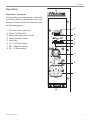
BM6 mkIII – Owner’s manual Introduction Introduction Important safety instructions The lightning flash with an arrowhead symbol within an equilateral triangle, is intended to alert the user to the presence of uninsulated “dangerous voltage” within the product’s enclosure that may be of sufficient magnitude to constitute a risk of electric shock to persons. The exclamation point within an equilateral triangle is intended to alert the user to the presence of important operating and maintenance (servicing) instructions in the literature accompanying the product. 1.Read these instructions. 2.Keep these instructions. 3.Heed all warnings. 4.Follow all instructions. 5.Do not use this apparatus near water. 6.Clean only with dry cloth. 7.Install in accordance with the manufacturer’s instructions. 8.Do not install near any heat sources such as radiators, heat registers, stoves, or other apparatus (including amplifiers) that produce heat. 9.Do not defeat the safety purpose of the polarized or grounding-type plug. A polarized plug has two blades with one wider than the other. A grounding type plug has two blades and a third grounding prong. The wide blade or the third prong are provided for your safety. If the provided plug does not fit into your outlet, consult an electrician for replacement of the obsolete outlet. 10. Protect the power cord from being walked on or pinched particularly at plugs, convenience receptacles, and the point where they exit from the apparatus. 11.Only use attachments/accessories spe cified by the manufacturer. 12.Use only with the cart, stand, tripod, bracket, or table specified by the manufacturer, or sold with the apparatus. When a cart is used, use caution when moving the cart/apparatus combination to avoid injury from tipover. 13.Unplug this apparatus during lightning storms or when unused for long periods of time. 14.Refer all servicing to qualified service personnel. Servicing is required when the apparatus has been damaged in any way, such as power-supply cord or plug is damaged, liquid has been spilled or objects have fallen into the apparatus, the apparatus has been exposed to rain or moisture, does not operate normally, or has been dropped. Warning! –To reduce the risk of fire or electrical shock, do not expose this equipment to dripping or splashing and ensure that no objects filled with liquids, such as vases, are placed on the equipment. –This apparatus must be earthed. –Use a three wire grounding type line cord like the one supplied with the product. Owner’s manual1 Introduction –Be advised that different operating voltages require the use of different types of line cord and attachment plugs. –Always observe the local safety regulations. Ensure that the factory-set power requirements for the device (refer to the label on the back of the monitor) corresponds to the mains supply in your region. –This equipment should be installed near the socket outlet and disconnection of the device should be easily accessible. – To completely disconnect from AC mains, disconnect the power supply cord from the AC receptacle. –The mains plug of the power supply shall remain readily operable. –Do not install in a confined space. –Do not open the unit – risk of electric shock inside. Caution: You are cautioned that any change or modifications not expressly approved in this manual could void your authority to operate this equipment. Service –There are no user-serviceable parts inside. –All service must be performed by qualified personnel. 2 EMC/EMI This equipment has been tested and found to comply with the limits for a Class B Digital device, pursuant to part 15 of the FCC rules. These limits are designed to provide reasonable protection against harmful interference in residential installations. This equipment generates, uses and can radiate radio frequency energy and, if not installed and used in accordance with the instructions, may cause harmful interference to radio communications. However, there is no guarantee that interference will not occur in a particular installation. If the equipment does cause harmful interference to radio or television reception, which can be determined by turning the equipment off an on, the user is encouraged to try to correct the interference by one or more of the following measures. –Reorient or relocate the receiving antenna. –Increase the separation between the equipment and receiver. –Connect the equipment into an outlet on a circuit different from that to which the receiver is connected. –Consult the dealer or an experienced radio/TV technician for help. For customers in Canada: This Class B digital apparatus complies with Canadian ICES-003. Cet appareil numérique de la classe B est conforme à la norme NMB-003 du Canada. BM6 mkIII Introduction Owner’s manual3 Introduction Introduction Congratulations on your purchase of the Dynaudio Professional BM6 mkIII active monitor system. With the right care and attention it will provide many years of excellent and trouble-free audio reproduction. It is most important, however, that you take a few minutes at this early stage of your monitor’s life to read this manual. It contains essential information to help you get the best from your new monitors. Break-in time The transducers of your Dynaudio Professional BM6 mkIII will achieve better sound quality after breaking in, especially after the first hours of use you may notice a significant advance in sound quality, and further subtle improvements in subsequent hours of use. The latest revision of this manual is always available on our website: dynaudioprofessional.com For support, please refer to: dynaudioprofessional.com/support/ Please enjoy! 4 BM6 mkIII Operation Operation Overview – rear panel Correct setup and connections is essential to achieve optimal performance from your monitors. Please follow the instructions on the following pages. 1.AC power Input and fuse 2.Power On/Off switch 3.Balanced analog input (XLR) 4.High Pass filter switch 5.Level trim 6.LF – Low filter setting 7.MF – Mid filter setting 8.HF – Hi filter setting 4 5 8 7 6 3 2 1 Owner’s manual5 Operation Setting up 1/2. Power on/off switch / AC power in Before switching on, make sure Mains Voltage matches your areas Mains Voltage specification. Replace fuse only with the fuse-type marked on the rear-panel label. 3. Balanced analog input Audio Input is via a fe1:0 2 1 male XLR connector. 2:+ 3 3:The Input is electronically balanced with following connections. The connections are printed on the rear for easy reference. If your signal source is unbalanced, usually the unused pin is connected to ground. This is normally done inside the connecting cable. Special adapters (not supplied) can be bought that converts XLR input to single ended RCA type input. For best result use only good quality screened cables and connectors. Switches On the rear of the monitor you will find five switches for setting up the monitor for optimum performance in different acoustic environments. Each switch is explained in the following. 4. High pass filter switch This switch sets the lower cut-off frequency of the monitor. It is used to match the monitor to a subwoofer. You can select between 60 Hz or 80 Hz X-over. Flat is used in case you do not use a subwoofer to assist your monitors. When used with a subwoofer it is recommended to use either 60 Hz or 80 Hz 6 filter, thus allowing a higher undistorted sound pressure level. 5. Level trim Use this switch to match the sensitivity of the BM 6A mkII monitor to your source. High-output Source: If your source has a high output, set switch to the -10 position to reduce sensitivity by 10 dB. Low-output source: If your source has a low output, set switch to the +4 position to gain 4 dB more sensitivity. 6.LF This switch controls the bass gain level using shelf-type EQ. The level can be set to +2 dB, 0 dB or -2 dB. This filter is used to adjust for the proximity of boundaries, so if positioned close to wall or corner, use the -2 dB setting. If positioned far from walls use the +2 dB or 0 position, depending on other equipment, and personal taste. 7.MF This switch sets a notch filter, used to compensate for the acoustic effect of a console. Such placement usually results in a response peak in lower midrange. The MF switch activates a bell shaped notch filter, which can compensate. Use either the -2 or the -4 dB setting. Use the setting that provides the flattest response. 8.HF This switch controls the Treble level and it is used to match the high end of the monitor to your other electronic equipment, and your acoustical environment. Use the setting providing the preferred timbre. If the BM6 mkIII Operation sound is too bright, try to set to -1 dB to reduce treble by 1 dB. If the sound is too dull, use +1 dB setting to raise the treble by 1 dB. Indicators On the front you will find two diodes. These are positioned just above the Dynaudio Logo. 1. The green power diode indicates speaker on/off status. Green indicates “power on”. 2.The second diode has two functions. When the output stage is close to clipping the LED will light up orange. And it will light up red when the amplifier gets too hot. At the same time the monitor will be muted, in order to reduce the temperature. Protection The BM6 mkIII monitor has several built in protection systems to reduce the risk of hazard or damage due to overloading. Both power amplifiers have thermal protection. This activates if a problem should occur, and helps protect both the electronics and the loudspeaker drivers. There is also a thermal sensor measuring the temperature on the heat sink. An electronic circuit will mute the signal when too high temperature is reached. The protection diode on the front will light up when this happens. On the tweeter output there is an overload protection to prevent burning the tweeter driver in case of overloading. This circuit will mute the tweeter signal if too much current is fed to the tweeter. Positioning The BM6 mkIII is designed as a near to midfield monitor and can be equally well used in both stereo and surround setups. Optimal performance is achieved when positioned 1 to 3 meters from the listener. It can be placed on stands or on the meter bridge of a console provided that the meter bridge is sufficiently sturdy. For best results, the speakers should be aimed towards the listener in both vertical and horizontal planes. Note: Be aware that proper air circulation around the monitor for sufficient cooling is necessary. Also notice that the heat sink is designed to provide maximum cooling when the monitor is positioned vertically. Owner’s manual7 Miscellaneous Miscellaneous Troubleshooting –If the Power LED lights green and there is no sound, check your input signal, e.g. by switching speakers. –If the Power LED does not light at all and there is no sound, check the fuse. If you have replaced the fuse and there still is no sound, contact your Dynaudio Professional Dealer. –If the protection LED lights red, check the temperature of the heat sink. If it feels hot, turn off the speaker and wait for about ten minutes to allow the amplifier to cool off. Turn it on again. If it works now, it is OK – but you may need more air circulation around your speaker to avoid overheating to occur again. Options Companion subwoofers for the Dynaudio BM series are the BM9 S II and BM14 S II Precision Subwoofers. Learn more about these subwoofers at: www.dynaudioprofessional.com Service There are no user serviceable parts inside the monitor. If service is required please contact service via: www.tcsupport.tc or TC Electronic Sindalsvej 34 DK-8240 Risskov Denmark Tel: +45 87 42 70 00 Care Components of the highest quality are used in your BM6 mkIII. This assures years of trouble-free operation. Following precautions should still be made though. Avoid running the system into severe clipping. Although there is an advanced protection system, you may be able to destroy your speakers by severe overpowering. When a noticeable distortion occurs, please turn down the level to your speakers. Avoid hot-plugging the equipment connected to the monitors. Always turn off the speaker and other equipment when plugging or unplugging signals, or switching equipment on or off. Do not touch the drive units by hand. The tweeter especially uses a very fine fabric dome with an ultra-thin coating. 8 BM6 mkIII Warranty Warranty Dynaudio Professional products are warranted to be free from defects in components and factory workmanship under normal use and service for a period of two (2) years when bought from a reseller within the EU. Dynaudio Professional products are warranted to be free from defects in components and factory workmanship under normal use and service for a period of one (1) year when bought from a reseller outside the EU. When failing to perform as specified during the warranty period we will undertake to repair, or at our option, replace this product at no charge to its owner, provided the unit is returned undamaged and shipping prepaid, to an authorized service facility or to the factory. Dynaudio shall not be responsible for any incidental or consequential damages. Dynaudio’s responsibility is limited to the product itself. Dynaudio assumes no responsibility for any loss due to cancellation of any events, or rent of replacement equipment or costs due to third party’s or customer’s loss of profit, or any other indirect cost or losses however incurred. Dynaudio reserves the right to make changes or improvements in design or manufacturing without assuming any obligation to change or improve products previously manufactured and / or sold. The product warranty is only valid in the country where the product was purchased. Exceptions Dynaudio will always follow the law of the respective markets should it differ from the policy stated above or the exceptions stated below. This warranty shall be null and void, if the product is subjected to repair work or alteration by a person or facility other than those authorized by Dynaudio; mechanical damage including shipping accidents; war, civil insurrection, misuse, abuse, operation with incorrect AC voltage, incorrect connections, wrong accessories, incorrect use of accessories, operation with faulty associated equipment, exposure to inclement weather conditions and normal wear and tear. Units, on which the serial number has been removed or defaced, are not eligible for warranty service. Owner’s manual9 Technical specifications Technical specifications System Two-way Active Near-field Monitor Frequency Response (+/- 3 dB) 40 Hz to 21 kHz Input level for 85 dB SPL @ 1 m -14 dBu RMS @ 0 dB setting Input Impedance 65 kOhm each branch Power consumption Idle: 15 W / Max: 130 W Amplifier power Tweeter: 50 W / Woofer: 100 W Max SPL 1m, pair 119 dB peak Max SPL 2m, 5.1 120 dB peak Bass Principle Bass reflex Vent tuning frequency 37 Hz Internal Cabinet Volume 11.7 liters Crossover Frequency 1500 Hz Crossover Slope 6 dB/oct Tweeter Esotec 28 mm / 1.1“ soft dome, rear chamber, magnetic fluid, 4 mm alu front, pure alu wire voice coil Woofer 170 mm/6.5“, one-piece thermo formed polyprop cone, 75 mm / 3“ pure alu voice coil Weight 11.05 kg Dimensions (Depth x Width x Height) 328 x 202 x 334 mm Due to continuous development, these specifications are subject to change without notice. 10 BM6 mkIII © Dynaudio A/S, 8660 Skanderborg, Denmark Owner’s Manual BM6 mkIII 0214 – item no. 455431 All text and image copyrights reserved. Subject to change without notice. www.dynaudioprofessional.com